Article

Torque Characteristics of the Revolving Vane Air Expander

1
School of Mechanical & Aerospace Engineering, Nanyang Technological University, Singapore 639798, Singapore
2
Department of Mechanical Engineering, Faculty of Engineering, The University of Auckland, Auckland 1010, New Zealand
3
TUM—CREATE (Technical University of Munich—Campus for Research Excellence and Technological Enterprise), Singapore 138602, Singapore
*
Author to whom correspondence should be addressed.
Machines 2020, 8(3), 58; https://doi.org/10.3390/machines8030058
Submission received: 3 August 2020 / Revised: 11 September 2020 / Accepted: 12 September 2020 / Published: 17 September 2020

Abstract

:
The use of compressed air as an alternative source of clean energy requires an air expander to extract work. A new design, known as the revolving vane mechanism, has been proposed in an effort to develop high efficiency rotary machines. This paper provides an in-depth analysis by including the vibration characteristics of the revolving vane air expander to evaluate the steady-state operating output torque. A generic model for describing the revolving vane rotational vibration is first derived and subsequently modified to describe the prototype tested. Measurements show that the output torque is bimodal; arising from a tolerance gap between the vane and its slot during fabrication. This effect was found to be less pronounced at high operating speeds. The model is found to be in good agreement with the measured output torques. Further analysis with the validated model showed that extracting shaft work from the cylinder would result in better performance.

1. Introduction

With growing concerns over the ever-increasing global energy consumption with respect to finite fossil fuel resources, alternative clean energy systems have since piqued the interests of many researchers.
Compressed air can be used to power pneumatic engines, otherwise known as air expanders, and essentially function as a clean energy source. It requires no electrical power input and has been proposed as an alternative power source for hybrid vehicles in which it is employed in conjunction with an internal combustion engine, replacing the electric motor in conventional hybrid vehicles [1,2,3]. Such hybrids can improve thermal efficiency by utilizing waste heat from the engine and extending the operating range of such vehicles when compared to electrical hybrids [4,5]. In addition, there are also initiatives into developing road vehicles that are solely pneumatic-powered [6,7,8]. Its potential is not only limited to automotive vehicles; Zhang [9] employed a low pressure system for robotic automation, Lu and Hwang [10] proposed the design and position control of an air powered ball screw table.
Many expander mechanism designs have been developed, such as reciprocating systems [11,12,13,14] or rotary mechanisms like the screw [15,16,17,18], sliding vane [19,20,21], scroll [22,23], swing piston [24] and rolling piston [25,26]. In addition, a hybrid design that incorporates both, the expander and compressor operation into a single device, called the cross vane expander-compressor, has been developed by Yap et al. [27].
A new rotary mechanism design called the revolving vane (RV) has been introduced, which shows a lot of promise in terms of overall efficiency. It is an improvement over the traditional rolling piston machine as the cylinder now rotates together with the rotor. This lowers the relative velocity between the moving components and brings about lower friction losses [28]. In addition, it also has lower internal leakage compared to the rolling piston mechanism [29]. The RV mechanism was initially designed for compressors, but has since then been adapted for expander operations [30], which is also a pneumatic engine.
Experimental investigations on the RV expander was first carried out by Subiantoro and Ooi [31,32] to assess the performance and validate the theoretical models. Subsequently, an improved RV expander design was tested and evaluated by Subiantoro et al. [33] and found that the new design could have a theoretical mechanical efficiency of up to 96.5% in a transcritical carbon dioxide vapour compression system. Naseri et al. [34] then proceeded to design and test a modified RV expander, which showed improved isentropic efficiency despite the absence of active lubrication, which impairs the volumetric efficiency.
Prior work related to the modelling and overall performance of the RV mechanism, such as the mechanical and volumetric efficiencies have been completed. As the output torque of an expander varies during operation and is affected by vibration, it would be advantageous to include these vibration effects. It is also important to analyse its output during steady-state operation for efficient design and better control for integration into vapour compression systems or pneumatic systems.
This paper would extend and improve the theoretical models of the RV expander by considering the rotational vibration of the entire assembly. The method of analysis is the same as presented by Aw and Ooi [35] for the RV compressor, which is now adapted for expander operation. Lagrangian mechanics is used for modelling the multi-component rotation vibration of the revolving vane mechanism and the resulting model is flexible and easily adapted for the design variant of the revolving vane expander prototype tested. During prototype test measurements, a secondary vibration mode was observed but it becomes less pronounced with increase in operating speeds. The measurement data was used to validate the vibration model and the model was found to be accurate for predicting the output torque variations of the revolving vane expander with an accuracy of ±10% for the peak torque values at operating speeds above 240 rev min−1.

2. Theoretical Model

2.1. Generic Revolving Vane Mechanism

Figure 1 shows a cross-section of a generic RV cylinder-rotor assembly. In the mechanism, the vane is mounted on the rotor and the entire assembly is driven by the rotor component. It is classified as a Type-I RV mechanism and the fixed vane design helps to further reduce the vane side frictional losses due to pressure differential across the vane [36]. The vane bush in the cylinder serves to accommodate the vane movements during operation. The bush is an optional component but is included in the analysis to obtain a comprehensive overview of the RV mechanism. The inner radius of the cylinder is represented by Rc and the radius of the rotor is Rr. Rb denotes the radial distance of the bush centre from the cylinder centre. The centres of the cylinder, rotor and vane bush are denoted by Oc, Or, and Ob, respectively. The vane divides the internal volume into two working chambers, namely the expansion chamber, in which the working fluid is drawn in and expanded, and the discharge chamber from which the expanded fluid is discharged.
Detailed explanations on the working principle of the RV mechanism can be found with reference to Subiantoro et al. [33].

2.2. Thermodynamics Model

The following assumptions apply for the thermodynamics model:
  • Each working chamber in the expander (suction and discharge) are treated as separate control volumes, with their respective inlets and outlets.
  • The properties of the fluid are homogenous throughout each entire chamber.
  • Potential energy terms are negligible as changes in the heights of the control volumes, inlets and outlets are small.
Neglecting potential energy terms, the energy equation for a control volume can be written as shown in Equation (1). The conservation of mass for the control volume is shown in Equation (2):
d d t m c v u c v = d Q c v d t d W c v d t + i h i + v i 2 2 d m i d t o h o + v o 2 2 d m o d t
d m c v d t = i d m i d t o d m o d t
The expression for the time derivative of specific enthalpy of a fluid in the control volume is shown in Equation (3). Alternatively, with the state postulate, it can be expressed as a function of pressure and density as shown in Equation (4) or as a function of temperature and density in Equation (5):
d h c v d t = d u c v d t + 1 ρ c v d p c v d t p c v ρ c v 2 d ρ c v d t
d h c v d t = h c v p c v ρ d p c v d t + h c v ρ c v p d ρ c v d t
d h c v d t = h c v T c v ρ d T c v d t + h c v ρ c v T d ρ c v d t
In addition, the work done in the control volume is shown in Equation (6) and the time derivative of density is shown in Equation (7):
d W c v d t = p c v d V c v d t
d ρ c v d t = 1 V c v d m c v d t m c v V c v 2 d V c v d t
The substitutions of Equations (3), (4), (6) and (7) into Equation (1) would result in the expression shown in Equation (8) which describes the pressure variation in the control volumes of the expander chambers. Similarly, the substitutions of Equations (3), (5), (6) and (7) into Equation (1) would result in the expression shown in Equation (9), which describes the temperature variation in the control volume. For simplification of expression in Equations (8) and (9), the common terms, describing the heat transfer and energy flux due to mass flow are grouped as shown in Equation (10),
d P c v d t = A h c v + ρ c v h c v ρ c v P d m c v d t + ρ c v 2 h c v ρ c v P d V c v d t m c v h c v P c v ρ V c v
d Τ c v d t = A h c v + ρ c v h c v ρ c v Τ d m c v d t + ρ c v 2 h c v ρ c v Τ d V c v d t + V c v d P c v d t m c v h c v T c v ρ
where,
A = d Q c v d t + i h i + v i 2 2 d m i d t o h o + v o 2 2 d m o d t
With the state postulate, using two independent, intensive properties and real gas equations can greatly simplify the calculation of the other working thermodynamic properties. This is achieved by solving only Equations (2) and (8) to obtain the mass and pressure properties in the working chambers. Thereafter, the mass properties are combined with the volume variations of the chambers from the geometric model in Equations (13) and (14) to obtain the density property in the chambers. Lastly, with the help of real gas equation programme REFPROP, all the other desired thermodynamic properties, such as temperature, internal energy and enthalpy can be computed with these density and pressure inputs. The partial derivatives for enthalpy with respect to density, pressure, or temperature in Equations (8) and (9) are computed with the aid of REFPROP, as well.
Internal leakage paths have been identified to occur across the radial clearance between the rotor and cylinder similar to that of the rolling piston [37] and also across the vane endface gaps. For internal leakage, reference is made to the work by Subiantoro et al. [33]. Internal leakage flow is calculated using the Fanno flow model and Subiantoro et al. [33] have shown that these calculated values are in good agreement with the measured data.
Heat transfer in the chamber is modelled according to the heat transfer correlation by Liu and Zhou [38]. This correlation was validated by Tan and Ooi [39] to be suitable for modelling heat transfer in the revolving vane mechanism.

2.3. Vibration Model

Due to the rotational vibration of the expander during operation, the equation of motion for the cylinder-rotor assembly would have to be modelled and evaluated for full analysis of the output torque. The focus would be on analysing the rotational vibration during steady state operation.
The RV mechanism was developed as an improvement over the rolling piston mechanism by removing its vane tip friction [30]. In the vibrational analysis of the rolling piston mechanism [40], the assembly was analysed as two separate components, namely the rotating parts, and the stationary parts of the machine. This method of splitting the machine into two parts for analysis is also employed for RV mechanism. However, for the scope of this paper, the focus would only be on the rotating assembly. The stationary part of the machine consists of only the shell housing and the torsional twist of the shell housing during steady-state operation is usually less than 1° [40], it is, therefore, ignored in the present study.
The following assumptions were adopted to formulate the mathematical model:
  • The vibration of the rotor-cylinder assembly is purely rotational; i.e., no translational motion of the assembly occurs in the journal bearings.
  • No manufacturing tolerance is present in the component assembly; the components are in perfect alignment with each other.

2.3.1. Geometric Model

A simplified diagram illustrating the geometric relations between the cylinder, rotor and vane bush is shown in Figure 2. Certain dimensions have been exaggerated for clarity; ε is the eccentricity of the mechanism and is defined by the difference between the cylinder and rotor radius (ε = RcRr); R2 denotes the radial distance of the bush centre from the rotor centre.
The geometric relations provided in Equations (11) and (12) are used in the formulation of the equation of motion for the cylinder-rotor assembly:
R r c = O r O w = R c 2 ε 2 sin 2 θ r ε cos θ r
R r b = O r O b = R b 2 ε 2 sin 2 θ r ε cos θ r .
Subsequently, the volume variations with respect to rotor rotation angle in the working chambers are presented in Equations (13) and (14) for suction, and discharge, respectively:
d V s d θ r = l e θ r 2 R r c 2 R r 2
d V d d θ r = l e θ r 2 R r b 2 R 1 2 .

2.3.2. Constrained Lagrange Equations

Lagrangian mechanics is used to formulate the equation of motion for the system. The geometric relations would be used as the holonomic constraints in the Lagrange equation.
The general form of Lagrange’s equations [41] is shown in Equation (15):
d d t L q ˙ j L q j = F j + k n λ k t f k q j           j = 1 , 2 , , m k = 1 , 2 , , n
L is defined as the Lagrangian of the system and f represents the holonomic constraints. Subscript j denotes the individual generalized coordinates and subscript k denotes the individual holonomic constraints. F represents the forces due to the non-conservative work done by the system. For the case of the RV expander, the non-conservative work includes the work extracted from the fluid, work done against friction and external load.
In relation to the geometric relations established in Figure 2, θc, θr, θb, φb have been established as the generalized coordinates for the system.
The Lagrangian of the system is defined as the total energy of the system, but the potential energy for the assembly is zero since it only undergoes rotational motion so the Lagragian only consists of the system kinetic energy. Based on the generalized coordinates, the kinetic energy of the system is the sum of the rotational kinetic energies of the cylinder, rotor and vane bush about their individual centre of rotation, and the translational kinetic energy of the vane bush about the cylinder centre. The expression for the Lagrangian of the system is thus given by Equation (16):
L = 1 2 I r θ ˙ r 2 + I c θ ˙ c 2 + I b θ ˙ b 2 + m b R b φ ˙ b 2 .
The external torques acting on the assembly constitute the non-conservative work done by the assembly. These include the load on the expander (Mload), the gas expansion torque (Mg) due to work extracted and work done in the working chambers, and a counter-torque representing the frictional losses (Mf). These torques are summarised in Equation (17) for each component:
Rotor :   F θ r = M g M l o a d M f , r Cylinder :   F θ c = M f , c Bush :   F θ b = M f , θ b   F φ b = M f , φ b
The set of holonomic constraints for the system are obtained from the geometric relations in Figure 2 as shown in Equation (18). Subsequently, the Lagrange equations of the system can be formulated as shown in Equation (19):
sin θ r R c = sin θ c R r c ,     f 1 = sin θ r R c sin θ c R r c = 0 sin θ r R b = sin φ b R r b ,     f 2 = sin θ r R b sin φ b R r b = 0 sin θ r R b = sin θ b ε ,     f 3 = sin θ r R b sin θ b ε = 0
I r θ ¨ r = M g M l o a d M f , r + λ 1 f 1 θ r + λ 2 f 2 θ r + λ 3 f 3 θ r I c θ ¨ c = M f , c + λ 1 f 1 θ c I b θ ¨ b = M f , b 1 + λ 3 f 3 θ b m b R b φ ¨ b = M f , b 2 + λ 2 f 2 φ b
Equation (19) shows the set of Lagrange’s equations for the cylinder-rotor assembly system in which λ1, λ2 and λ3 denote the Lagrangian multipliers. The set of equations in (18) and (19) form seven simultaneous equations, which must be solved for seven unknowns; the four generalized coordinates and the three Lagrangian multipliers.
However, the main focus of this study would be the rotational aspect of the entire assembly which is represented by the generalized coordinate θr. Therefore, the Lagrangian multipliers are eliminated and the frictional losses are grouped into a single term (Mf,total) to obtain a simplified expression in Equation (20), which describes the full motion of the cylinder-rotor assembly for the generic RV mechanism:
I r θ ¨ r = M g M l o a d I c θ ¨ c R r c R c cos γ m b R b φ ¨ b R r b R b cos θ b I b θ ¨ b ε cos θ r R b cos θ b M f , t o t a l

2.4. Evaulation of Torques

2.4.1. Gas Expansion Torque

The gas expansion torque (Mg) is the torque required and generated as the working fluid undergoes suction and expansion respectively. The expression for the total gas expansion torque is given in Equation (21) with respect to the rotation angle of the driving component θr:
M g = W ˙ s + W ˙ d θ r ˙ = P s d V s d θ r + P d d V d d θ r

2.4.2. Friction Torques

The friction torques (Mf) for each of the generalized coordinates in (19) consist of the resisting torques, resulting from multiple friction sources, such as the end-face friction losses, vane side friction losses, vane bush side friction losses, journal bearing losses and even fluid shear friction on the outer wall of the cylinder in the housing. As it would be computationally expensive to evaluate exactly each of these losses during each aspect of operation, the friction loss torques were consolidated into a single term (Mf,total), as shown in Equation (20), and the total loss is approximated in Equation (22). Since the frictional forces are affected by the varying pressures in the working chambers and assembly rotation speed, it is estimated as the sum of a proportion of the instantaneous gas torque and a proportion of the rotation speed, in which the latter effectively acts as a damping term:
M f , t o t a l = ξ M g + ζ θ ˙ r
The constants ξ and ζ used in Equation (22) for modelling the varying friction loss during operation are listed in Table 1. These constants are arbitrarily chosen such that the predicted values provide a good agreement with the measurement values across various operating conditions.

3. Experiment

Details on the prototype design and the experiment setup can be found with reference to Subiantoro et al. [33]. The experiment schematic is reproduced in Figure 3 and the photo of the setup is reproduced in Figure 4. The working fluid used was air and this was supplied by an air compressor. Subsequently, the air was discharged to the atmosphere. A Torquemaster TM107 transducer was used to measure the output torque and the average rotational velocity was measured by a magnetic pickup sensor.
A three-phase induction motor was connected to the RV prototype. The input frequency of the alternating current (AC) frequency and instantaneous speed of the motor will determine the output torque (Mm) of the motor.
The average operating speed of the motor is taken to be the speed at which the output torque is zero. Based on different AC input frequencies, the torque-speed characteristic curves of the motor are shown in Figure 5. At rotational speeds greater than the average speed, the motor would provide a braking torque that serves as the load for the expander.
As the AC input frequency of the motor changes, the average operating speed changes accordingly and the entire curve translates along the x-axis. A frequency controller connected to the motor allows the adjustment of rotational speed. For simplicity, a six-order polynomial function is used to approximate the motor torque curve. This function is formulated based on the average operating speed of the motor and shown in Equation (23):
M m = a 1 θ ˙ r θ ˙ a v g + a 2 θ ˙ r θ ˙ a v g 2 + + a 6 θ ˙ r θ ˙ a v g 6 .
Measurements were carried out while the prototype was operated under different conditions. The air compressor was used to supply inlet pressures of 2 bar (gauge) and 3 bar (gauge), and the prototype was operated at average rotational speeds between 120 rev min−1 and 360 rev min−1 at intervals of 120 rev min−1 for both inlet pressures.
The dimensions of the RV expander prototype are given in Table 2. It is a simplified type-I RV mechanism with a vane slot cut into the cylinder in replacement of the bush component.

4. Results and Discussion

4.1. Prototype Model

For the prototype, with the absence of the bush component and the use of the motor as the load, the equation of motion in Equation (20) is simplified, as shown in Equation (24), by removing the bush related terms and replacing the load torque with the motor torque term:
I r θ ¨ r = M g + M m I c θ ¨ c R r c R c cos γ M f , t o t a l .
Equation (24) is then solved to evaluate the instantaneous rotation speed of the expander ( θ ˙ r ). As the motor torque (Mm) in Equation (24) is used as the output load of the expander, the motor torque in Equation (23), calculated with the instantaneous rotation speed is verified against the measured torque in the experiment.

4.2. Results and Model Verification

The comparisons between the calculated torque and measured torque for the six different operating conditions are shown in Figure 6.
Table 3 shows the discrepancies between the calculated peak torques and measured peak torques for the different operating conditions. Large discrepancies for the peak torque were noted for Figure 6a,e when the pressure ratio of the suction pressure to discharge pressure was 2. At a higher inlet pressures of 3 bar (gauge), the error in peak torques were found to be within the range of ±10%. The main source of these discrepancies is due to the bimodal nature of the assembly vibration as displayed in the measured data.

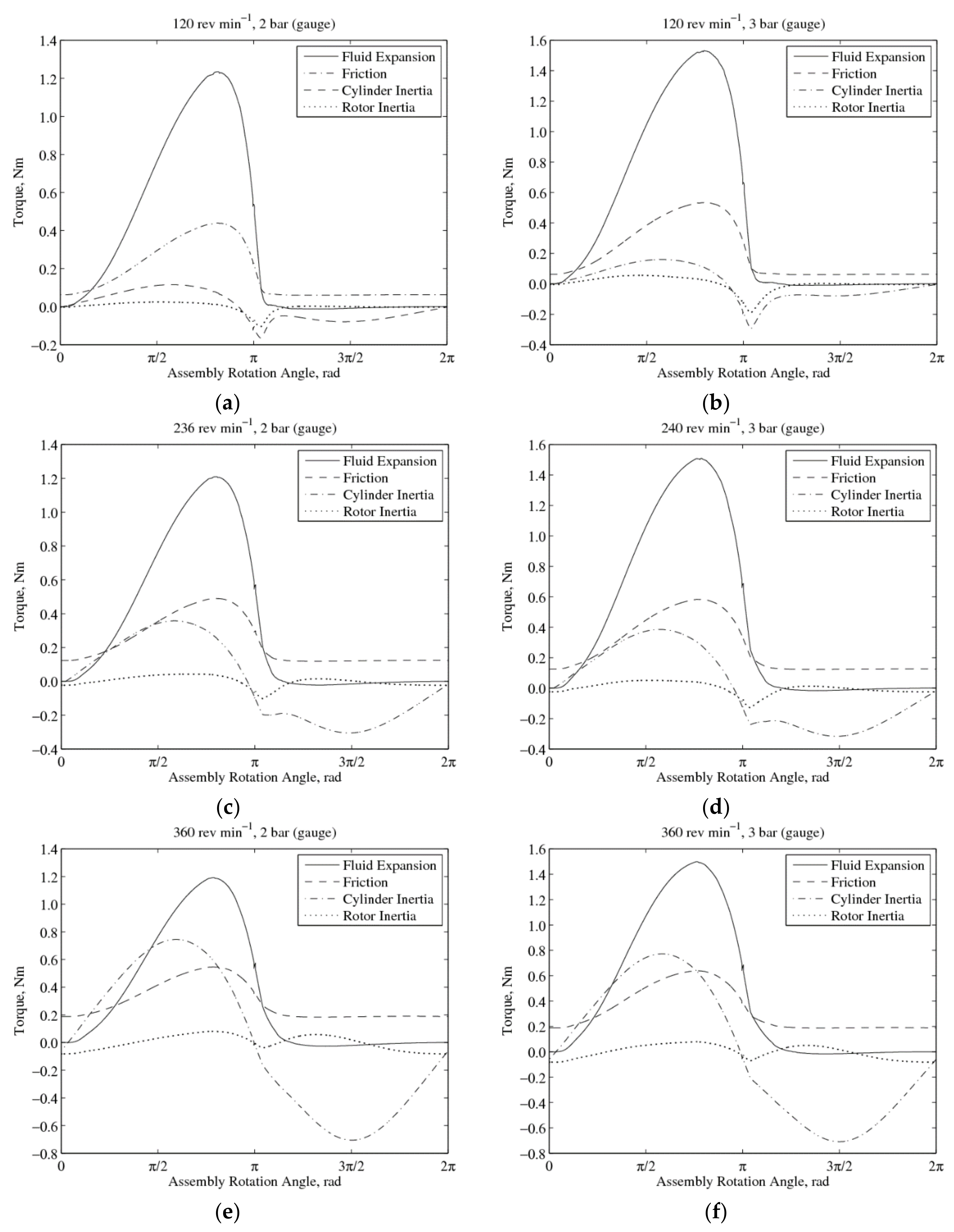
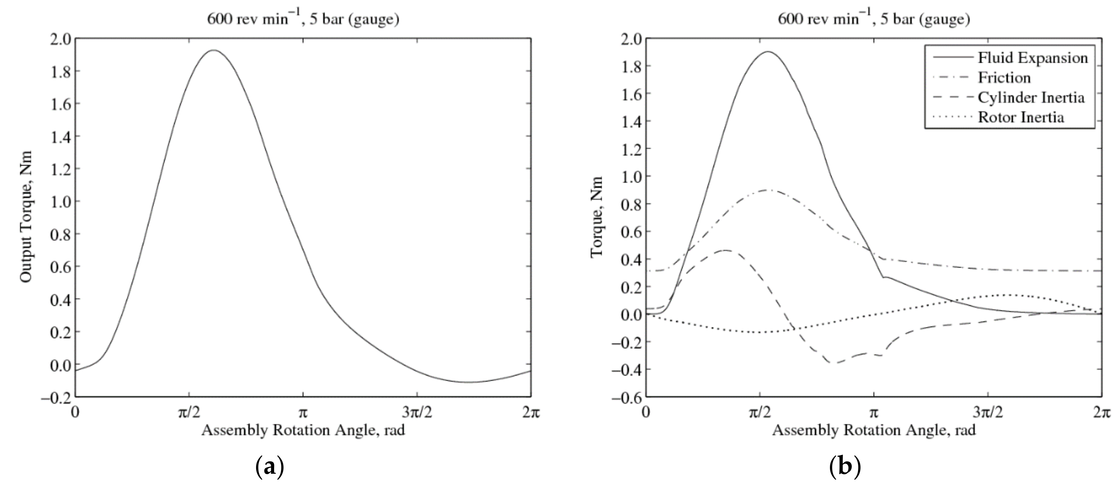
4.3. Torque Components

The comparisons between the individual torque components affecting the rotor-cylinder assembly are shown in Figure 7. These include the fluid expansion, cylinder inertia and friction components. The gas expansion torques are characteristic of the operating pressure and the inertia torques are characteristic of the operating speed.
At a low operating speed, the amplitude of the inertia torque is small and the output torque is dominated by the fluid expansion component. However, as the speed increases, the inertia component becomes more significant and is comparable to the fluid expansion component.
In addition, the expansion torque of the RV expander is not constant and is positive in the first half of the cycle (0 to π rad) and drops below zero in the second half (π to 2π rad). This is due to its operating principle, as work is extracted from the gas expansion in the first half and subsequently, work is expended to discharge the gas from the working chamber. In spite of this, the overall average output torque is still largely positive.
To this end, the negative cylinder inertia for the second half of the cycle shown in Figure 7 shows that the cylinder inertia in the RV expander might be beneficial and makes up the bulk of the output torque in the second half of the cycle. At a higher operating speed of 360 rev min−1 in Figure 6e,f, the output torque from the expander continued to stay positive in the second half of the cycle, with the drawback of requiring a larger torque to drive the entire mechanism during the starting cycle.
Hence, for high operating speeds, the inlet pressure has to be higher so that the fluid expansion torque would be sufficient to overcome the increased cylinder inertia at higher rotation speeds.

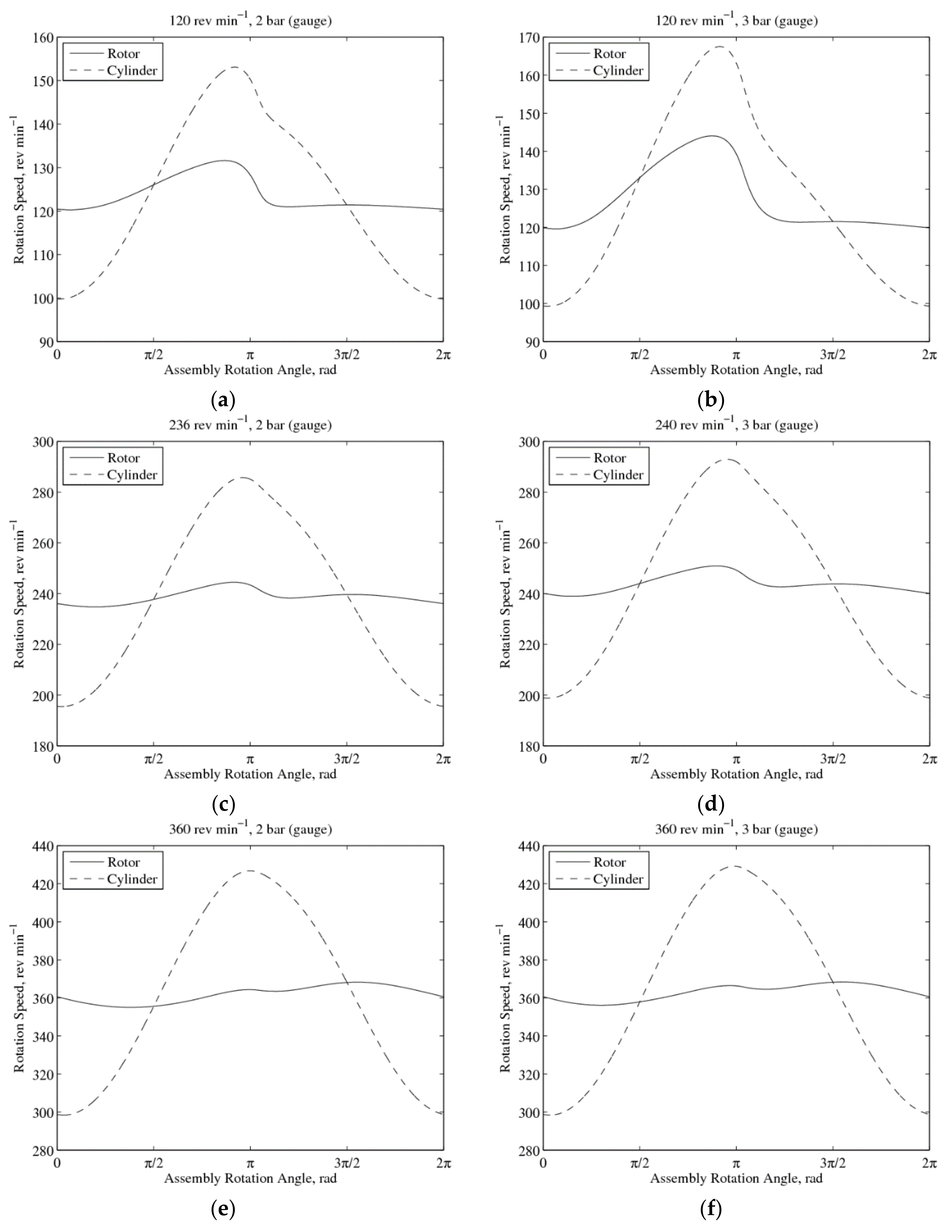
4.4. Secondary Vibration Mode

The presence of a secondary waveform in the measurements indicate that the vibration of the RV prototype is bimodal; arising from the presence of a clearance gap between the vane and the vane slot due to manufacturing tolerances. This phenomenon is termed as ‘vane knocking’ [42]. The eccentricity between the rotor and cylinder centres of rotation causes their rotation speeds to vary during operation. Figure 8 shows the theoretical variation in rotation speeds between the rotor and cylinder due to their eccentricity with no clearance gap. As eccentricity increases, the variation between the rotation speeds increases as well.
Due to the clearance gap and differences in rotation speeds, there will be instances when the vane will lose contact momentarily with the vane slot wall on the cylinder resulting in the oscillation of the vane slot wall about the vane. Figure 9 shows the oscillation of the entire assembly during prototype operation.
As the driven cylinder component has a larger moment of inertia compared to the rotor, the resulting impacts would distort the output torque of the expander as observed in the measurements. In Figure 6a,e,f, the impacts coincide with the peak torque which caused the large discrepancies between the measured and calculated value. In Figure 6f, these impacts have caused the peak torque to be higher than calculated in addition to a phase shift.
It is also noted that the secondary vibration tends to be less significant at higher rotation speeds and this is due to the reduction in oscillation times at high speeds; the time period in which the vane loses contact with the slot wall gets shorter at higher speeds and consequently, the change in angular momentum of the cylinder is less pronounced upon impact. Hence, the model was noted to be more accurate at higher operating speeds evident in Table 3, with the exception of Figure 6e, in which the peak torque was distorted by the impact.
In addition, the approximation in modelling the motor torque curve as a six-order polynomial function would have contributed to some of the discrepancies as well. Apart from the large errors observed for some of the operating conditions, the model was still able to calculate the output torque for the other operating conditions with ±10% accuracy.

5. Operating and Design Analysis

With the theoretical model validated, it shall be used to investigate the factors affecting torque output to improve expander performance.

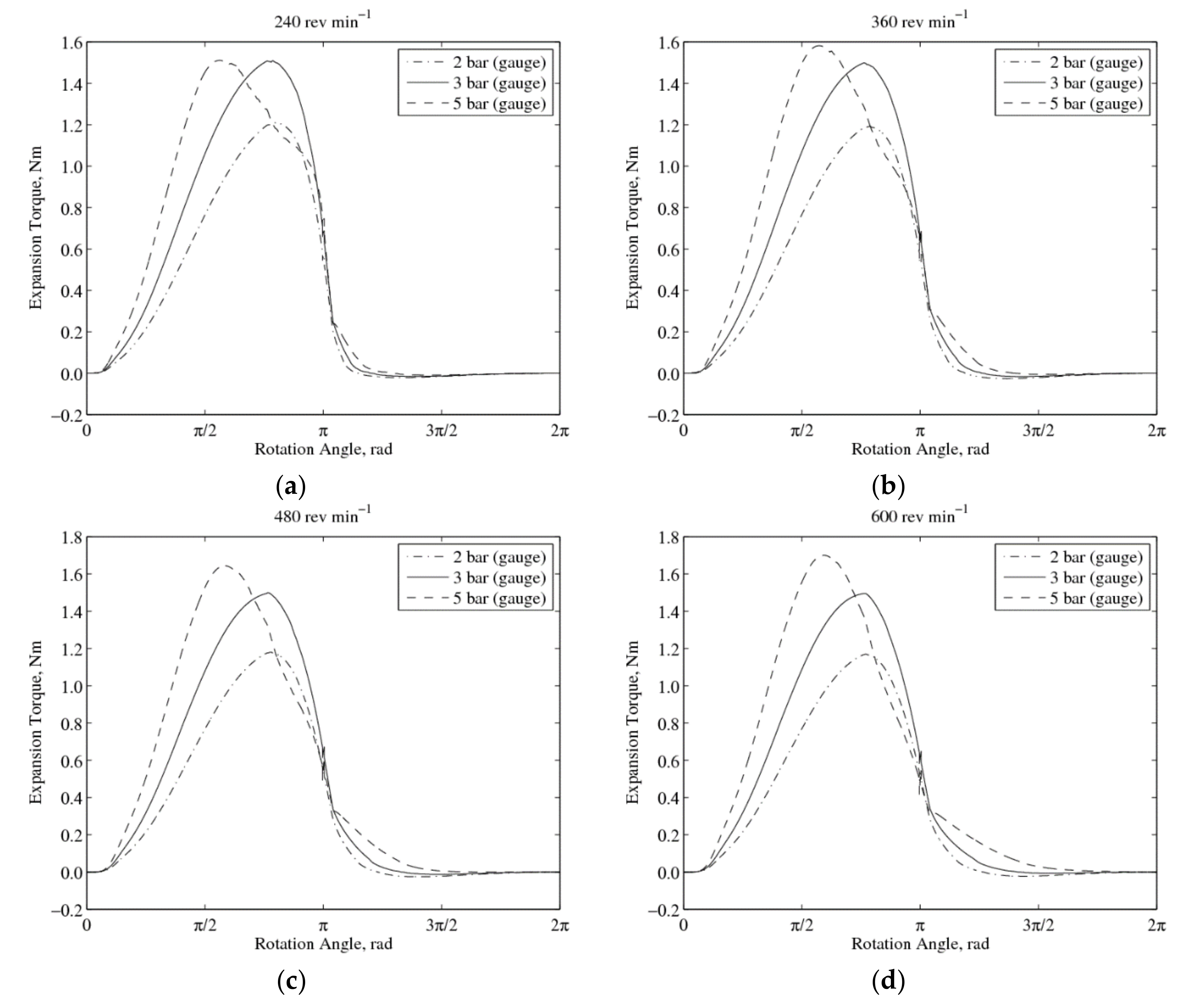
5.1. Effect of Inlet Pressures and Operating Speeds

It is evident that higher operating speeds would result in higher rotational inertias of the assembly and this would require a high inlet pressure so as to provide sufficient expansion torque to overcome the inertia. Figure 10 shows the variation of the gas expansion torque at various rotation speeds. At low operating speeds, increasing the inlet pressure in an attempt to increase the output torque would result in diminishing returns. This is due to the consequence of increased leakage at higher inlet pressures when operating speeds are low.
Generally, better volumetric efficiency is achieved when high inlet pressures are paired with high operating speeds as leakage would be less severe. For the effect on expander performance for inlet pressures between 2 and 30 bars with operating speeds between 600 and 1800 rev min−1, reference is made to the study by Subiantoro and Ooi [43].

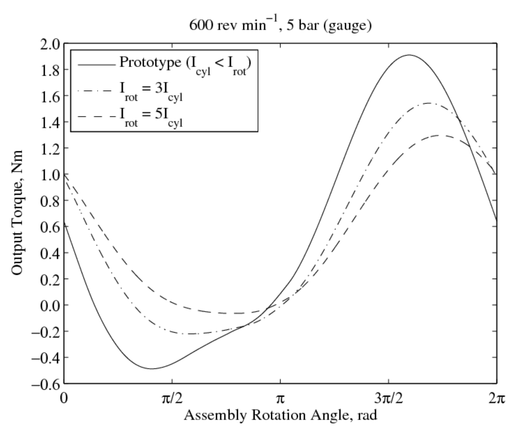
5.2. Effect of Rotor Inertia

In the RV expander prototype, the shaft work from the rotor is extracted. However, since the rotor is lighter than the cylinder, the torque required for the cylinder inertia is higher than that of the rotor and this effect is pronounced at higher rotation speeds, evident in Figure 7. Therefore, it would be beneficial to have a heavier rotor to maintain angular momentum in the first half of the cycle. This can be accomplished by adding a flywheel to the rotor shaft. Figure 11 shows the effects of having a heavier rotor in the RV prototype for a steady-state operating speed of 600 rev min−1 and inlet pressure of 5 bar (gauge). Note, an increase in rotor inertia would lower the peak output torque, but at the same time improve the negative dip in output torque during the first cycle. Therefore, adding a flywheel to increase the rotor inertia provides a more reliable output torque.

5.3. Alternate Mechanism Design

Alternatively, the bearing configuration of the RV mechanism can be redesigned such that the shaft work is extracted from the cylinder instead. This would be classified as that of a type-II RV mechanism [44] and its performance was found to be better [43] than that of the type-I mechanism used in the experiment. Figure 12 shows the performance of a type-II RV expander operating at 600 rev min−1 with an inlet pressure of 5 bar (gauge). Compared to the output torque characteristic in Figure 11, the peak output torque value remains largely unchanged but occurs in the first half cycle instead with a minor dip for the negative torque output in the second half cycle.
From the theoretical analysis, as shaft work is now extracted from the cylinder, the inertia of the cylinder at the starting cycle is now used to overcome the assembly friction, resulting in a peak torque comparable to that of the gas expansion torque. Compared to the type-I RV expander prototype in which the peak output torque arises from the rotational inertia of the cylinder, a redesigned type-II RV expander would produce a more consistent torque.

6. Conclusions

The fluctuations in RV air expander output torque are better modelled by considering the rotational vibration of the assembly during steady state operation, and a Lagrangian approach has been proposed for modelling the multi-component assembly. The theoretical model is able to calculate the characteristic of the output torque albeit with discrepancies for the value and phase angle of the peak torque. These discrepancies are mainly attributed to the vane knocking effect arising from manufacturing tolerences, which were ignored as a necessary assumption in developing the model.
The conclusions are summarised as follows:
  • The vibration of the RV air expander prototype is bimodal.
  • The rotor and cylinder rotate at different speeds due to eccentricity and the presence of a clearance gap between the vane and vane slot wall cause oscillations of the cylinder about the rotor, termed as ‘vane knocking’.
  • The resulting impacts between the vane and vane slot wall affect the output torque of the expander especially since the cylinder possesses higher rotational inertia.
  • These impacts can affect the magnitude of the peak output torque if the instances of impacts coincide with the maximum torque output.
  • However, this phenomenon is less significant at high operating speeds since the oscillation time is reduced.
  • For the type-I RV mechanism, since cylinder inertia increases with operating speed, high inlet pressures are required at high rotation speeds to improve performance.
  • Although, high cylinder inertia causes a negative output in the first half of the cycle, the momentum of the cylinder contributes to the peak output torque in the second half of the cycle.
  • Adding a flywheel to the type-I RV mechanism to increase the rotor inertia would improve the quality of the output torque but with lower peak torque values.
  • When the shaft work is extracted from the cylinder instead (type-II RV mechanism), better performance is achieved as the larger cylinder inertia is now used to overcome frictional losses.

Author Contributions

Conceptualization, A.S. and K.T.O.; methodology, K.T.A.; validation, K.T.A.; analysis, K.T.A.; prototype design, A.S. and K.T.O.; experiment investigation, A.S.; data curation, A.S.; writing—original draft preparation, K.T.A.; writing—review and editing, K.T.A., A.S. and K.T.O.; supervision, K.T.O.; project administration, K.T.O. All authors have read and agreed to the published version of the manuscript.

Funding

This work was financially supported in part by the Singapore National Research Foundation under its Campus for Research Excellence and Technological Enterprise (CREATE) programme.

Conflicts of Interest

The authors declare no conflict of interest.

References

  1. Huang, K.D.; Tzeng, S.-C. Development of a hybrid pneumatic-power vehicle. Appl. Energy 2005, 80, 47–59. [Google Scholar] [CrossRef]
  2. Dimitrova, Z.; Maréchal, F. Gasoline hybrid pneumatic engine for efficient vehicle powertrain hybridization. Appl. Energy 2015, 151, 168–177. [Google Scholar] [CrossRef]
  3. Wang, L.; Li, D.F.; Xu, H.X.; Fan, Z.P.; Dou, W.B.; Yu, X.L. Research on a pneumatic hybrid engine with regenerative braking and compressed-air-assisted cranking. Proc. Inst. Mech. Eng. Part D J. Automob. Eng. 2016, 230, 406–422. [Google Scholar] [CrossRef]
  4. Huang, K.D.; Tzeng, S.-C.; Chang, W.-C. Energy-saving hybrid vehicle using a pneumatic-power system. Appl. Energy 2005, 81, 1–18. [Google Scholar] [CrossRef]
  5. Fang, Y.; Lu, Y.; Yu, X.; Roskilly, A.P. Experimental study of a pneumatic engine with heat supply to improve the overall performance. Appl. Therm. Eng. 2018, 134, 78–85. [Google Scholar] [CrossRef] [Green Version]
  6. Hung, Y.-H.; Tung, Y.-M.; Li, H.-W. A real-time model of an automotive air propulsion system. Appl. Energy 2014, 129, 287–298. [Google Scholar] [CrossRef]
  7. Wang, Y.-W.; You, J.-J.; Sung, C.-K.; Huang, C.-Y. The applications of piston type compressed air engines on motor vehicles. Procedia Eng. 2014, 79, 61–65. [Google Scholar] [CrossRef] [Green Version]
  8. Shen, Y.-T.; Hwang, Y.-R. Design and implementation of an air-powered motorcycles. Appl. Energy 2009, 86, 1105–1110. [Google Scholar] [CrossRef]
  9. Zhang, Y.; Nishi, A. Low-pressure air motor for wall-climbing robot actuation. Mechatronics 2003, 13, 377–392. [Google Scholar] [CrossRef]
  10. Lu, C.-H.; Hwang, Y.-R.; Shen, Y.-T. Backstepping sliding mode tracking control of a vane-type air motor X-Y table motion system. Isa Trans. 2011, 50, 278–286. [Google Scholar] [CrossRef]
  11. Fukuta, M.; Anzai, F.; Motozawa, M.; Terawaki, H.; Yanagisawa, T. Performance of radial piston type reciprocating expander for CO2 refrigeration cycle. Int. J. Refrig. 2014, 42, 48–56. [Google Scholar] [CrossRef]
  12. Baek, J.S.; Groll, E.A.; Lawless, P.B. Piston-cylinder work producing expansion device in a transcritical carbon dioxide cycle. Part I: Experimental investigation. Int. J. Refrig. 2005, 28, 141–151. [Google Scholar] [CrossRef]
  13. Baek, J.S.; Groll, E.A.; Lawless, P.B. Piston-cylinder work producing expansion device in a transcritical carbon dioxide cycle. Part II: Theoretical model. Int. J. Refrig. 2005, 28, 152–164. [Google Scholar] [CrossRef]
  14. Zhang, B.; Peng, X.; He, Z.; Xing, Z.; Shu, P. Development of a double acting free piston expander for power recovery in transcritical CO2 cycle. Appl. Therm. Eng. 2007, 27, 1629–1636. [Google Scholar] [CrossRef]
  15. Kovačević, A.; Stošić, N.; Smith, I.K. Numerical simulation of combined screw compressor–expander machines for use in high pressure refrigeration systems. Simul. Model. Pract. Theory 2006, 14, 1143–1154. [Google Scholar] [CrossRef] [Green Version]
  16. Wang, W.; Wu, Y.; Ma, C.; Liu, L.; Yu, J. Preliminary experimental study of single screw expander prototype. Appl. Therm. Eng. 2011, 31, 3684–3688. [Google Scholar] [CrossRef]
  17. Wang, W.; Wu, Y.; Ma, C.; Xia, G.; Wang, J. Experimental study on the performance of single screw expanders by gap adjustment. Energy 2013, 62, 379–384. [Google Scholar] [CrossRef]
  18. Kovacevic, A.; Rane, S. 3D CFD Analysis of a Twin Screw Expander. In 8th International Conference on Compressors and Their Systems; Elsevier: Amsterdam, The Netherlands, 2013; pp. 417–429. [Google Scholar] [CrossRef]
  19. Yang, B.; Peng, X.; He, Z.; Guo, B.; Xing, Z. Experimental investigation on the internal working process of a CO2 rotary vane expander. Appl. Therm. Eng. 2009, 29, 2289–2296. [Google Scholar] [CrossRef]
  20. Xia, C.; Zhang, W.; Bu, G.; Wang, Z.; Shu, P. Experimental study on a sliding vane expander in the HFC410A refrigeration system for energy recovery. Appl. Therm. Eng. 2013, 59, 559–567. [Google Scholar] [CrossRef]
  21. Naranjo, J.; Kussul, E.; Ascanio, G. A new pneumatic vanes motor. Mechatronics 2010, 20, 424–427. [Google Scholar] [CrossRef]
  22. Guangbin, L.; Yuanyang, Z.; Liansheng, L.; Pengcheng, S. Simulation and experiment research on wide ranging working process of scroll expander driven by compressed air. Appl. Therm. Eng. 2010, 30, 2073–2079. [Google Scholar] [CrossRef]
  23. Mendoza, L.C.; Navarro-Esbrí, J.; Bruno, J.C.; Lemort, V.; Coronas, A. Characterization and modeling of a scroll expander with air and ammonia as working fluid. Appl. Therm. Eng. 2014, 70, 630–640. [Google Scholar] [CrossRef]
  24. Haiqing, G.; Yitai, M.; Minxia, L. Some design features of CO2 swing piston expander. Appl. Therm. Eng. 2006, 26, 237–243. [Google Scholar] [CrossRef]
  25. Zhao, L.; Li, M.; Ma, Y.; Liu, Z.; Zhang, Z. Simulation analysis of a two-rolling piston expander replacing a throttling valve in a refrigeration and heat pump system. Appl. Therm. Eng. 2014, 66, 383–394. [Google Scholar] [CrossRef]
  26. Li, M.; Ma, Y.; Tian, H. A rolling piston-type two-phase expander in the transcritical CO2 Cycle. Hvacr Res. 2009, 15, 729–741. [Google Scholar] [CrossRef]
  27. Yap, K.S.; Ooi, K.T.; Chakraborty, A. Analysis of the novel cross vane expander-compressor: Mathematical modelling and experimental study. Energy 2018, 145, 626–637. [Google Scholar] [CrossRef]
  28. Teh, Y.L.; Ooi, K.T.; Djamari, D.W. Theoretical study of a novel refrigeration compressor—Part II: Performance of a rotating discharge valve in the revolving vane (RV) compressor. Int. J. Refrig. 2009, 32, 1103–1111. [Google Scholar] [CrossRef]
  29. Teh, Y.L.; Ooi, K.T. Theoretical study of a novel refrigeration compressor- Part III: Leakage loss of the revolving vane (RV) compressor and a comparison with that of the rolling piston type. Int. J. Refrig. 2009, 32, 945–952. [Google Scholar] [CrossRef]
  30. Subiantoro, A.; Ooi, K.T. Introduction of the revolving vane expander. Hvac R Res. 2009, 15, 801–816. [Google Scholar] [CrossRef]
  31. Subiantoro, A.; Ooi, K.T. Analysis of the revolving vane (RV-0) expander, Part 1: Experimental investigations. Int. J. Refrig. 2012, 35, 1734–1743. [Google Scholar] [CrossRef]
  32. Subiantoro, A.; Ooi, K.T. Analysis of the Revolving Vane (RV-0) expander, part 2: Verifications of theoretical models. Int. J. Refrig. 2012, 35, 1744–1756. [Google Scholar] [CrossRef]
  33. Subiantoro, A.; Yap, K.S.; Ooi, K.T. Experimental investigations of the revolving vane (RV-I) expander. Appl. Therm. Eng. 2013, 50, 393–400. [Google Scholar] [CrossRef]
  34. Naseri, A.; Norris, S.; Subiantoro, A. Experimental investigation of a prototype semi-dry revolving vane expander: Design challenges and performance criteria. Energy 2020, 205, 118063. [Google Scholar] [CrossRef]
  35. Aw, K.T.; Ooi, K.T. Theoretical Analysis of Revolving Vane Compressor Vibrations. In Proceedings of the International Compressor Engineering Conference, West Lafayette, IN, USA, 14–17 July 2014. [Google Scholar]
  36. Tan, K.M.; Ooi, K.T. A novel revolving vane compressor with a fixed-vane. Int. J. Refrig. 2011, 34, 1980–1988. [Google Scholar] [CrossRef]
  37. Yanagisawa, T.; Shimizu, T. Leakage losses with a rolling piston type rotary compressor. I. Radial clearance on the rolling piston. Int. J. Refrig. 1985, 8, 75–84. [Google Scholar] [CrossRef]
  38. Liu, R.; Zhou, Z. Heat Transfer Between Gas and Cylinder Wall of Refrigerating Reciprocating Compressor. In Proceedings of the International Compressor Engineering Conference, West Lafayette, IN, USA, 11–13 July 1984; pp. 110–115. [Google Scholar]
  39. Tan, K.M.; Ooi, K.T. Heat transfer in compression chamber of a revolving vane (RV) compressor. Appl. Therm. Eng. 2011, 31, 1519–1526. [Google Scholar] [CrossRef]
  40. Yanagisawa, T.; Mori, M.; Shimizu, T.; Ogi, Y. Vibration of a rolling piston type rotary compressor. Int. J. Refrig. 1984, 7, 237–244. [Google Scholar] [CrossRef]
  41. Thornton, S.T.; Marion, J.B. Classical Dynamics of Particles and Systems, 5th ed.; Brooks/Cole: Belmont, CA, USA, 2004. [Google Scholar]
  42. Subiantoro, A. Development of a Revolving Vane Expander; Nanyang Technological University: Singapore, 2012. [Google Scholar]
  43. Subiantoro, A.; Ooi, K.T. Comparison and performance analysis of the novel revolving vane expander design variants in low and medium pressure applications. Energy 2014, 78, 747–757. [Google Scholar] [CrossRef]
  44. Tan, K.M.; Ooi, K.T. Journal bearings design for a novel revolving vane compressor. Int. J. Refrig. 2011, 34, 94–104. [Google Scholar] [CrossRef]
Figure 1. Revolving vane schematic.
Machines 08 00058 g001
Figure 2. Type-I RV geometric relations; (a) Type-I RV layout; (b) Type-I RV geometry.
Machines 08 00058 g002
Figure 3. Expander experiment schematic [33].
Machines 08 00058 g003
Figure 4. Expander experiment setup [33].
Machines 08 00058 g004
Figure 5. Motor load curve.
Machines 08 00058 g005
Figure 6. Calculated and measured output torques: (a) 120 rev min−1 with 2 bar (gauge) inlet pressure; (b) 120 rev min−1 with 3 bar (gauge) inlet pressure; (c) 236 rev min−1 with 2 bar (gauge) inlet pressure; (d) 240 rev min−1 with 3 bar (gauge) inlet pressure; (e) 360 rev min−1 with 2 bar (gauge) inlet pressure; (f) 360 rev min−1 with 3 bar (gauge) inlet pressure.
Machines 08 00058 g006
Figure 7. Torque components: (a) 120 rev min−1 with 2 bar (gauge) inlet pressure; (b) 120 rev min−1 with 3 bar (gauge) inlet pressure; (c) 236 rev min−1 with 2 bar (gauge) inlet pressure; (d) 240 rev min−1 with 3 bar (gauge) inlet pressure; (e) 360 rev min−1 with 2 bar (gauge) inlet pressure; (f) 360 rev min−1 with 3 bar (gauge) inlet pressure.
Machines 08 00058 g007
Figure 8. Variation in rotation speeds: (a) 120 rev min−1 with 2 bar (gauge) inlet pressure; (b) 120 rev min−1 with 3 bar (gauge) inlet pressure; (c) 236 rev min−1 with 2 bar (gauge) inlet pressure; (d) 240 rev min−1 with 3 bar (gauge) inlet pressure; (e) 360 rev min−1 with 2 bar (gauge) inlet pressure; (f) 360 rev min−1 with 3 bar (gauge) inlet pressure.
Machines 08 00058 g008
Figure 9. Secondary vibration mode.
Machines 08 00058 g009
Figure 10. Variation of expansion torques at different speeds: (a) 240 rev min−1; (b) 360 rev min−1; (c) 480 rev min−1; (d) 600 rev min−1.
Machines 08 00058 g010
Figure 11. Effect of rotor inertia on output torque.
Machines 08 00058 g011
Figure 12. Type-II revolving vane expander performance: (a) Output torque; (b) Torque components.
Machines 08 00058 g012
Table 1. Power Loss Coefficients.
CoefficientValue
ξ3.0 × 10⁻¹
ζ5.0 × 10⁻³
Table 2. RV Expander Prototype Dimensions.
ComponentDimension
Rotor radius (Rr), mm29.0
Cylinder inner radius (Rc), mm35.0
Chamber length (le), mm25.0
Vane length, mm16.0
Vane width, mm4.0
Working volume, cm312.0
Table 3. Peak Torque Comparisons.
Average Operating Speed, rev min−1Inlet Pressure, Bar (Gauge)Measure Peak Torque, NmCalculated Peak Torque, NmError, %
12020.5400.731–35.4
12030.8730.928–6.3
23620.5330.5065.1
24030.7180.6785.6
36020.4010.490–22.2
36030.5430.4988.3

