Abstract
In this paper, one model of flexible space-vector-based hybrid pulse width modulation (HPWM) transition algorithm consisting of selective harmonic elimination pulse width modulation (SHEPWM) and selective harmonic mitigation pulse width modulation (SHMPWM) is applied and examined in a 10kV grid with a three-level neutral point clamped (3L-NPC) grid-connected inverter. These two modulation techniques are used to produce the appropriate firing pulses for 3L-NPC grid-connected inverters in different cases. SHMPWM is adopted to the grid-connected inverters to mitigate the required odd non-triplen harmonics according to the requirements of grid codes EN 50160 and CIGRE WG 36-05, while the firing pulses generated using SHEPWM is used to eliminate the primary low-order odd non-triplen harmonics completely. Meanwhile, one smooth and fast transition scheme is proposed by providing a suitable switching angles set at the transition point. Finally, it is demonstrated and validated by the MATLAB/SIMULINK model that smooth and quick transition is realized and there is no sudden change of current during the transition, as expected. Furthermore, this hybrid PWM technique is universal for different PWM methods based on the specific operating conditions.
1. Introduction
Over the last few decades, increasing environmental concerns and government initiatives to reduce carbon emissions have surged the demand for interlinking multilevel inverters (MLI) and renewable energy sources (RES), and the market for MLI and RES is expected to grow at its highest speed. Hence, it is desirable to use renewable and sustainable energy technologies, such as high-voltage direct current (HVDC) systems, flexible alternate current transmission systems (FACTS), and electric vehicles and hybrid electric vehicles (EVs/HEVs), solar photovoltaic system, wind turbine, tidal power generation, electric vehicles system, and hybrid microgrid [1,2,3,4,5], as shown in Figure 1. MLIs play an important role in integrating the DC and AC power networks and energy consumption [6,7] and have been designed by utilizing the combination of a large number of semiconductor power switches that have the ability to withstand higher voltage ratings compared to the conventional two-level full-bridge converters and also have several inherent characteristics, such as low switching frequency, small electromagnetic interference (EMI), lower dv/dt stress at the output terminals and reduced total harmonics distortion (THD). There are several topologies available for these kinds of industrial and civil applications: flying capacitor (FC), cascaded H-bridge (CHB), and neutral-point-clamped (NPC), among which the 3L-NPC inverters is one of the most successful and widely applied topologies in medium and high-power regenerative applications. For 3L-NPC inverters, pulse width modulation (PWM) is one of the critical techniques, and so far, it mainly includes carrier-based sinusoidal PWM (CB-SPWM), space vector PWM (SVPWM), selective harmonic elimination PWM (SHEPWM), and selective harmonic mitigation PWM (SHMPWM). In consideration of the distribution of each harmonic, total harmonic distortion (THD) and system losses, these diverse PWM techniques have their own various performances. However, low switching frequency requires special attention in high-power applications, which is responsible for decreasing switching loss as well as enhancing system efficiency [8,9,10,11,12]. Therefore, among these techniques, SHEPWM and SHMPWM are more suitable for such kind an application.
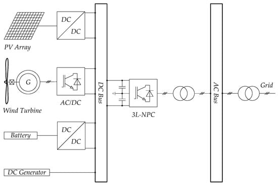
Figure 1.
Configuration of distributed grid system based on 3L-NPC inverters.
In order to further combine the advantages of different PWM methods, hybrid PWM (HPWM) was proposed [13,14,15,16,17,18,19,20,21,22,23]. The biggest difficulty of this scheme is how to achieve the fast and smooth transition since the transition between various PWM methods may cause currents to fluctuate. In Reference [13], one HPWM method, which combines the merits of SVPWM and SHEPWM, is presented, and the smooth and quick transition is realized by optimizing the switching state during transition. In References [19] and [20], one HPWM method, which combines different SHEPWMs, is proposed and is applied to provide variable frequency of output voltage based on different switching patterns. Finally, in References [21] and [22], another HPWM technique, called space-vector-based HPWM, is used to reduce current ripple and peak-to-peak torque ripple in induction motor drives, respectively. However, all the above examples do not explain the logic of the transition scheme in great detail.
Therefore, in view of the difficulty of HPWMs and the concept of space-vector-based HPWM, one flexible space-vector-based HPWM transition algorithm for 3L-NPC grid-connected inverters is proposed in this paper, which fully takes advantage of the merits of both SHEPWM and SHMPWM. SHMPWM is adopted to the grid-connected inverters to mitigate the required odd non-triplen harmonics according to the requirements of grid codes EN 50160 and CIGRE WG 36-05, while the firing pulses generated using SHEPWM is used to eliminate the primary low-order odd non-triplen harmonics completely. Here, 15 switching angles are determined to be used, which means that the switching frequency is 750 Hz. Meanwhile, one smooth and quick transition scheme is proposed by providing suitable switching angles set at the transition point; the concept is relatively simple to implement but works well. Finally, it is demonstrated and validated by MATLAB/SIMULINK model that the smooth and quick transition is realized and there is no sudden change of current during the transition, as expected.
The rest of the paper is organized as follows. The formulation of SHEPWM and SHMPWM for 3L-NPC Inverters is presented in Section 2. Section 3 introduces the principle of proposed flexible space-vector-based HPWM transition algorithm between SHEPWM and SHMPWM. The simulation results obtained from a MATLAB/SIMULINK model are presented and analyzed in Section 4. Finally, the conclusion is summarized in Section 5.
2. Formulation of SHEPWM and SHMPWM for 3L-NPC Inverters
For 3L-NPC inverters, due to the quarter-symmetry of the output phase voltage waveform, only odd sine components bn are remained. That is,
where the set of N switching angles within the range [0, π/2] are arranged in ascending order, that is, , as shown in Figure 2.
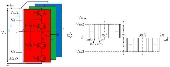
Figure 2.
Standard structure of 3L-NPC inverters and its classic output phase voltage waveform. Here, N = odd.
Furthermore, only nontriple-order harmonics were considered as 3L-NPC inverters and were primarily utilized in three-phase power systems, which meant that the triple-order harmonics could be removed automatically by itself.
2.1. Basis of SHEPWM
The main idea of SHEPWM was to make zero certain particular odd harmonics while maintaining the fundamental harmonic content, which was first introduced in 1973. The following N-equation set should be satisfied in order to obtain the effective values, which was used to eliminate N-1 odd harmonics (the harmonic value Hn), as provided by Equation (2). After calculation, several switching patterns of SHEPWM were obtained, the first harmonic value was equal to the desired modulation index Ma (here, ) and the undesired odd harmonics were set to zero.
where n is the maximum number of odd nontriple-order harmonics, which were considered to be eliminated and .
It is worth noting that the rest of the harmonics could be very high and uncontrollable while the previous N-1 odd harmonics were set to zero. Nowadays, the required level of voltage, current and power quality must be kept under the desired limits, which means SHEPWM, with a small quantity of switching angles, is not suitable for many power systems.
While using additional grid-tied tuned filters and increasing the number of switching angles can be utilized in order to minimize or eliminate these remaining undesired high-order harmonics, the total expenses and switching losses of the power systems will be increased.
2.2. Basis of SHMPWM
The highest power quality can be obtained at low switching frequencies through the SHEPWM method, in comparison to other PWM methods. However, the disadvantage of leaving the rest of the harmonics completely uncontrolled makes energy injection has to be solved in order to keep the required voltage and current level of the specific grid.
The problems presented in SHEPWM can be solved by SHMPWM. For SHMPWM, the elimination of certain specific odd harmonics is not its main objective, but all the considered harmonics and the value of the total harmonic distortion (THD) of the output voltage are considered to be a global problem and should be limited to acceptable levels, as determined by the grid codes, such as EN 50160 requirements [24] and CIGRE WG 36-05 requirements [25], as shown in Table 1.

Table 1.
Grid codes EN 50160 and CIGRE WG 36–05.
The harmonic error level En of each harmonic should be less than the maximum value Ln of the applied grid codes, and the mathematical expression of SHMPWM is defined in Equation (3).
3. Principle of Proposed Flexible Space-Vector-Based HPWM Transition Algorithm between SHEPWM and SHMPWM
To take advantages of these two PWM methods, one control block diagram of the flexible space-vector-based HPWM transition algorithm between SHEPWM and SHMPWM for 3L-NPC inverters is presented, as shown in Figure 3. In this scheme, the target is the realization of the fast and smooth transition process without any abruptly changing currents.
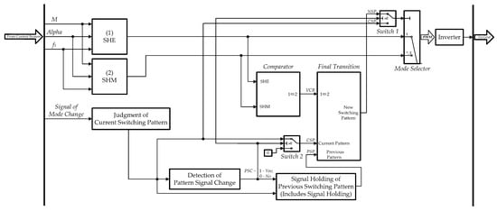
Figure 3.
Control block diagram of HPWM transition algorithm between SHEPWM and SHMPWM for 3L-NPC inverters.
To make it easier to understand, the logic-mathematic statements (4) are presented.
Figure 4 shows the flow chart of proposed HPWM transition algorithm, and its specific process steps are presented as follow:
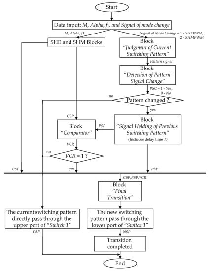
Figure 4.
Flow chart of the proposed HPWM transition algorithm.
- When the power system starts running, the SHE and SHM blocks produce their own switching patterns according to M, Alpha and f1, which are obtained from the closed-loop control system;
- First, the block “Judgment of Current Switching Pattern” starts to detect the current switching pattern based on the “Signal of Mode Change” (here, the mode is SHEPWM or SHMPWM);
- Then, the next block “Detection of Pattern Signal Change” starts to detect the change of the pattern signal in the meantime, and output “the signal of the pattern signal change, PSC” (here, 1—Yes, 0—No);
- If the pattern signal is changed, the block “Signal Holding of Previous Switching Pattern (Includes Signal Holding)” starts to hold the signal of the previous switching pattern for some time (here, delay time T is determined by the specific object);
- The block “Comparator” is used for the real-time comparison of the output space vectors (SV) of each pair of phase legs between SHEPWM and SHMPWM, as shown in Figure 5;
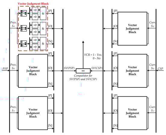 Figure 5. Intuitive details of the block “Comparator”.
 - Finally, three types of signals, namely “the signal of the previous switching pattern, PSP”, “the signal of the current switching pattern, CSP” and “the signal of the vector comparison result, VCR”, are fed to the block “Final Transition”. The block “Final Transition” outputs “the new switching pattern, NSP” through the lower port of “Switch 1” if all three conditions above are satisfied; Otherwise, the current switching pattern will directly pass through the upper port of “Switch 1”.
For the block “Comparator”, during the process of modulation, SHEPWM and SHMPWM waveforms will produce their own corresponding output space vectors of each pair of phase legs, which can be applied for real-time comparison. The relationship between the output space vectors and their corresponding gate signals is proposed in Table 2.
Table 2.
The relationship between the output space vectors and their corresponding gate signals.
4. Simulation Results and Analysis
In order to verify the transition algorithm and to evaluate the states of output voltage and current waveforms obtained from the 3L-NPC inverter and the 10kV grid, simulation model based on the proposed HPWM algorithm has been implemented in MATLAB/SIMULINK, as shown in Figure 6. The parameters used in the simulation are listed in Table 3.
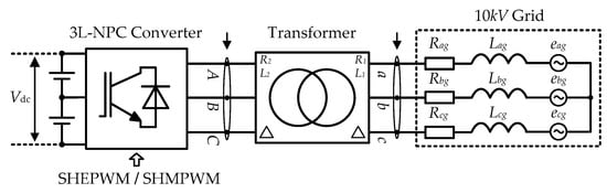
Figure 6.
Simulation model based on the proposed HPWM algorithm.
Table 3.
Parameters used in the simulation model.
Through m-file codes with the fmincon function, certain feasible solutions are calculated based on the following objective function (7). The paper only presents the result analysis when the modulation index Ma is equal to 0.8 because of limited space.
4.1. Algorithm Verification
The proposed transition algorithm can be proved by the following sequence diagram, as shown in Figure 7. The first area “A” shows the transition from SHEPWM to SHMPWM, as well as the second area “B”, presents the transition from SHMPWM to SHEPWM. Here, the time period from 0.3 s to 0.7 s was selected for demonstration. As can be seen from Figure 7, the transition process was completed when all the conditions were satisfied. After the transition, the output switching pattern remained the new state.
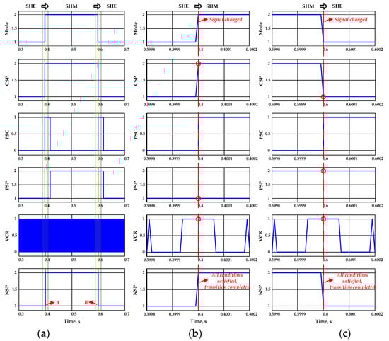
Figure 7.
Sequence diagram for proving the proposed transition algorithm: (a) Transition between SHEPWM and SHMPWM; (b) Zoom A of the transition from SHEPWM to SHMPWM; (c) Zoom B of the transition from SHMPWM to SHEPWM.
According to Figure 7b,c, the transition time is so short that it ensures the power system quickly completes the transition process. Then, the efficiency of the 3L-NPC inverter can be improved since the transition process is quick and SHEPWM and SHMPWM have lower switching frequency. The concept of proposed transition algorithm is relatively simple to implement but works well, as proved by the simulation results.
4.2. Analysis of Output Voltage and Current
Figure 8 shows the simulation results of the output voltage and current between SHEPWM and SHMPWM. It can be found from the zoom A in Figure 8b and zoom B in Figure 8c that there was no sudden change of current during the transition, as expected.
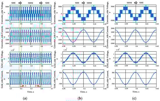
Figure 8.
Simulation results of output voltage and current between SHEPWM and SHMPWM: (a) Transition between SHEPWM and SHMPWM; (b) Zoom A of output voltage and current from SHEPWM to SHMPWM; (c) Zoom B of output voltage and current from SHMPWM to SHEPWM.
Simulation results of SHEPWM and SHMPWM at the converter side and at grid side are presented in Table 4 and Table 5, respectively. It can be seen that the simulation results of the voltage of SHMPWM all met the requirements of the grid codes EN 50160 and CIGRE WG 36-05 and were better than the simulation results of the voltage of SHEPWM. The simulation results of the current of SHEPWM were better than the simulation results of the current of SHMPWM. In this case, these two PWM methods needed to be selected according to the specific voltage and current requirements, which is also the one of the main points of this paper. Simulation results of SHEPWM and SHMPWM at the converter side.
Table 4.
Simulation results of SHEPWM and SHMPWM at the converter side.
Table 5.
Simulation results of SHEPWM and SHMPWM at grid side.
5. Conclusions
This paper proposed a flexible space-vector-based HPWM transition algorithm applied in 10 kV grid with a 3L-NPC inverter. The concept of proposed transition algorithm is relatively simple to implement but works well, as proved by the simulation results. The fast and smooth transition process is realized and there is no sudden change of current during the transition, as expected, which makes this hybrid PWM technique suitable for the grid-connected inverters. Further, the efficiency of the grid-connected inverters can be improved since the transition process is quick and SHEPWM and SHMPWM have lower switching frequencies. Furthermore, this hybrid PWM technique is universal and can be applied to other different PWM methods based on the specific operating conditions.
Author Contributions
Methodology and validation, T.J. and A.M.; writing—original draft preparation, T.J.; writing—review and editing, A.M. and A.R.; formal analysis, project administration and supervision, A.R. and V.G. All authors have read and agreed to the published version of the manuscript.
Funding
This research received no external funding.
Conflicts of Interest
The authors declare no conflict of interest.
References
- Bose, B.K. Global warming: Energy, environmental pollution and the impact of power electronics. IEEE Trans. Ind. Electron. 2010, 4, 6–17. [Google Scholar] [CrossRef]
- Kouro, S.; Malinowski, M.; Gopakumar, K.; Pou, J.; Franquelo, L.G.; Wu, B.; Rodriguez, J.; Perez, M.A.; Leon, J.I. Recent advances and industrial applications of multilevel converters. IEEE Trans. Ind. Electron. 2010, 57, 2553–2580. [Google Scholar] [CrossRef]
- Abu-Rub, H.; Holtz, J.; Rodriguez, J.; Baoming, G. Medium voltage multilevel converters—state of the art, challenges and requirements in industrial applications. IEEE Trans. Ind. Electron. 2010, 57, 2581–2596. [Google Scholar] [CrossRef]
- van Wyk, J.D.; Lee, F.C. On a future for power electronics. IEEE Trans. Emerg. Sel. Topics Power Electron. 2013, 1, 59–72. [Google Scholar] [CrossRef]
- Jing, T.; Maklakov, A.S. A review of voltage source converters for energy applications. In Proceedings of the International Ural Conference on Green Energy (UralCon), Chelyabinsk, Russia, 4–6 October 2018. [Google Scholar]
- Teodorescu, R.; Liserre, M.; RodrÕguez, P. Grid Converters for Photovoltaic and Wind Power Systems; Wiley-IEEE Press: New York, NY, USA, 2011. [Google Scholar]
- Wang, H.; Jia, H.; He, J. Parallel interlinking PWM current source converter for hybrid AC/DC microgrids. In Proceedings of the IEEE Power & Energy Society General Meeting, Chicago, IL, USA, 16–20 July 2017. [Google Scholar]
- Radionov, A.A.; Gasiyarov, V.R.; Maklakov, A.S. Hybrid PWM on the basis of SVPWM and SHEPWM for VSI as part of 3L-BtB-NPC converter. In Proceedings of the IECON—43rd Annual Conference of the IEEE Industrial Electronics Society, Beijing, China, 29 October–1 November 2017. [Google Scholar]
- Wang, H.; Liserre, M.; Blaabjerg, F. Toward reliable power electronics: Challenges, design tools, and opportunities. IEEE Ind. Electron. Mag. 2013, 7, 17–26. [Google Scholar] [CrossRef]
- Mohammed, S.A.; Abdel-Moamen, M.A.; Hasanin, B. A review of the state-of-the-art of power electronics for power system applications. JECER 2013, 1, 43–52. [Google Scholar]
- Abu-Rub, H.; Malinowski, M.; Al-Haddad, K. Power Electronics for Renewable Energy Systems, Transportation and Industrial Applications; Wiley-IEEE Press: New York, NY, USA, 2014. [Google Scholar]
- Leon, J.I.; Kouro, S.; Franquelo, L.G.; Rodriguez, J.; Wu, B. The essential role and the continuous evolution of modulation techniques for voltage-source inverters in the past, present, and future power electronics. IEEE Trans. Ind. Electron. 2016, 63, 2688–2701. [Google Scholar] [CrossRef]
- Zhang, Y.; Xu, D.; Yan, C.; Zou, S. Hybrid PWM scheme for the grid inverter. IEEE Trans. Emerg. Sel. Top. Power Electron. 2015, 3, 1151–1159. [Google Scholar] [CrossRef]
- Sharifzadeh, M.; Vahedi, H.; Sheikholeslami, A.; Labbé, P.; Al-Haddad, K. Hybrid SHM–SHE modulation technique for a four-leg NPC inverter with DC capacitor self-voltage balancing. IEEE Trans. Ind. Electron. 2015, 62, 4890–4899. [Google Scholar] [CrossRef]
- Moeini, A.; Zhao, H.; Wang, S. Improve control to output dynamic response and extend modulation index range with hybrid selective harmonic current mitigation-PWM and phase-shift PWM for four-quadrant cascaded H-bridge converters. IEEE Trans. Ind. Electron. 2017, 64, 6854–6863. [Google Scholar] [CrossRef]
- Portillo, R.; Sharifzadeh, M.; Vahedi, H.; Franquelo, L.G.; Al-Haddad, K. Improved hybrid SHM-SHE modulation technique for four-leg three-level NPC inverters. In Proceedings of the IECON—41st Annual Conference of the IEEE Industrial Electronics Society, Yokohama, Japan, 9–12 November 2015. [Google Scholar]
- Wang, Y.; Wen, X.; Guo, X.; Zhao, F.; Cong, W. The smooth transition research of different PWM modulations for vector control of induction motor in medium voltage high power. In Proceedings of the International Conference on Electrical Machines and Systems, Beijing, China, 20–23 August 2011. [Google Scholar]
- Zaragoza, J.; Pou, J.; Ceballos, S.; Robles, E.; Ibanez, P.; Villate, J.L. A comprehensive study of a hybrid modulation technique for the neutral-point-clamped converter. IEEE Trans. Ind. Electron. 2009, 56, 294–304. [Google Scholar] [CrossRef]
- Jing, T.; Maklakov, A.; Radionov, A.; Baskov, S.; Kulmukhametova, A. Research on hybrid SHEPWM based on different switching patterns. IJPEDS 2019, 10, 1875–1884. [Google Scholar]
- Jing, T.; Maklakov, A.; Radionov, A.; Gasiyarov, V. A flexible hybrid selective harmonic elimination transition algorithm to provide variable frequency of output voltage in 3L-NPC inverter. In Proceedings of the IECON—45th Annual Conference of the IEEE Industrial Electronics Society, Lisbon, Portugal, 14–17 October 2019. [Google Scholar]
- Narayanan, G.; Zhao, D.; Krishnamurthy, H.K.; Ayyanar, R.; Ranganathan, V.T. Space vector based hybrid PWM techniques for reduced current ripple. IEEE Trans. Ind. Electron. 2008, 55, 1614–1627. [Google Scholar] [CrossRef]
- Hari, V.P.K.; Narayanan, G. Space-vector-based hybrid PWM technique to reduce peak-to-peak torque ripple in induction motor drives. IEEE Trans. Ind. Appl. 2016, 52, 1489–1499. [Google Scholar]
- Jing, T.; Maklakov, A.; Radionov, A. Two selective harmonic control techniques applied in 10 kV grid with three-level NPC inverter. In Proceedings of the IEEE Russian Workshop on Power Engineering and Automation of Metallurgy Industry: Research & Practice (PEAMI), Magnitogorsk, Russia, 14–17 October 2019. [Google Scholar]
- CENELEC. Voltage Characteristics of Electricity Supplied by Public Distribution Systems, EN 50160; CENELEC: Brussels, Belgium, 2001. [Google Scholar]
- CIGRE. Harmonics, Characteristic Parameters, Methods of Study, Estimates of Existing Values in the Network, Electra No. 77; CIGRE WG 36–05; CIGRE: Paris, France, 1981. [Google Scholar]


© 2020 by the authors. Licensee MDPI, Basel, Switzerland. This article is an open access article distributed under the terms and conditions of the Creative Commons Attribution (CC BY) license (http://creativecommons.org/licenses/by/4.0/).