Weight-Vibration Pareto Optimization of a Triple Mass Flywheel for Heavy-Duty Truck Powertrains


Abstract

1. Introduction
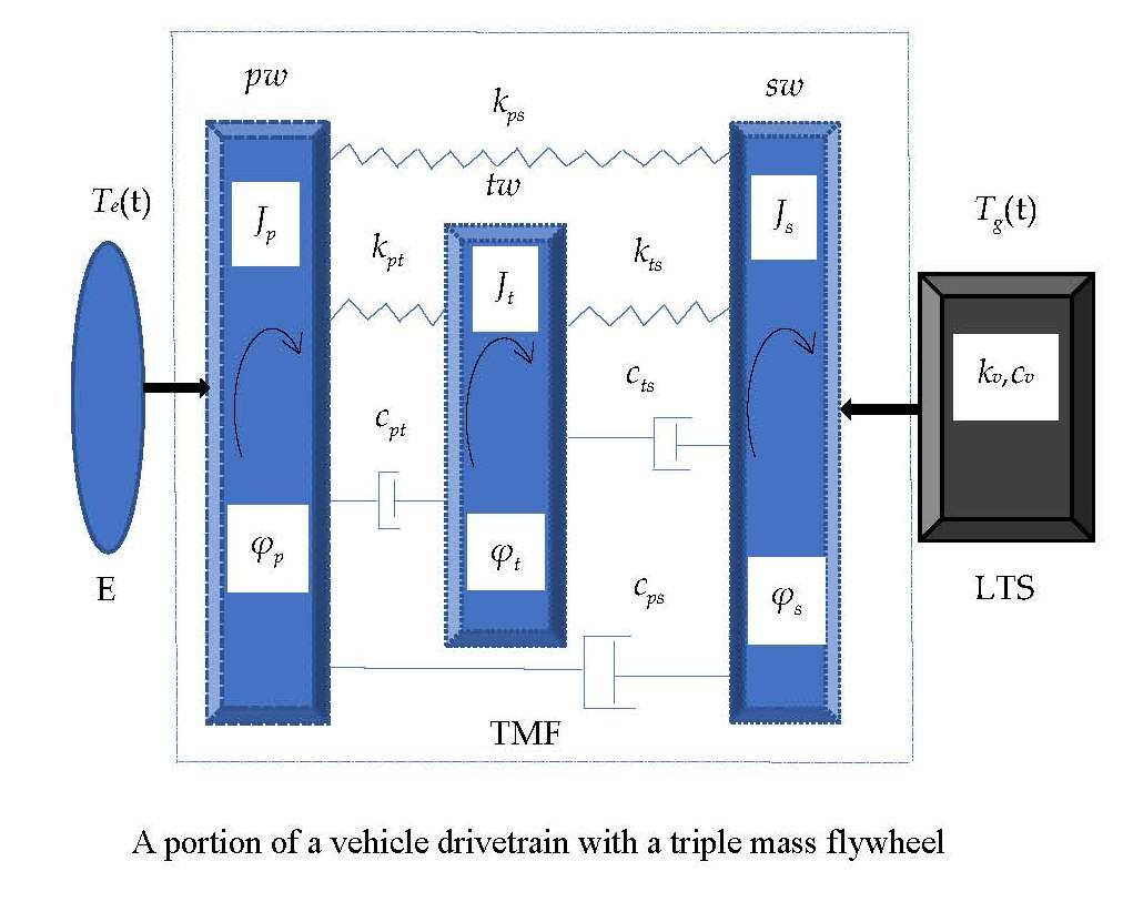
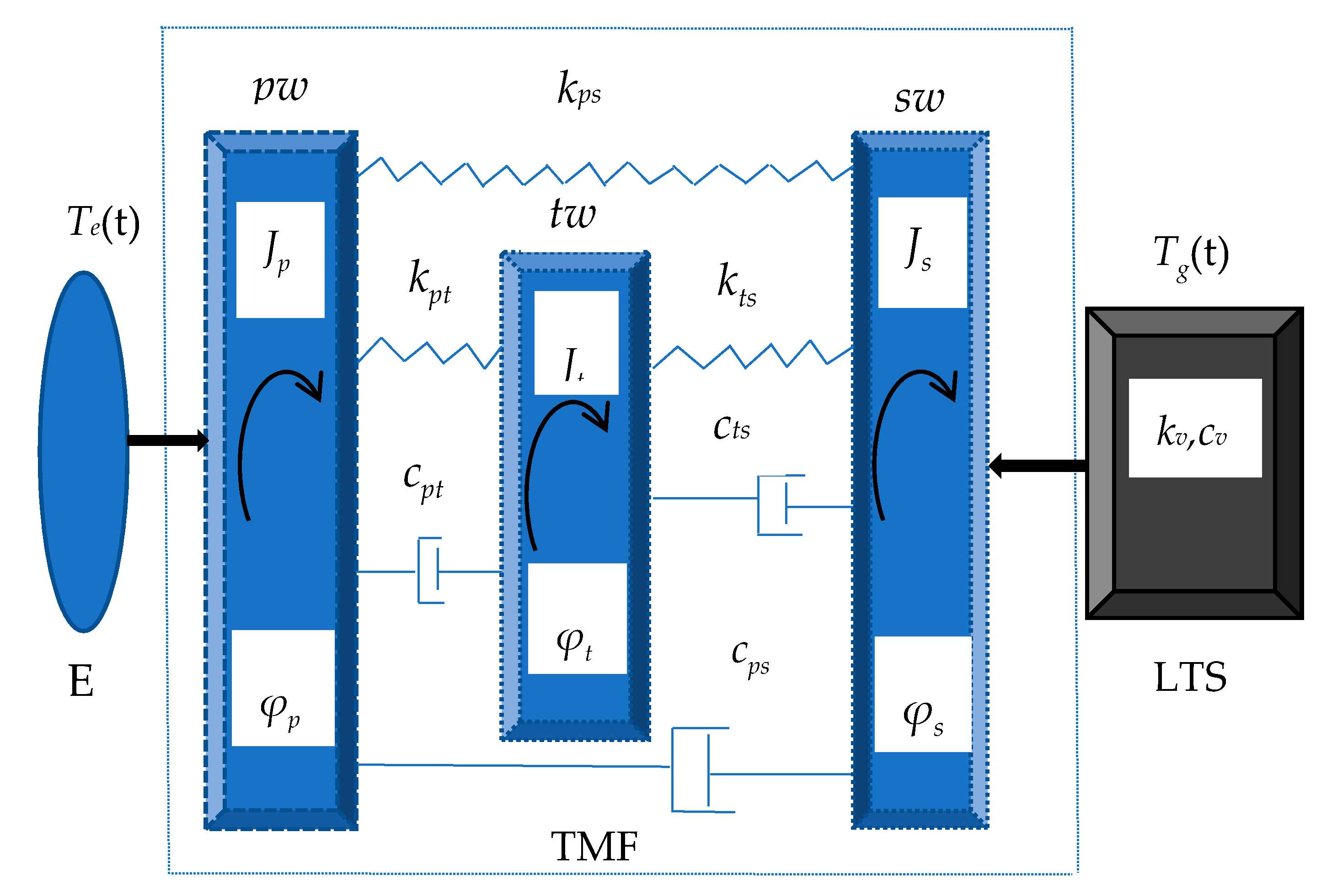
2. Modelling
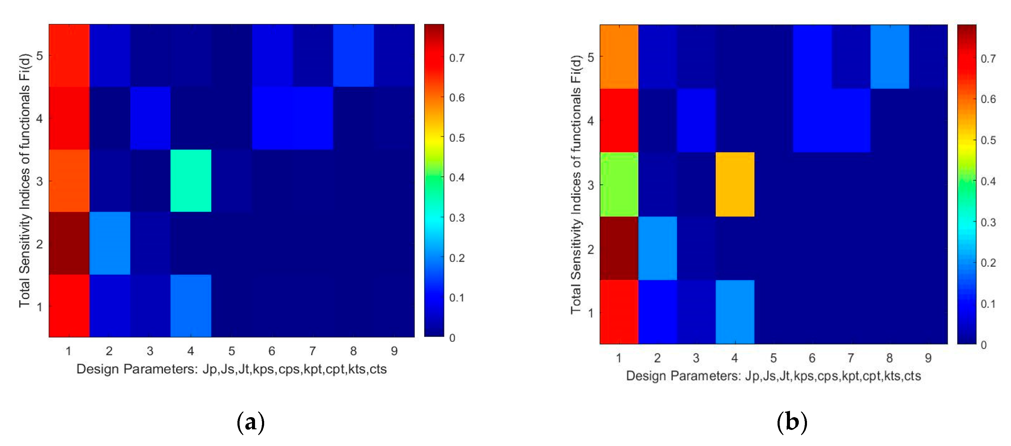
3. Global Sensitivity Analysis
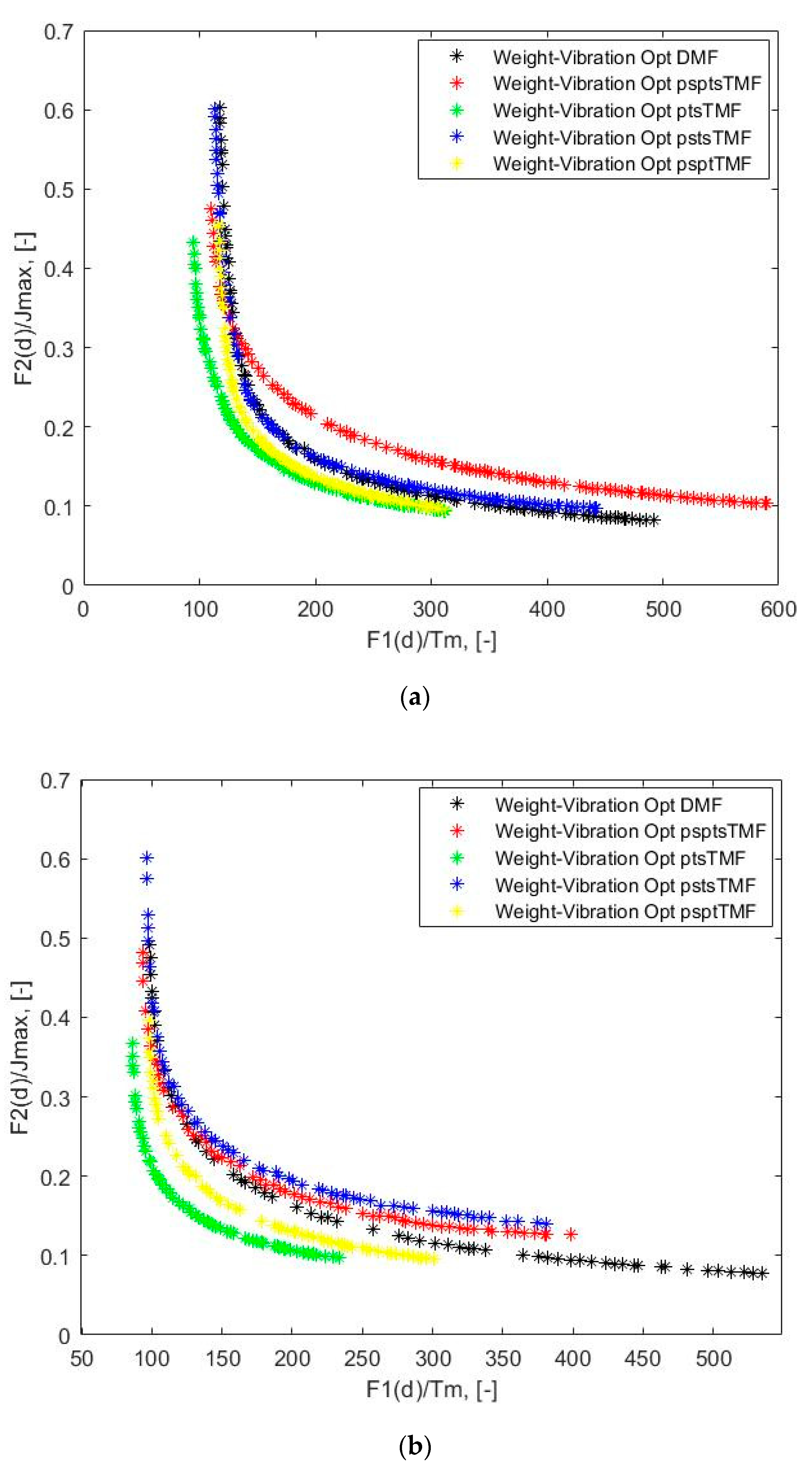
4. Weight-Vibration Pareto Optimization
5. Discussion
6. Conclusions and Outlook
- There exists evidence of feasibility of the application of weight-vibration optimized triple mass flywheels in heavy-duty trucks powertrains.
- For a heavy-duty truck powertrain equipped with a triple mass flywheel, there exists the weight-vibration bi-objective optimized mass inertia, as well as stiffness and damping parameters providing the trade-off between the level of attenuation of the oscillations of the torque at the transmission input shaft and the total mass inertia of the absorber in the operating engine speed range when the third engine order vibration harmonic is in focus.
- The weight-vibration optimized design parameters of a triple mass flywheel providing the best attenuation of oscillations of the torque at the transmission input shaft can put this concept in a superior position in comparison with the weight-vibration optimized dual mass flywheel.
Funding
Conflicts of Interest
References
- Albers, A. Advanced development of dual mass flywheel (DMFW) design-noise control for today’s automobiles. In 5th LuK Symposium; Schaeffler: Bühl, Germany, 1994; pp. 24–41. [Google Scholar]
- Kim, T.H.; Song, H.L.; Hwang, S.H.; Kim, H.S. Analysis of dual mass flywheel using discreet arcspring model. Key Eng. Mater. 2006. [Google Scholar] [CrossRef]
- Mahl, T.; Sawodny, O. Modelling of an automotive dual mass flywheel. In IFAC Proceedings; IFAC: Laxenburg, Austria, 2010; Volume 43, pp. 517–523. [Google Scholar] [CrossRef]
- Song, L.Q.; Zeng, L.P.; Zhang, S.P.; Zhou, J.D.; Niu, H.E. Design and analysis of a dual mass flywheel with continuously variable stiffness based on compensation principle. Mech. Mach. Theory 2014, 79, 124–140. [Google Scholar] [CrossRef]
- Chen, L.; Zeng, R.; Jiang, Z. Nonlinear dynamical model of an automotive dual mass flywheel. Adv. Mech. Eng. 2015, 7, 1–11. [Google Scholar] [CrossRef]
- Fidlin, A.; Mall, P. On the effect of the distributed friction in the arc spring on the dynamic behavior of the automotive transmission. In Proceedings of the International Conference on Engineering Vibrations, ICoEV 2015; National and University Library of Slovenia: Ljubljana, Slovenia, 2015; pp. 1099–1108. [Google Scholar]
- Gupta, K.; Choudhary, A.; Bidre, R. NVH Performance Improvement Study Using a Dual Mass Flywheel (DMF), Inertia Ring Type Tuned Torsional Vibration Damper (TVD) and Single Mass Flywheel (SMF) in a Front Engine and Rear Wheel Driveline Architecture. SAE Tech. Pap. 2017. [Google Scholar] [CrossRef]
- Mall, P.; Fidlin, A.; Krüger, A.; Groß, H. Simulation based optimization of torsional vibration dampers in automotive powertrains. Mech. Mach. Theory 2017, 115, 244–266. [Google Scholar] [CrossRef]
- Faust, H. Powertrain systems of the future—engine, transmission and damper systems for downspeeding, downsizing and cylinder deactivation. In 10th Schaeffler Symposium; Schaeffler Technologies GmbH & Co. KG: Baden-Baden, Germany, 2014; pp. 24–41. [Google Scholar] [CrossRef]
- Haddow, A.; Shaw, S. Centrifugal Pendulum Vibration Absorbers: An Experimental and Theoretical Investigation. Nonlinear Dyn. 2003, 34, 293–307. [Google Scholar] [CrossRef]
- Haris, A.; Motato, E.; Theodossiades, S.; Rahnejat, H.; Kelly, P.; Vakakis, A.; Bergman, L.; McFarland, D.M. A study on torsional vibration attenuation in automotive drivetrains using absorbers with smooth and non-smooth nonlinearities. Appl. Math. Model. 2017, 46, 674–690. [Google Scholar] [CrossRef]
- Kooy, A. Best-in-class dampers for every driveline concept. In Schaeffler Symposium; Schaeffler: Baden-Baden, Germany, 2018; pp. 146–160. [Google Scholar]
- Haris, A.; Motato, E.; Mohammadpour, M.; Thedossiades, S.; Rahnejat, H.; O’ Mahony, M.; Vakakis, A.F.; Bergman, L.A.; McFarland, D.M. On the effect of multiple parallel nonlinear absorbers in palliation of torsional response of automotive drivetrain. Int. J. Non-Linear Mech. 2017, 96, 22–35. [Google Scholar] [CrossRef]
- Motato, E.; Haris, A.; Thedossiades, S.; Mohammadpour, M.; Rahnejat, H.; Kelly, P.; Vakakis, A.F.; McFarland, D.M.; Bergman, L.A. Targeted energy transfer and modal energy redistribution in automotive drivetrains. Nonlinear Dyn. 2017, 87, 169–190. [Google Scholar] [CrossRef]
- Chen, Z.; Chen, Z.; Mao, Y.; Shi, W.; Zhang, G. Control Research of Power Train Torsional Vibration Based on Magneto-Rheological Fluid Dual Mass Flywheel. SAE Tech. Pap. 2014. [Google Scholar] [CrossRef]
- Zu, Q.-h.; Chen, Z.-Y.; Shi, W.-K.; Mao, Y.; Chen, Z.-Y. Torsional Vibration Semiactive Control of Drivetrain Based on Magnetorheological Fluid Dual Mass Flywheel. Math. Probl. Eng. Hindawi Publ. Corp. 2015. [Google Scholar] [CrossRef]
- Dong, X.; Li, W.; Yu, J.; Pan, C.; Xi, J.; Zhou, Y.; Wang, X. Magneto-Rheological Variable Stiffness and Damping Torsional Vibration Control of Powertrain System. Front. Mater. 2020. [Google Scholar] [CrossRef]
- Wramner, L.; Berbyuk, V.; Johansson, H. Vibration dynamics in non-linear dual mass flywheels for heavy-duty trucks. In The 28th Edition of the Biennial ISMA Conference on Noise and Vibration Engineering; KU Leuven: Leuven, Belgium, 2018; pp. 1863–1876. [Google Scholar]
- Berbyuk, V. Design optimization of torsional vibration absorbers for heavy-duty truck drivetrain systems. Vibration 2019, 2, 240–264. [Google Scholar] [CrossRef]
- Berbyuk, V. Weight-vibration Pareto optimization of a dual mass flywheel. Math. Methods Phys. Fields 2019, 62, 7–18. [Google Scholar]
- Berbyuk, V. Towards the limits of vibration attenuation in drivetrain system by torsional dynamics absorber. In Advances in Dynamics of Vehicles on Roads and Tracks. IAVSD 2019; Klomp, M., Bruzelius, F., Nielsen, J., Hillemyr, A., Eds.; Lecture Notes in Mechanical Engineering; Springer: Berlin/Heidelberg, Germany, 2020; pp. 1574–1583. [Google Scholar] [CrossRef]
- Wramner, L. Dual mass flywheel with tuned vibration absorbers for application in heavy-duty truck powertrains. Proc. Inst. Mech. Eng. Part D J. Automob. Eng. 2020. [Google Scholar] [CrossRef]
- Wramner, L. Analysis of power split vibration absorber performance in heavy-duty truck powertrains. Proc. Inst. Mech. Eng. Part D J. Automob. Eng. 2020. [Google Scholar] [CrossRef]
- Wramner, L. Torsional Vibration Absorbers in Heavy-Duty Truck Powertrains. Ph.D. Thesis, Chalmers University of Technology, Göteborg, Sweden, 2020. [Google Scholar]
- Den Hartog, J.P. Mechanical Vibrations; Dover Publication, Inc.: New York, NY, USA, 1985. [Google Scholar]
- De Domenico, D.; Ricciardi, G. Optimal design and seismic performance of tuned mass damper inerter (TMDI) for structures with nonlinear base isolation systems. Earthq. Eng. Struct. Dyn. 2018, 47, 2539–2560. [Google Scholar]
- Mousavi Bideleh, S.M.; Berbyuk, V. Pareto Optimization of a Nonlinear Tuned Mass Damper to Control Vibrations in Hand Held Impact Machines. In Nonlinear Dynamics, Volume 1. Conference Proceedings of the Society for Experimental Mechanics Series; Kerschen, G., Ed.; Springer: Berlin/Heidelberg, Germany, 2019; pp. 27–44. [Google Scholar] [CrossRef]
- Seer, T.A.; Vahdati, N.; Shiryaev, O. Adaptive Torsional Tuned Vibration Absorber for Rotary Equipment. Vibration 2019, 2, 116–134. [Google Scholar] [CrossRef]
- Karimaei, H.; Mehrgou, M.; Chamani, H.R. Optimisation of torsional vibration system for a heavy-duty inline six-cylinder diesel engine. Proc Imeche Part K J. Multi-Body Dyn. 2019, 233, 642–656. [Google Scholar] [CrossRef]
- Bazara, S.; Shetty, C. Nonlinear Programming. Theory and Algorithms; John Wiley and Sons: New York, NY, USA, 1979. [Google Scholar]
- Bagchi, T.P. Multiobjective Scheduling by Genetic Algorithmsii; Kluwer Academic Publisher: Boston, MA, USA, 1999. [Google Scholar]
- Tan, X.; Hua, L.; Lu, C.; Yang, C.; Wang, Y.; Wang, S. A new method for optimizing the parameters of torsional vibration dampers. J. Vibroeng. 2017, 19, 4155–4171. [Google Scholar]
- McCall, J. Genetic algorithms for modelling and optimization. J. Comput. Appl. Math. 2005, 184, 205–222. [Google Scholar] [CrossRef]
- Maeda, Y.; Nishiwaki, S.; Izui, K.; Yoshimura, M.; Matsui, K.; Terada, K. Structural topology optimization of vibrating structures with specified eigenfrequencies and eigenmode shapes. Int. J. Numer. Methods Eng. 2006, 67, 597–628. [Google Scholar] [CrossRef]
- Chronopoulos, D. Design optimization of composite structures operating in acoustic environments. J. Sound Vib. 2015, 355, 322–344. [Google Scholar] [CrossRef]
- Kaveh, A.; Ghazaan, M.I. Vibrating particles system algorithm for truss optimization with multiple natural frequency constraints. Acta Mech. 2017, 218, 307–322. [Google Scholar] [CrossRef]
- Shaw, W.L. Triple Mass Flywheel. U.S. Patent 2019/0011010 A1, 10 January 2019. [Google Scholar]
- Olsson, H. Control Systems with Friction. Ph.D. Thesis, Lund Institute of Technology, Göteborg, Sweden, 1996. [Google Scholar]
- Zhang, X.; Pandey, M.D. An effective approximation for variance-based global sensitivity analysis. Reliab. Eng. Syst. Saf. 2014, 121, 164–174. [Google Scholar] [CrossRef]
- Rabitz, H.; Alis, Ö. General foundations of high-dimensional model representations. J. Math. Chem. 1999, 25, 197–233. [Google Scholar] [CrossRef]
- Mousavi Bideleh, S.M.; Berbyuk, V. Global sensitivity analysis of bogie dynamics with respect to suspension components. Multibody Syst. Dyn. 2016, 37, 145–174. [Google Scholar] [CrossRef]
- Mousavi Bideleh, S.M.; Berbyuk, V. A Computer Code for Sensitivity Analysis and Multiobjective Optimization: SAMO Tutorial; Department of Mechanics and Maritime Sciences, Chalmers University of Technology: Gothenburg, Sweden, 2017; p. 45. [Google Scholar]
- Karlsson, J. Investigation of Dynamic Friction Properties of a Dual Mass Flywheel for Commercial Vehicles. Master’s Thesis, Chalmers University of Technology, Göteborg, Sweden, 2018. [Google Scholar]


| psptsTMF | psptTMF (kts = cts = 0) | pstsTMF (kpt = cpt = 0) | ptsTMF (kps = cps = 0) | DMF Jt = 0 | |
|---|---|---|---|---|---|
| , (kgm2) | 1.48 | 1.67 | 1.98 | 1.50 | 2.34 |
| , (kgm2) | 0.11 | 0.10 | 0.10 | 0.11 | 0.10 |
| , (kgm2) | 0.34 | 0.08 | 0.35 | 0.14 | - |
| , (Nm/rad) | 2683 | 3132 | 3165 | - | 3938 |
| , (Nms/rad) | 18 | 21 | 27 | - | 30 |
| , (Nm/rad) | 6216 | 7399 | - | 3033 | - |
| , (Nms/rad) | 12 | 74 | - | 91 | - |
| , (Nm/rad) | 2764 | - | 7502 | 4995 | - |
| , (Nms/rad) | 12 | - | 29 | 9 | - |
| , (-) | 110 | 117 | 114 | 95 | 118 |
| , (kgm2) | 1.93 | 1.85 | 2.43 | 1.75 | 2.44 |
| psptsTMF | psptTMF (kts = cts = 0) | pstsTMF (kpt = cpt = 0) | ptsTMF (kps = cps = 0) | DMF Jt = 0 | |
|---|---|---|---|---|---|
| , (kgm2) | 1.44 | 1.43 | 1.98 | 1.30 | 1.88 |
| , (kgm2) | 0.11 | 0.11 | 0.10 | 0.11 | 0.11 |
| , (kgm2) | 0.40 | 0.07 | 0.35 | 0.08 | - |
| , (Nm/rad) | 2843 | 3201 | 3334 | - | 3069 |
| , (Nms/rad) | 25 | 25 | 37 | - | 33 |
| , (Nm/rad) | 6332 | 7190 | - | 4309 | - |
| , (Nms/rad) | 17 | 71 | - | 124 | - |
| , (Nm/rad) | 3786 | - | 7349 | 5142 | - |
| , (Nms/rad) | 18 | - | 29 | 14 | - |
| , (-) | 94 | 98 | 96 | 86 | 99 |
| , (kgm2) | 1.94 | 1.61 | 2.43 | 1.49 | 1.99 |
© 2020 by the author. Licensee MDPI, Basel, Switzerland. This article is an open access article distributed under the terms and conditions of the Creative Commons Attribution (CC BY) license (http://creativecommons.org/licenses/by/4.0/).
Share and Cite
Berbyuk, V. Weight-Vibration Pareto Optimization of a Triple Mass Flywheel for Heavy-Duty Truck Powertrains. Machines 2020, 8, 50. https://doi.org/10.3390/machines8030050
Berbyuk V. Weight-Vibration Pareto Optimization of a Triple Mass Flywheel for Heavy-Duty Truck Powertrains. Machines. 2020; 8(3):50. https://doi.org/10.3390/machines8030050
Chicago/Turabian StyleBerbyuk, Viktor. 2020. "Weight-Vibration Pareto Optimization of a Triple Mass Flywheel for Heavy-Duty Truck Powertrains" Machines 8, no. 3: 50. https://doi.org/10.3390/machines8030050
APA StyleBerbyuk, V. (2020). Weight-Vibration Pareto Optimization of a Triple Mass Flywheel for Heavy-Duty Truck Powertrains. Machines, 8(3), 50. https://doi.org/10.3390/machines8030050