ADRC-Based Robust and Resilient Control of a 5-Phase PMSM Driven Electric Vehicle


 ,
, 
 and
and
Abstract
1. Introduction
2. Electric Vehicle Modeling
2.1. Mechanical Part
2.2. 5-Phase PMSM Modeling
3. Active Disturbance Rejection Controller
3.1. Resilient Control
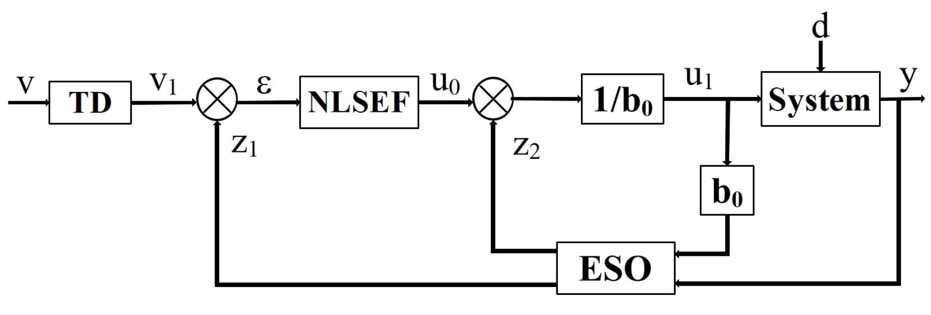
3.2. Nonlinear ADRC Design
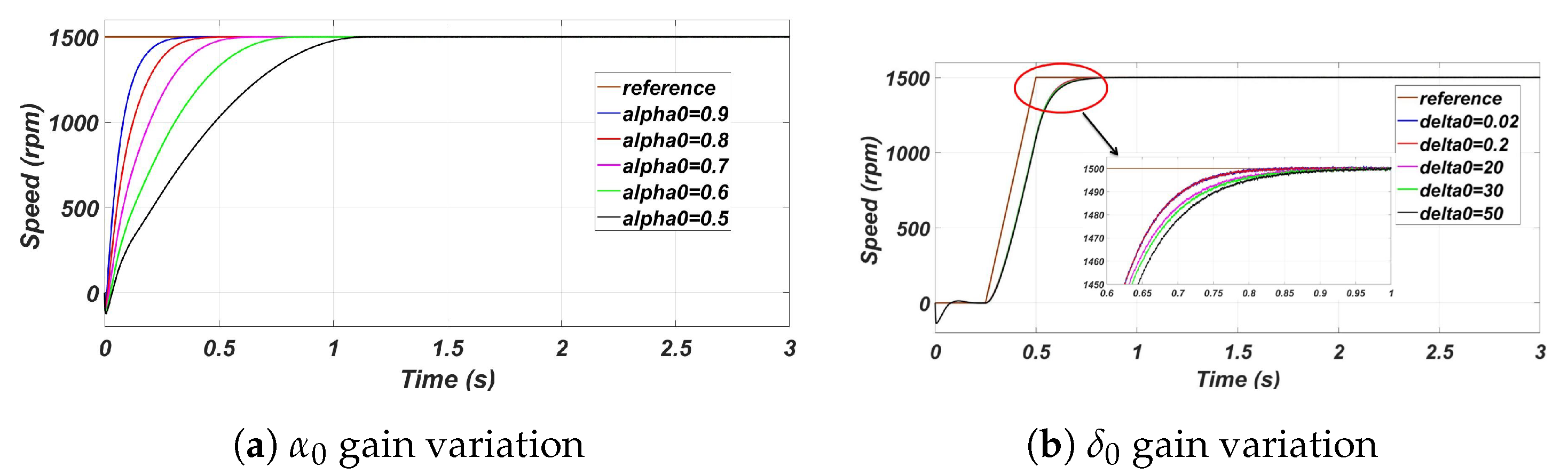
3.2.1. Nonlinear Function Design
3.2.2. TD Design
3.2.3. ESO Design
3.2.4. NLSEF Design
3.3. Linear ADRC Design
3.4. Stability Analysis
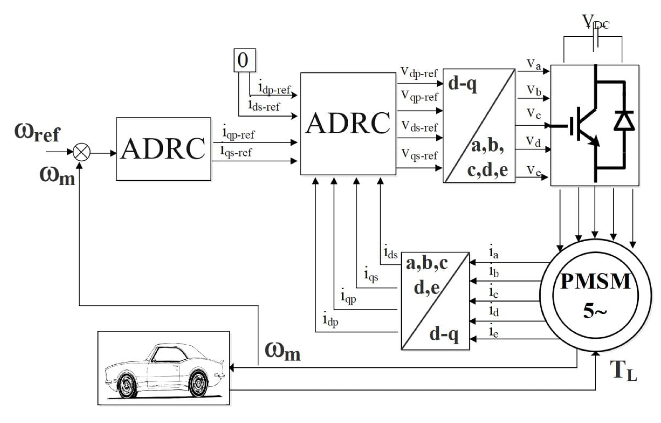
4. ADRC Design for 5-Phase PMSM
4.1. Speed Controller Design
4.2. ADRC Controller Current Loop
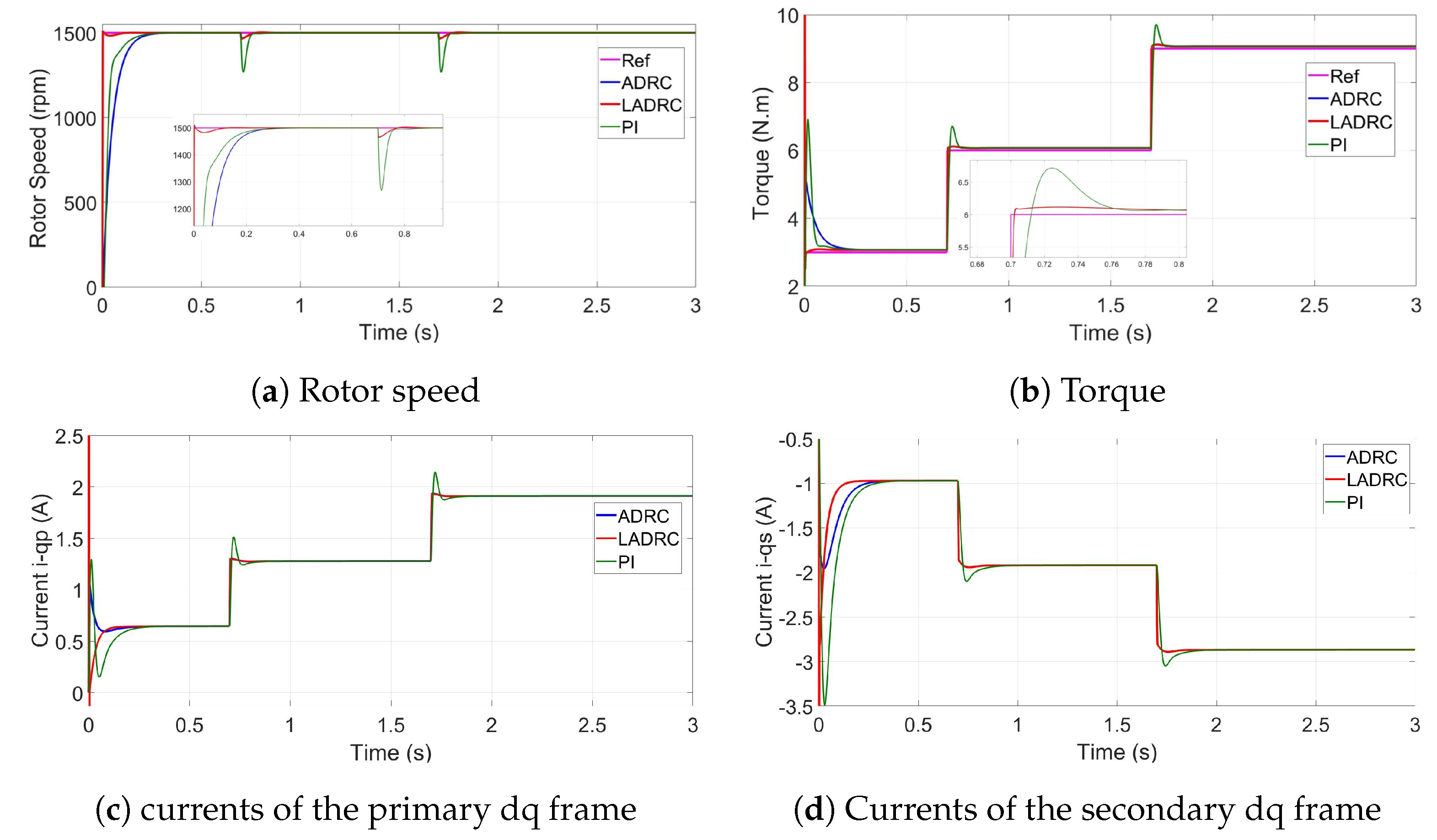
5. Simulation Results
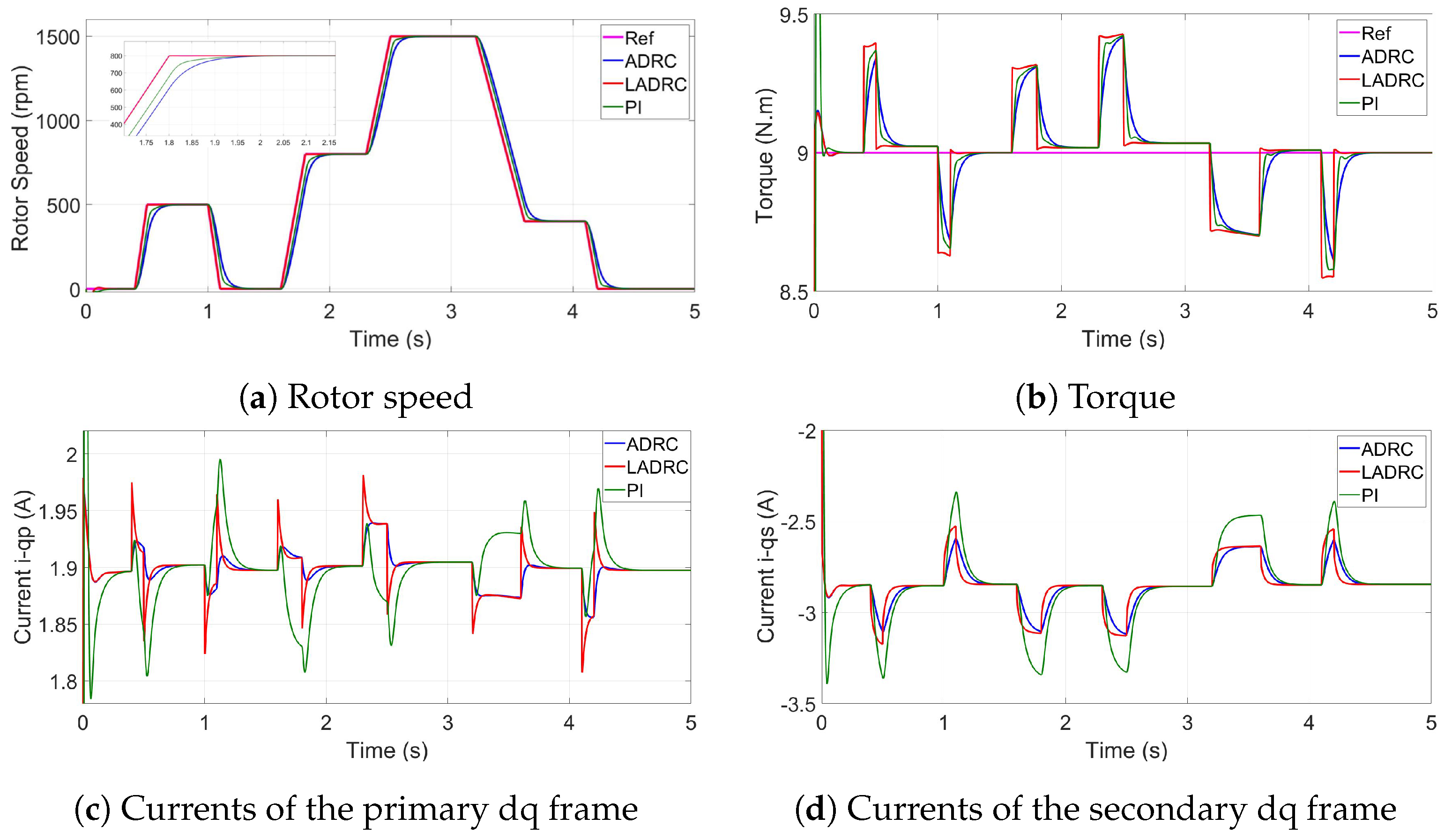
5.1. Speed and Load Torque Variation
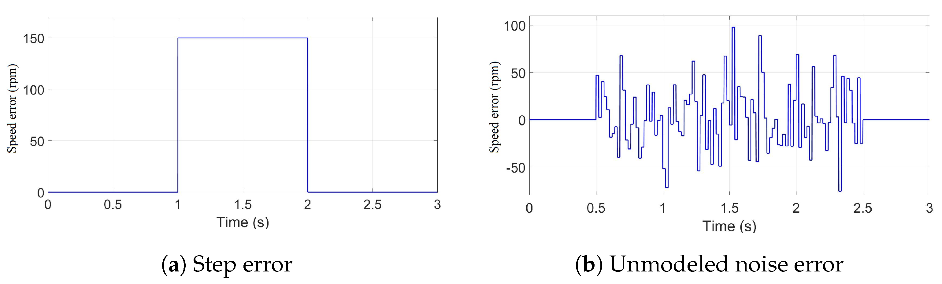
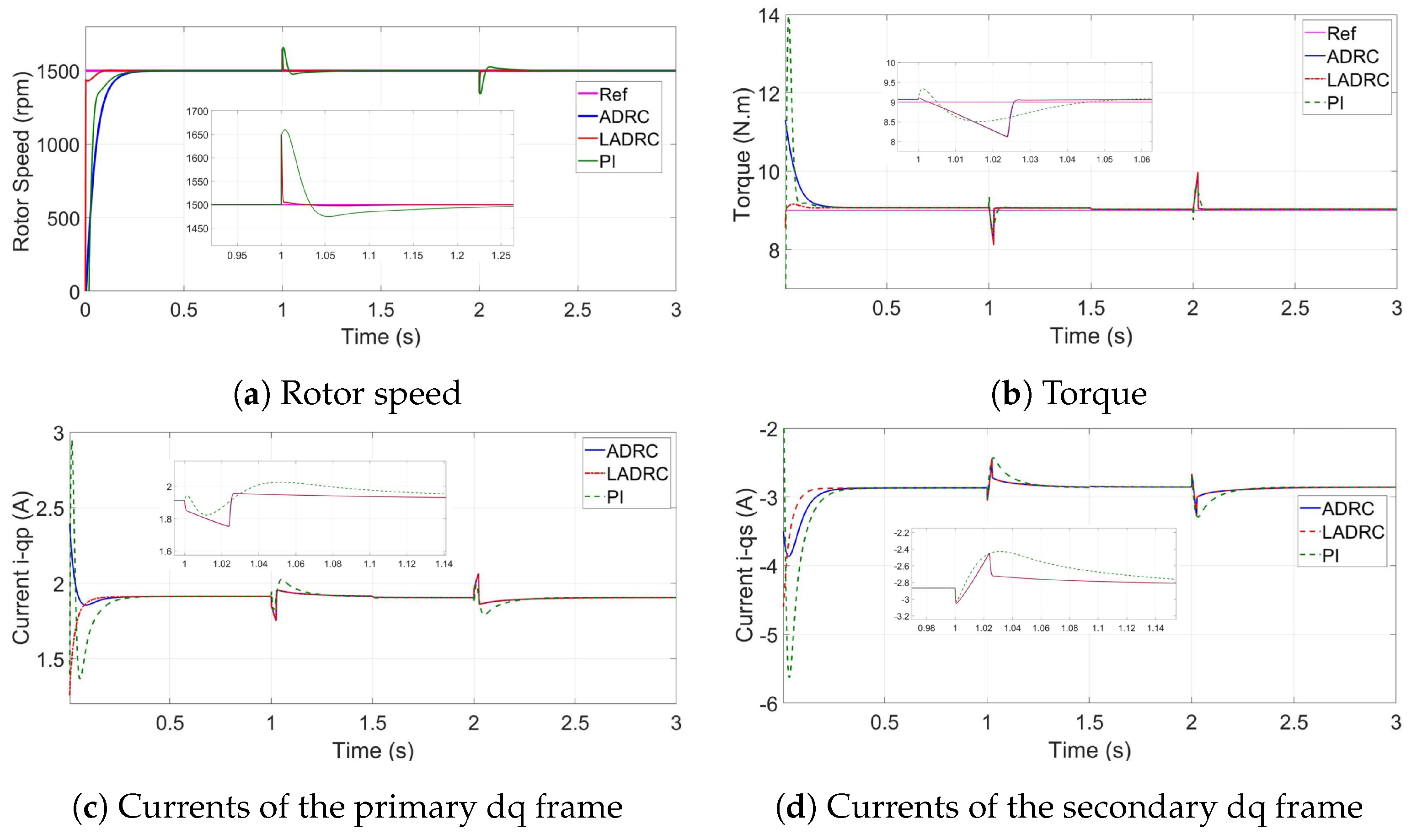
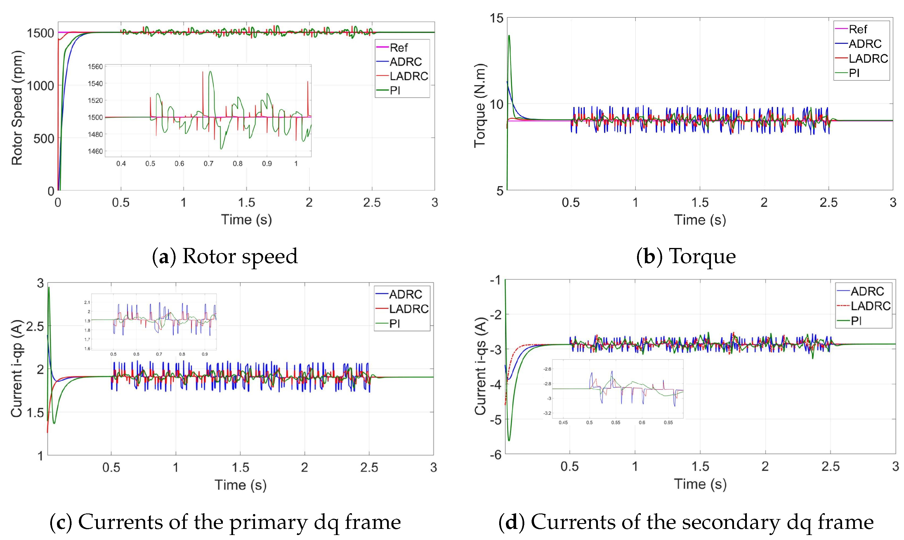
5.2. Speed Sensor Failure
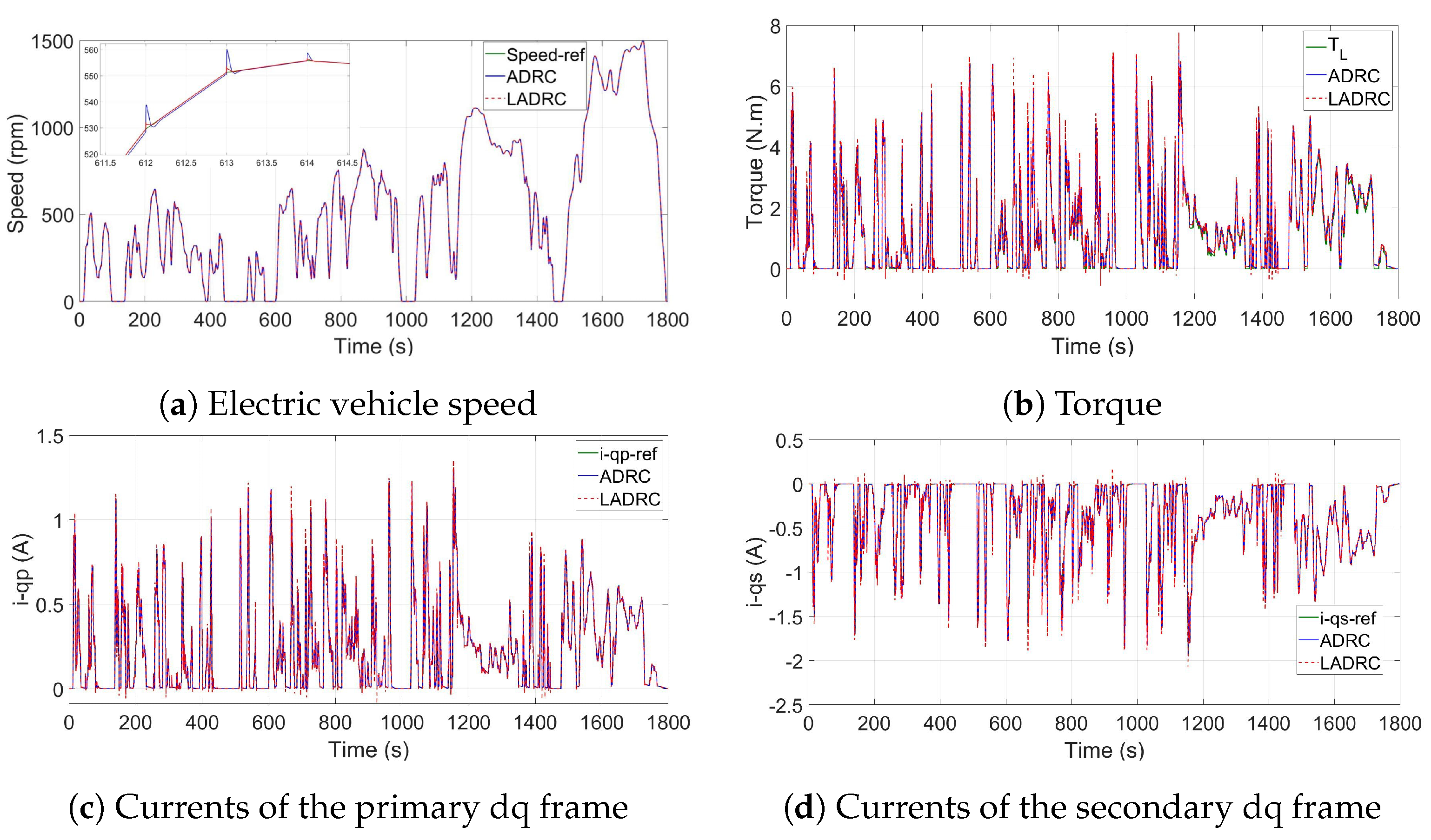
5.3. Simulation Results Using Driving Cycles
6. Conclusions
Author Contributions
Funding
Acknowledgments
Conflicts of Interest
Nomenclature
| p, s | primary and secondary fictitious machine, respectively, in the dq frame., | Linear Active Disturbance Rejection Controller. | |||
| v | Stator voltage, | Torque of wheel. | |||
| i | Stator currents, | Torque of motor. | |||
| Electromagnetic torque, | Efficiency coefficient. | ||||
| L | Virtual machine inductance, | Gear ratio. | |||
| V | Driving velocity, | Electric Vehicle. | |||
| a | Vehicle acceleration, | Tracking Differentiator. | |||
| Rolling resistance force, | Extended State Observer. | ||||
| Acceleration force, | Non-Linear State Error Feedback. | ||||
| Aerodynamic drag force, | Permanent Magnet Synchronous Motor. | ||||
| Rotational speed of wheel, | Active Disturbance Rejection Controller. | ||||
| Rotational speed of motor, |
References
- Hezzi, A.; Elghali, S.B.; Salem, Y.B.; Abdelkrim, M.N. Control of five-phase PMSM for electric vehicle application. In Proceedings of the 2017 18th International Conference onSciences and Techniques of Automatic Control and Computer Engineering (STA), Monastir, Tunisia, 21–23 December 2017; pp. 205–211. [Google Scholar]
- Mekri, F.; Ben Elghali, S.; Charpentier, J.F.; Kestelyn, X.; Benbouzid, M. A New Control Strategy of 5-Phase PM Motor under Open-Circuited Phase Based on High Order Sliding Mode and Current References Real-Time Generation. Electr. Power Components Syst. 2019, 47, 261–274. [Google Scholar] [CrossRef]
- Mekri, F.; Elghali, S.B.; Charpentier, J.F. Analysis, simulation and experimental strategies of 5-phase permanent magnet motor control. Arch. Electr. Eng. 2019, 68, 629–641. [Google Scholar]
- Hezzi, A.; Bensalem, Y.; Zerrougui, M.; Elghali, S.B.; Abdelkrim, M.N. Sensorless Control Strategy for Five-Phase PMSM based on UIO for Linear Parameter Varying System. In Proceedings of the 2020 17th International Multi-Conference on Systems, Signals & Devices (SSD), Rabat-Salé, Morocco, 4–7 March 2020. [Google Scholar]
- Han, J. From PID to active disturbance rejection control. IEEE Trans. Ind. Electron. 2009, 56, 900–906. [Google Scholar] [CrossRef]
- Herbst, G. Simulative Study on Active Disturbance Rejection Control (ADRC) as a Control Tool for Practitioners. Electronics 2012, 2, 246–279. [Google Scholar] [CrossRef]
- Zhou, Z.; Ben Elghali, S.; Benbouzid, M.; Amirat, Y.; Elbouchikhi, E.; Feld, G. Control Strategies for Tidal Stream Turbine Systems – A Comparative Study of ADRC, PI, and High-Order Sliding Mode Controls. In Proceedings of the (IES), IECON 2019 45th Annual Conference of the IEEE Industrial Electronics Society, Lisbon, Portugal, 14–17 October 2019. [Google Scholar]
- Feng, G.; Liu, Y.F.; Huang, L. A new robust algorithm to improve the dynamic performance on the speed control of induction motor drive. IEEE Trans. Power Electron. 2004, 19, 1614–1627. [Google Scholar] [CrossRef]
- Zhang, C.; Chen, Y. Tracking control of ball screw drives using ADRC and equivalent-error-model-based feedforward control. IEEE Trans. Ind. Electron. 2016, 63, 7682–7692. [Google Scholar] [CrossRef]
- Lei, P.; Liao, X.B.; Huang, L.H.; Gong, C.H. Research of ADRC in Application to the Servo System of Self-propelled Gun. Appl. Mech. Mater. 2015, 713, 730–733. [Google Scholar] [CrossRef]
- Zhou, X.; Cui, H.; Ma, Y.; Gao, Z. The research on energy conservation controller for asynchronous motor based on ADRC. In Proceedings of the 2017 29th Chinese Control And Decision Conference (CCDC), Chongqing, China, 28–30 May 2017; pp. 4010–4014. [Google Scholar]
- Kuang, Z.; Du, B.; Cui, S.; Chan, C. Speed Control of Load Torque Feedforward Compensation Based on Linear Active Disturbance Rejection for Five-Phase PMSM. IEEE Access 2019, 7, 159787–159796. [Google Scholar] [CrossRef]
- Ren, L.; Mao, C.; Song, Z.; Liu, F. Study on active disturbance rejection control with actuator saturation to reduce the load of a driving chain in wind turbines. Renew. Energy 2019, 133, 268–274. [Google Scholar] [CrossRef]
- Ortiz, A.; Orozco, S.; Zannatha, I. ADRC controller for weightlifter Humanoid robot. In Proceedings of the 2019 International Conference on Electronics, Communications and Computers (CONIELECOMP), Cholula, Mexico, 27 February–1 March 2019; pp. 41–46. [Google Scholar]
- Hezzi, A.; Ben Elghali, S.; Bensalem, Y.; Zhou, Z.; Benbouzid, M.; Abdelkrim, M.N. Active Disturbance Rejection Control of a Five-Phase PMSM with Parameters Variation. In Proceedings of the (IES), IECON 2019 45th Annual Conference of the IEEE Industrial Electronics Society, Lisbon, Portugal, 14–17 October 2019. [Google Scholar]
- Sira-Ramírez, H.; Linares-Flores, J.; García-Rodríguez, C.; Contreras-Ordaz, M.A. On the control of the permanent magnet synchronous motor: An active disturbance rejection control approach. IEEE Trans. Control. Syst. Technol. 2014, 22, 2056–2063. [Google Scholar] [CrossRef]
- Rong, Z.l.; Huang, Q. A new PMSM speed modulation system with sliding mode based on active-disturbance-rejection control. J. Cent. South Univ. 2016, 23, 1406–1415. [Google Scholar] [CrossRef]
- Yuan, Q.; Liu, Z.; Chen, H.; Tian, Y. A cruise control for electric vehicle based on ADRC controller considering driver’s behavior. In Proceedings of the IECON 2017-43rd Annual Conference of the IEEE Industrial Electronics Society, Beijing, China, 29 October–1 November 2017; pp. 4597–4602. [Google Scholar]
- Wen, J.P.; Zhang, C.W. Research on modeling and control of regenerative braking for brushless DC machines driven electric vehicles. Math. Probl. Engi. 2015, 2015. [Google Scholar] [CrossRef]
- Lin, D.; Luo, W.; Zhang, H. Active disturbance rejection controller of BLDCM in electric vehicle. In Proceedings of the 2011 International Conference on Electrical Machines and Systems, Beijing, China, 20–23 August 2011; pp. 1–4. [Google Scholar]
- Byington, C.S.; Watson, M.; Edwards, D.; Stoelting, P. A model-based approach to prognostics and health management for flight control actuators. In Proceedings of the 2004 IEEE Aerospace Conference Proceedings (IEEE Cat. No. 04TH8720), Big Sky, MT, USA, 6–13 March 2004; pp. 3551–3562. [Google Scholar]
- Tabbache, B.; Rizoug, N.; Benbouzid, M.; Kheloui, A. A control reconfiguration strategy for post-sensor FTC in induction motor-Based EVs. IEEE Trans. Veh. Technol. 2013, 62, 965–971. [Google Scholar] [CrossRef][Green Version]
- Tabbache, B.; Benbouzid, M.; Kheloui, A.; Bourgeot, J. DSP-based sensor fault detection and post fault-tolerant control of an induction motor-based electric vehicle. Int. J. Veh. Technol. 2012, 2012, 1–7. [Google Scholar] [CrossRef]
- Trabelsi, M.; Boussak, M.; Benbouzid, M. Multiple criteria for high performance real-time diagnostic of single and multiple open-switch faults in AC-motor drives: Application to IGBT-based voltage source inverter. Electr. Power Syst. Res. 2017, 144, 136–149. [Google Scholar] [CrossRef]
- Pham, H.T.; Bourgeot, J.M.; Benbouzid, M. Comparative investigations of sensor fault-tolerant control strategies performance for marine current turbine applications. IEEE J. Ocean. Eng. 2018, 43, 1024–1036. [Google Scholar] [CrossRef]
- Bolvashenkov, I.; Herzog, H.G.; Ismagilov, F.; Vavilov, V.; Khvatskin, L.; Frenkel, I.; Lisnianski, A. Fault Tolerant Multi-phase Permanent Magnet Synchronous Motor for the More Electric Aircraft. In Fault-Tolerant Traction Electric Drives; Springer: Berlin, Germany, 2020; pp. 73–92. [Google Scholar]
- Nounou, K.; Charpentier, J.; Marouani, K.; Benbouzid, M.; Kheloui, A. Emulation of an electric naval propulsion system based on a multiphase machine under healthy and faulty operating conditions. IEEE Trans. Veh. Technol. 2018, 67, 6895–6905. [Google Scholar] [CrossRef]
- Song, Z.; Li, J.; Ouyang, M.; Gu, J.; Feng, X.; Lu, D. Rule-based fault diagnosis of hall sensors and fault-tolerant control of PMSM. Chin. J. Mech. Eng. 2013, 26, 813–822. [Google Scholar] [CrossRef]
- Deng, F.; Guan, Y. PMSM Vector Control Based on Improved ADRC. In Proceedings of the 2018 IEEE International Conference of Intelligent Robotic and Control Engineering (IRCE), Lanzhou, China, 24–27 August 2018; pp. 154–158. [Google Scholar]
- Du, B.; Wu, S.; Han, S.; Cui, S. Application of linear active disturbance rejection controller for sensorless control of internal permanent-magnet synchronous motor. IEEE Trans. Ind. Electron. 2016, 63, 3019–3027. [Google Scholar] [CrossRef]
- Ahi, B.; Haeri, M. Linear active disturbance rejection control from the practical aspects. Ieee/Asme Trans. Mechatronics 2018, 23, 2909–2919. [Google Scholar] [CrossRef]
- Hezzi, A.; Bensalem, Y.; Elghali, S.B.; Abdelkrim, M.N. Sliding Mode Observer based sensorless control of five phase PMSM in electric vehicle. In Proceedings of the 2019 19th International Conference on Sciences and Techniques of Automatic Control and Computer Engineering (STA), Sousse, Tunisia, 24–26 March 2019; pp. 530–535. [Google Scholar]
- Zheng, Q. On Active Disturbance Rejection Control; Stability Analysis and Applications in Disturbance Decoupling Control. Ph.D. Thesis, Cleveland State University, Cleveland, OH, USA, July 2009. [Google Scholar]
- Zheng, Q.; Chen, Z.; Gao, Z. A practical approach to disturbance decoupling control. Control. Eng. Pract. 2009, 17, 1016–1025. [Google Scholar] [CrossRef]
- Moujahed, M.; Azza, H.B.; Frifita, K.; Jemli, M.; Boussak, M. Fault detection and fault-tolerant control of power converter fed PMSM. Electr. Eng. 2016, 98, 121–131. [Google Scholar] [CrossRef]
- Lei, Y.; Xu, J.; Hao, Q. Application of ADRC in Stability Control of Tank Gun System. In Proceedings of the 2018 IEEE 7th Data Driven Control and Learning Systems Conference (DDCLS), Enshi, China, 25–27 May 2018; pp. 670–675. [Google Scholar]
- Qiu, Z.; Xiao, J.; Wang, S. Active-disturbance rejection control based on a novel sliding mode observer for PMSM speed and rotor position. J. Vibroeng. 2015, 17, 4603–4617. [Google Scholar]
- Hezzi, A.; Ben Elghali, S.; Zhou, Z.; Elbouchikhi, E.; Benbouzid, M. Linear ADRC for Speed Control of 5-Phase PMSM-based Electric Vehicles. In Proceedings of the 2020 International Conference on Electrical and Technologies, ICEIT, Rabat-Salé, Morocco, 4–7 March 2020. [Google Scholar]
- Zhao, L.; Yang, Y.; Xia, Y.; Liu, Z. Active disturbance rejection position control for a magnetic rodless pneumatic cylinder. IEEE Trans. Ind. Electron. 2015, 62, 5838–5846. [Google Scholar] [CrossRef]
- Zheng, Q.; Gaol, L.Q.; Gao, Z. On stability analysis of active disturbance rejection control for nonlinear time-varying plants with unknown dynamics. In Proceedings of the 2007 46th IEEE Conference on Decision and Control, New Orleans, LA, USA, 12–14 December 2007; pp. 3501–3506. [Google Scholar]
- Gao, Z. Active disturbance rejection control: A paradigm shift in feedback control system design. In Proceedings of the 2006 American control conference, Minneapolis, MN, USA, 4–16 June 2006. [Google Scholar]
- Guo, B.; Bacha, S.; Alamir, M. A review on ADRC based PMSM control designs. In Proceedings of the IECON 2017-43rd annual conference of the IEEE industrial electronics society, Beijing, China, 29 October–1 November 2017; pp. 1747–1753. [Google Scholar]
- Zhou, Z.; Elghali, S.B.; Benbouzid, M.; Amirat, Y.; Elbouchikhi, E.; Feld, G. Tidal stream turbine control: An active disturbance rejection control approach. Ocean. Eng. 2020, 202, 107190. [Google Scholar] [CrossRef]
- Almabrok, A.; Psarakis, M.; Dounis, A. Fast Tuning of the PID Controller in An HVAC System Using the Big Bang–Big Crunch Algorithm and FPGA Technology. Algorithms 2018, 11, 146. [Google Scholar] [CrossRef]
- Cubito, C.; Millo, F.; Boccardo, G.; Di Pierro, G.; Ciuffo, B.; Fontaras, G.; Serra, S.; Otura Garcia, M.; Trentadue, G. Impact of Different Driving Cycles and Operating Conditions on CO2 Emissions and Energy Management Strategies of a Euro-6 Hybrid Electric Vehicle. Energies 2017, 10, 1590. [Google Scholar] [CrossRef]
- Bodisco, T.; Zare, A. Practicalities and Driving Dynamics of a Real Driving Emissions (RDE) Euro 6 Regulation Homologation Test. Energies 2019, 12, 2306. [Google Scholar] [CrossRef]


| Symbol | Parameter | Value |
|---|---|---|
| Number of pole pairs | 2 | |
| R | Stator resistance | |
| Principal machine inductance | 0.1228 H | |
| Seconder machine inductance | 0.0222 H | |
| First harmonic constants | 2 | |
| Third harmonic constants | ||
| J | Inertia moment | kg·m |
| B | Viscous friction coefficient | 0.000457 N.m.s/rad |
| Symbol | Parameter | Value |
|---|---|---|
| Rolling resistance coefficient | ||
| m | Mass of the EV | 1000 kg |
| Air density | 1.2 kg/m | |
| Frontal area | m | |
| Drag coefficient | ||
| g | Gravity acceleration | 9.81 m/s2 |
| r | Tyre radius | 0.3 m |
| Starting Stage | Torque Disturbance | Speed Variation | ||
|---|---|---|---|---|
| LADRC | IAE | 0.0207 | 1.3897 | 0.4374 |
| ISE | 0.0072 | 30.645 | 1.1128 | |
| ITAE | 0.0043 | 1.0190 | 0.2112 | |
| ITSE | 0.0013 | 22.003 | 0.5233 | |
| ADRC | IAE | 2.2360 | 1.4314 | 24.242 |
| ISE | 54.016 | 32.315 | 3406.7 | |
| ITAE | 0.4780 | 1.0497 | 12.068 | |
| ITSE | 10.325 | 23.205 | 1655.4 | |
| PI | IAE | 1.4552 | 6.8994 | 15.557 |
| ISE | 19.674 | 1065.1 | 1521.2 | |
| ITAE | 0.3210 | 5.0133 | 7.5860 | |
| ITSE | 3.8406 | 763.27 | 720.50 |
| Starting Stage | Torque Disturbance | Speed Variation | ||
|---|---|---|---|---|
| LADRC | IAE | 0.0188 | 0.1280 | 0.0053 |
| ISE | 0.0060 | 0.0802 | 0.00017 | |
| ITAE | 0.00067 | 0.0770 | 0.0024 | |
| ITSE | 0.00011 | 0.0481 | 0.00007 | |
| ADRC | IAE | 0.0113 | 0.1280 | 0.0037 |
| ISE | 0.0017 | 0.0802 | 0.00004 | |
| ITAE | 0.00075 | 0.0770 | 0.0018 | |
| ITSE | 0.00003 | 0.0481 | 0.00002 | |
| PI | IAE | 0.0472 | 0.1367 | 0.0115 |
| ISE | 0.0160 | 0.0821 | 0.00062 | |
| ITAE | 0.0037 | 0.0834 | 0.0062 | |
| ITSE | 0.0008 | 0.0495 | 0.00033 |
| Starting Stage | Torque Disturbance | Speed Variation | ||
|---|---|---|---|---|
| LADRC | IAE | 0.0562 | 0.1930 | 0.0332 |
| ISE | 0.0509 | 0.1811 | 0.0080 | |
| ITAE | 0.0021 | 0.1162 | 0.0156 | |
| ITSE | 0.0010 | 0.1087 | 0.0037 | |
| ADRC | IAE | 0.0957 | 0.1931 | 0.0329 |
| ISE | 0.0642 | 0.1811 | 0.0054 | |
| ITAE | 0.0069 | 0.1163 | 0.0170 | |
| ITSE | 0.0031 | 0.1087 | 0.0027 | |
| PI | IAE | 0.1942 | 0.2137 | 0.0637 |
| ISE | 0.2933 | 0.1896 | 0.0212 | |
| ITAE | 0.0139 | 0.1317 | 0.0329 | |
| ITSE | 0.0137 | 0.1148 | 0.0107 |
© 2020 by the authors. Licensee MDPI, Basel, Switzerland. This article is an open access article distributed under the terms and conditions of the Creative Commons Attribution (CC BY) license (http://creativecommons.org/licenses/by/4.0/).
Share and Cite
Hezzi, A.; Ben Elghali, S.; Bensalem, Y.; Zhou, Z.; Benbouzid, M.; Abdelkrim, M.N. ADRC-Based Robust and Resilient Control of a 5-Phase PMSM Driven Electric Vehicle. Machines 2020, 8, 17. https://doi.org/10.3390/machines8020017
Hezzi A, Ben Elghali S, Bensalem Y, Zhou Z, Benbouzid M, Abdelkrim MN. ADRC-Based Robust and Resilient Control of a 5-Phase PMSM Driven Electric Vehicle. Machines. 2020; 8(2):17. https://doi.org/10.3390/machines8020017
Chicago/Turabian StyleHezzi, Abir, Seifeddine Ben Elghali, Yemna Bensalem, Zhibin Zhou, Mohamed Benbouzid, and Mohamed Naceur Abdelkrim. 2020. "ADRC-Based Robust and Resilient Control of a 5-Phase PMSM Driven Electric Vehicle" Machines 8, no. 2: 17. https://doi.org/10.3390/machines8020017
APA StyleHezzi, A., Ben Elghali, S., Bensalem, Y., Zhou, Z., Benbouzid, M., & Abdelkrim, M. N. (2020). ADRC-Based Robust and Resilient Control of a 5-Phase PMSM Driven Electric Vehicle. Machines, 8(2), 17. https://doi.org/10.3390/machines8020017