1. Introduction
Ball screw mechanisms are widely used in a large number of applications in which high precision linear movements are required. They are commonly designed and adopted to work for a high number of cycles, so that one of their most relevant required characteristics is the endurance capability. The experimental investigation of ball screw behavior under operating conditions, and in particular the interaction between ball screw and nut, is significantly difficult since ball screws are closed systems. For this reason, several mathematical models have been developed in the course of time to better understand the mechanics of the above-mentioned items and to develop some tools able to quantify the parameters representing the system behavior. The most relevant works have been conducted by Levit [
1,
2], and over the course of the last thirty years also by Lin et al. [
3,
4], Huang et al. [
5], Wei et al. [
6]. Levit [
1,
2] discussed the design rules and the calculations for assessing static load, fatigue life and axial rigidity of a ball screw, creating a reference frame for all the following developments. These are substantially derived from the theory of the ball bearing due to Harrys [
7]. Among many contributions, Lin et al. [
3,
4] and Huang and Ravani [
5] improved the kinematic description of the system by including deformations, dynamic loads and contact patterns. In [
6], Wei modelling is further refined by considering two contact points for the balls, allowing for a more precise description at high velocity. On the other hand, no considerable progress has been made in the design and development of new experimental setups capable of characterizing ball screw mechanisms, particularly under real and large load conditions. Examples of recirculating ball screw test rigs can be more readily found in patents rather than in the scientific literature inherent to this topic. From an in depth patent analysis search, one can find devices useful in several typologies of tests on ball screws. In syntheses, we can identify four principal types of test rigs:
Test rigs for evaluating the friction forces within the interior of the mechanical transmission [
8,
9,
10].
Test rigs capable of performing endurance tests on the ball screws [
11,
12].
Test rigs able to measure the torque transmitted from the nut to the ground [
9].
Test rigs for evaluating the wear of the mechanical transmission under operating conditions [
11].
As an example, with reference to the test rig type 1, it is possible to accurately assess the friction forces between nut and screw by measuring the torque required to block the rotation of the nut during its translation movement due to the screw rotation, as set out in patents JP2005010155 and JP2007212177 [
8,
9]. Patent [
8] demonstrates in particular a device capable of measuring the required torque to prevent the nut rotation of a ball screw making use of a mobile bracket joined to the nut with a load cell. Such a mobile bracket is a complex element because it requires the carrying of a load cell whose dimensions depend on the screw size. Therefore, this element could be heavy and introduce a friction force during operating conditions. All these effects can worsen the quality and the accuracy of the measurements. Patent [
9], also belonging to the third category of the bullet point list, describes a device for measuring torque fluctuations on a nut during the rotation of the ball screw. The torque measurement system is directly mounted onto the nut and is made up of two small load cell pin types sliding along a guide. This device measures only the torque fluctuation acting on the nut. Furthermore, it is not easy to apply load on the nut, therefore, this system is not capable of operating measurements in actual load conditions. Unlike the previous ones, patent JP11183327 [
10] describes a device for evaluating the ball screw efficiency by measuring the mechanical power required to overcome transmission dissipations. The nut translation and rotation are blocked and the torque required to move the screw is measured by means of a load cell mounted on a mobile slider. This device is complex and expensive, thus it is suitable for laboratory studies but entirely unsuitable for large size screws under operating conditions.
Devices suitable for endurance tests on ball screws, belonging to the test rig type 2, are indicated in the patents JP2006017472 and JP2003294581 [
11,
12]. In these devices the nut is loaded with a force acting in the direction of the screw axis, and the screw is rotated to move the nut back and forth until the transmission breaks. In patent [
11], the loads are applied to the nut by means of hydraulic cylinders, so that this device also belongs to category 4 of the bullet points, being able to operate under real operating loads. Nevertheless, it is very expensive due to both the layout and the power required to perform the test. Both the hydraulic actuators and the motor require energy simultaneously; the former to work against the nut translation and the latter to rotate the screw and make the nut translate. As a consequence, the test rig has to bear high forces and momentum. Another mechanism for endurance tests is shown in patent [
12]. This device uses three nuts mounted on three different screws placed on a plane. Two electric motors move the two external screws causing a displacement of the respective nuts. These consequently transmit their translating movement to the third nut mounted on the central screw, being the one under stress. The pay load acting on this screw is generated by means of an electric motor that tries to block the screw. This device is both complex and expensive: as in the previous test rig, it is necessary to introduce power to move the screw and to stop the nut, and thus the endurance test becomes highly energy-consuming.
To overcome the critical aspects highlighted in the previously mentioned test rigs, this paper proposes an innovative device with low mechanical power required to actuate the ball screw, enabling the reduction of the loads on the test rig frame at the same time. The basic idea relies on the adoption of the recirculating power principle, already applied with success for the testing of gears [
13]. This would allow a simple layout, with compact size and easy to construct. The paper describes the design and the realization of a prototype of this solution, and its validation by means of experimental endurance tests. The proposed layout can be used both to perform endurance tests, which is the subject of the present paper, and to evaluate the transmission efficiency under actual operational loads. Moreover, in the context relating to the global interest in monitoring of machines through the Industry 4.0 approach [
14,
15,
16,
17], the paper carries out a preliminary evaluation of the most suitable sensors and measurements exploitable for condition monitoring of ball screws.
The document is organized as follows: the recirculating power principle is recalled in
Section 2, highlighting the analogies between the exploitation of the recirculating power principle in a test bench for gears and in the proposed ball screw test bench. The test bench design is outlined in
Section 3.
Section 4 describes a simple mathematical model in which the friction between the nuts and the screw is represented through a wedge model. This model allows evaluating the motor torque needed and the forces on the frame.
Section 5 describes the experimental setup, the sizing of the motor/reducer group, and the sensors adopted in the test bench with the aim of identifying the most suitable diagnostic indicator to be adopted to monitor the status of the equipment during the endurance test. Experimental results are reported in
Section 6, and final conclusions are drawn in
Section 7.
2. Recirculating Power Principle
The originality of the proposed system consists in the exploitation of the recirculating power principle for ball screw tests. This principle allows the design of machines in which the components to be tested are loaded by means of internal forces or torques, so that the net mechanical work needed to move the loaded parts during the tests is theoretically null, and the only external power required is the one due to friction forces. The recirculating power principle has been applied with success in the testing of gears [
13], enabling tests under actual operating loads and with low power required to the actuator.
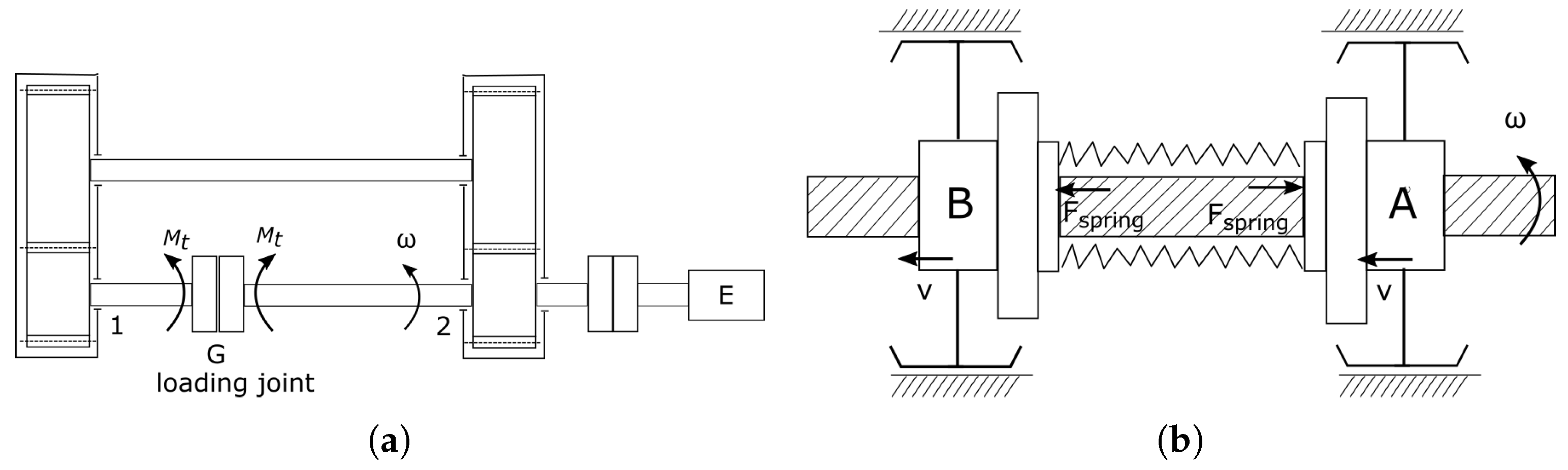
Figure 1a shows the concept of such a device in gear applications: two identical pairs of gears, labelled 1 and 2, are fixed at the end of two shafts and loaded by generating a relative rotation at the joint
G, by means of a predetermined torque. In such a way the gears are preloaded and a twisting moment is applied to all the shafts composing the system. This device is also called “close cycle system”, since during its operation the mechanical work is transferred within the system components, without a significant exchange of power with the outside. As a consequence of the described preload, indeed, the actuation system (i.e., motor
E in the figure) can move shaft number 2 only by introducing the power required to overcome the friction force, while the actual operational loads are transmitted through the gears due to the pre-load.
The same concept is used in the design of the ball screw test rig, substituting the torsional preloads of the gear shafts with an axial preload exerted on the two nuts of a ball screw. A schematic view is reported in
Figure 1b: two nuts, A and B, are mounted on a single screw, and a spring generates an internal force pulling or pushing the nuts one against the other, replicating the “close cycle system” concept. If the rotations of the two nuts are prevented through proper constraints only allowing the longitudinal displacement of the nuts when the screw is rotated (like the sliders represented in the
Figure 1b), the system is in equilibrium under the internal loads exerted by the spring. In such a way, two forces with equal modules and opposite directions act on the two nuts, so that the mechanical power resulting during the screw rotation is nullified. As a consequence, the screw rotation can be actuated by means of a low-power motor, while the nuts can work under the actual operating loads reaching a force of several kNs.
3. Test Bench Design
This section describes the constructive solutions adopted for the development of the experimental test bench.
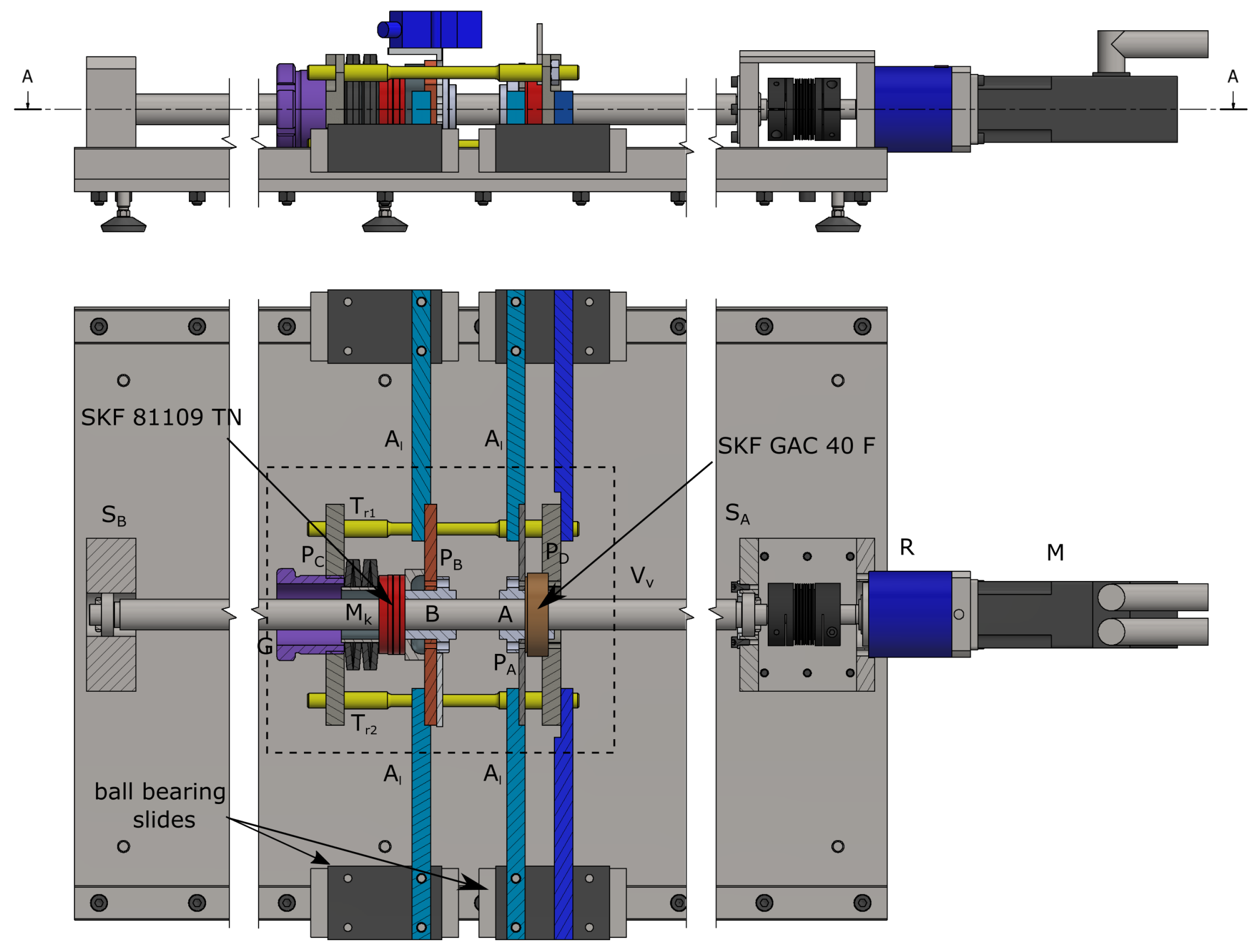
Figure 2 shows top and side views of the whole device.
The system is composed of a mobile group, highlighted in the dashed line square, including the two nuts A and B and the preloading system. The nuts are mounted on the screw , which is supported by two bearings and and actuated by an electric motor M through a reducer R. The rotation of the two nuts is prevented by four lateral aluminum wings , connected to the mobile equipment and to the nuts on one side, and to ball bearing slides on the other side (model HIWIN HG-H-30-CA2R-1160-ZA-HII). This system is capable of blocking the rotation of the nuts and ensuring their translation during the test. The two bearings holding the screw are SKF 6003: the one nearest to the motor (i.e., ) is axially fixed, while the other is free to move in the axial direction.
The two nuts A and B are respectively joined to two steel plates and , which are fixed at their extremities to the four lateral wings . The spring generating the preload on the two nuts is labelled as in the figure. It is placed outside of the screw section included by the two nuts, so as to allow the installation of the loading system without the need of disassembling the ball screw. A belleville spring is selected to generate the load, due to its capacity to exert a high force with a small compression.
The spring load is transmitted to the nut in the following way: on the right hand side, the spring transmits the force to the
plate through an axial tapered roller bearing (SKF 81109 TN). On the left hand side of the figure, the spring transmits its force to the plate
, and then to the plate
through the four beams
(axisymmetric, so that only
and
are visible in the figure). The load is then transmitted to the plate
through an orientable bearing (SKF GAC 40 F), and finally to the nut
A. In this way, the two nuts are pushed against each other, and the screw portion between them is axially compressed. The axial load on the two nuts can be adjusted by changing the spring deflection, which is obtained by screwing or unscrewing the ring nut indicated with
G in
Figure 2.
The combination of the axial bearing (close to the nut
B) and the orientable bearing (close to the nut
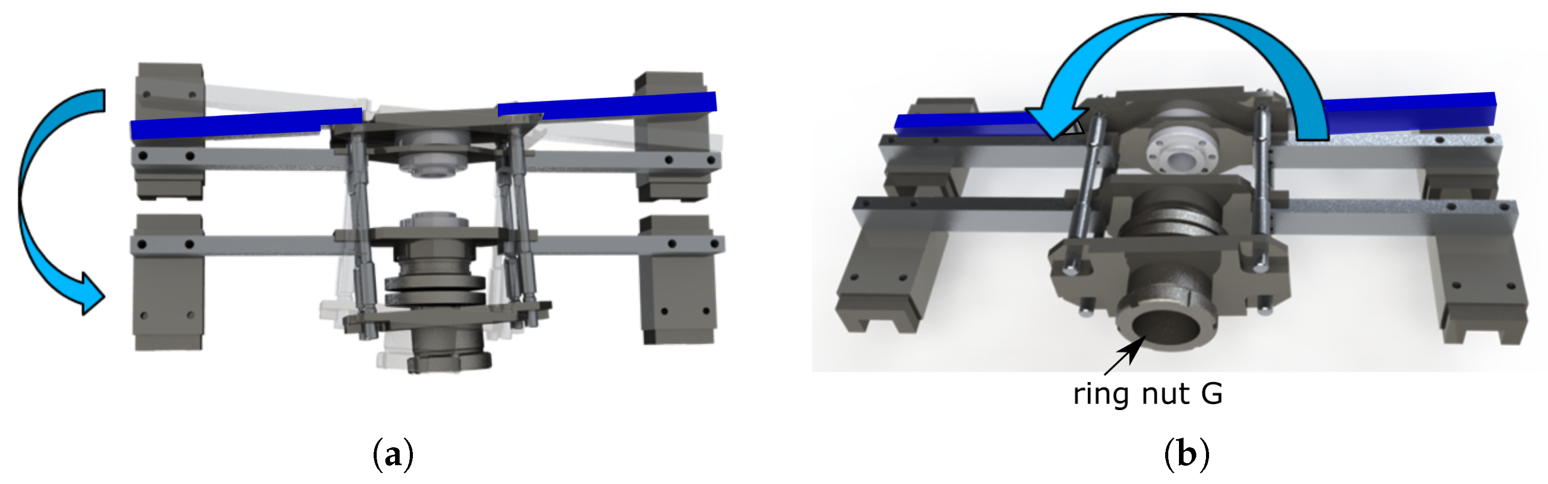
A) is designed to make the axial load the only component acting on the screw. The system generating the load is indeed able to auto-align with respect to the two nuts, and flexural loads are prevented. The two schemes in
Figure 3 exemplify in an emphasized view the function of this autoaligning system. The rotations allowed to the moving equipment (light blue arrows in
Figure 3a,b) prevent respectively the transmission of flexural loads and of torsional loads to both the nut and the screw. The two blue wings at the back (represented by the same colour as in
Figure 2 for the sake of clarity) allow to counteract the torque exerted on the ring nut G when preloading the spring.
A properly sized motor-reducer group actuates the screw by using a torsionally rigid coupling. A low power is required by the motor due to the fact that the preload force is confined in a closed subsystem, including the two nuts and a screw section between them: the loading spring generates two contrasting internal forces on the two nuts, so that when the screw rotates, the net mechanical work needed to move the loaded nuts is null. This expedient allows to reduce the total mechanical power required to move the mobile equipment to merely inertial and friction forces like those occurring in the screw–nut contact and bearings. Note that the latter are usually negligible when compared to the mechanical power required in the traditional layout for ball screw testing, where a single nut is loaded with an external force. As a consequence, the proposed solution allows to simplify the design of the test rig; the bearings used for the screw and the side sliders do not bear high forces even if the nuts are preloaded with a high force.
4. Mathematical Model
In the design phase of the test rig, a mathematical model is developed and adopted to evaluate the torque required by the motor and the reaction forces on the ball-bearing slides of the anti-spin system. The mathematical model aims to be as simple as possible, but sufficiently accurate to ensure the proper sizing of the test bench and to estimate the forces resulting from the endurance tests. Assuming to neglect the friction force acting on the sliders, one can simplify the required motor torque equations during an endurance test, making the resolution method non-recursive [
18].
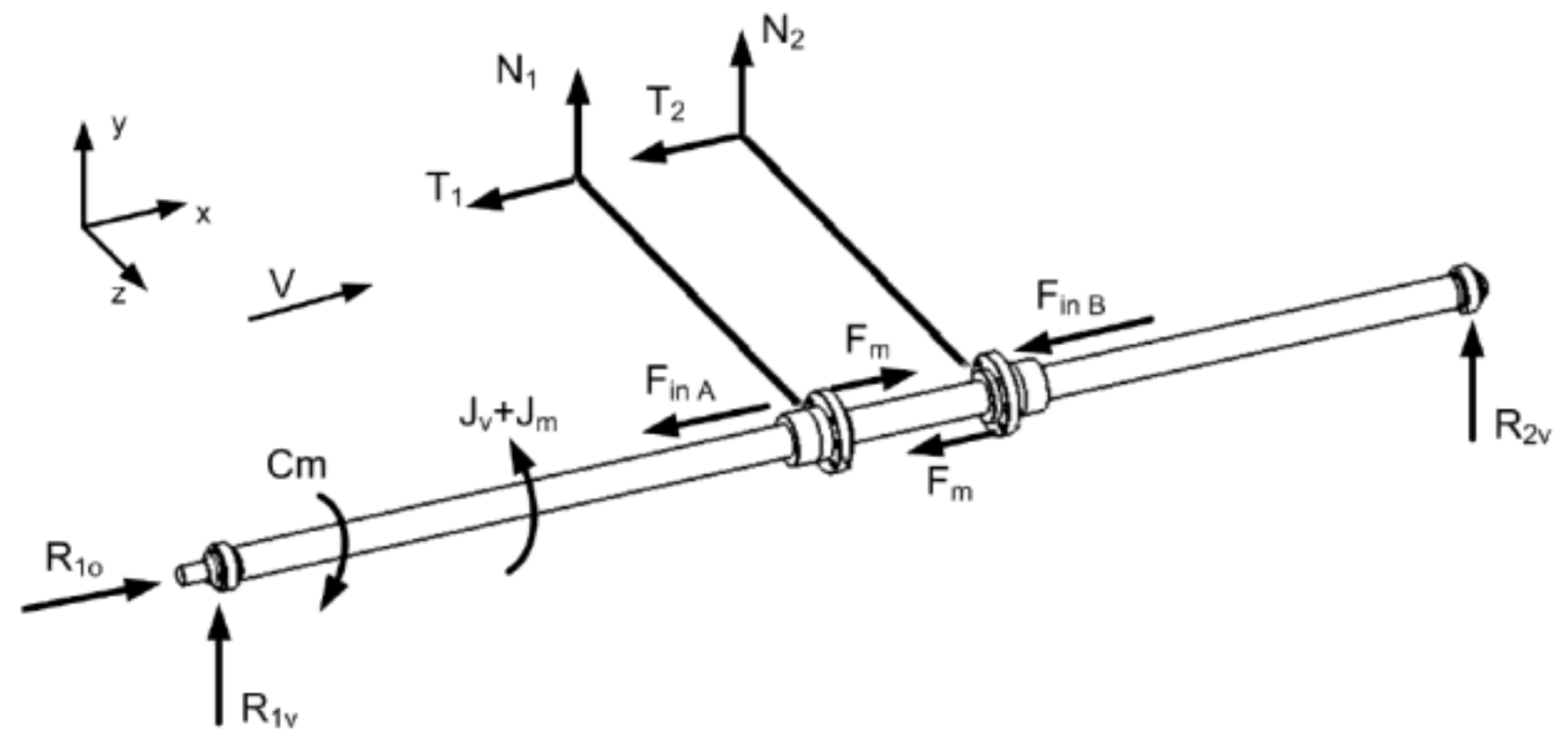
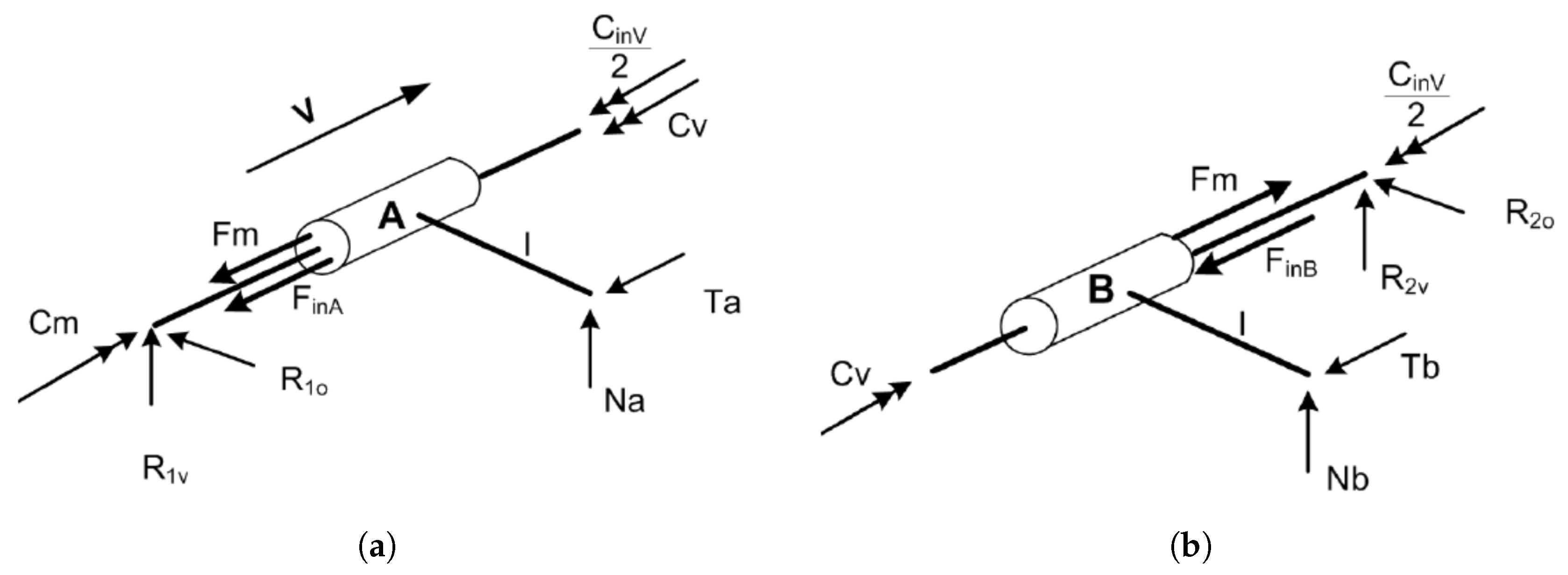
The system under analysis is hyperstatic; every nut is fixed to the ground both through the screw, blocking the translations in all directions except along the screw axis, and by the two tiny wings, preventing the nut spinning around the screw. The geometry of the mechanical system is then simplified with the aim of force analysis; by assuming the symmetry of the loads with respect to the screw axis, it is possible to consider, for each nut, only one of the two wings of the anti-spin system, so as to make this constraint isostatic. The value obtained by force analysis will thus be halved in order to take into account the missing wing. The scheme adopted is represented in
Figure 4.
,
and
are the reaction forces at the bearings,
,
,
,
represent the normal and friction forces at the slider constraints number 1 and 2. The actions to be considered are: the external motor torque
, the internal spring force
, the forces of inertia of the two nuts
,
, and the mass moments of inertia
and
, related to the screw and to the motor respectively. All the other masses not represented in the scheme are adequately distributed among the previously mentioned components in order to maintain their inertial contribution. The weight of the mobile pack does not relevantly affect the efficiency of the screw–nut contact, being almost entirely held by the sliders that prevent the rotation of the nuts, so that weight forces can be neglected.
The power required to the motor is mainly dependent on the mechanical power dissipated by the friction between the nuts and the screw, since friction forces on sliders and bearings are negligible. The motor torque can be therefore evaluated by analyzing the internal contact between the nuts and the screw. Even if several and detailed models have been developped in the literature, the thread–ball contact is not modelled in detail to the aims of this work, but a simplified model is adopted to get a more straigtforward dimensioning of the system; the recirculating ball screw is studied as a normal screw, where the friction force is evaluated on the basis of the efficiency value supplied by the ball screw maker. Under this assumption, the coupling between the screw and nut can be represented by a two-wedge system, each having a single degree of freedom.
Figure 5 represents the equivalent scheme based on the wedges, with all the forces applied. The wedge translating along the
x (horizontal) direction represents the screw, whereas the wedge translating in the
y (vertical) direction represents the nut. In order to have the same geometric characteristics of the screw thread (
p pitch and
diameter), these wedges must be appropriately sized regarding the following relationship
where
is the thread slope.
By introducing the friction coefficient in the contact between the wedges, it is possible to get the transmission efficiency (direct
and indirect
) by means of the following equations:
where
is the friction angle. The screw efficiencies and the thread slant can be obtained from the producer’s datasheet and be used as an input of the numerical model.
A number of factors can affect the above-mentioned values, such as temperature, load and the like. Friction coefficient
and friction angle
are linked via the equation [
2]:
Experimental tests [
19] and literature [
2] indicate that the friction coefficient value is
cm.
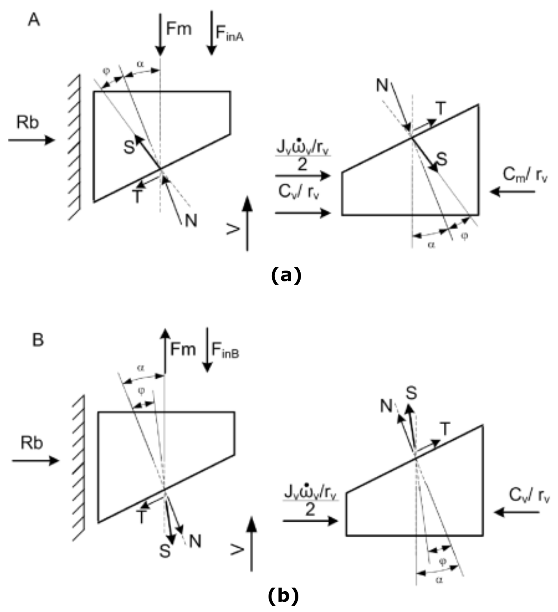
The wedge schemes of
Figure 5a,b represent the two parts into which the screw is divided, each one including one of the two nuts. The former (
A) represents the screw section and the nut close to the motor, whereas the latter (
B) represents the driven part of the screw.
With reference to subsystem
A (
Figure 5a), the wedge on the right-hand side represents the screw, whereas the wedge on the left-hand side represents the nut. In the wedge representation, the motor torque
applied to the screw is reduced to a horizontal force
, where
is the screw radius. The spring force (
), being an internal force for the overall system, is an external force when considering each of the two subsystems
A and
B. Since each nut rotation is prevented by means of the tiny wings, due to the spring force (
) the two nuts tend to rotate the part of the screw between them in opposite directions, generating a torsion moment. In the equivalent scheme based on the wedges this torsion is described as a resistant force, with module
, opposite to the translation of the wedge-screw. The inertia torque related to the entire screw
is divided into equal parts on each of the two subsystems
A and
B, and then reduced to the translational degree of freedom of the wedges; the force
is consequently applied to the wedge representing the screw. The last force acting on the screw wedge of
Figure 5a is the internal force
S exchanged with the nut, sum of a component perpendicular to the contact surface (
N) and a friction component (
T), the latter being opposite to the relative motion between the two wedges. These internal forces are applied equally in magnitude and are opposite in direction on the wedge representing the nut, on the left-hand side of the figure. The other forces applied to this second wedge are the spring force
and the force of inertia
associated to the nut.
The wedge scheme of subsystem
B in
Figure 5b can be interpreted in a similar manner as the previous one in
Figure 5a. The right-hand side wedge, representing the screw, is subjected to the forces related to the screw torsion
and inertia
. The forces applied to the nut are the force of inertia
and the spring force
, the latter having an opposite direction with respect to sybsystem A. As a consequence of the different direction of the spring force
, also the normal component
N of the contact force
S between the screw and nut has an opposite direction compared to the case of nut
A.
In addition to the contact force
S, the unknown variable of the first subsystem
A are the screw resistant torque
and the torque required by the motor
, whereas the only variable of the second subsystem
B is the resistant moment
. These unknowns are solved in the following
Section 4.1 and
Section 4.2 by imposing the translational equilibrium equations on the wedges.
4.1. Solving Subsystem B
The equilibrium equations on the two wedges of the subsystem B have to be solved first, in order to get the common variable to be used to solve the equations related to the subsystem A. It will thus be possible to evaluate the motor torque required to move the mobile equipment. In this paragraph the variable is obtained as a function of the spring force applied on the two nuts.
The following Equations (3) and (4) represent the equilibrium equation on the wedge corresponding to the screw and on the wedge corresponding to the nut respectively.
From Equation (
3), writing the force
S into its two components
N and
T, we obtain:
and from the Equation (
4):
As known, the friction component
T can be written as a function of the normal component
N and of the friction coefficient
(or friction angle)
, as follows:
It is then possible to rewrite Equations (
5) and (
6):
The system is finally solved by calculating
N from the second equation of Equation (
8), and getting, from the first equation, the value of
as a function of the spring force
acting on the two nuts:
4.2. Solving Subsystem A
Once that the value of
is obtained as a function of the spring force
, the equilibrium of subsystem
A can be solved, to evaluate the torque
(make reference to
Figure 5a). Having ascertained that the equilibrium equations are similar to the ones pertaining to subsystem
B, one can consequently assert the following:
Writing the contact force
S as the sum of its components
N e
T it is possible to obtain, from Equation (
11):
and from the Equation (
12):
Substituting Equation (
7) into Equations (
13) and (
14), we obtain:
The solution of system Equation (
15) is obtained by substituting the value
, previosly calculated in Equation (
10), into the first equation, and getting the value of
N from the second equation. The variable
is then written as follows as a function of the spring force
:
In addition to the motor torque, the mathematical model allows evaluating the normal reaction at the slider, namely for subsystem A and for subsystem B.
With reference to the schemes of
Figure 6, and taking into account the wing belonging to the subsystem
A (
Figure 6a), the reaction force
depends on the ratio between the torque applied on the nut
A and the wing length
l:
This result must be halved to take into account the fact that there are two wings. Now taking into account the wing belonging to the subsystem
B (
Figure 6b), the reaction force
depends on the ratio between the torque
and the wing length
l:
It is noteworthy that the reaction forces and are different as regards both magnitude and direction. This is due to the spring action that pushes the two nuts in opposing directions, and thus seeks to rotate such screws in two contrasting directions.
4.3. Change of Direction of the Screw Rotation
The calculation procedure set out above is expressed by taking into account a precise direction of movement of the mobile equipment indicated by the velocity vector
V in
Figure 6.
Inverting the direction will result in a different orientation of the friction forces, always being opposite to the direction of the velocity, and consequently a different behaviour of the system. By revisiting the mathematical steps presented in
Section 4.1 and
Section 4.2 one can obtain the equations necessary to calculate the motor torque and the value of constraint reactions at the sliders under such working conditions.
5. Experimental Setup
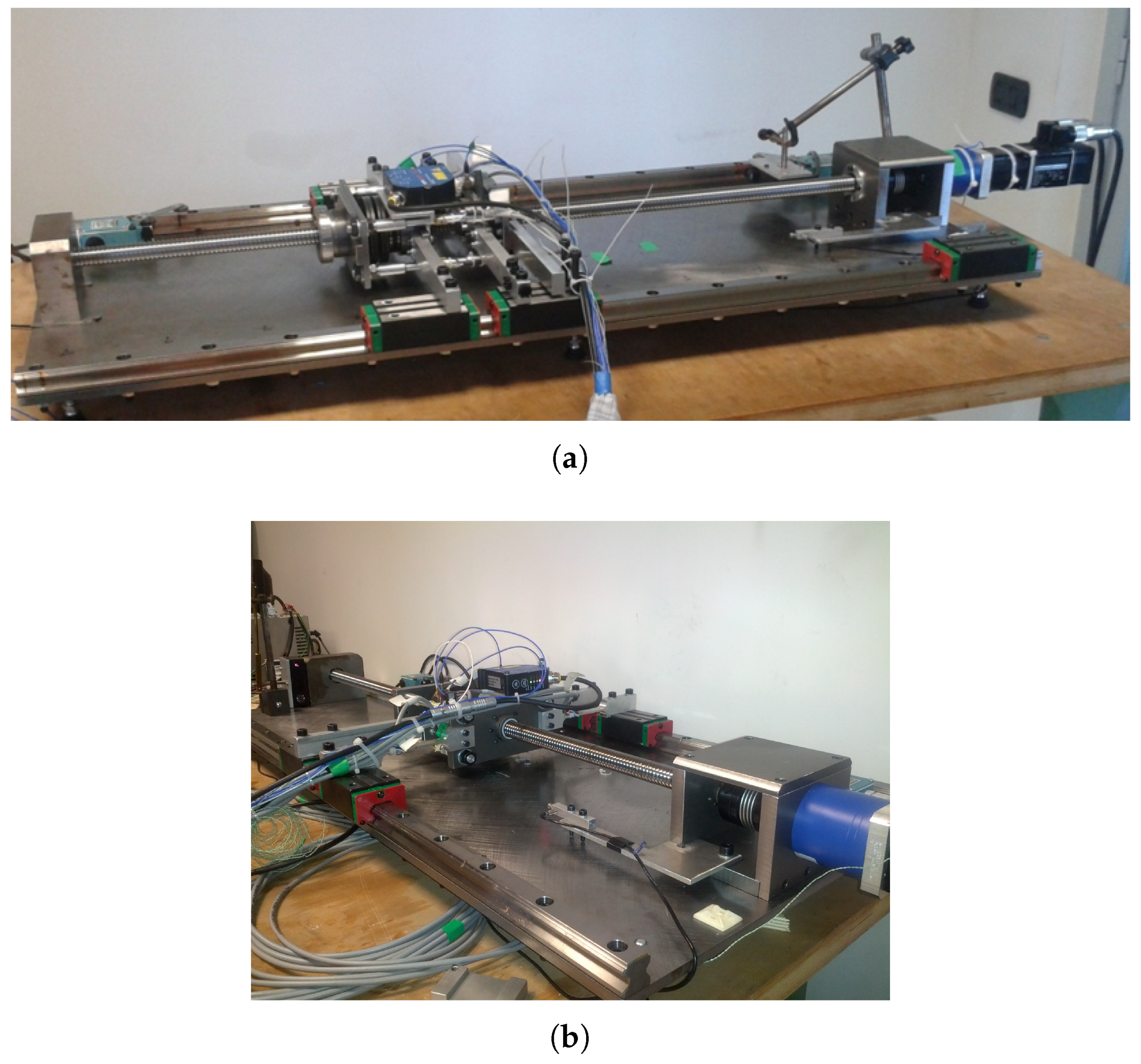
A prototype of the designed test bench is built to verify the applicability of the recirculating power system. In this work, a 25-mm diameter ball screw is used in the prototyping phase for design convenience, even if the peculiarities of the described layout make it particularly suitable for endurance tests of large size ball screws.
The test bench developed is used here for endurance tests. The same approach exploiting recirculating power can nevertheless be used to build a machine for the evaluation of the efficiency of a ball screw under real load conditions, since in the proposed design dissipation is negligible in the auxiliary devices such as bearings and sliders, and the main dissipation terms are located in the contact between the nut and the screw.
The test bench built replicates the design described in
Figure 2. It is equipped with several sensors in order to monitor the behaviour of the system and to identify, as a secondary outcome, the best parameter to be adopted for condition monitoring of the ball-screw during the endurance tests.
Figure 7 shows the prototype test bench.
5.1. Motor Reducer Sizing
As a rule, the choice of the reducer and of the motor is done at the same time.
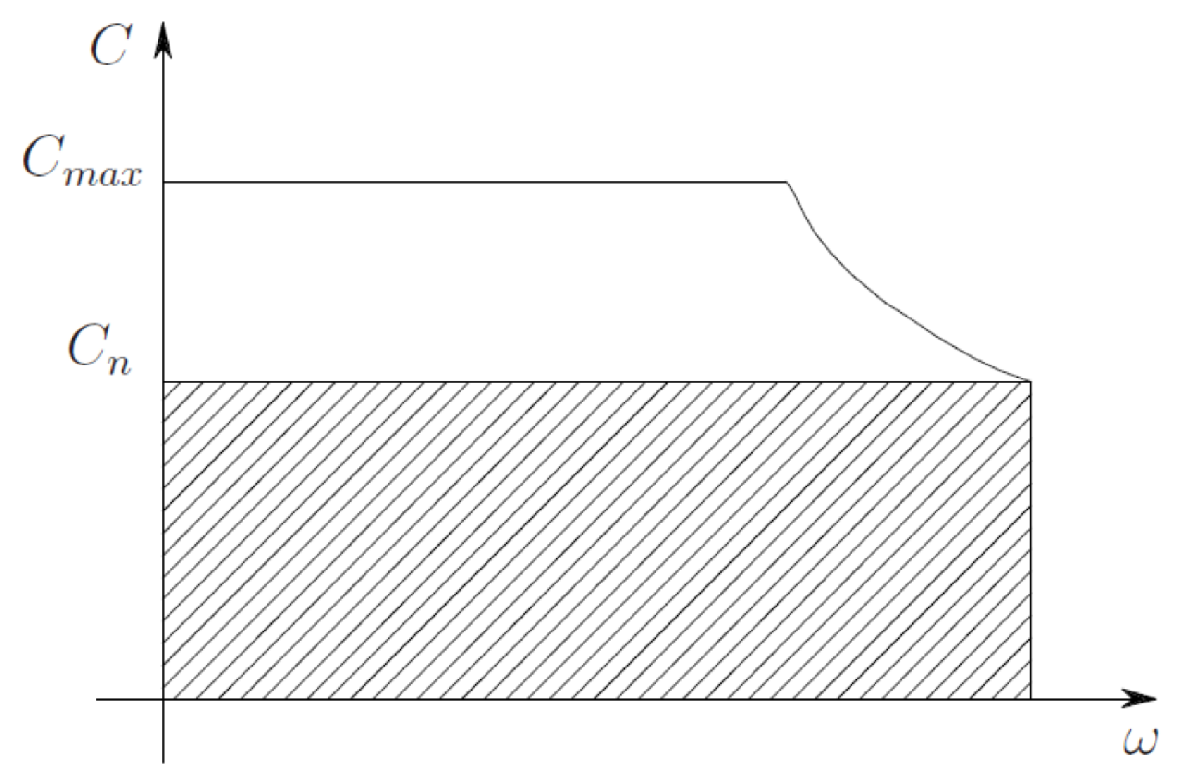
Figure 8 indicates the torque–speed curve of a brushless motor. The nominal torque
is the upper limit of the so-called continuum operation area whereas
constitutes the upper limit of the short term operation area.
The torque
is normally constant to the maximum velocity (
). On the other hand
begins decreasing with effect from the velocity
. As is well known the thermal issues determine the values of the nominal torque
. Assuming that the power dissipated by the actuator transforms into heat proportionately to the square of motor torque
, in order to obtain the correct sizing, one must calculate the root mean square of the motor torque
as follows:
be lesser or the same as the value of
. In order to obtain a correct sizing of the motor the following requirements should be taken into account:
as well as
which must be less than the motor thermal constant
. The following conditions need to be checked simultaneously:
Maximum torque limit:
Root mean square torque limit:
Maximum velocity limit:
Taking into account the relationship
where
is the transmission ratio between motor and load, we consider the movement equation related to the screw axis:
Equations (
20) can be modified as follows:
where
is the load required by the user unit and for our purpose expressed by Equation (
16). The root means square torque required by the motor taking into account the motor rotor inertia and the reducer transmission ratio is obtained by:
Motor nominal torque
has to respect the equation
in order to be able to move the load with the chosen motion law, in other words:
The solution to this problem is amply described in [
20,
21] and summarised as follows. The methodology used is based on the definition of two quantities, the motor
accelerating factor:
that characterises the motor performance and the
load factor:
that characterises the requirements of the user unit. Both factors are expressed in Equation (
W/s). Introducing
and
, in Equation (
23) we obtain:
The
value that minimises the accelerating factor
, making it equal to the load factor
, is the one that nullifies the term within the square bracket, and it is:
Having classified the motors by the accelerating factor
, and defined the transmission ratio limit
, we must choose the one which shows a
value greater than
factor. This value is always known because it depends only on the load requirements. If
the only transmission ratio available is
. Otherwise if
there exists a range of usable
, included between
and
. These values are obtained from the Equation (
26), resolved with respect to
:
If
it is necessary to choose a motor with an
factor greater; if
we must use a reducer with
while only if
the choice of
can be done in the whole range
. Having sized the transmission ratio we can verify the pick torque, in order to ensure that the during the test it will always be:
Note that by using this procedure one can size the motor reducer group taking into account not only the characteristics of the mechanical system (the ball screw used) but also the motion curve for the endurance test. The latter determines the duration of the test.
5.2. Test Bench Instrumentation
The sensors adopted are listed in the following:
A laser positioning sensor MEL M7L/200 is used to measure the absolute position of the translating group.
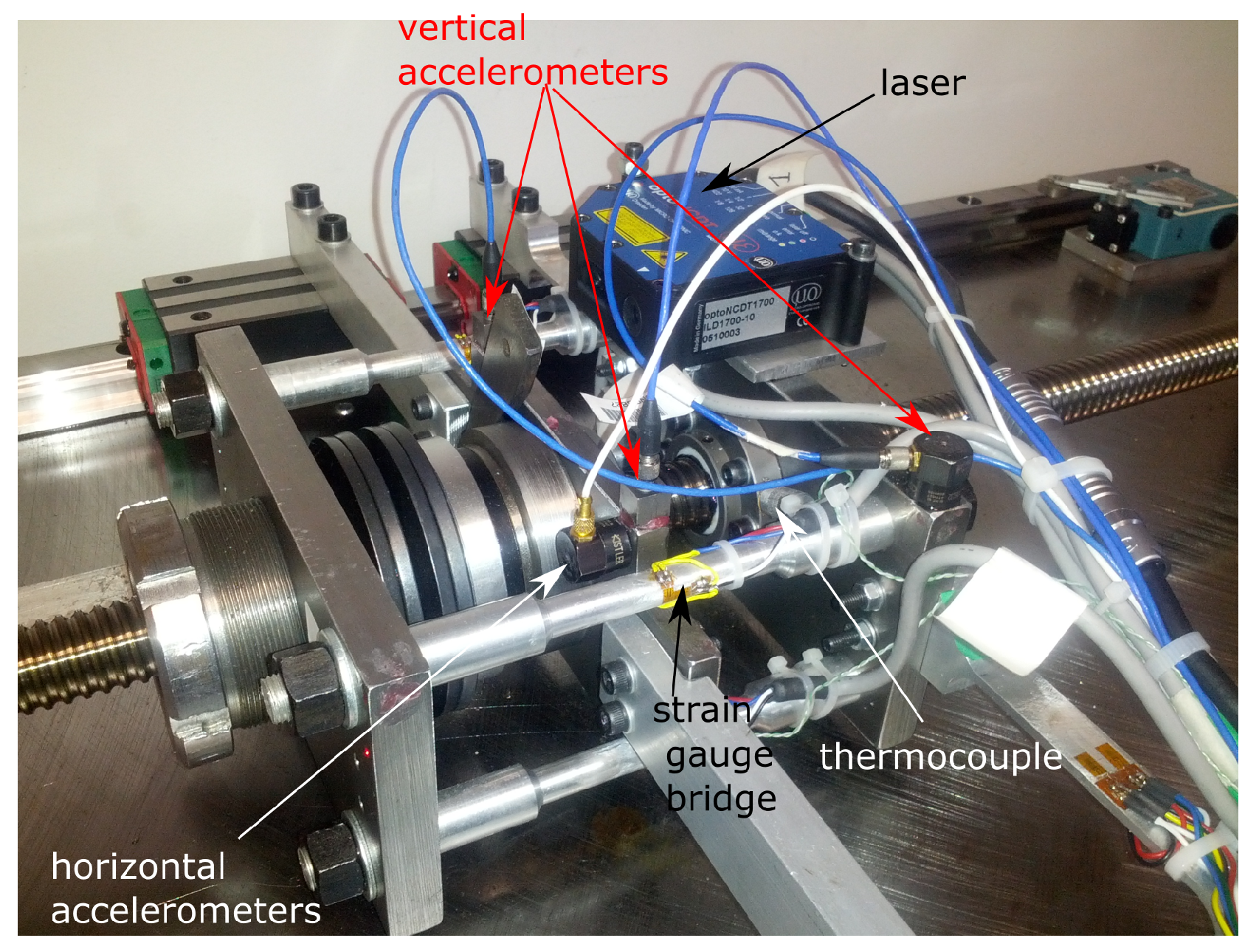
A laser positioning sensor opto NCDT ILD 1700-10 is placed on the translating group (see
Figure 9), to measure the distance between the two nuts during the operating cycle. This measure, which should remain constant during normal operation of the test bench, might be altered due to wear in the screw–nut coupling.
Four full strain gauge bridges are placed respectively on the four beams
,
,
,
, to measure the force applied to the nuts. The sum of the forces measured on each beam is equal to the total force exerted by the belleville spring on the nuts. An exemplary beam with a strain gauge bridge is visible in
Figure 9. Before being installed on the test bench, each of the four beams is calibrated by using an universal testing machine.
Four mono-axial, piezoelectric accelerometers Bruel & Kjaer Deltatron, Type 4508 are used to measure vibrations and to monitor the behavior of each nut during the endurance test. The accelerometers are placed on each nuts in the following way: one with the sensing axis oriented in direction of translation of the nuts (i.e., horizontal accelerometer in
Figure 9), and the other in the vertical direction. The monitoring of the vibrations of the nut is adopted as an indicator of its behaviour during the endurance test, capable of detecting any occurring damage.
Four thermocouples are adopted to measure respectively the temperatures of the two nuts, of the motor and of the environment. The temperature in the nut is an indicator of a potential damage which may occur during the endurance test, leading to an increase of friction forces and consequently to an increase of the heat produced at the contact between the nut and the screw. Thermocouples type K (Cr-Al) are inserted into the nut through its lubrication hole (see
Figure 9). The measure of the motor temperature is exploited as an indirect indicator to detect a possible increase of the torque required to move the mobile equipment, following the increase of friction resistance in the nut-screw coupling. The temperature of the test environment, which should be kept constant during the tests, is finally needed to exclude variations of the system behavior due to experimental boundary conditions.
Three current sensors (ACS712 Allegro MicroSystems sensors), are adopted to evaluate the motor torque.
A proximity sensor is used in the homing procedure.
Simulated encoder: the driver CD1-a-230/10.5 Infranor used to feed the Mavilor motor BLS-55 simulates a 512 points per turn incremental encoder used by the control algorithm in order to close the positioning loop.
The control and acquisition system is based on the NI CompactRIO architecture, combined with a series of C modules capable of conditioning and amplifying different measurement signals. The hardware chosen ensures both software and hardware flexibility, allowing the realization of a control and monitoring system capable of working with large quantities of information and for a lengthy period of time. In detail, the NI CompactRIO 9074 device adopted is equipped with an industrial real-time 400 MHz processor, a data-logging system and an FPGA chassis with 8 slots [
22]. The series C modules the CompactRIO works with are listed in the following:
NI 9205 V, 250 kS/s, 16 Bit, 32-Channel C Series Voltage Input Module for the acquisition of motor current, positioning lasers and proximity.
NI 9401 I/O digital module with 8 high velocity channels (100 ns) to acquire the encoder signals.
NI 9263 Output analog module, V; 4 channels (100 kS/s), 16 bit resolution used to command the motor.
NI 9211 4-Channel, 14 S/s Aggregate, mV C Series Temperature Input Module, for the acquisition of the thermocouples.
NI 9237 4 AI, mV/V, 24 Bit, 50 kS/s/ch Simultaneous, Bridge Completion, for the strain gauges acquisition.
NI 9234 4 AI, V, 24 Bit, 51.2 kS/s/ch Simultaneous, AC/DC Coupling, IEPE AC Coupling for the accelerometer acquisition.
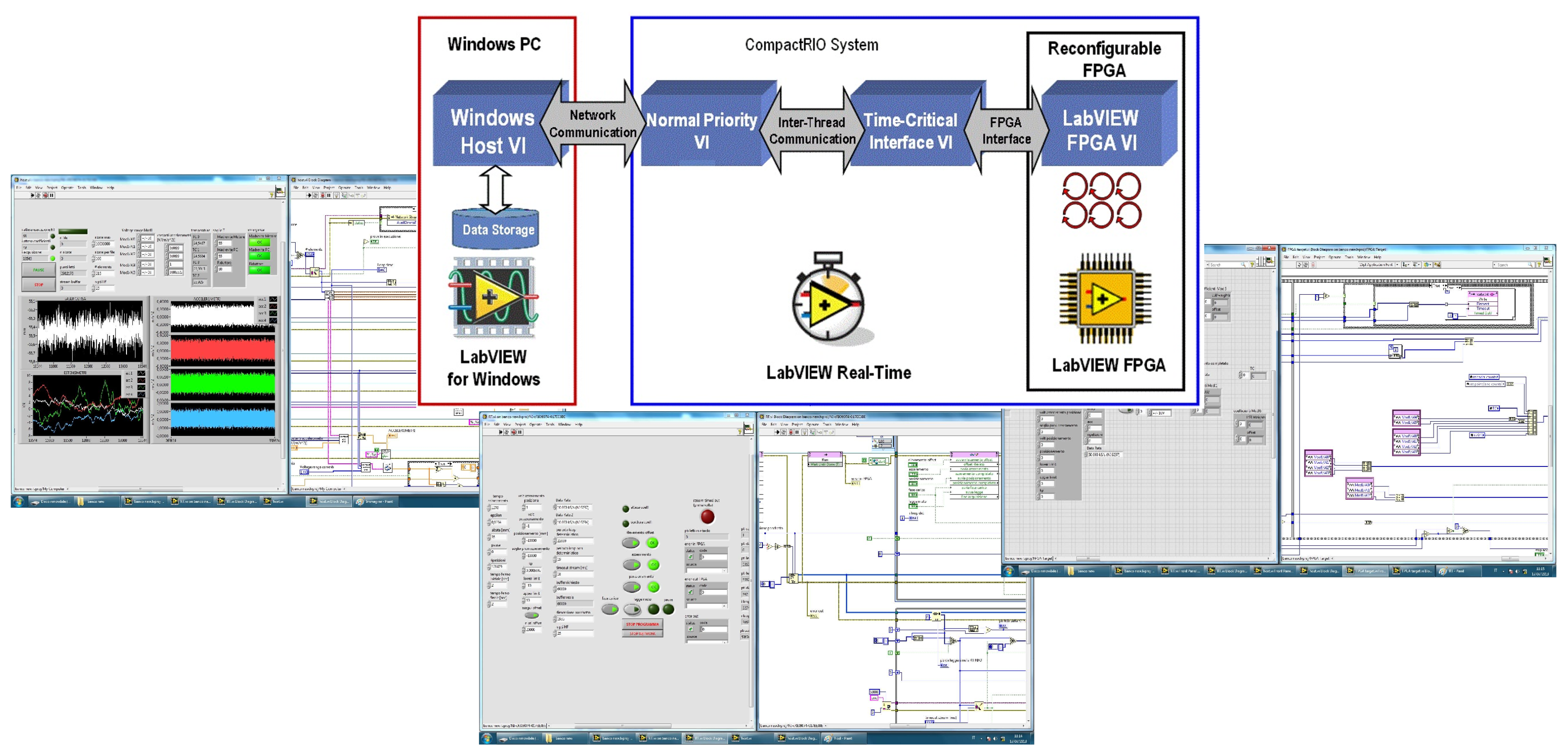
The designed software architecture (shown in
Figure 10) is composed of three VI programs communicating through specific tools. These VIs run on three different target: FPGA VI, Real Time (RT) VI and host VI. The main functions of the FPGA VI are acquiring signals from the sensors by means of the C modules, dispatching them to the real time processor and controlling the movement of the translating group. The RT VI is used to send settings and commands to the FPGA VI, to receive acquired data from the FPGA and to send it to the PC host. Finally, the host VI receives the data from the real-time VI through Network-Streaming, processes the required numerical calculation and logs the data. This architecture allows one to take advantage of the potential of the CompactRIO and, at the same time, the flexibility of a Windows PC host to develop functions with a large amount data.
The sampling frequency is 400 Hz for all channels, with the exception of acceleration signals, which are sampled at 10 kHz. All data are saved in separate files containing 100 working cycles each, (i.e.going and return phase of the nut group), so that a large amount of data is stored during every endurance test. These data are analysed, displayed and post processed through dedicated Matlab scripts developed on purpose. The option of storing the data of each cycle was preferred in the validating phase of the test bench, even if in a final diagnostic application the data can be processed in real time and stored only periodically or if a deviation from the general trend is detected.
6. Experimental Tests and Results
The operating effectiveness of the test bench based on the recirculating power principle has been evaluated by testing a screw with diameter equal to 25 mm and dynamic load capacity equal to 10 kN. Experimental tests have been carried out with the purpose of assessing any limits of the test bench solution proposed, and of highlighting the variety of results achievable through this approach. The obtained results can be therefore regarded as exploratory, and they are exploitable to highlight pros and cons of the proposed solution. The experimental endurance tests are executed by screwing and unscrewing the nuts to obtain a displacement of the mobile equipment enabling the movement of all the balls along the recirculation circuit. The test ends when the maximum number of turns is reached or when the ball screw is damaged.
The nominal life of a ball screw is defined as the number of turns it can perform under a predefined load. In particular, in the case of ball screws with backlash between ball nut and screw shaft and under an axial load applied, the screw life is
where
is the constant unidirectional axial load at which one million cycles is reached.
The parameter
is defined as
in which the load
of the i-th movement phase is weighted with the average speed of the phase itself
, and with its duration
. This formula is corrected according to the type of movement required, through empirical coefficients defined by the screw manufacturers. The standard ISO 3408-5 part 5, specifies the calculation schemes for static and dynamic load ratings and operational life, in order to obtain comparable values for the design and use of ball screws.
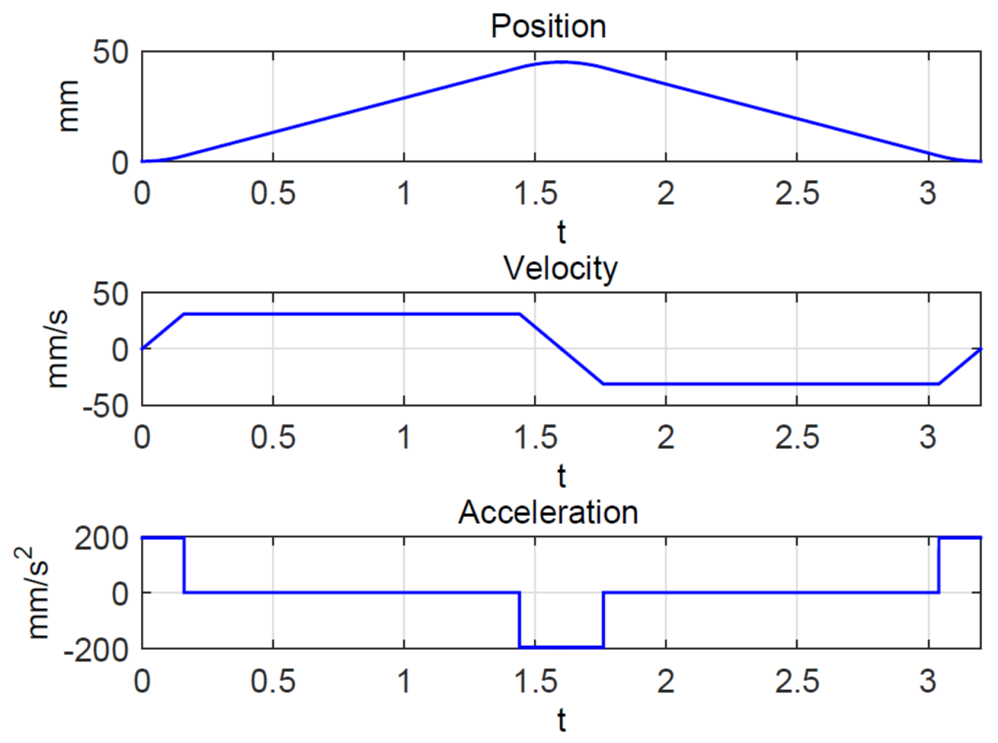
Once that the applied load has been selected, the experimental tests require the definition of the motion law, which is selected as a symmetric law with trapezioidal velocity profile, characterized by the rise value h and the time in which the rise occurs. For the test bench presented, the value of the rise h corresponds to the movement of each nut mounted on the screw. This has to be at least equal to the use length of the nut, but lesser than the distance separating the nuts, so that each nut works on a separate section of the screw. It is, therefore, important to ensure that the distance between the two nuts in the design test bench should be minor than 1.25 times the length of the nut in question.
The time for the rise
is limited by the maximum velocity of the motor, the transmission ratio of the reducer, and the kind of screw. The final motion law selected is characterized by the following parameters: time percentage of acceleration epsilon = 10 %, h = 45 mm total rise, and ta = 1.6 s time to reach the total rise [
19].
Figure 11 represents the motion law used for the tests. This motion law has been selected to have a sufficiently long section with movement at constant speed, so as to better focus on the test bench behaviour during a test.
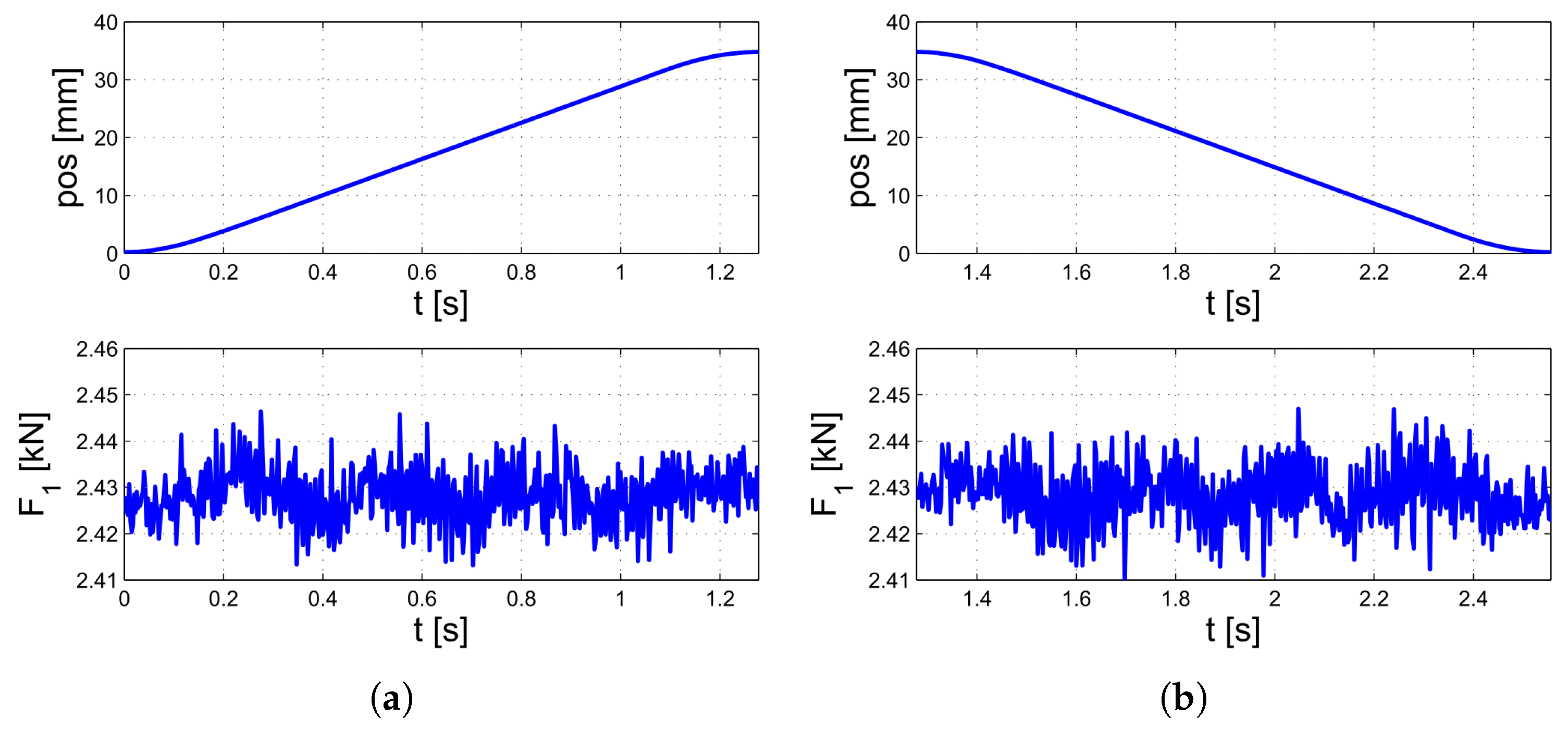
The post processing software analyses every cycle of the mobile equipement for every file saved, dividing each cycle into a go and return phases.
Figure 12 reports an example of the force measured on a single beam
during the going and the return phase, corresponding to an endurance test of a ball screw with diameter equal to 25 mm and pitch 5 mm, with a 10 kN force applied between the two nuts.
For every single go and return phase, the post processing software running on the PC host calculates statistic indicators summarizing the properties of the measurements acquired. The parameters evaluated are:
maximum, minimum and average distance between the two nuts;
maximum, minimum and average values of forces measured by the strain gauges;
maximum and minimum value measured by the thermo-couples;
position of the mobile equipment obtained by the laser;
maximum and average value of the required motor torque;
root mean square value of nut accelerations;
During the endurance tests these values are analysed to identify, in case of a misfunctioning occurring in the ball-screw, which is the most suitable indicator the predict the incipient damage.
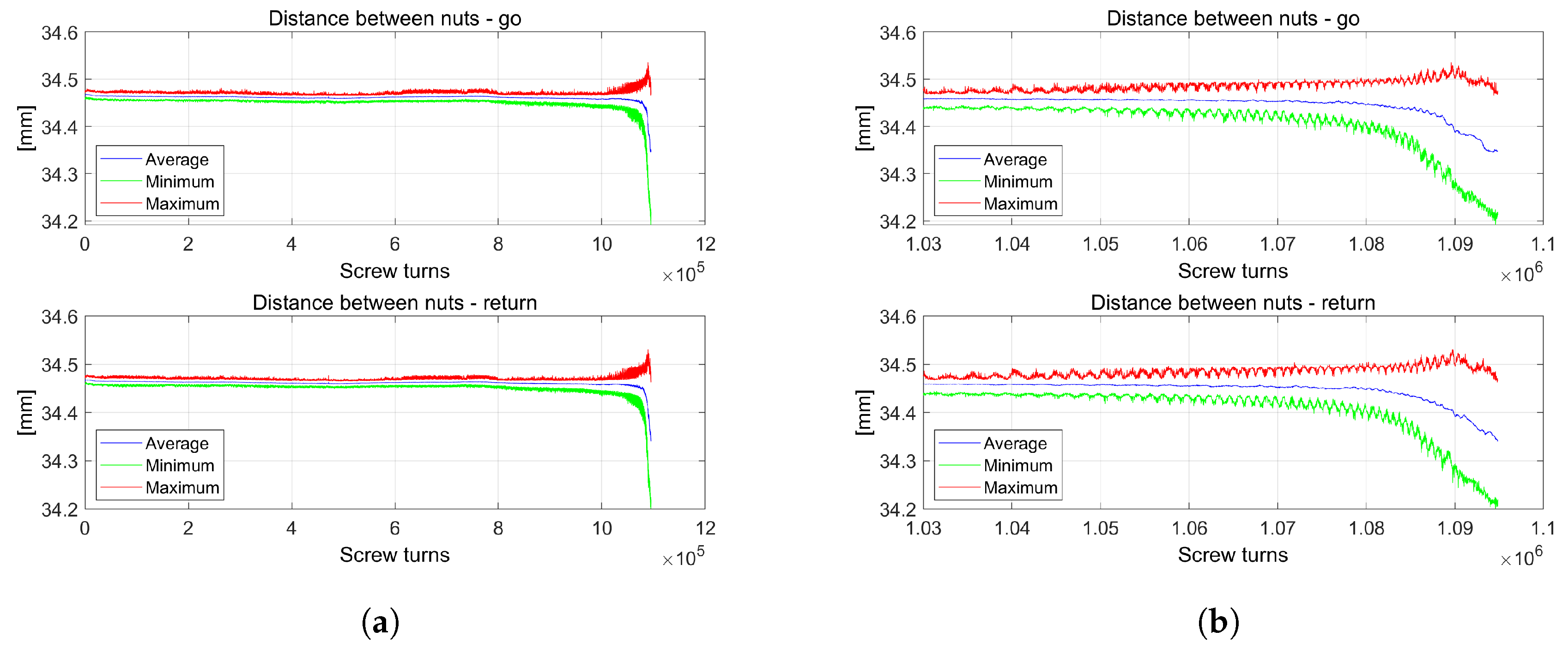
Figure 13 reports the results of the distance between the nuts measured during one of the endurance tests carried out.
Figure 13a shows the maximum, minimum and average distance between the two nuts during the entire test, and
Figure 13b shows an enlargement of the same data corresponding to the final part of the test, when the ball screw begins to wear. Note that the distance between the nuts changes a little bit during the test due to the variation of the environmental temperature (experimental tests have been carried out in a laboratory without air-conditioning, so that daily temperature fluctuations also reached 8 degrees), whereas, during the last part of the test close to
screw turns, this distance starts to change more significantly due to a malfunction of the screw–nut coupling. The distance between the nuts can change indeed in such a significant way only if there is a wear phenomenon or some ball is broken.
The distance variation between the two nuts, due to a change in the ambient temperature, also leads to an unavoidable alteration of the load applied to the screw. When a change occurs in the relative position between the nuts the spring preload is indeed also affected, due to the design of the mobile equipment. The higher the stiffness of the springs used to generate the load, the more amplified is this phenomenon.
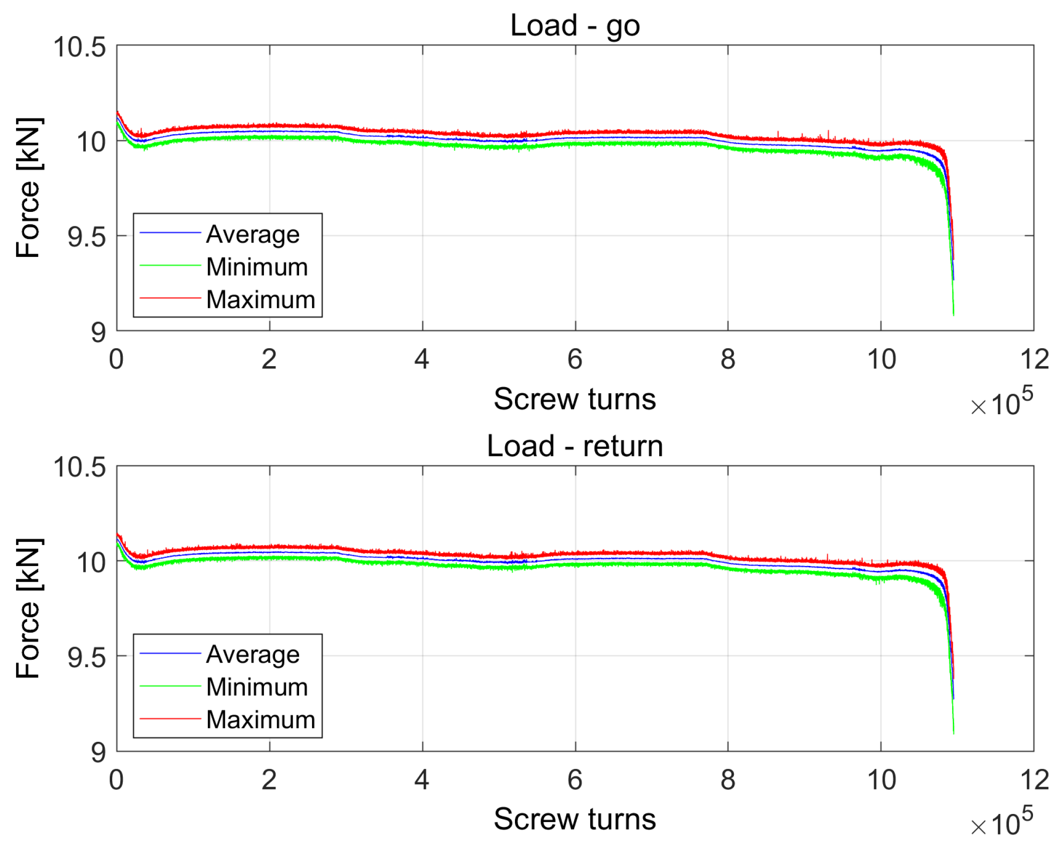
Figure 14 shows the trend of the total load acting on the nuts measured during the same test of
Figure 13. A substantial change is identified at the end of the test, corresponding to the same cycle number at which the distance between the nuts changes in
Figure 13. This happens since the force transmitted by the belleville spring to the nuts is altered due to a variation of the geometry of the system. It should be noted that, when a damage occurs, the loads on the two nuts change more significantly than what happened following the change in the ambient temperature.
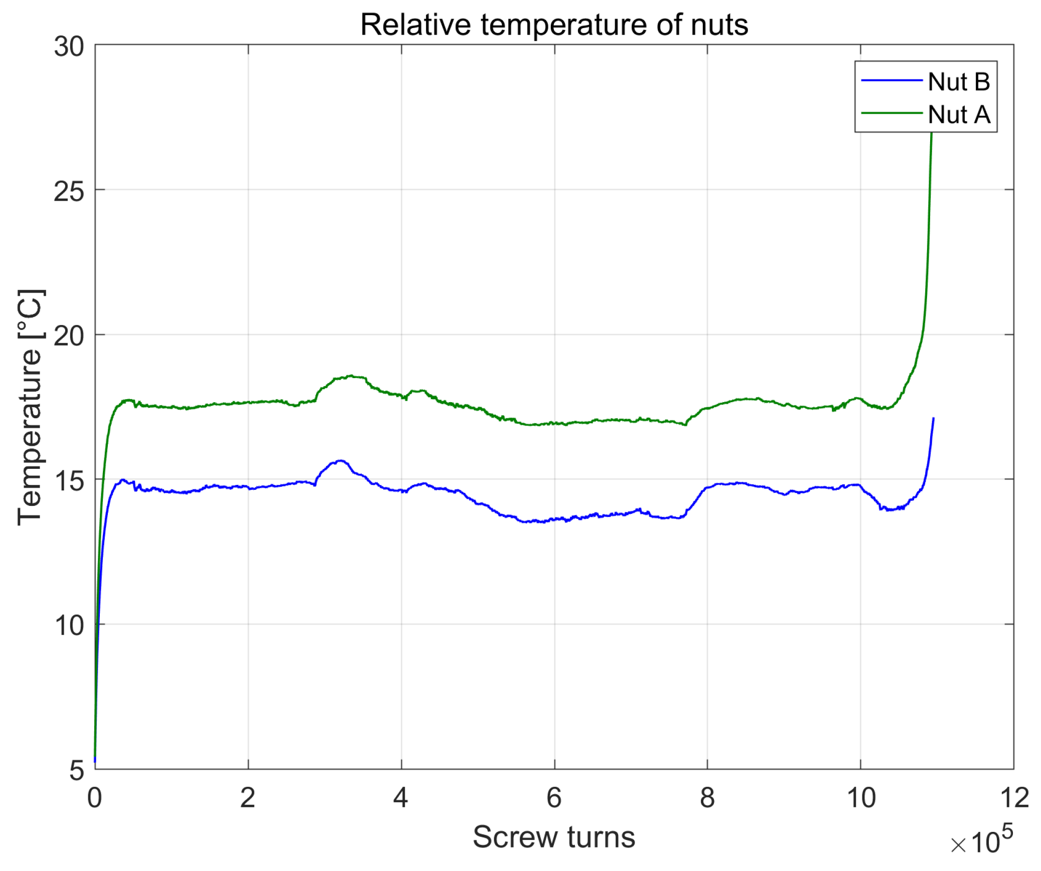
Figure 15 reports, for each of the two nuts
A and
B, the difference between the nut temperature and the environment temperature during the whole test. The temperature behavior confirm the same results obtained analysing the previous signals. Even if two nuts assume slightly different operating temperatures, they keep the same difference throughout the test, until one of the two (i.e., nut A in
Figure 15) is affected by a damage. As a consequence of a decrease in its operational efficiency, the nut temperature starts to rise.
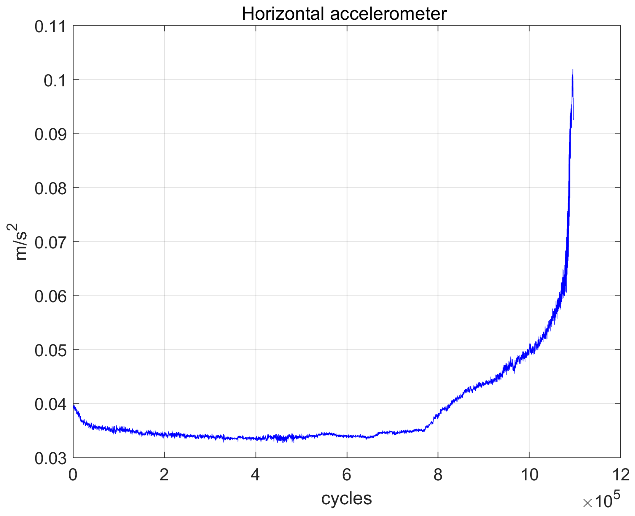
The same trend can be observed in
Figure 16, representing the root means square value of the longitudinal acceleration of the nut
A, evaluated for each cycle during the test. The RMS of the acceleration, close to 0.03 m/s
during the normal behaviour of the system, starts increasing around the cycle number
, and its rate of change keep on increasing until the value close to
, when the macroscopic damage occurs.
By comparing the results of
Figure 16 with those reported in
Figure 13,
Figure 14 and
Figure 15, it is possible to highlight how the RMS of accelerations seems to be the best indicator for damage detection, since its value is able to show not only the presence of a macroscopic damage at the end of the test, but also an increasing trend when the deterioration of the nut begins. Moreover, the acceleration signal is less influenced by temperature, compared to other measures. This result may have a relevant application in ball screw predictive maintenance, since the trend of acceleration is clearly observed to rise at about 80% of its life cycle. However, despite these encouraging results, the change of load acting on the nuts due to temperature oscillation makes the proposed solution less repeatable and precise, so that a further development of the test bench should be carried out before performing a comprehensive analysis to assess the exploitability of acceleration data for screw condition monitoring.
To this regard, a promising solution consists in the adoption of an active load system, capable of compensating for any geometric variations due to thermal deformations.
Figure 17 reports two functional schemes in which hydraulic actuators are adopted to generate the required load on the nuts.
Figure 17a suggests the adoption of two actuators in parallel, whereas
Figure 17b a single bigger actuator connected to the two nuts. In both the solutions, these actuators have to generate extremely limited displacements, in the order of tenths of a millimetre, so that the solution would maintain, from an energetically point of view, the initial economical requirements. The adoption of an actively controlled loading system would also enable the possibility to generate different loading profiles, in agreement to the operating conditions prescribed in the standard ISO 3408. Finally, a repetitive loading system would allow to develop predictive analysis models on the damage, which cannot be reliably performed through a simple and not active system like the one presented in this paper.
7. Conclusions
The paper presented the design and prototyping of an innovative test rig for ball screw testing, based on the power recirculating principle. The concept of using the recirculating principle to realize a test rig for endurance tests on ball screws is promising, not only as concerns the effectiveness of the solution but also for the simple realisation of the system under heavy loads. The test rig is very well suited for use with big size ball screws.
The measure of the distance between the two nuts, the trend of the forces, the root mean square value of the nut acceleration along the movement direction are able to give a complete overview on the screw behaviour and they are useful for monitoring the screw conditon during the entire endurance test. The analysis of the root mean square value of the acceleration along the movement direction of the nut is a simple and useful instrument capable of giving information about the nut and screw condition beforehand, compared to the analysis of the other measured values.
Despite the encouraging results obtained through the recirculating power principle, the change of load acting on the nuts makes the proposed solution less repeatable and precise. One of the main limits of the bench proposed is the lack of a solution to control the load acting on the nuts during the test cycles. This limit can be overcome, as a further step of the work, by introducing an active load system capable of compensating for any geometric variations due to thermal deformations.


