Article

Optimization of the Manufacturing Strategy, Machining Conditions, and Finishing of a Radial Impeller

by
Fotios I. Stratogiannis
,
Nikolaos I. Galanis
,
Nikolaos E. Karkalos
and
Angelos P. Markopoulos
*
Laboratory of Manufacturing Technology, School of Mechanical Engineering, National Technical University of Athens, Heroon Polytechniou 9, 15780 Athens, Greece
*
Author to whom correspondence should be addressed.
Machines 2020, 8(1), 1; https://doi.org/10.3390/machines8010001
Submission received: 21 November 2019 / Revised: 16 December 2019 / Accepted: 24 December 2019 / Published: 27 December 2019
(This article belongs to the Special Issue Advances in CAD/CAM/CAE Technologies)

Abstract

:
Impellers are the most crucial components of pumps, as they directly determine the velocity profile of the fluid flowing through the pump and its efficiency. Given that the impellers have a complex geometry, they pose an important challenge to the manufacturer in order to construct them with the best possible dimensional accuracy and surface quality, and also achieve short machining times. In the present paper, the machining operations for the manufacture of a radial impeller were designed and implemented for the case of a single-entry semi-closed radial flow impeller. At first, the best milling strategies, optimum cutting conditions, and appropriate cutting tools were selected for each of the three machining phases, namely, roughing, semi-finishing, and finishing. Then, an experimental investigation was conducted, especially for the optimum process conditions during finishing of impeller blades, using Taguchi L16 orthogonal array. After the analysis of surface roughness was conducted for the 16 experiments, it was found that the most important parameters were spindle speed and feed. Furthermore, the optimum settings were determined as the maximum spindle speed and the lowest feed per tooth value and a regression model correlating process parameters with surface roughness was established with a high degree of accuracy.

Graphical Abstract

1. Introduction

An impeller is the main rotating component of a centrifugal pump. Usually, it is composed of blades and a hub, with its main function being the transfer of energy from the motor to the working fluid. Impeller blades are composed of a suction surface, a leading edge, and a pressure surface. In the relevant literature, it can be observed that there are more than 120 varieties of impellers [1,2]. The design and manufacturing stages of a pump impeller should comply with three separate, but equally important requirements. At first, the impeller should provide an appropriate relative velocity distribution on both the pressure and suction surfaces of the blade in order to minimize the possibility of flow separation and efficiency reduction. Moreover, the blade shape must be selected in a way that it can be manufactured with adequate precision and with relatively low cost on a computer numerical control (CNC) machine tool. Finally, the blade should be safe regarding its mechanical strength, thus reducing the possibility of excessive deformation or even fracture during its operation [3,4].
Machining of complex 3D geometries has been a topic of interest for several decades as it constitutes a demanding process. Such geometries are usually encountered in the aircraft industry, surgical prostheses, components with optical characteristics, and automotive and electronics industries, among others. In the manufacturing process of complex parts, one of the most important subjects is the tool path patterns, as they determine how the cutting tool processes the surfaces, whether the paths are well-planned, and if efficiency and surface quality can be increased. In the case of impellers, several works have been conducted during the past few decades. Young and Chuang [5] were among the first to investigate the feasibility of machining of impellers on five-axis machine tools in order to overcome common problems arising when machining complex parts on three-axis machine tools, such as possibility of collision and overcut, and at the same time maintain a reasonable machining time. Thus, they designed a detailed algorithm for tool-path generation dividing the machining area into two regions, namely the blades and the hub; they successfully verified the results in simulation software and conducted a detailed analysis of machining error based on comparison with the original geometry as well. Kaino [6] presented various methods for machining of large impellers on five-axis machining centers. He underlined the main difficulties of machining impeller blades such as the constant change of cutting depth and cutting resistance, low machine tool stiffness for rotary axes, and chattering, and proposed using a special technique for the improvement of machining efficiency, adopting contour machining, and employing a tool with variable pitch and lead angle.
The majority of scientific work on impeller manufacturing was concentrated on efficient tool-path generation strategies or optimization of the milling strategies in respect to various indicators. Wu et al. [7] studied the effect of integral impeller stiffness on the machining process in order to determine the optimum machining path. An open impeller was machined in a five-axis vertical machining center and, for the measurements, a single blade was selected. Afterwards, the stiffness matrix of the blade in respect to other parts of the system was created and its performance relevant to the cutter movements was evaluated and validated with experiments in order to determine the optimum feed direction, reduce vibrations, and improve dimensional accuracy. Fan and Xi [8] proposed an adaptive method for the optimization of tool-path during three-axis machining of impeller blades. Their method included the division of the blade surface into four sub-surfaces after their geometry is mathematically defined, and then the tool-paths were generated using an optimization algorithm, also taking in consideration the fluid flow requirements for the impeller. They stated that, using the proposed approach, machining costs can be reduced, tool-path generation is simplified, and geometrical characteristics are in accordance with computational fluid dynamics (CFD) analysis requirements.
Fan et al. [9] developed a novel tool-path generation method for the case of centrifugal impellers with arbitrary surface blades using the flank milling technique. They noted that, although the point machining technique was usually used for arbitrary surfaces, it could be beneficial to combine this technique with features of flank machining in order to increase the accuracy of geometrical characteristics of the blades. Thus, they modeled the arbitrary blade as an approximate ruled blade and applied the flank machining method for rough and semi-finish machining. Finally, they concluded that this approach led to the reduction of machining time by reduction of the path-line length. Li et al. [10] developed a method for smooth machining of ruled-surface blades represented by third-order non-uniform rational basis spline (NURBS) curves. After creating the computer-aided design (CAD) model of the blades, the machining process was programmed and verified in a CNC machine tool. Their findings indicate that the CAD model using NURBS required fewer points than other types of surfaces; the adopted interpolation method led to smoother and more precise trajectories with lower machining error. Fan and Xi [11] presented also a new tool-path generation method for special cases of machining centrifugal impellers. At first, they noticed that the commonly employed isoparametric method for tool-path generation was not sufficient, as it led to an increase in machining time. The proposed method was based on the generation of a new type of machining layers of the final geometry and was able to produce sparser tool-paths with a shorter length, something that simplified the calculation process of the tool path curves and increased the efficiency of the machining process.
Tang et al. [2] presented an interesting study about the tool-path generation during the clean-up stage of the impeller machining process. In order to be able to remove the unwanted material remaining after the finishing process in some regions, they developed a method related to point-searching for determining the appropriate tool paths and implemented it on computer-aided manufacturing (CAM) software to test its feasibility. Their findings showed that the method is efficient in planning the appropriate tool-paths for the clean-up process in a simple way and led to rapid and accurate determination of the clean-up regions. Fan et al. [12] created a novel strategy of five-axis machining of centrifugal impellers based on regional milling for both roughing and finishing stages. Specifically, this approach can combine favorable features of both flank and sub-surface machining methods. For the roughing stage, the objective was to choose a cutter with relatively large diameter and achieve the shortest path length, whereas for the finishing stage, owing to the fluid flow requirements, interlinking of tool path curves in some regions as well as reduction of tool interference should be achieved. Finally, machining efficiency during roughing by reducing the required time and better distribution of machining errors along with increased aerodynamic efficiency during finishing was achieved.
Wang et al. [13] presented a multi-parameter optimization study regarding the manufacturing of an axial impeller in a five-axis machining center. They introduced a cost-effective method for machining parameters optimization based on absolute average error and standard deviation of online measured points using grey relational theory to define a single objective optimization problem with three variables, namely, the length to diameter ratio, depth of cut, and feed rate. Arriaza et al. [14] conducted a study regarding the compromise between machining time and energy consumption during rough machining of impellers. In their work, they conducted an optimization using the response surface methodology with four input variables, namely, spindle speed, feed rate, depth and width of cut, and two responses (consumed energy and machining time). Their findings indicated that the selection of an appropriate feed rate value can lead to reduction of the necessary spindle speed as well as the depth and width of cut; spindle speed was found to be the most important factor for controlling energy consumption and width of cut was the most important factor regarding machining time.
Chaves-Jacob et al. [15] presented a numerical method for the optimization of the finishing process for the five-axis machining of impeller blades. In their work, they focused both on geometric and cost indicators and compared point milling and flank milling strategies using these indicators for the case of an industrial impeller. They proposed that this method can be employed to determine the optimum strategy in other cases of complex workpieces. Peng et al. [16] compared different methods for fabrication of impellers such as conventional manufacturing, additive manufacturing, and remanufacturing, regarding their environmental impact. More specifically, they employed plunge milling, laser cladding forming, and additive remanufacturing techniques, and then a life cycle analysis was conducted for them. It was shown that remanufacturing was the better choice, followed by additive manufacturing and conventional manufacturing. However, the pure additive manufacturing processes can sometimes be less environmentally friendly than the conventional ones, owing to increased power and material consumption.
Young et al. [17] further investigated the roughing strategies for five-axis impeller machining in order to develop a methodology especially suited for the efficient roughing of centrifugal impellers by taking into consideration the appropriate depths of cut required, the residual material thickness and surface conditions on the tool path, and the control of step-over. Tang et al. [18] investigated the effect of the use of a varying feed rate during machining of blades in a four-axis machining center. They noted that the use of constant feed rate on four-axis machining centers results in overcutting near the leading and trailing edges of the blade, and thus they determined the appropriate lead angle and speed of each axis to overcome this problem. By controlling the lead angle, they achieved the avoidance of collisions and, by imposing limitations on the feed speed and acceleration, overcut was also avoided and precision was improved for the produced blade. Heo et al. [19] proposed an efficient method for roughing of impellers in the case of five-axis CNC machine tools. At first, they noticed that, owing to more complex control requirements for five-axis machines, the required time for roughing was increased compared with that for three-axis machines. Thus, they developed a novel method for machining the impeller by dividing it into various unit machining regions, where machining would be performed in a similar way as in three-axis machines using a repetitive procedure. This can be achieved by fixing the rotating and tilting axes of the machine bed and then, by maintaining the cutting tool at a suitable inclination angle in respect to the blade surface, it was ensured that no collision would happen as well. Kim et al. [20] also proposed a method for the machining of impellers by integrating techniques applied to three-axis and five-axis machines in order to reducing roughing time. They noted that five-axis machines require long machining times for producing a single product, although they can avoid collisions more easily than three-axis machines. Their approach involved two distinct steps: a first step of three-axis machining and a final step of full five-axis machining for the completion of the roughing process. The method was applied to both a splitter and non-splitter type impeller and it was shown that, in both cases, the tool-path was shorter and total machining time was reduced by 17% and 11%, respectively.
From the aforementioned studies in the relevant literature, it can be concluded that the majority of works regarding impeller manufacturing have focused on the generation of optimum tool-paths and optimization of process parameters for different machining phases. However, works on manufacturing of radial impellers were somewhat limited, as well as the studies on optimum finishing conditions using high spindle speed values. Thus, in the present work, it is intended to present a detailed study on the manufacturing of a radial pump impeller, beginning with the design of required machining operations, their actual implementation, and the evaluation of surface quality of the radial impeller after conducting an investigation regarding the optimum finishing conditions.

2. Methodology

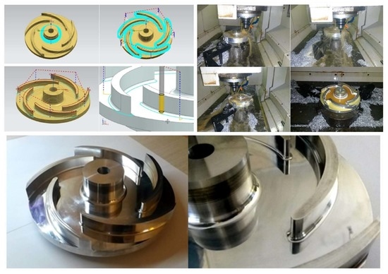
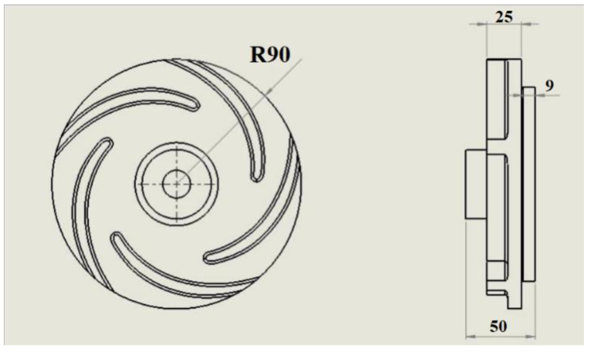
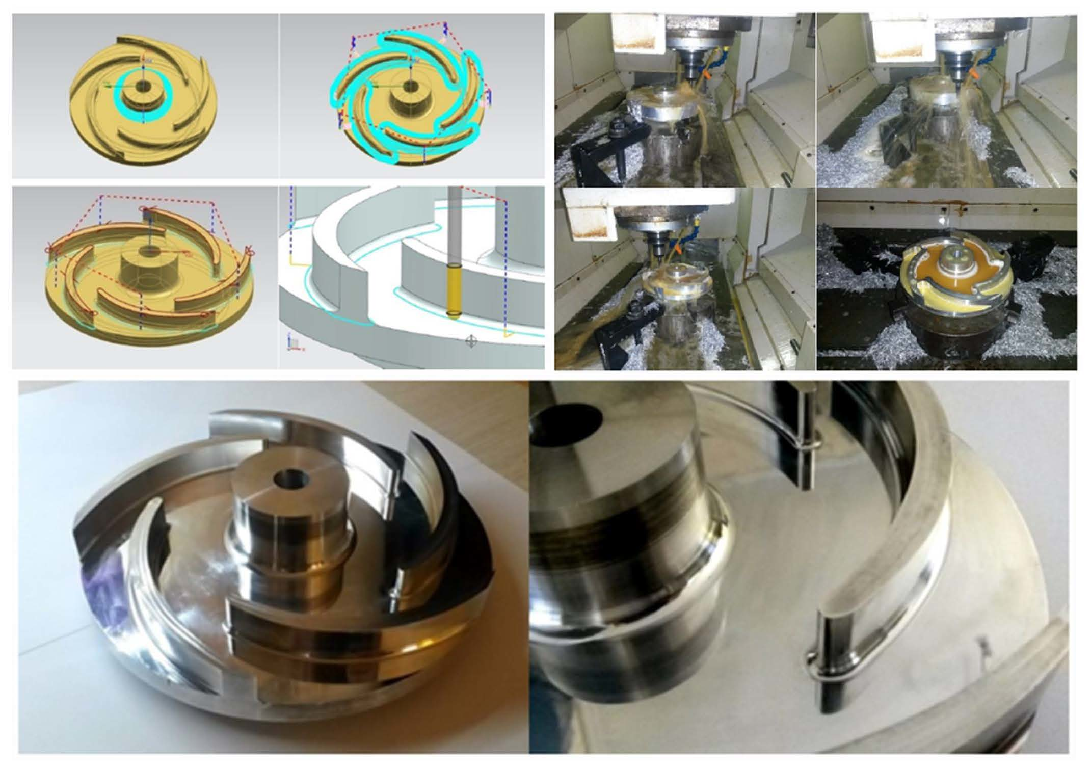
After the initial design of the appropriate geometry of the radial impeller, illustrated in Figure 1, as well as its evaluation regarding its aerodynamic characteristics, which were investigated in a previous study [
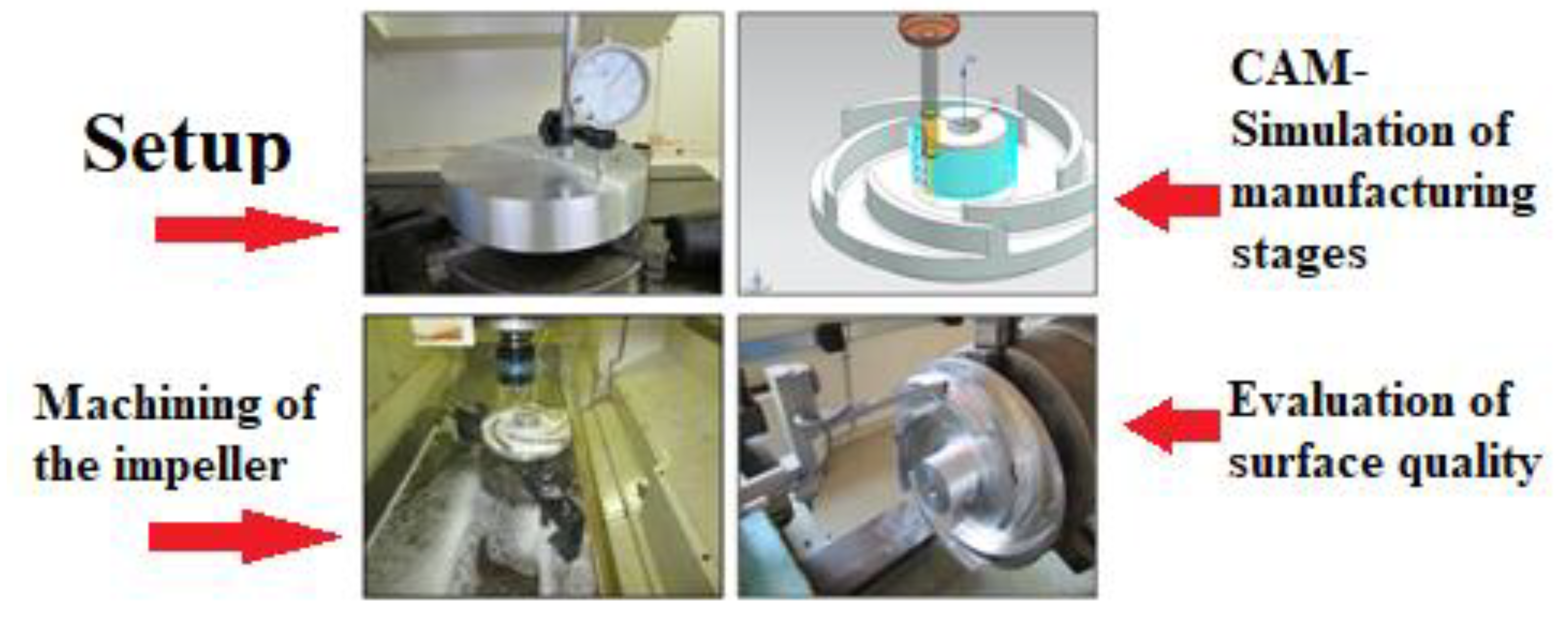
21], the manufacturing of the actual impeller was able to be conducted. The design of the machining process of the radial impeller, which includes complex geometries, is essential to be conducted using specialized CAM software, such as NX CAM, which can be accessed through Siemens NX software. Some of the main challenges regarding the machining of complex geometries of the impeller blades or vanes and hub are the achievement of the required dimensional accuracy and surface quality, as well as the reduction of machining time. Apart from the use of cutting tools with a special geometry, the machining strategy needs to be carefully planned in order to achieve the desired geometrical features and suitable process parameters are required to be determined as well. Thus, all of these tasks need to be appropriately addressed by the use of CAM software in order to successfully perform the machining process of the impeller.
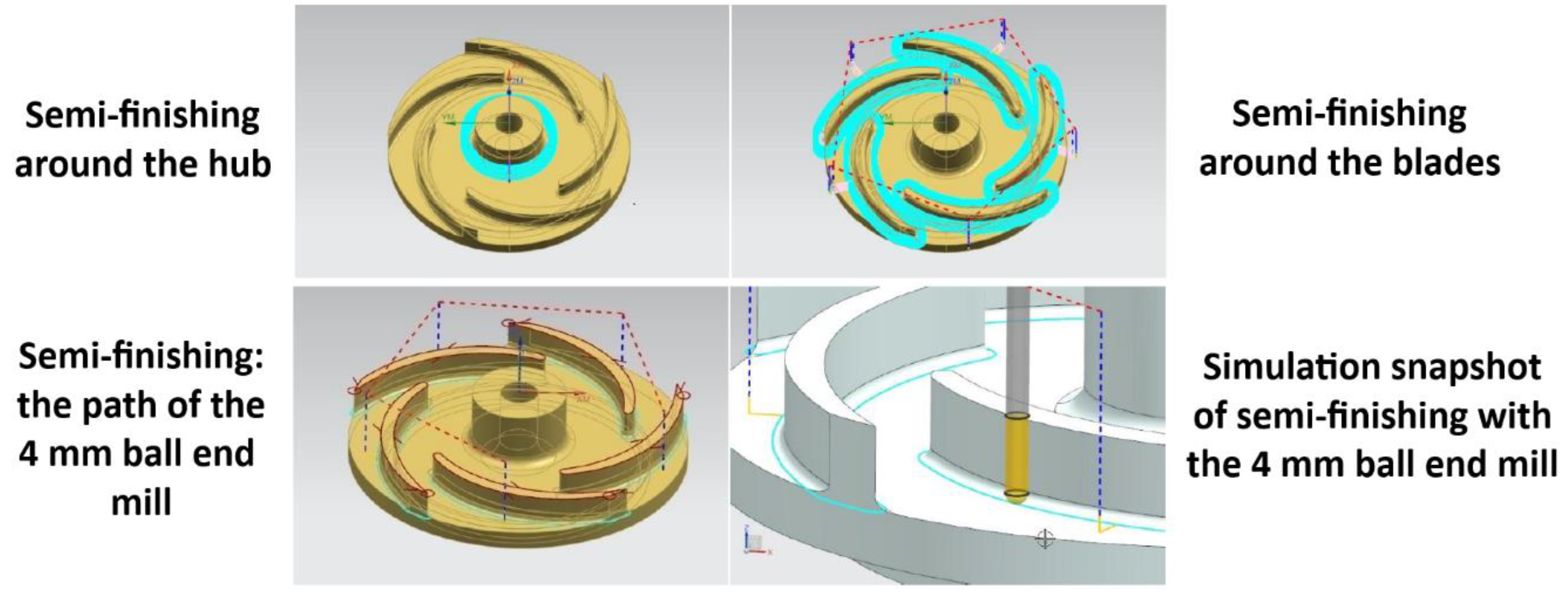
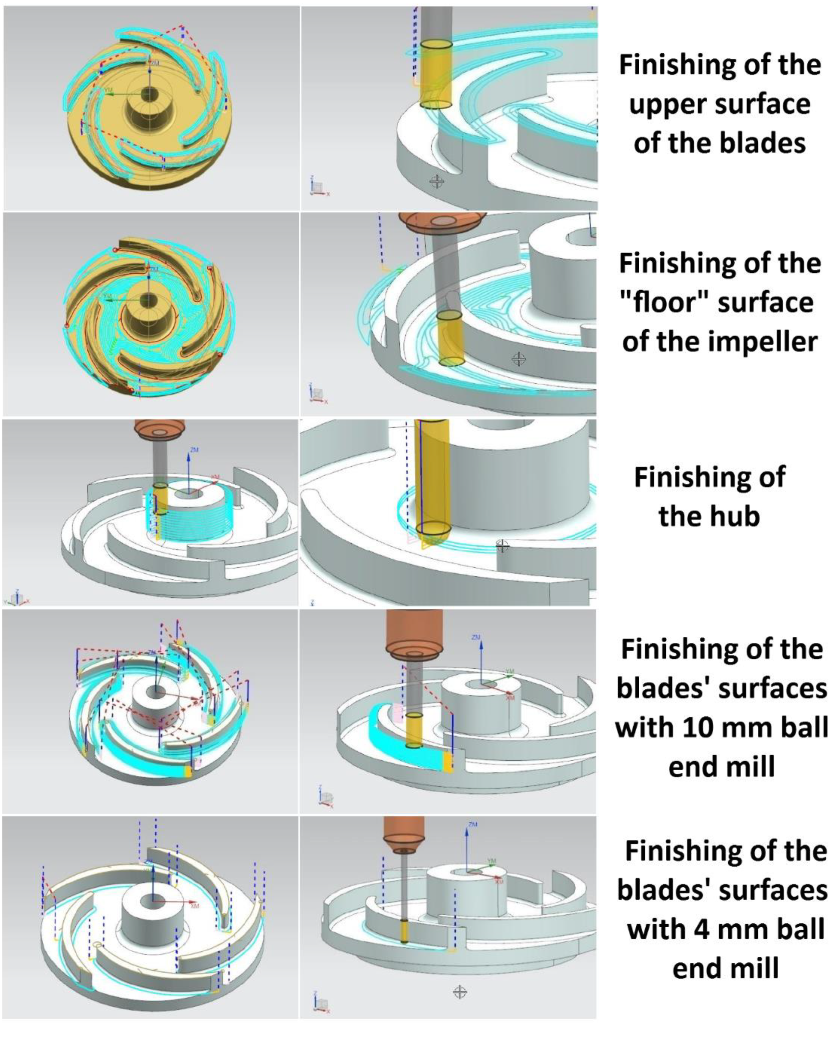
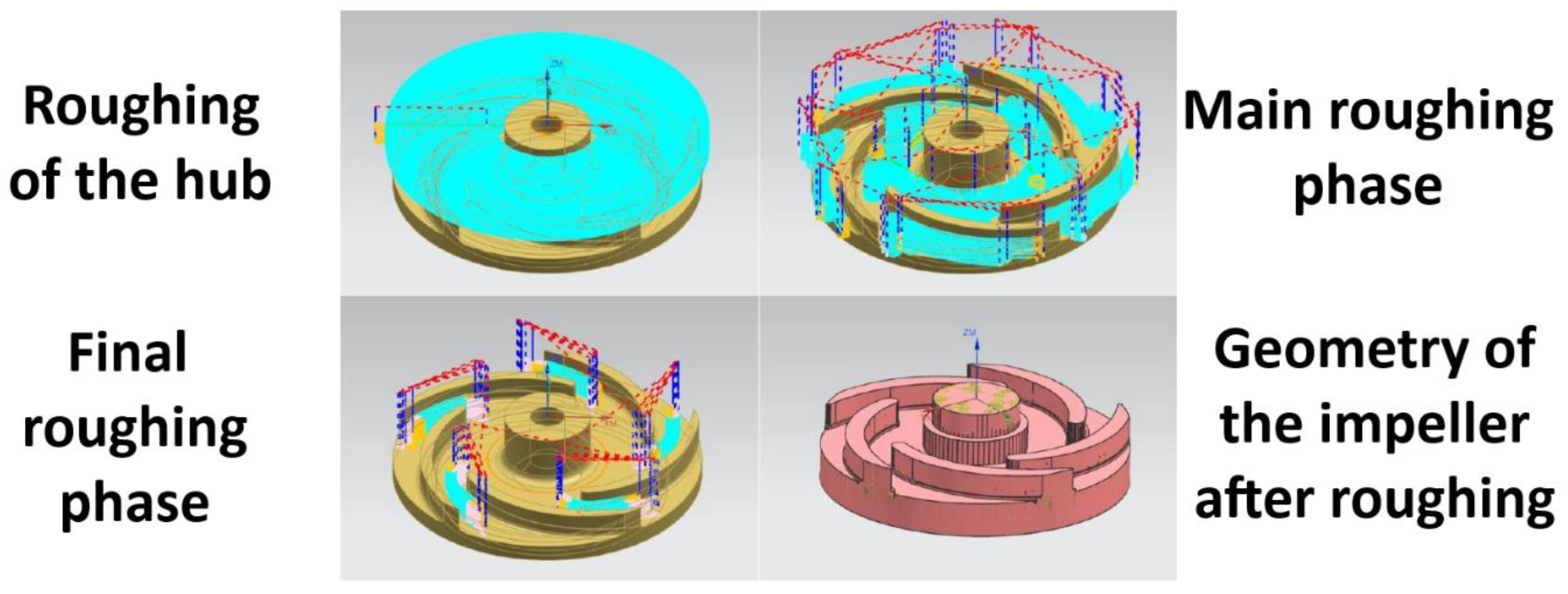
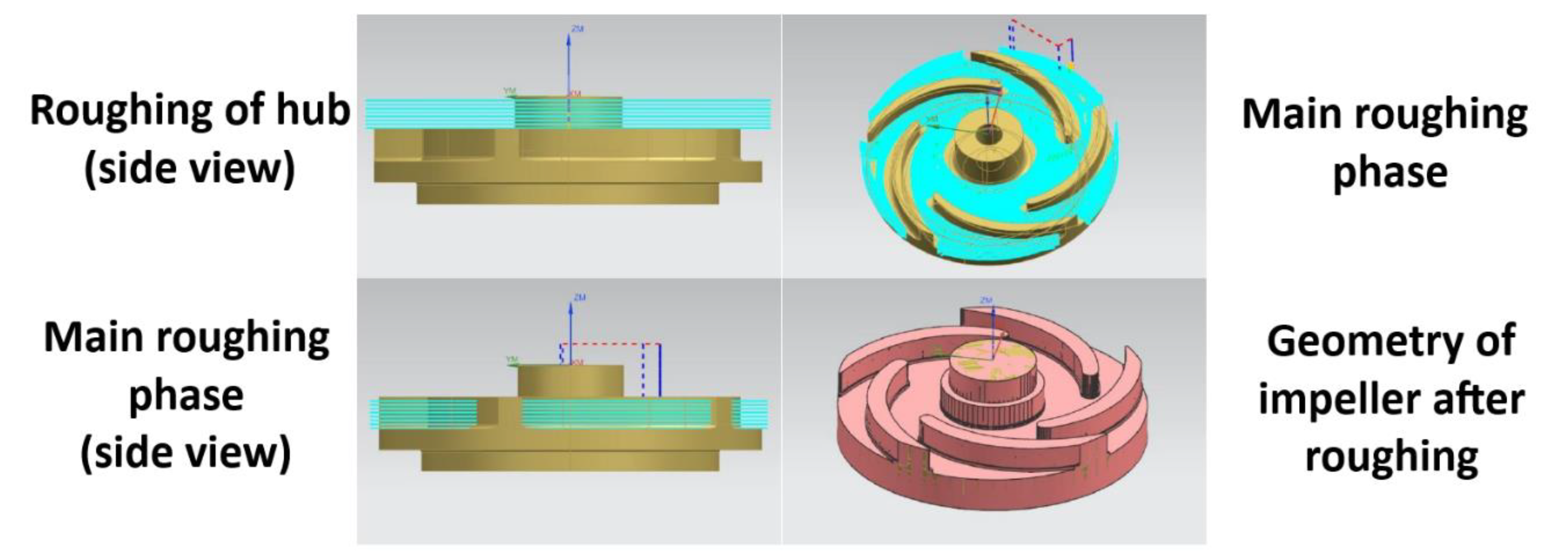
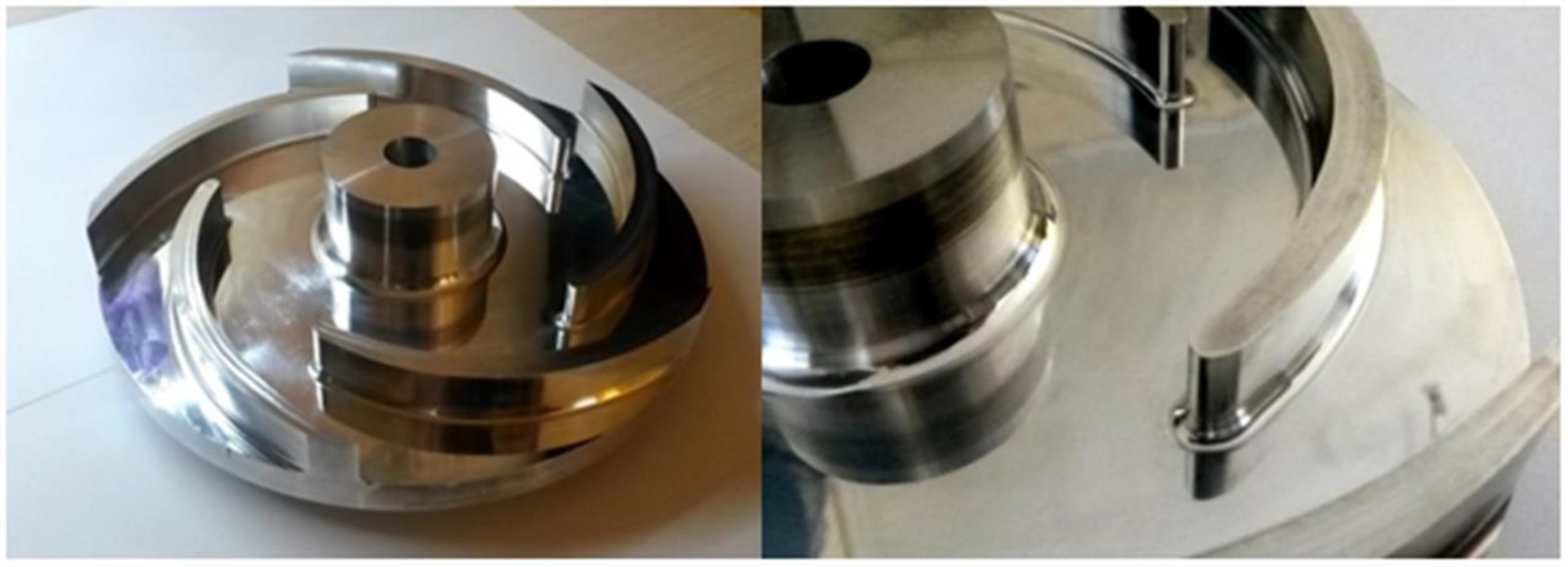
In the present work, the various stages of manufacturing of a radial pump impeller are presented in detail. At first, the machining processes required for the fabrication of the impeller are planned using dedicated CAM software. The manufacturing of the impeller is divided into three phases, namely, the roughing, semi-finishing, and finishing phase, and for each phase, the appropriate milling strategies, process parameters, cutting tools, and fixtures are determined, either using recommended values from manufacturers or the CAM software or by initial machining tests. After all phases are simulated in the environment of the CAM software, the appropriate G-code is produced and then the actual machining stage takes place in a three-axis vertical machining center. Finally, the manufactured impeller is evaluated according to its surface quality. Regarding the surface quality evaluation, a series of experiments is conducted under various spindle speed, axial depth of cut, and feed per tooth values in order to determine the optimum conditions for the finishing of the blades’ inner and outer surfaces. The stages of the manufacturing of the radial pump impeller are presented in a schematic in Figure 2.
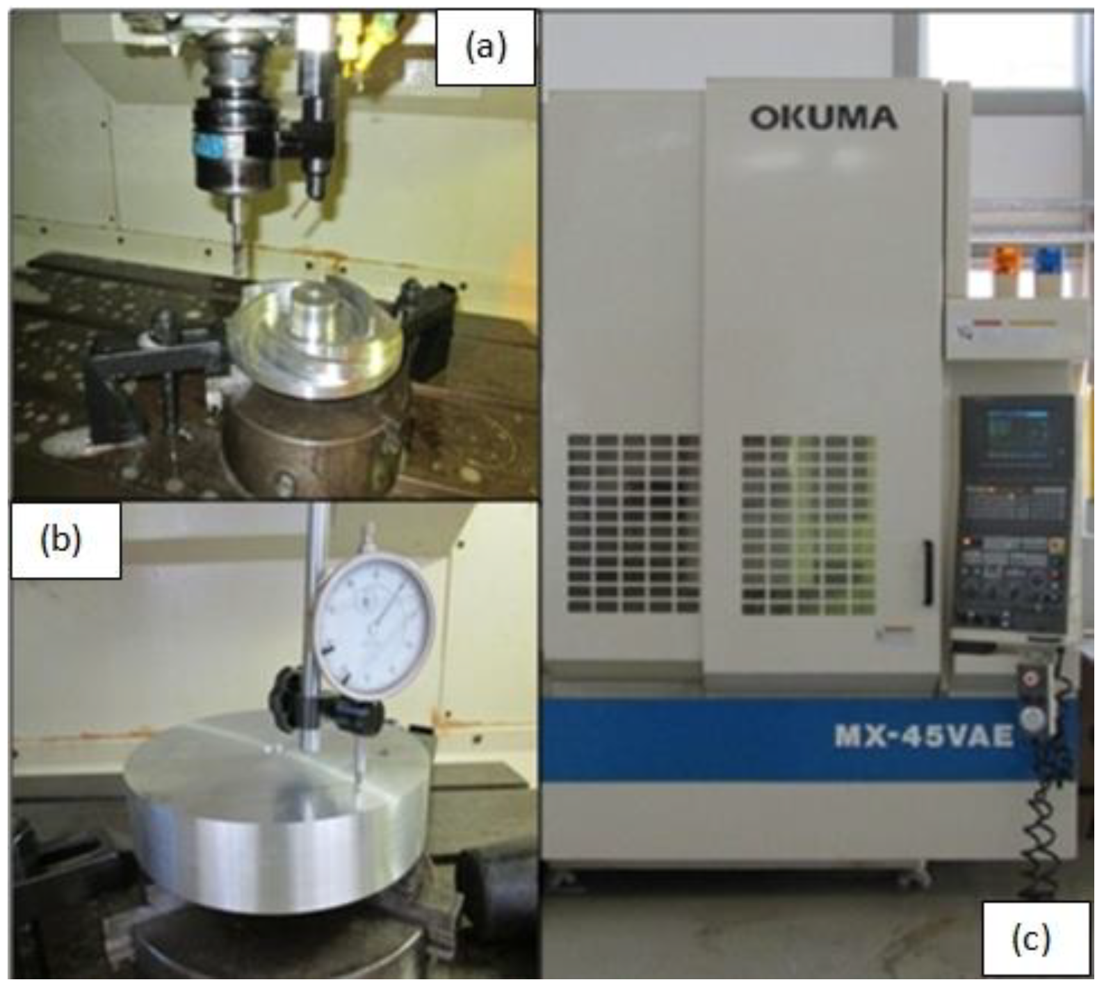
The manufacturing process of the radial pump impeller is carried out on a vertical CNC machining center; the CNC machining center, presented also in Figure 3, is OKUMA MX-45 VAE with an OSP7000M control unit with three-axis, maximum power 7.5 kW, and 10 μm accuracy. For high speed machining, during some of the manufacturing phases of the impeller, a GERARDI GSS-10 spindle speeder was employed, with capabilities of achieving a six-fold increase of spindle speed using planetary gear mechanism. In order to fix the cutting tools on the tool holder when spindle speeder is used, ER16 type collets were employed.
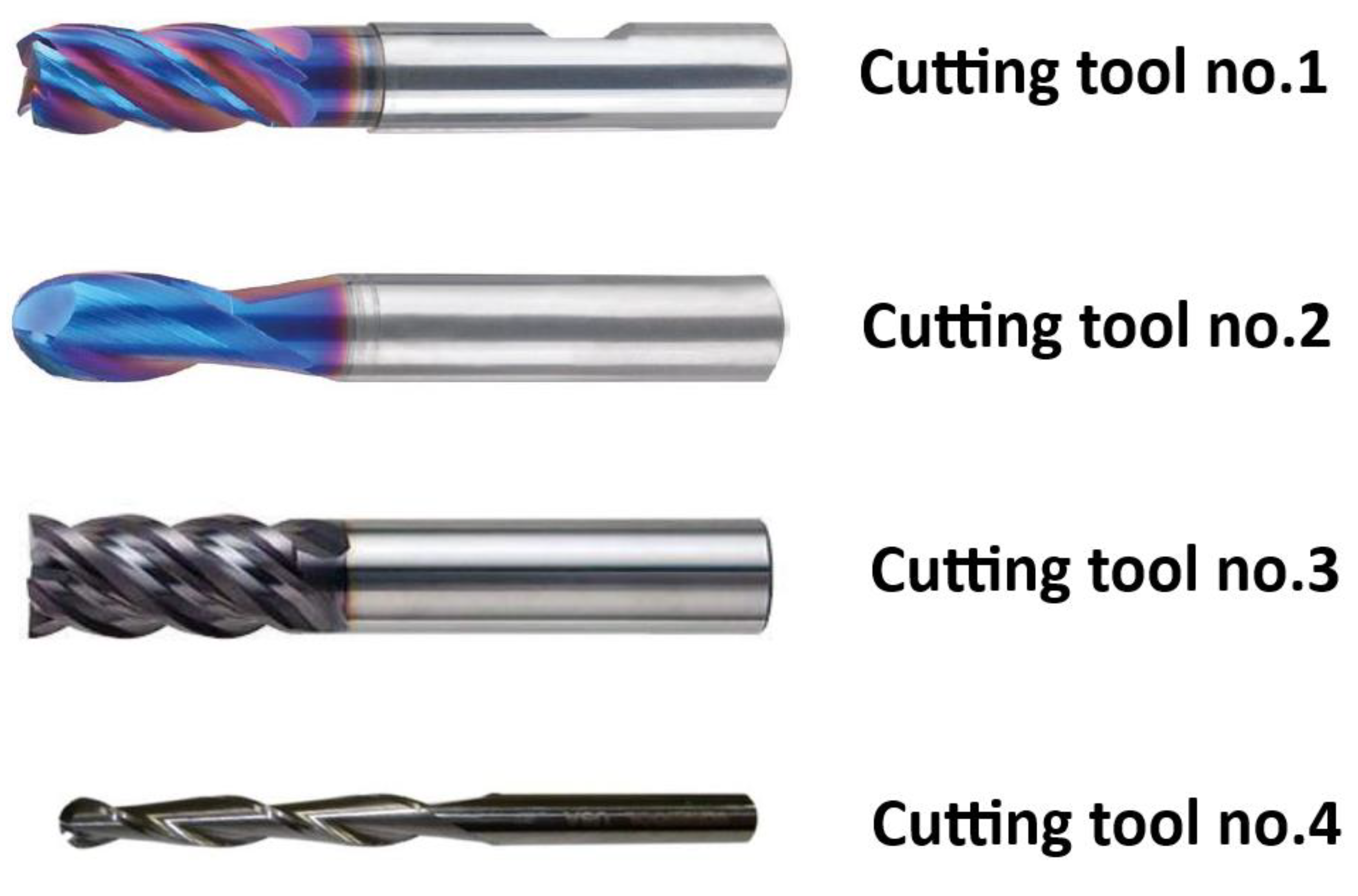
As it will be explained in detail in Section 3, four different cutting tools are employed in various phases of the machining process. The cutting tools are presented in Figure 4 and their characteristics are summarized in Table 1.
Cutting is performed under wet conditions by using P3 Multan S cutting fluid; this cutting fluid is semi-synthetic coolant mixed with water in a 1:3 ratio. Finally, the workpiece material for the radial impeller is Aluminum alloy 7075 (also denoted with the ISO name AlZn5.5MgCu). This aluminum alloy has zinc as the main alloying element and is of high strength and toughness, which is very frequently used in applications in the aviation industry [22,23]. It has low corrosion resistance with mechanical stress leading to brittle fracture—something that can be further treated with special heat treatments [23]. It can also be hardened with precipitation after heat treatment of solubilization, quenching, and aging [24]. The typical chemical composition of Al 7075 alloy is presented in Table 2.

3. Machining Processes for the Manufacturing of the Impeller

3.1. First Phase of Machining

Roughing is usually the first phase of the machining processes. This phase constitutes the main material removal phase, where the initial bulk material is removed up to a specific thickness until the second phase of semi-finishing will take place and, eventually, the final surface will be created after the finishing phase. Consequently, during this first phase, there are no strict requirements regarding surface roughness, as the main objective is the removal of a large quantity of material in as little machining time as possible. In the present work, a total of two different impellers were machined by different roughing conditions in order to evaluate two different strategies, namely the trochoidal and follow periphery strategy, and finally select the most appropriate among the two for the case of the manufacturing of the radial impeller.
For the case of the trochoidal milling strategy, depicted in Figure 5, roughing is performed with an axial depth of cut (denoted as ap) of 15 mm, step-over of 20%, and an end mill with 10 mm diameter as cutting tool. More specifically, these values were selected according to the recommendations of the CAM software for this milling strategy; the depth of cut value should be defined as less than two times the tool diameter, the step-over value should be defined less than 20% of the end mill diameter, feed per tooth (denoted as fz) can have high values, and cutting speed (denoted as vc) can also be defined 10 times higher than the other conventional strategies. This milling strategy can exploit the end mill cutting edge to a great extent, leading to uniform tool wear along the cutting edge, but also to increased machining time. In total, the roughing stage for the first impeller was performed in three steps. During the first step, the hub was created by peripheral milling, with an axial depth of cut of 15 mm and a step-over value of 1 mm. During the second step, the trochoidal method was employed with the aforementioned conditions. The third step was carried on to remove material in the space between adjacent blades, which could not be previously removed owing to the limited gap between them. When the trochoidal method was employed, spindle speed (denoted as N) was set to 5000 rpm and feed speed (denoted as vf) at 1000 mm/min. The total time required for this phase was calculated to be 32 min and 15 s.
For the second impeller the follow periphery milling strategy, available in the NX CAM software, was employed for roughing, as can be seen in Figure 6 With this method, the same spindle speed and feed speed values were selected as with the trochoidal method, namely 5000 rpm and 1000 mm/min, respectively, whereas depth of cut was 2 mm and step-over value was 2 mm. In this case, a carbide end mill with a diameter of 10 mm was employed. When the follow periphery strategy is employed, higher tool wear is observed closer to the lower part of the cutting edge, up to 2 mm, which is very different compared with the tool wear when the trochoidal milling strategy is employed. However, it is observed that the machining time is much lower using the follow periphery strategy. More specifically, the total time required for this phase was calculated to be 19 min and 45 s, almost half the time required for the trochoidal milling strategy. After the roughing process was completed, a material layer of 0.3 mm thickness remained at the floor surface of the impeller, as well as a layer of 2 mm at the blades surfaces and a layer of 5 mm at the hub.

3.2. Second Phase of Machining

The second phase of the machining process of the radial impeller was the semi-finishing phase, presented in Figure 7 During this phase, the same milling strategy and cutting conditions were selected for each of the two impellers that were previously processed with two different roughing strategies. For this phase of machining, three cutting tools were selected, both end mills and ball nose cutters. With the ball nose tool of 10 mm diameter, 7000 rpm spindle speed and feed speed of 500 mm/min was selected and then, with the ball nose cutter of 4 mm diameter, 6000 rpm spindle speed and feed speed of 200 mm/min was selected. The duration of the semi-finishing stage was 4 min and 10 s.

3.3. Third Phase of Machining

Finally, the finishing stage of machining process took place on the impellers, as depicted in Figure 8 Different cutting conditions were appropriately selected for various parts of the impeller in order to provide the maximum possible surface quality. For the upper part of the blades, 7000 rpm spindle speed and feed speed of 420 mm/min was selected with a ball nose cutting tool. Moreover, the bottom surface of the impeller was finished with the follow periphery method with a spindle speed of 7000 rpm and feed speed of 420 mm/min. Furthermore, the hub of the impeller was machined at two sub-stages, with a 10 mm diameter end mill with radial depth of cut 2 mm, spindle speed 7000 rpm, and feed speed values of 400 and 420 mm/min.
Especially, the cutting conditions for profile milling strategy on blades surfaces are calculated by the Taguchi method from the environment of Minitab 17 statistical software. Using the Taguchi method, orthogonal arrays are employed to investigate how different factors of a process can affect the mean and average of a response. Using the Taguchi method, it is possible to avoid using the full factorial approach, which involves all the possible combinations between the levels of factors and conduct experiments using a minimum number of these combinations. In the present work, three parameters, namely, spindle speed, axial depth of cut, and feed per tooth, are desired to be varied at four levels each, thus from Minitab Software, it is deduced that the Taguchi L16 orthogonal array should be employed. The selected range of parameters’ values is in accordance with the cutting tool manufacturer’s specifications for machining aluminum, and all different combinations are summarized in Table 3. It is to be noted that, in order to be able to use 16 different conditions, different conditions were applied on the external and internal surfaces of blades of two different impellers.

4. Impeller Manufacturing and Evaluation

4.1. Manufacturing Processes of the Impeller

After the various phases of the machining process were determined in the CAM software, the setup of the three-axis CNC machining center is performed. As the initial bulk is a cylindrical workpiece, it was fixed on the machine tool with a chuck. After the cutting tools were selected and the relevant G-code was loaded onto the CNC machine, the first phase of the machining process took place, according to the predefined plan.
It is noteworthy to mention that, during the semi-finishing phase, when the outer surface of the five blades was machined with the 4 mm diameter ball nose cutter, the chattering phenomenon occurred with direct consequences on the condition of the cutting tool and the surface quality of the blades, as can be seen in Figure 9 In this case, several alterations to the initially chosen process conditions were conducted, mainly reducing the spindle speed and feed speed to values as low as 20% of the initial ones, namely spindle speed of 1200 rpm and feed of 40 mm/min. The impact of the chatter to the surface quality of the blades was quantified through surface roughness measurement and is presented in Section 4.2. After the semi-finishing phase was completed, the finishing process took place with the predefined process conditions for each area of the impeller.
After the finishing phase was completed, the surface quality of the radial impeller was evaluated, and then the produced radial impellers were ground in order to render an excellent surface finish, as can be seen in Figure 10 It is to be noted that the grinding stage does not constitute a part of the investigation regarding the optimum conditions for improving surface quality during the finishing stage, but it was necessary to be performed before using the produced part in a real pumping facility.

4.2. Evaluation of Surface Quality of the Impeller

After the machining process of the impeller is completed, it is considered important to evaluate the quality of the produced surfaces during the finishing phase. Surface roughness is measured using a Taylor Hobson Surtronic 3+ portable profilometer. In order to facilitate the measurement process, the impeller was fixed on a lathe chuck and the profilometer was positioned on the moving part of the lathe, as can be seen in Figure 11.
On each blade surface, surface measurements were repeated four times in different positions of the blades, as can be seen in Figure 12 The results are summarized in Table 4 and also presented in Figure 13.
Apart from the blades surfaces, the surface roughness on the upper surface of the blades and the lower surface of the impeller was measured at 0.2 μm. Furthermore, the surface roughness was also measured on the blade that exhibited chatter. The results are presented in Table 5 It is to be noted that, in order to avoid chattering, feed per tooth values were decreased to 20% of the initial value in the experiments presented in Table 4. The considerably increased value of surface roughness when chattering occurs in comparison with the significantly lower values achieved with more favorable conditions are consistent with the observations conducted in the stereoscope, presented in Figure 14 and Figure 15.
After the surface roughness results were obtained for all experimental conditions, statistical analysis was conducted and a regression model was derived in order to determine the correlation between process parameters and surface roughness, as well as determine the optimum process parameters. The results of the analysis of variance (ANOVA) are summarized in Table 6.
As can be seen from Table 6 that the most important parameters, which are statistically significant, are spindle speed and feed per tooth, as their p-value is below 0.05 and sum of squares is larger than that of the other factors.
Afterwards, a regression model was able to be developed as follows:
R a = 0.6925 0.000021 N + 0.0015 a p + 23.18 f z 0.000001 ( N a p ) 0.000225 ( N f z ) + 1.149 ( a p f z ) + 0.00063 a p 2 129 f z 2
For the evaluation of the regression model, the coefficient of determination (R2), as well as R2-adjusted and R2-predicted, should be calculated. The R2-adjusted factor is particularly useful in cases where the regression model contains multiple inputs as its value does not increase when new variables are introduced, unless they can really contribute to the explanation of the variance of the model. The R2-predicted value can indicate the capability of the regression model to predict new data as it is calculated by removing successive observations and re-calculating the model equation. The developed model exhibited a high level of accuracy as the value of R2 was 99.74%, R2-adjusted value was 99.35%, and R2-predicted value was 98.62%.
From the main effects plot, the effect of process parameters on surface roughness during the finishing process of the blades can be determined. From Figure 16, it can be seen that, as anticipated, an increase of spindle speed results in a decrease of surface roughness, as well as the reduction of feed per tooth value. However, the axial depth of cut does not affect the surface roughness considerably. At the same time, ANOVA results indicate that the feed per tooth is a slightly more important parameter than the spindle speed, but both are significantly more important than the axial depth of cut, indicating that considerable improvement in surface roughness can be obtained by regulating these two parameters. Finally, the optimum process parameter levels are as follows: 18,000 rpm spindle speed, 4 mm axial depth of cut, and 0.0042 mm/tooth feed per tooth. These findings indicate that the use of spindle speeder for the finishing process of the radial impeller is necessary, as it enabled a considerable decrease of the surface roughness values. After the optimum parameters for the finishing stage of the blades are selected, the recommended process conditions for every phase of the manufacturing process are determined.

5. Conclusions

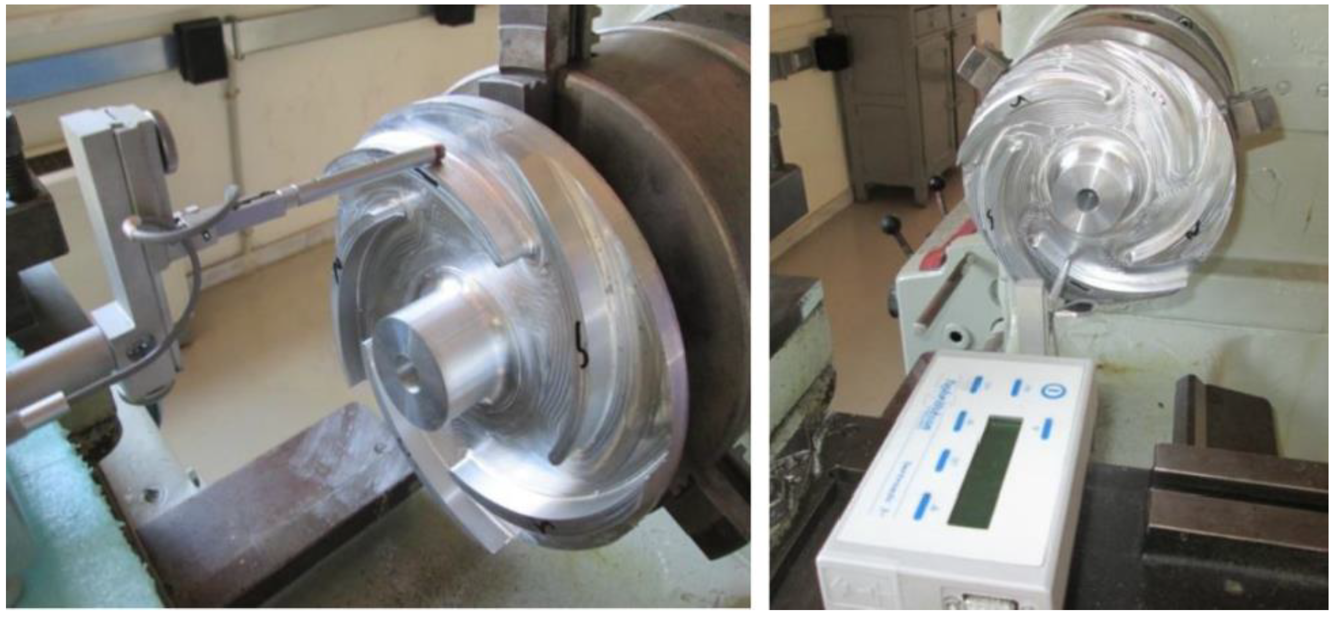
In the present work, the manufacturing process of a radial pump impeller is discussed and described, including the design of the manufacturing process, their implementation, and the evaluation of the machined product quality.
At first, the machining operations for the manufacture of the radial impeller are designed in NX CAM software. During the three main phases, namely, roughing, semi-finishing, and finishing, the milling strategies, cutting tools, and process conditions required are determined before the actual machining process is implemented in the vertical CNC machining center.
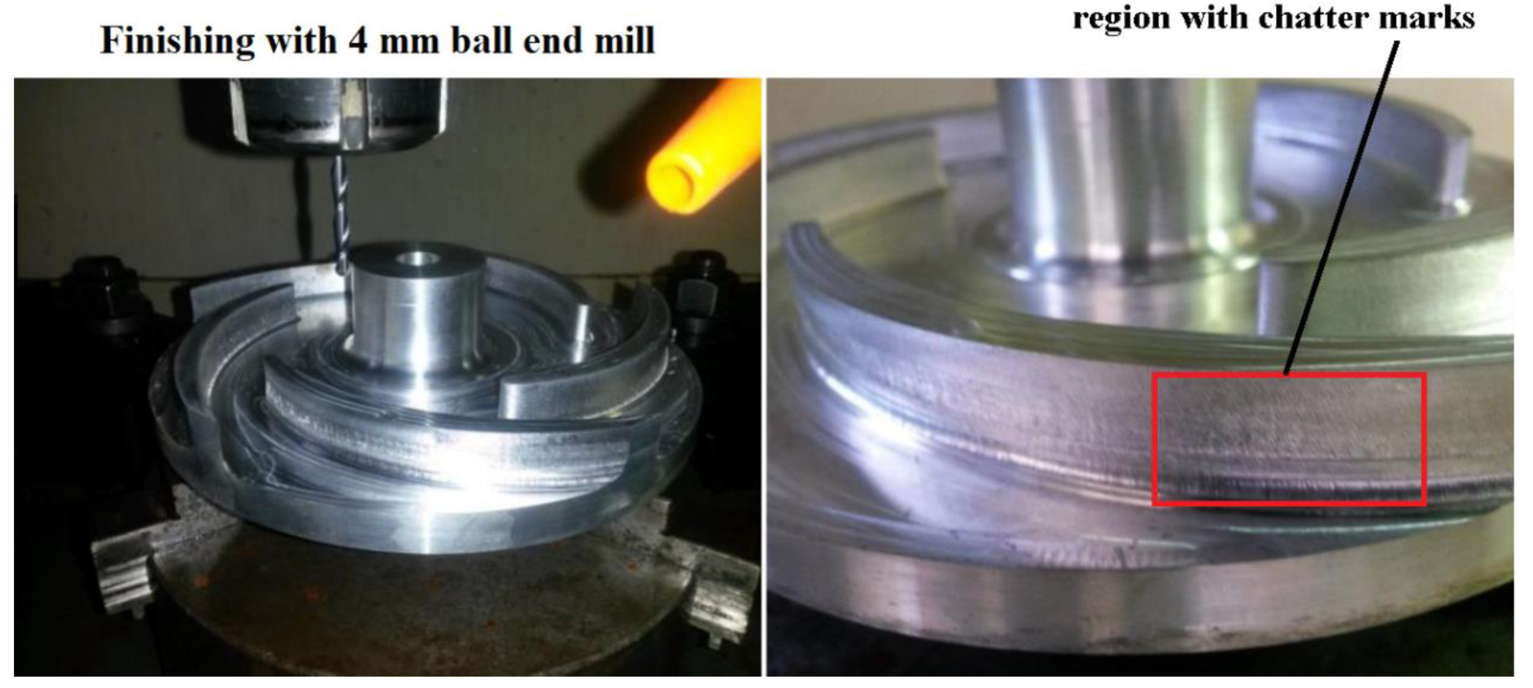
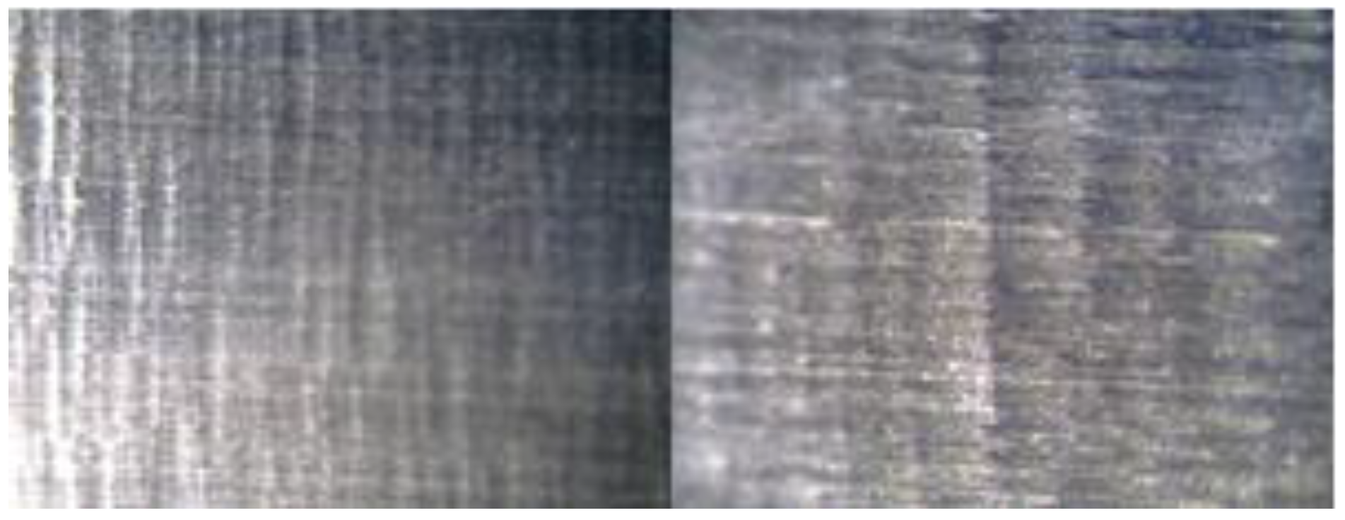
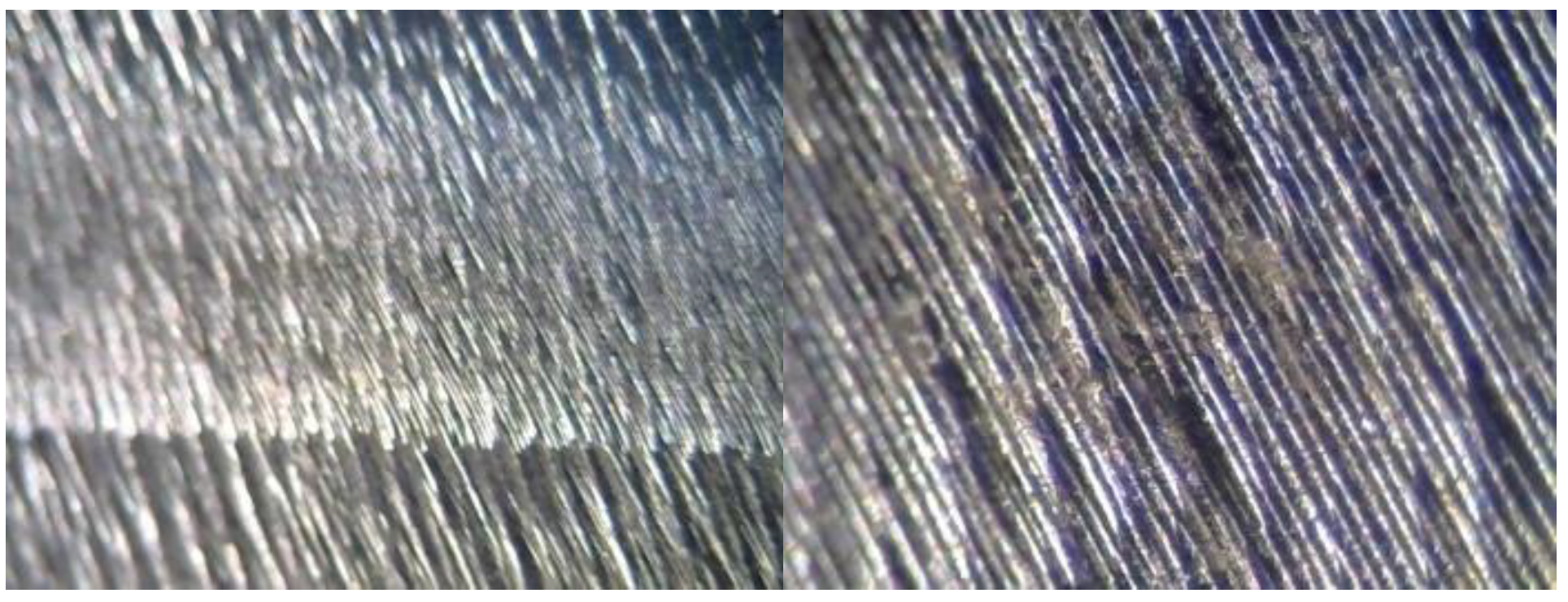
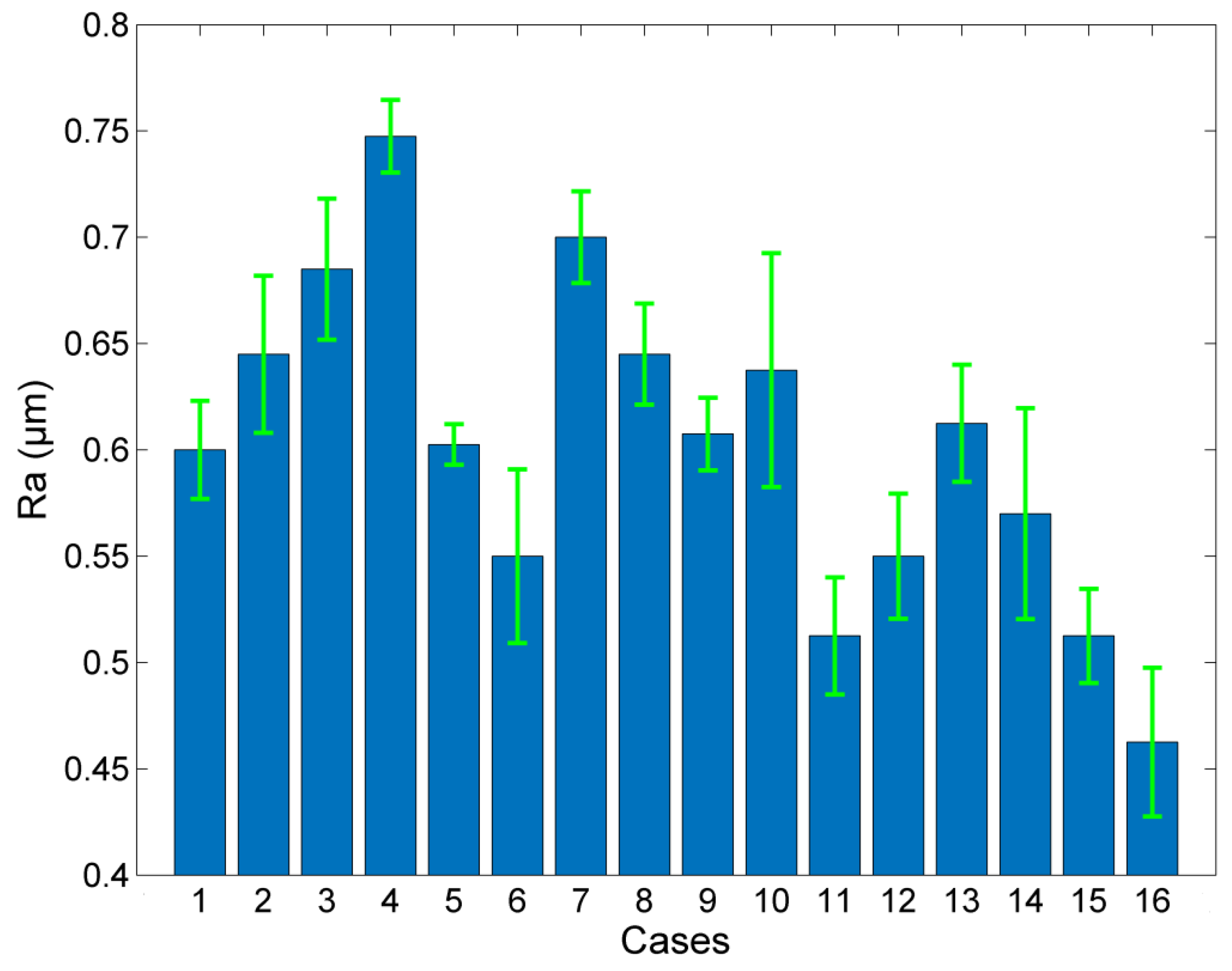
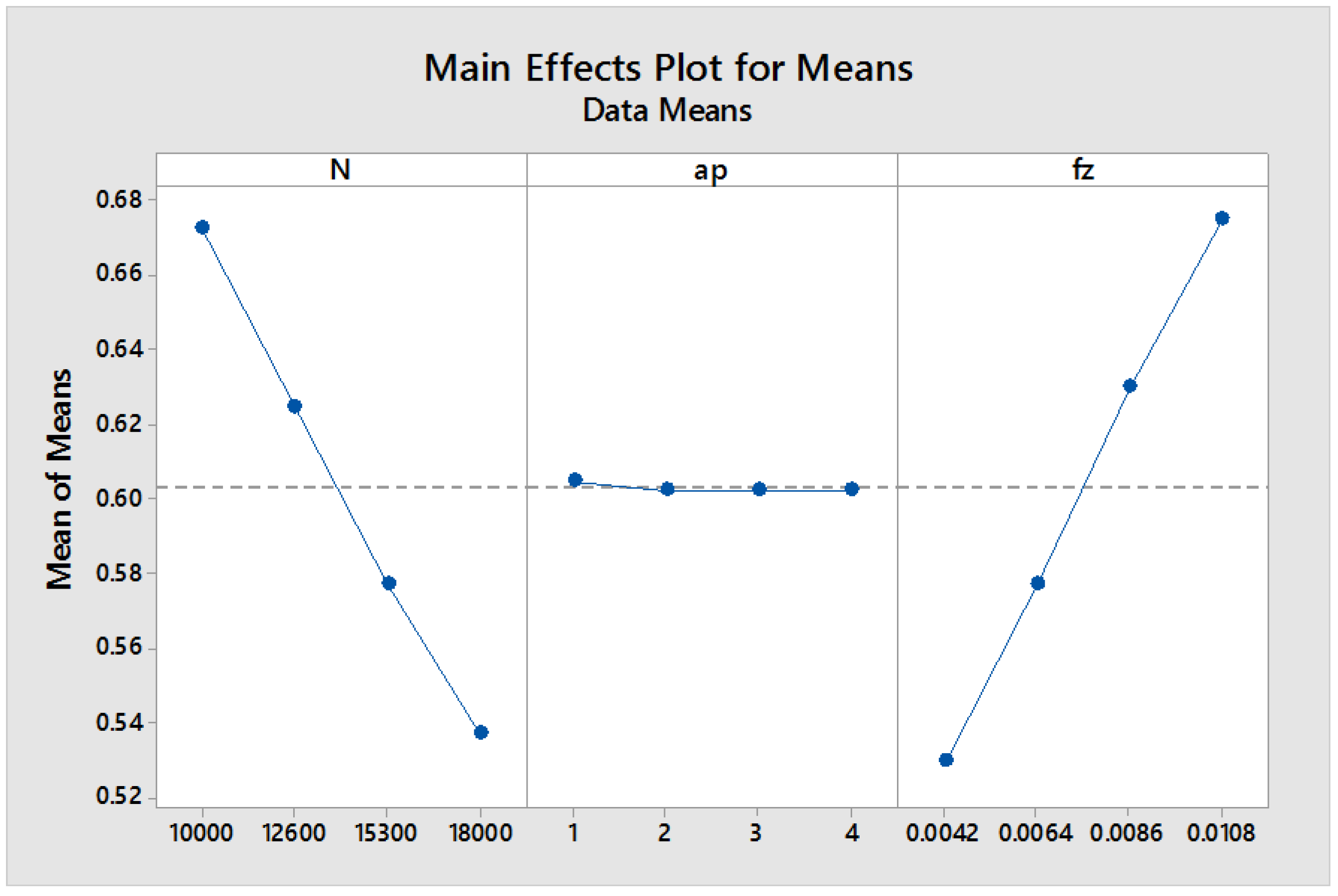
It was found that the follow periphery strategy, with a 10 mm diameter end mill with a spindle speed of 7000 rpm, feed rate of 2000 mm/min, and depth of cut of 2 mm, is the most favorable strategy during roughing, as it leads to lower machining time and minimal wear of the cutting edge. During the semi-finishing phase, the process conditions were altered in order to avoid chatter. Although when the 10 mm diameter end mill was used, the milling conditions were the same as in the design stage, namely spindle speed of 7000 rpm and feed rate of 500 mm/min, the milling conditions for the case of 4 mm diameter ball end cutting tool, the final values of spindle speed and feed rate were reduced considerably at 1200 rpm and 40 mm/min, respectively. Finally, the investigation regarding the optimum process conditions during finishing of the impeller blades, which was designed by L16 Taguchi orthogonal array, indicated that the spindle speed and feed per tooth are the most important parameters for the control of surface roughness, as anticipated, whereas the effect of axial depth of cut was insignificant. Spindle speed and feed per tooth were identified as the most important parameters. The recommended values for spindle speed, axial depth of cut, and feed per tooth determined from the investigation were 18,000 rpm, 4 mm, and 0.0042 mm/tooth, respectively, and it was shown that, in this case, the obtained surface roughness was as low as 0.46 μm. These results indicate the importance of the use of the spindle speeder, as it enabled a considerable decrease of surface roughness during the finishing process of the radial impeller.

Author Contributions

Conceptualization, N.I.G. and A.P.M.; Data curation, F.I.S. and N.E.K.; Formal analysis, F.I.S. and N.E.K.; Funding acquisition, A.P.M.; Investigation, F.I.S. and N.I.G.; Methodology, N.I.G., N.E.K. and A.P.M.; Resources, N.I.G. and A.P.M.; Software, F.I.S. and N.E.K.; Supervision, A.P.M.; Validation, N.E.K.; Visualization, F.I.S.; Writing—original draft, F.I.S.; Writing—review editing, N.I.G. and A.P.M. All authors have read and agreed to the published version of the manuscript.

Funding

This research received no external funding.

Conflicts of Interest

The authors declare no conflict of interest.

References

  1. Kumar, S.V.; Mani, V.G.S.; Devraj, N. Production Planning and Process Improvement in an Impeller Manufacturing using Scheduling and OEE Techniques. Procedia Mater. Sci. 2014, 5, 1710–1715. [Google Scholar] [CrossRef] [Green Version]
  2. Tang, M.; Zhang, D.; Luo, M.; Wu, B. Tool Path Generation for Clean-up Machining of Impeller by Point-searching Based Method. Chin. J. Aeronaut. 2012, 25, 131–136. [Google Scholar] [CrossRef] [Green Version]
  3. Bohez, E.L.J.; Senadhera, S.D.R.; Pole, K.; Duflou, J.R.; Tar, T. A Geometric Modeling and Five-Axis Machining Algorithm for Centrifugal Impellers. J. Manuf. Syst. 1997, 16, 422–436. [Google Scholar] [CrossRef]
  4. Lee, J.H.; Kang, S.H.; Yang, D.Y. Novel forging technology of a magnesium alloy impeller with twisted blades of micro-thickness. CIRP Ann. 2008, 57, 261–264. [Google Scholar] [CrossRef]
  5. Young, H.T.; Chuang, L.C. An integrated machining approach for a centrifugal impeller. Int. J. Adv. Manuf. Technol. 2003, 21, 556–563. [Google Scholar] [CrossRef]
  6. Kaino, T. Machining technology for large impellers of centrifugal compressors. Kobelco Technol. Rev. 2015, 33, 56–60. [Google Scholar]
  7. Wu, S.; Yang, L.; Liu, X.; Zheng, M.; Li, R. Study on performance of integral impeller stiffness based on five-axis machining system. Procedia CIRP 2016, 56, 485–490. [Google Scholar] [CrossRef] [Green Version]
  8. Fan, H.Z.; Xi, G. Optimizing tool-path generation for three-axis machining of a sculptured impeller blade surface. Proc. Inst. Mech. Eng. Part B J. Eng. Manuf. 2012, 226, 43–51. [Google Scholar] [CrossRef]
  9. Fan, H.Z.; Wang, S.J.; Xi, G.; Cao, Y.L. A novel tool-path generation method for five-axis flank machining of centrifugal impeller with arbitrary surface blades. Proc. Inst. Mech. Eng. Part B J. Eng. Manuf. 2017, 231, 155–166. [Google Scholar] [CrossRef]
  10. Li, M.; Liu, X.; Jia, D.; Liang, Q. Interpolation using non-uniform rational B-spline for the smooth milling of ruled-surface impeller blades. Proc. Inst. Mech. Eng. Part B J. Eng. Manuf. 2015, 229, 1118–1130. [Google Scholar] [CrossRef]
  11. Fan, H.F.; Xi, G. Efficient tool path generation for five axis machining of a difficult machined centrifugal impeller. Adv. Mech. Eng. 2017, 9, 1–10. [Google Scholar] [CrossRef]
  12. Fan, H.Z.; Xi, G.; Wang, W.; Cao, Y.L. An efficient five-axis machining method of centrifugal impeller based on regional milling. Int. J. Adv. Manuf. Technol. 2016, 87, 789–799. [Google Scholar] [CrossRef]
  13. Wang, G.; Li, W.L.; Rao, F.; He, Z.R.; Yin, Z.P. Multi-parameter optimization of machining impeller surface based on the on-machine measuring technique. Chin. J. Aeronaut. 2019, 32, 2000–2008. [Google Scholar] [CrossRef]
  14. Arriaza, O.V.; Kim, D.-W.; Lee, D.Y.; Suhaimi, A. Trade-off analysis between machining time and energy consumption in impeller NC machining. Robot Comput.-Integr. Manuf. 2017, 43, 164–170. [Google Scholar] [CrossRef]
  15. Chaves-Jacob, J.; Poulachon, G.; Duc, E. Optimal strategy for finishing impeller blades using 5-axis machining. Int. J. Adv. Manuf. Technol. 2012, 58, 573–583. [Google Scholar] [CrossRef]
  16. Peng, S.; Li, T.; Wang, X.; Dong, M.; Liu, Z.; Shi, J.; Zhang, H. Toward a sustainable impeller production: Environmental impact comparison of different impeller manufacturing methods. J. Ind. Ecol. 2017, 21, S216–S229. [Google Scholar] [CrossRef] [Green Version]
  17. Young, H.T.; Chuang, L.C.; Gerschwiler, K.; Kamps, S. A five-axis rough machining approach for a centrifugal impeller. Int. J. Adv. Manuf. Technol. 2004, 23, 233–239. [Google Scholar] [CrossRef]
  18. Tang, Q.C.; Yin, S.H.; Geng, J.X.; Luo, H.; Chen, Y.P. The study of variational feed rate in 4-axis machining of blades. Int. J. Precis. Eng. Manuf. 2018, 19, 1419–1428. [Google Scholar] [CrossRef]
  19. Heo, E.Y.; Kim, D.W.; Kim, B.H.; Jang, D.K.; Chen, F.F. Efficient rough-cut plan for machining an impeller with a 5-axis NC machine. Int. J. Comput. Integr. Manuf. 2008, 21, 971–983. [Google Scholar] [CrossRef]
  20. Kim, D.W.; Suhaimi, M.A.; Kim, B.M.; Cho, M.H.; Chen, F.F. Rough cut machining for impellers with 3-axis and 5-axis NC machines. In Advances in Sustainable and Competitive Manufacturing Systems, Lecture Notes in Mechanical Engineering, 1st ed.; Azevedo, A., Ed.; Springer Science & Business Media: Chan, Switzerland, 2013; pp. 609–616. [Google Scholar]
  21. Mentzos, M.D.; Markopoulos, A.P.; Galanis, N.I.; Margaris, D.P.; Manolakos, D.E. Design, Numerical Analysis and Manufacture of Radial Pump Impellers with Various Blade Geometries. Int. Rev. Mech. Eng. 2015, 9, 104–111. [Google Scholar] [CrossRef]
  22. Kumar, R.; Dhiman, S. A study of sliding wear behaviors of Al-7075 alloy and Al-7075 hybrid composite by response surface methodology analysis. Mater. Des. 2013, 50, 351–359. [Google Scholar] [CrossRef]
  23. Li, J.F.; Peng, Z.W.; Li, C.X.; Jia, Z.Q.; Chen, W.J.; Zheng, Z.Q. Mechanical properties, corrosion behaviors and microstructures of 7075 aluminum alloy with various aging treatments. Trans. Nonferrous Met. Soc. China 2008, 18, 755–762. [Google Scholar] [CrossRef]
  24. Rajan, K.; Wallace, W.; Beddoes, J.C. Microstructural study of a high-strength stress-corrosion resistant 7075 aluminium alloy. J. Mater. Sci. 1982, 17, 2817–2824. [Google Scholar] [CrossRef]
Figure 1. Geometry of the radial impeller with basic dimensions.
Machines 08 00001 g001
Figure 2. Schematic of the steps required for the design and manufacture of the radial impeller. CAM, computer-aided manufacturing.
Machines 08 00001 g002
Figure 3. (a) Spindle speeder, (b) workpiece, and (c) computer numerical control (CNC) milling machine used for impeller manufacturing.
Machines 08 00001 g003
Figure 4. Cutting tools employed in the present work.
Machines 08 00001 g004
Figure 5. Snapshots of the roughing phase of the radial impeller using the trochoidal milling strategy.
Machines 08 00001 g005
Figure 6. Snapshots of the roughing phase of the radial impeller using the follow periphery strategy.
Machines 08 00001 g006
Figure 7. Snapshots of the semi-finishing phase of the radial impeller.
Machines 08 00001 g007
Figure 8. Snapshots of the finishing phase of radial impeller.
Machines 08 00001 g008
Figure 9. Characteristic marks on the outer surface of the impeller blades owing to chatter during the semi-finishing phase.
Machines 08 00001 g009
Figure 10. Surface quality of the radial impeller after grinding.
Machines 08 00001 g010
Figure 11. Roughness measurement: on the external surface of blades (left), on the internal surface of blades (right).
Machines 08 00001 g011
Figure 12. Roughness measurement points on the external and internal surface of the blades.
Machines 08 00001 g012
Figure 13. Average Ra values for all experimental cases.
Machines 08 00001 g013
Figure 14. External blade surface after finishing test no. 16.
Machines 08 00001 g014
Figure 15. External blade surface when the chattering phenomenon occurs.
Machines 08 00001 g015
Figure 16. Main effects plot for means for surface roughness Ra.
Machines 08 00001 g016
Table 1. Characteristics of the cutting tools employed in the present work.
No of Cutting ToolTypeDiameter (mm)Material
1End mill10Cemented Carbide H10
2Ball nose10Cemented Carbide H10
3End mill10Cemented Carbide H10
4Ball nose4Cemented Carbide H10
Table 2. Typical chemical composition of aluminum alloy 7075 [22].
Zn (%)Mg (%)Cu (%)Si (%)Fe (%)Mn (%)Cr (%)Ti (%)OtherAl (%)
5.672.211.350.400.300.080.080.060.06Balance
Table 3. Process conditions for the finishing of impeller blades.
No of Experimental TestSpindle Speed (rpm)ap (mm)fz (mm/tooth)
110,00010.0042
210,00020.0064
310,00030.0086
410,00040.0108
512,60010.0064
612,60020.0042
712,60030.0108
812,60040.0086
915,30010.0086
1015,30020.0108
1115,30030.0042
1215,30040.0064
1318,00010.0108
1418,00020.0086
1518,00030.0064
1618,00040.0042
Table 4. Surface roughness measurement on impeller blade surfaces.
Process ConditionsRoughness on Measurement Points (μm)
No of MeasurementSpindle Speed (rpm)ap (mm)fz (mm/tooth)1234Average Ra (μm)Standard Deviation of Ra (μm)
110,00010.00420.620.580.580.620.600.02
210,00020.00640.660.620.610.690.650.04
310,00030.00860.690.660.660.730.690.03
410,00040.01080.750.730.740.770.750.02
512,60010.00640.610.590.600.610.600.01
612,60020.00420.580.510.520.590.550.04
712,60030.01080.700.690.680.730.700.02
812,60040.00860.660.630.620.670.650.02
915,30010.00860.610.590.600.630.610.02
1015,30020.01080.650.600.590.710.640.06
1115,30030.00420.530.480.500.540.510.03
1215,30040.00640.570.520.530.580.550.03
1318,00010.01080.630.600.580.640.610.03
1418,00020.00860.600.500.570.610.570.05
1518,00030.00640.520.490.500.540.510.02
1618,00040.00420.480.450.420.500.460.04
Table 5. Surface roughness measurement of a blade where chatter occurred.
Process ConditionsRoughness on Measurement Points (μm)
No of MeasurementSpindle Speed (rpm)ap (mm)fz (mm/tooth)1234Average Ra (μm)Standard Deviation of Ra (μm)
110,00010.0214.167.144.541.994.462.11
Table 6. Analysis of variance (ANOVA) table for the surface roughness measurements.
SourceDFAdj SSAdj MSF-Valuep-Value
Regression90.0887110.009857253.790.000
N10.0003310.0003318.530.027
ap10.0000000.0000000.010.928
fz10.0003790.0003799.760.020
N * ap10.0000730.0000731.890.218
N * fz10.0000150.0000150.390.554
ap * fz10.0000560.0000561.440.275
N210.0000830.0000832.140.194
ap210.0000060.0000060.160.702
fz210.0000060.0000060.160.702
Error60.0002330.0000390.16
Total150.088944

