1. Introduction
The rapid development and growth of the wind energy industry has resulted in the installation of a significant fleet of onshore and offshore wind turbines across the world. The current promotion of wind electricity seems to indicate that more wind farms will be required in the near future, comprising units with larger power outputs that are mainly located offshore. Therefore, wind farm profitability must be increased by ensuring that wind turbines (WT) operate at a high capacity. Thus, proper operation and maintenance (O&M) is critical for maximizing the returns on the wind investments and for optimizing the total cost of ownership (TCO). This strategy seeks to minimize the production costs per unit of energy generated and to improve the turbine performance [
1].
In this sense, condition monitoring (CM) systems have been developed to detect anomalies with the goal of minimizing machine downtime and maximizing availability. The early detection of faults is crucial for performing predictive (condition-based) maintenance on units in a wind farm [
2,
3,
4,
5,
6]. Nevertheless, the complexity of the WTs, which are subjected to variable loads and speeds and are made with flexible components, such as the blades [
7], challenges the effectiveness of such systems. Among various methods [
8], assessing a machine’s condition based on its measured vibrations is one of the most reliable techniques, as the vibration levels of the wind turbines significantly influence the stress and fatigue of the components. This method has been extensively utilized in rotating machines, producing effective results in various types of industrial machines. However, the traditional processes and procedures that were developed in other industries, such as the oil and gas, hydropower, or nuclear power industries, are not valid for the wind industry, as the machine design, operation, and environment differ significantly.
Initially, relevant operation parameters were continuously monitored using the integrated supervisory control and data acquisition (SCADA) system [
9,
10]. Then, acquiring and measuring vibrations at high frequency rates using dedicated systems was found to be more reliable for evaluating the states of the various components of the drive train and the nacelle/tower system [
11,
12,
13]. In part, this method was utilized due to the multiple drive train rotating speeds and the rapid evolution of their incipient failures. Recently, new signal processing methods have been developed and tested to overcome the difficulty of applying traditional vibration analyses [
14,
15,
16], largely because WTs are submitted to complex sources of vibration. These excitations are due to wind loads on the rotor blades and the tower, the inertial forces of the rotating parts, the natural frequencies of various components, the mechanical forces in the power transmission system (including gear meshing processes) and the electromagnetic forces acting on the generator. Moreover, the rotor shaft turns at low speeds, the wind loads are stochastic, and the regulation system also induces transient conditions and unsteadiness.
To establish a CM system that is based on vibrations, the only reference that is currently available is the Association of German Engineers (VDI) standard VDI 3834 [
17]. This standard provides criteria and recommendations regarding the measurement and evaluation of the mechanical vibrations of onshore wind energy turbines with gears and components. However, the suggested values for evaluating the vibration levels are not suitable for the early detection of faults. Thus, if threshold values are exceeded, specific causes cannot be identified in detail. The vibratory behavior of a turbine depends on the manufacturer, design, and installation type. In all cases, it is imperative to account for the entire wind turbine, including the drive train components, rotor blades, nacelle, and tower. The resulting vibration behavior depends on the individual response of each part, the interactions throughout the entire wind energy installation, the resonance conditions, the types and ranges of excitation or loads, and the operating scenario.
The main objective of this study is to determine whether the vibration content of the drive train components measured during steady conditions is repetitive and if it follows a defined pattern that is based on the entire range of operating conditions. This objective is achieved by comparing WTs with the same design and characteristics. These WTs have been monitored in exactly the same positions using the same type of CM system over a sufficiently long period of time. The analysis steps are as follows:
detect and identify the most relevant frequency peaks using the median power spectrum at each measurement position based on the particular drive train kinematics;
determine whether differences exist between the measurement points and assess the sensitivity to different sources of excitation calculating the mean peak amplitudes and their deviations; and,
establish the dependency of the vibration amplitudes on the wind speed.
The identification of the WT vibration signature is necessary to guarantee a successful CM system. A well-designed WT in good condition will exhibit a certain level of vibration depending upon the machine design and operating conditions. This information must be used as a reference to easily detect the occurrence of new frequency peaks or variations in existing frequencies. Frequency variations indicate changes in the machine condition due to incipient failures or increased component wear. Trend analyses of the narrow band frequencies around these peaks can be used to manage maintenance strategies and minimize or eliminate problems.
2. Machines and Measurement System Description
2.1. Wind Farm Configuration
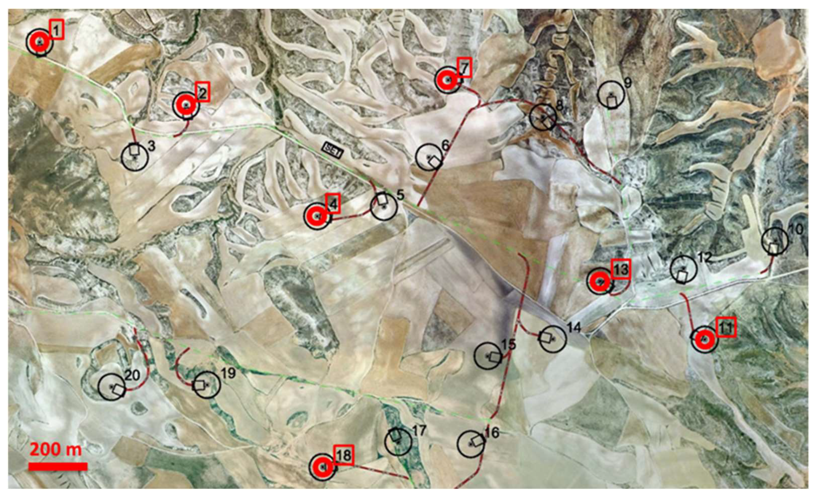
The studied WTs are located at the same onshore wind farm. Of the 20 total WTs, we selected seven machines with the same speed ratio and manufacturer (numbers 1, 2, 4, 7, 11, 13, and 18). Their relative locations in the farm are illustrated in
Figure 1, which shows the units from a topographic view. The minimum distance between any pair of units is more than 200 m.
2.2. Wind Turbine Specifications
Each WT consists of a generator coupled to a rotor via a gearbox. The conical tubular style tower is constructed from steel, while the foundation is made of concrete. The rotor shaft is supported by two bearings separated from the gearbox. All of the wind turbines use the same 50 Hz, four-pole generator driven by a three-stage planetary-helical gearbox (gearbox with one planetary stage and two additional parallel-shaft stages). Four different gearbox models are installed among the units. In addition, the turbines have horizontal-axis rotors with three blades, totaling 90 m in diameter. The WTs are variable-speed machines that use rotor blade adjustment pitch to regulate the output power. The power per unit is 2000 kW for a rated rotor speed of 14.5 rpm and a rated wind speed of 12 m/s. The cut-in and cut-out wind speeds are 4 and 25 m/s, respectively. Therefore, the rotor rotational speed can range from 9 to 14.9 rpm.
2.3. Drive Train Kinematics
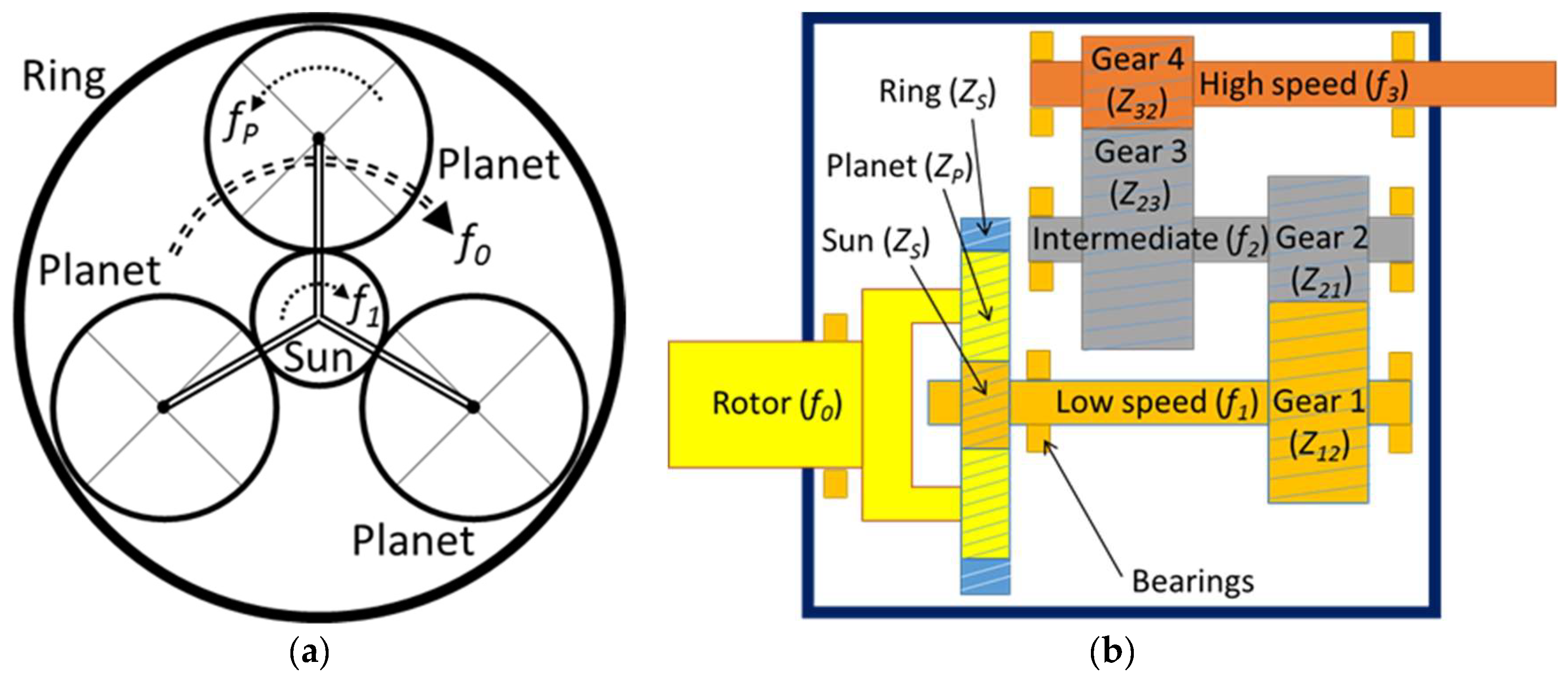
The drive train kinematics must first be determined to identify the basic mechanical vibrations in a rotor-dynamic system, which include shaft imbalance and gear meshing. Outlines of the gearbox configuration for the planetary, intermediate, and high speed stages are provided in
Figure 2. The rotor shaft is the planetary gearing input, while the output is the low speed shaft. The rotor carries the three planet gears that revolve around the sun gear. The planet gears also mesh with an outer ring gear. For the two parallel axis stages, the low speed shaft connects with the intermediate shaft, which in turn connects with the high speed shaft.
The angular rotation frequency of a shaft,
f (Hz), is obtained based on the rotational speed,
N (rpm), while using Equation (1).
The nomenclature used for the rotation frequencies of the shafts and planets relative to the rotor is given in
Table 1. The particular kinematics of the studied gearbox can be described based on the number of gear teeth indicated in
Table 2 and outlined in
Figure 2.
As a result of the gear process, typical vibrations at the gear mesh frequencies are generated in the gearbox. The gear mesh frequencies of the planetary, intermediate, and high speed stages have been named
gmfP,
gmf12, and
gmf23, respectively. The main rotation frequencies and gear mesh frequencies are indicated in
Table 3 as a function of the rotor frequency,
f0. These frequencies can be calculated using Equations (2)–(8).
2.4. Specifications of the Vibration Monitoring System
The wind turbines are built using an integrated system that monitors the main operating parameters, including wind speed, power output, rotating velocity, blade pitch angle, and other factors. The wind speed is measured with ultra-sonic anemometers located on the roof of the nacelle. The data for all the turbines in the wind farm are stored in a SCADA system. Measurements are registered every 10 min. The SCADA data sets are available for analysis.
A CM system based on vibrations is installed in each wind turbine. This system conditions and registers the signals from various accelerometers that are mounted on the drive train components. Two analogue inputs monitor the output power and the generator rotating speed. The system is remotely controlled via TCP-IP (Transmission Control Protocol-Internet Protocol), and the measured data are downloaded at fixed intervals.
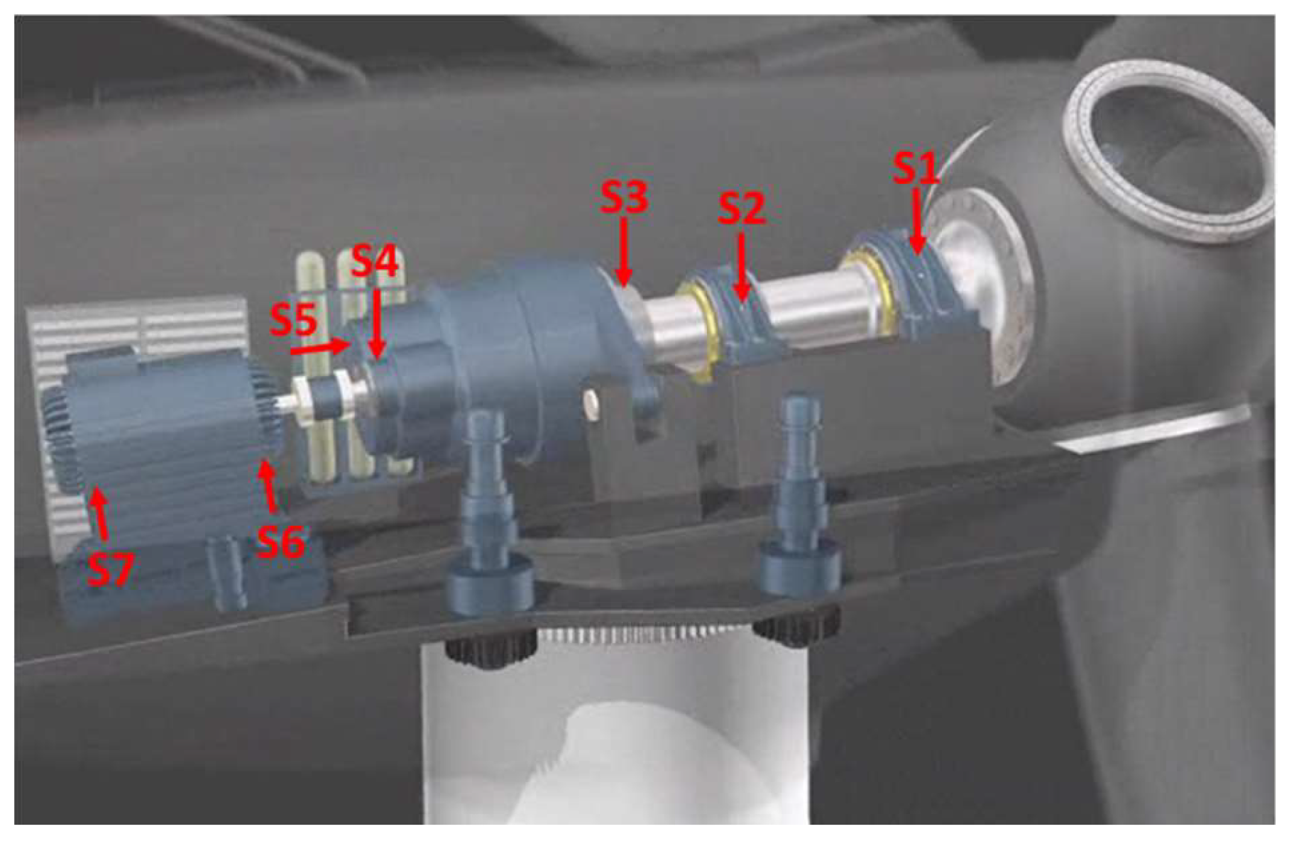
This study focused on seven industrial accelerometers mounted along the drive train components in the positions indicated in
Figure 3. Sensors S1–3 are specifically designed for low speed applications. The remaining sensors are typical for rotating machinery applications. Two sensors are mounted in radial directions on each rotor bearing, three sensors are mounted in radial and axial directions on the gearbox casing, and two sensors are mounted in radial directions on the generator. The positions of the sensors were specifically selected to monitor all shafts, bearings, and gears, as indicated in
Table 4.
2.5. Description of the Measurements
The raw time signals from each sensor are digitized and processed using a digital signal processor (DSP) within the online CM system. The DSP calculates the frequency spectrum. Subsequently, the last measured time signal and the corresponding average frequency spectrum are saved in the data memory.
In addition, the CM system can calculate the frequency content of a vibration signal with user-defined broad band and narrow band characteristic values. The root mean square (RMS) value,
ARMS, is calculated from the frequency spectrum by adding the squares of the amplitudes of
N values over a defined frequency range between
f1 and
f2 and then taking the square root of this value, as indicated in Equation (9).
The CM system processes different measurements depending on the input signals. In our case, the baseband of the calculated frequency spectrum has been selected based on the major monitored frequencies, which are dependent on the corresponding shaft rotation speeds, as indicated in
Table 1. Consequently, the adequate sampling frequency,
fs, the cut-off frequency,
fcutoff, the resulting frequency resolution, ∆
f, and the reference shaft frequency have been set for each measurement, as indicated in
Table 5.
Measurements in the seven WTs were conducted for a continuous period of six months. Therefore, more than 12,000 characteristic values and 150 spectra are available for each unit.
3. Data Validation
To guarantee that the investigated wind turbines were not affected by malfunctions during the study period, the steady-state power output curves from the SCADA data set were compared with those that were provided by the manufacturer following the procedure detailed in Escaler and Mebarki [
18]. The results of this comparison verified that the seven WTs were presumably operating correctly and under optimal conditions.
Because the CM system only registers the power output and the speed of rotation at the moment of the vibration measurement, the 10 min average wind speed SCADA data have been used to estimate the corresponding wind speed at the instant of the measurement. The timestamps that are contained in both databases have been used to interpolate the SCADA values.
The validity of the interpolated values of wind speed, as representatives of the instantaneous values at the moment of the vibration measurement, was verified prior to their use. This verification is necessary given the unsteady nature of the wind. Wind gusts and wind turbulence are among the major causes of fluctuations in operating conditions and vibrations.
To identify and remove the vibration values that were not associated with steady wind conditions, the power output was plotted as a function of the estimated instantaneous wind speeds and compared with the upper and lower percentiles (5 to 95%) of the mean power curves, which were previously calculated from the SCADA data set. Then, only the vibration measurements associated with the output power levels plotted between the estimated percentiles were used for wind speeds from 4 to 12 m/s, meanwhile at wind speeds greater than 12 m/s, only those measurements with output power values ranging from 1900 to 2100 kW were used, as described in Escaler and Toufik [
18].
4. Results
To identify the main frequency components of a vibration spectrum for a given sensor measurement (
Table 5), the spectrum frequency axis,
f, has been divided by the corresponding instantaneous rotation frequency,
fi, of the reference shaft (
i = 0, 1, 2, or 3) at the time of the measurement. From the spectra of all WTs with normalized frequency axes, the central amplitude value, or the 50th percentile, has been plotted in black combined with a grey area denoting the values that lie between the 25th and 75th percentiles. The median was used to compute average amplitude values, because it is not appreciably influenced by outlier values and it is generally more robust than mean-based estimates. Thus, the 50th percentile spectra and the percentiles obtained for each measurement are plotted in
Figure 4,
Figure 5,
Figure 6,
Figure 7 and
Figure 8 and are discussed in the following sections.
4.1. Rotor Vibration Signature Analysis
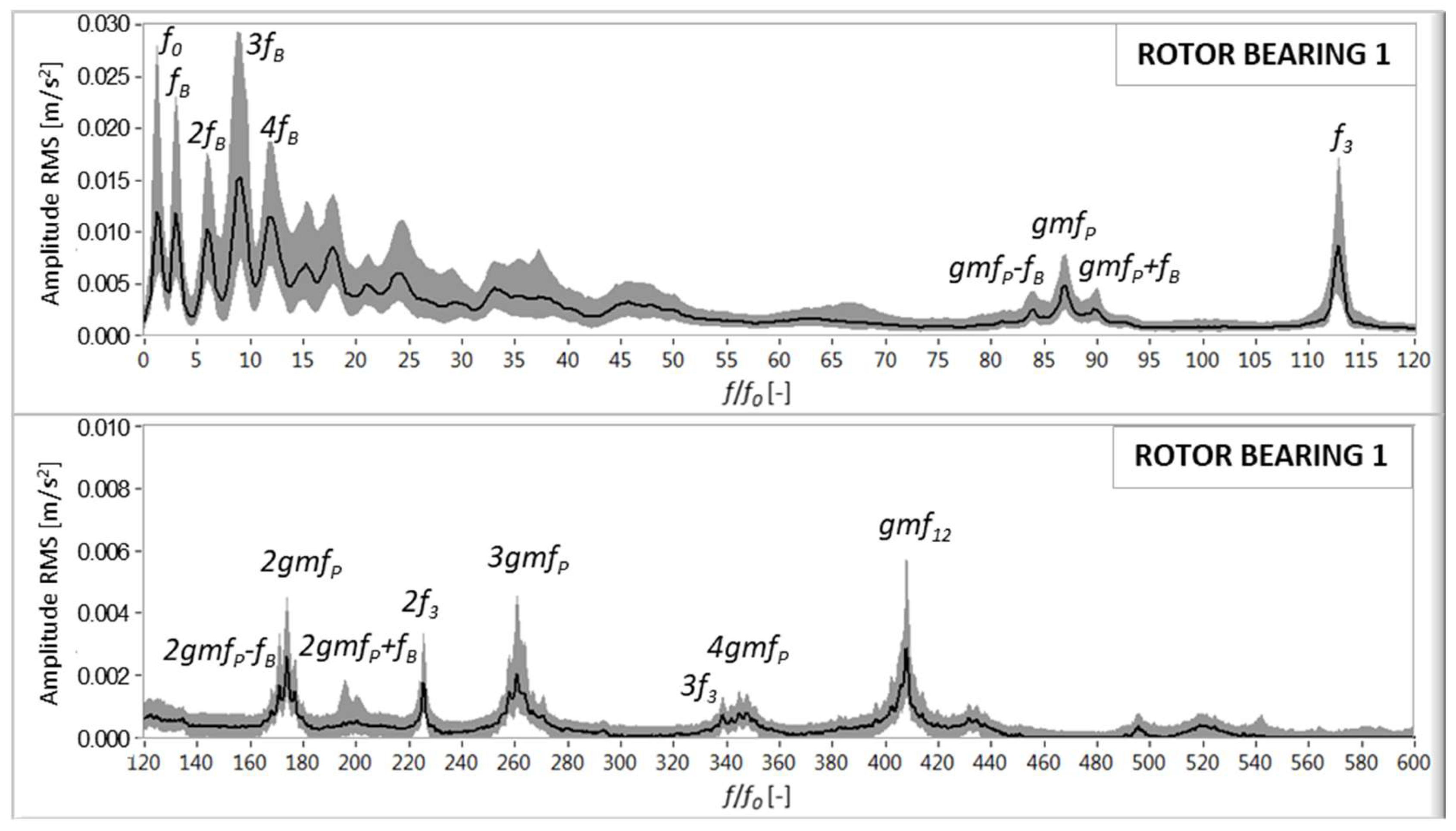
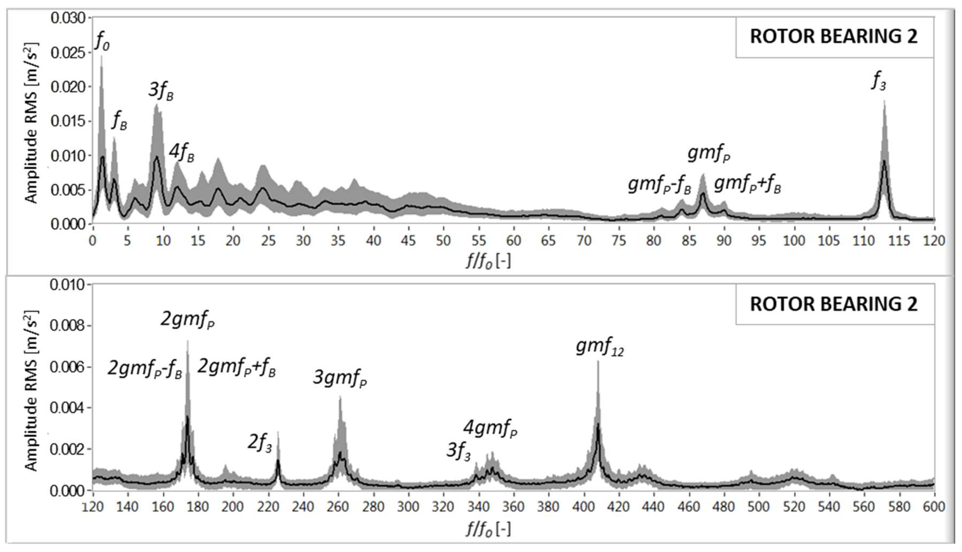
The vibratory signatures of the vibrations measured on both rotor bearings are plotted in
Figure 4 and
Figure 5, reaching up to 600 times
f0. In both bearings, a frequency peak at 3
f0, which is called the blade passing frequency,
fB, is clearly observed. This vibration is due to tower dam excitation, which occurs once per revolution due to the short-term collapse of the aerodynamic forces at the blade when the blade approaches the tower.
In the front rotor bearing closer to the hub (
Figure 4), the low frequency content is dominated by
f0,
fB, and several harmonics of
fB. In the high frequency range,
f3 and 2
f3 are also present, corresponding to the generator shaft. Finally, the gear mesh frequency of the planets,
fP, and its harmonics appear with sidebands at
fB, as does the gear mesh of the low speed-intermediate stage
gmf12.
In the rear rotor bearing closer to the gearbox (
Figure 5), the vibration peaks and amplitudes are similar to those that were observed in the front bearing. Nevertheless, the harmonic content of
fB decreases, as only 2
fB is present.
4.2. Gearbox Vibration Signature Analysis
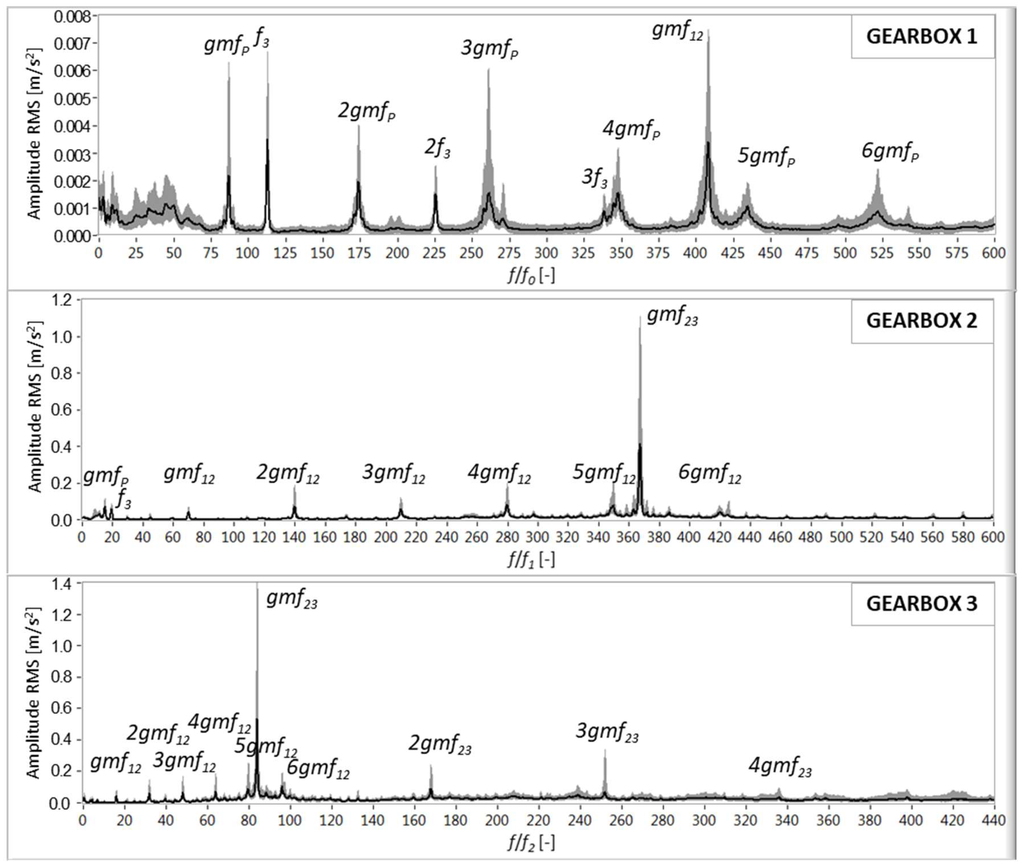
The vibratory signatures of the vibrations that were measured in the gearbox casing are plotted in
Figure 6. In the vertical position close to the planetary gear (top graph), the main peaks are associated with
gmfP (up to its 6th harmonic),
f3, 2
f3, and
gmf12. In general, the frequency is analogous to those measured in the rotor bearings.
With a baseband up to 600 times f1, the highest peak in the vertical position close to the intermediate shaft bearing (middle graph) corresponds to the gear mesh frequency gmf23 of the intermediate-high speed stage. At lower levels, peaks that are associated with gmf12 (up to its 6th harmonic), gmfP, and f3 can also be found.
With a baseband up to 440 times f2, the highest peaks in the axial position close to the generator shaft (bottom graph) are again gmf23, 2gmf23, and 3gmf23. The gmf12 and its harmonics up to 6gmf12 are also measured.
4.3. Generator Vibration Signature Analysis
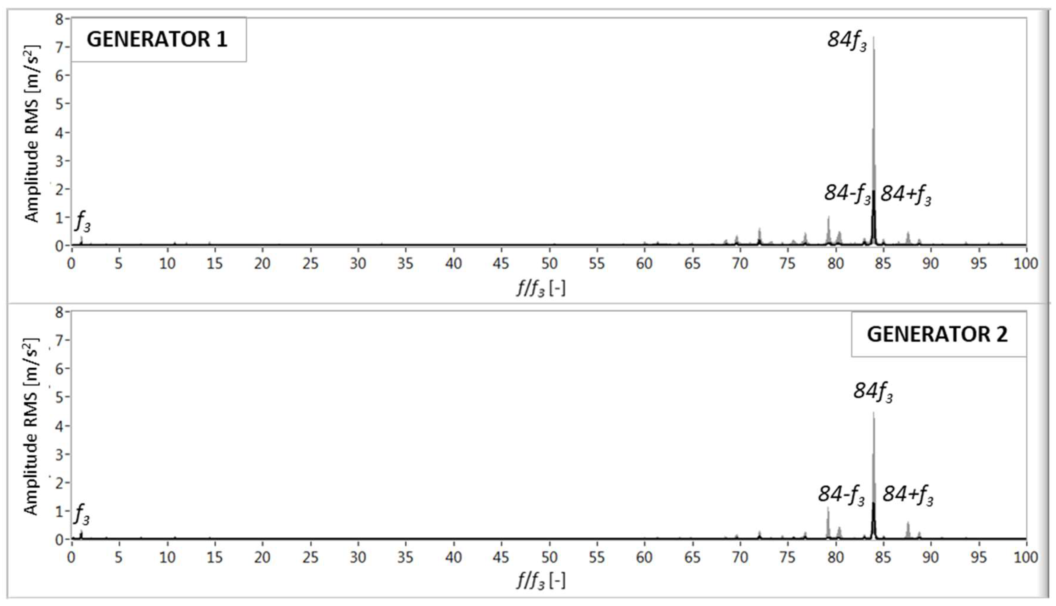
The vibratory signatures of the vibrations measured on the generator supports are plotted in
Figure 7. In both the front and rear positions relative to the gearbox, the most remarkable peaks are the high speed shaft frequency
f3 and a harmonic component at 84 times
f3 with sidebands at
f3. The latter is not a gear mesh frequency; therefore, it may be provoked by electromagnetic excitation. Peaks can be observed around 84
f3; however, these peaks cannot be attributed to a known kinematic condition that is associated with the gearbox or shaft.
4.4. Tower/Nacelle Vibration Signature Analysis
The vibratory signature of the low frequency vibrations measured on the gearbox casing close to the generator in the axial direction are plotted in
Figure 8, reaching up to 15 times
f0. This measurement quantifies the tower/nacelle vibrations, as suggested by Escaler and Mebarki [
18]. The predominant peak is
fB; however, individual values exhibit significant separation throughout the spectrum. The other peaks correspond to
f0, 2
fB, and 3
fB.
5. Discussion
5.1. Comparison of Mean Vibration Amplitudes and Deviations
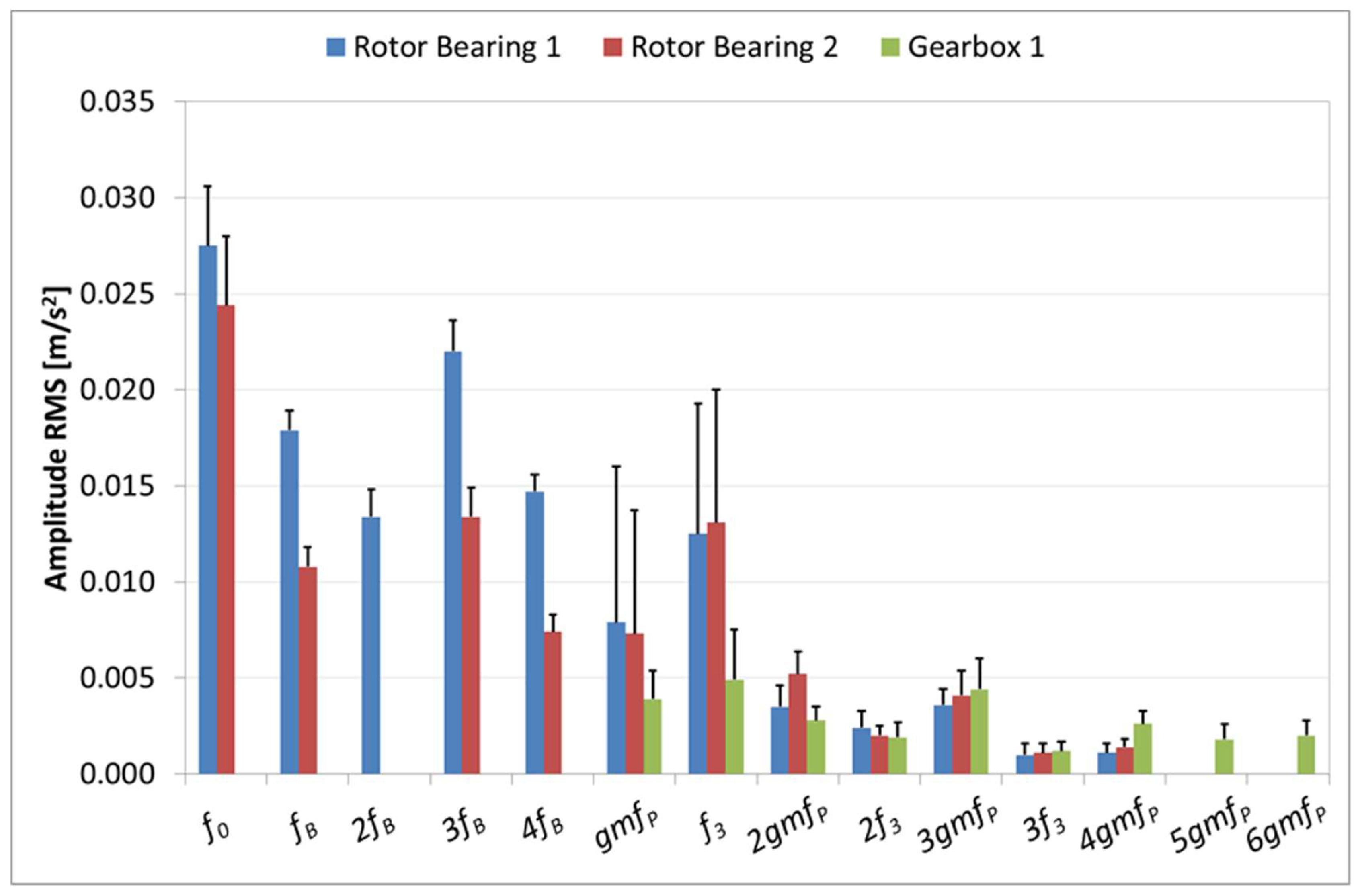
The widths of amplitude values between the 25th and the 75th percentiles were significant for most of the frequency peaks that were identified in the vibration signatures of all the measurements. This result indicates significant spread or variability exists in the spectral values collected in this study. Therefore, dispersion was quantified for the most relevant peaks, while the mean spectrum and its standard deviation were calculated from all the WT measurements. The corresponding results are plotted in
Figure 9 and
Figure 10, with bars showing the average values and vertical lines showing the positive deviations.
Similar vibration peaks and levels are measured in both rotor bearings, although more harmonics that are associated with the blade passing frequency are present in the front bearing close to the hub, as shown in
Figure 9. The generator frequency and the planetary gear frequency were also measured and their amplitudes exhibit significant standard deviations. The gearbox 1 measurement, which was located on the low speed side of the drive train, detected
f3 and
gmfP, but at lower amplitudes than on the rotor bearings. This gearbox measurement detects up to the 6th harmonic of
gmfP, as it has a larger frequency band than the other two rotor bearing measurements. In general, the maximum vibration levels are dominated by
f0,
fB, and the harmonics of
fB in the rotor bearing vibrations.
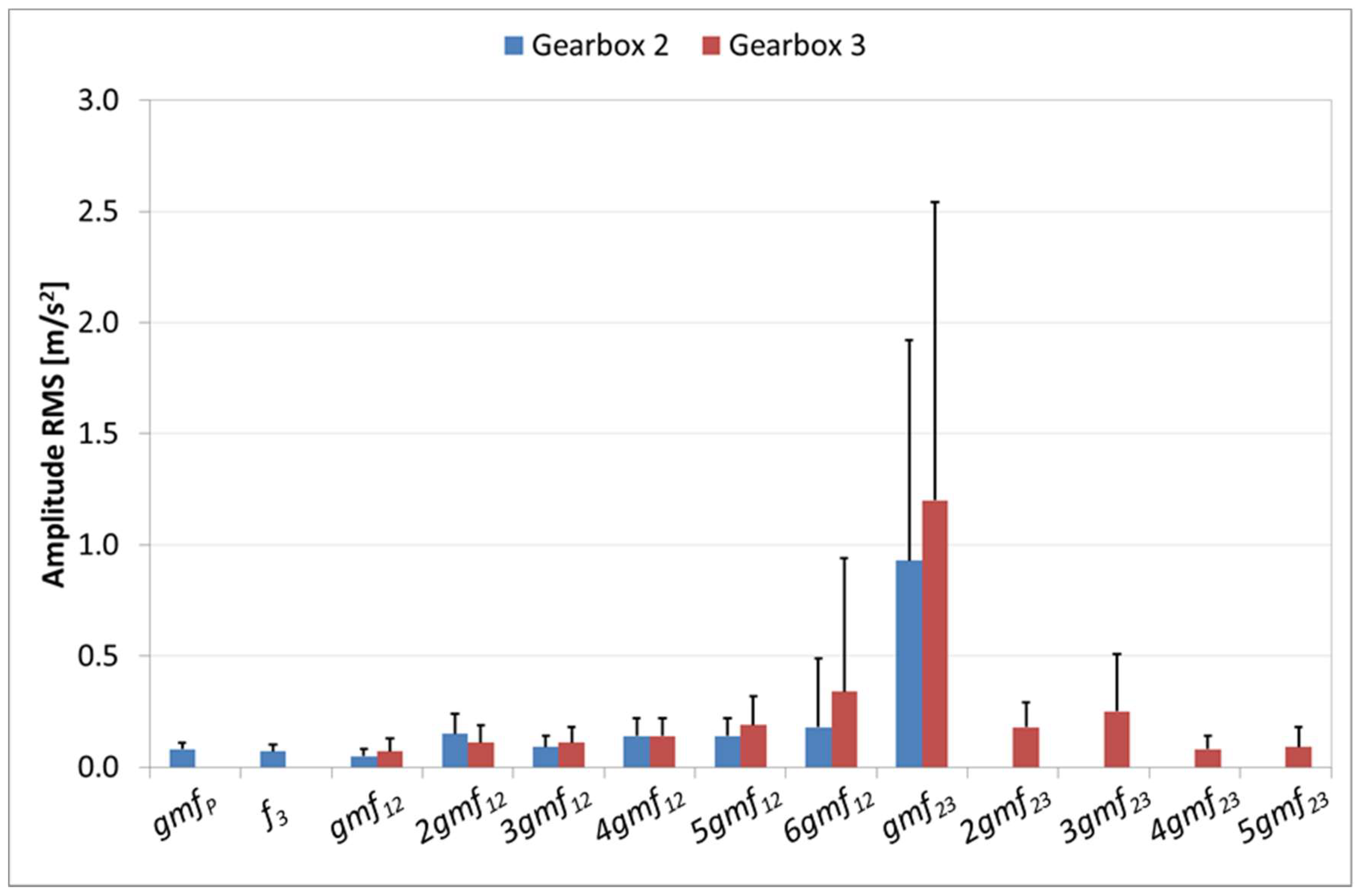
The two measurements gearboxes 2 and 3, corresponding to sensors S4 and S5 located on the high speed side of the gearbox, detect the gear mesh frequencies of the intermediate and high speed stages, as shown in
Figure 10. The baseband selected for the gearbox 2 measurement (vertical orientation) encompasses
gmf23 but not the associated harmonics. This measurement also detects
gmfP and
f3. The larger frequency band of the gearbox 3 measurement (axial orientation) detects the harmonic contents of
gmf23 and
gmf12. Note that the mean amplitudes of the peaks are similar in both gearbox measurements. Among all of the peaks, the highest amplitudes are observed for
gmf23. For this meshing frequency, the standard deviation of the amplitudes is also significant.
Significant standard deviation values have also been found for fB in the gearbox 4 measurement, which monitors the tower vibrations, and for 84f3 in both generator measurements, which monitor the electromagnetic vibrations.
5.2. Wind Speed Amplitude Dependency
To investigate the spread of individual amplitude levels observed in the majority of the frequency peaks, the calculated characteristic values (based on Equation (9)) of the measurement basebands (
Table 5) have been analyzed as a function of wind speed. These values represent the broadband RMS amplitudes obtained by adding all the individual frequencies present in the spectrum. In this case, data from three of the seven WTs is used, because they utilize exactly the same gearbox model. The preliminary data validation that is discussed in
Section 3 was also applied.
The vibration amplitudes for one measurement in the rotor bearing, one in the gearbox and one in the generator are plotted in
Figure 11. The amplitudes are clearly dependent on the operational conditions, as highlighted in all graphs. Moreover, it is confirmed that the data trend is dependent on the component being measured.
For example, in the front rotor bearing, the data points exhibit a linear trend with a positive constant slope. In the high-speed side of the gearbox casing and in an axial direction, the data trend is not linear. A rapid amplitude increase is observed at low wind speeds up to the rated wind speed, peaking at approximately 7 m/s. Generally, the shape of the data resembles the output power curve of the turbine. From the rated speed to the cut-out speed, the data amplitude is relatively constant. Finally, in the rear side of the generator, the data trend is also similar to the turbine power curve; however, the generator data have a different slope than the gearbox data.
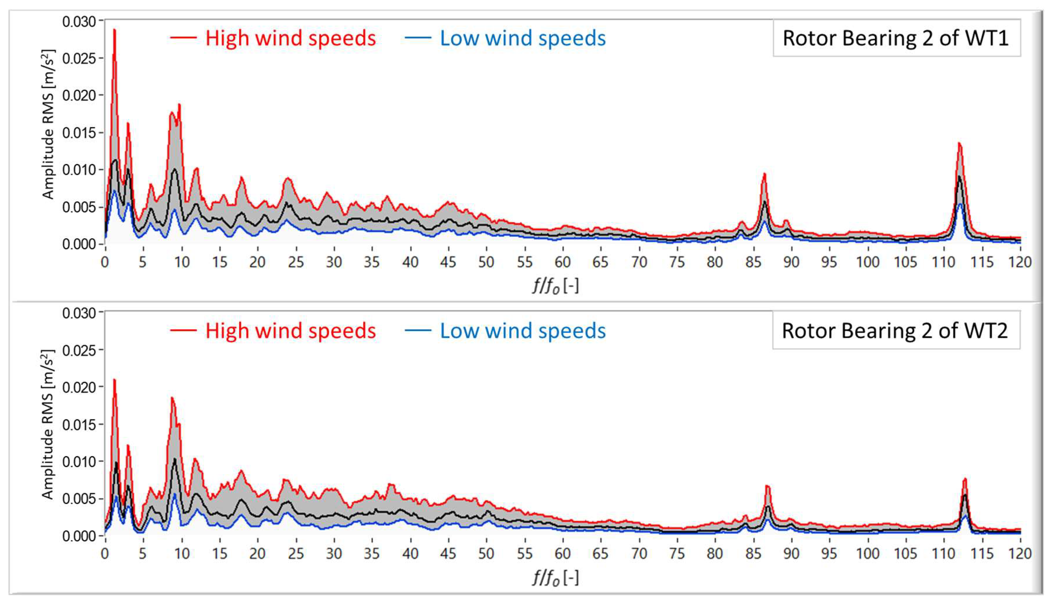
In
Figure 12, it is observed that the median and the percentiles of vibrations that were measured on the rear rotor bearing of two WTs are very similar. In fact, it is confirmed that the same happens for the rest of WTs and measurements. Consequently, it can be assumed that the large variability found is mainly due to the operating conditions. At low wind speeds, the spectra have low amplitudes and they are below the 25th percentile values. At high wind speeds, the spectra have high amplitudes above the 75th percentile values. Therefore, high reference values do not indicate faults, they just show the vibration response to stronger loads on the drive train components.
The information provided by these plots highlights the difficulty of protecting variable-speed and variable-pitch machines while using the CM system, because the amplitudes of the vibrations strongly depend on the operation conditions. Nevertheless, this study confirms the feasibility of obtaining statistical information that represents the normal range of vibration levels for a set of similar WTs. With these vibration limits, a more precise and reliable assessment of the machine vibration response can be achieved.
6. Fault Detection Case
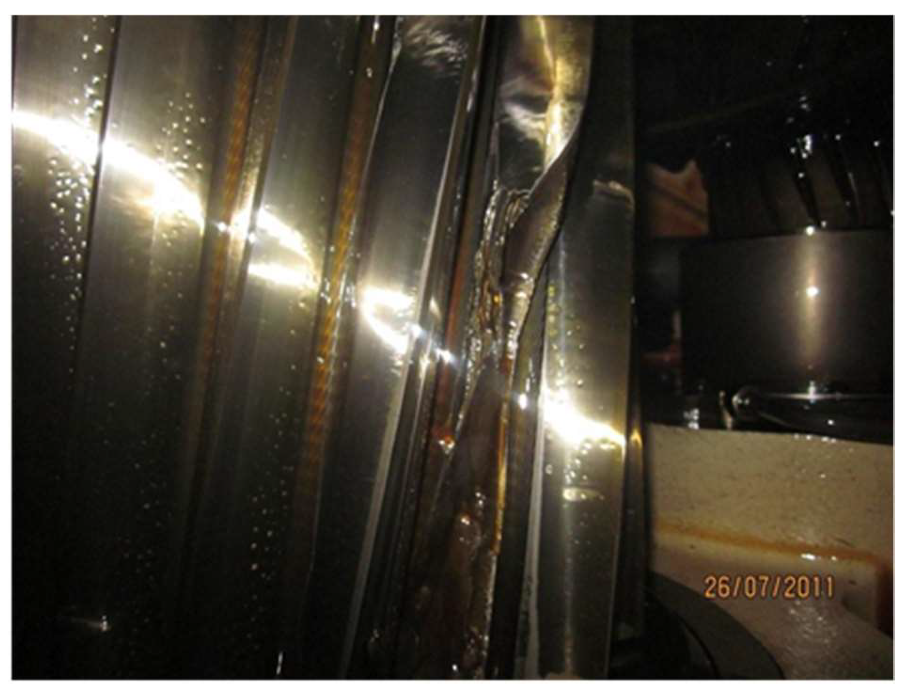
A fault on the drive train and its symptoms that is based on the vibration signature of these turbines is presented here. The tooth of gear 2 in the intermediate shaft of a wind turbine (see
Figure 2b) was broken. This can be seen in the photograph shown on
Figure 13 taken during inspection. This fault could be predicted and repaired prior to a machine unexpected down time based on the amplitude evolution of the corresponding gear mesh frequency,
gmf12, and its first three harmonics.
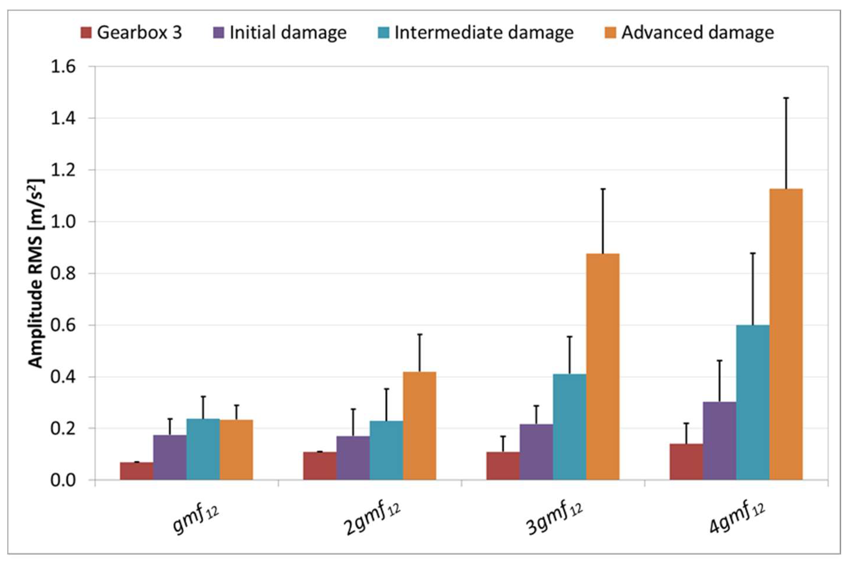
In
Figure 14, the reference mean vibration acceleration RMS values of the gear mesh frequency peaks (
Figure 10) and the corresponding mean values measured in the wind turbine with progressive levels of gearbox damage are compared. The mean values presented in
Figure 14 correspond to different periods of time along the damage evolution. Each value has been calculated from a set of around 300 measurements taken during an interval of four days. It must be noted that, during those days, the wind turbine was operating normally without any restriction.
It can be seen that all the amplitudes of the gear mesh frequency peaks increased simultaneously up to twice the reference levels when the gear damage started to develop. The peaks continued to increase, as the damage developed, reaching their maximum amplitudes for advanced damage. Finally, after repairing the fault, the amplitudes returned to their original levels.
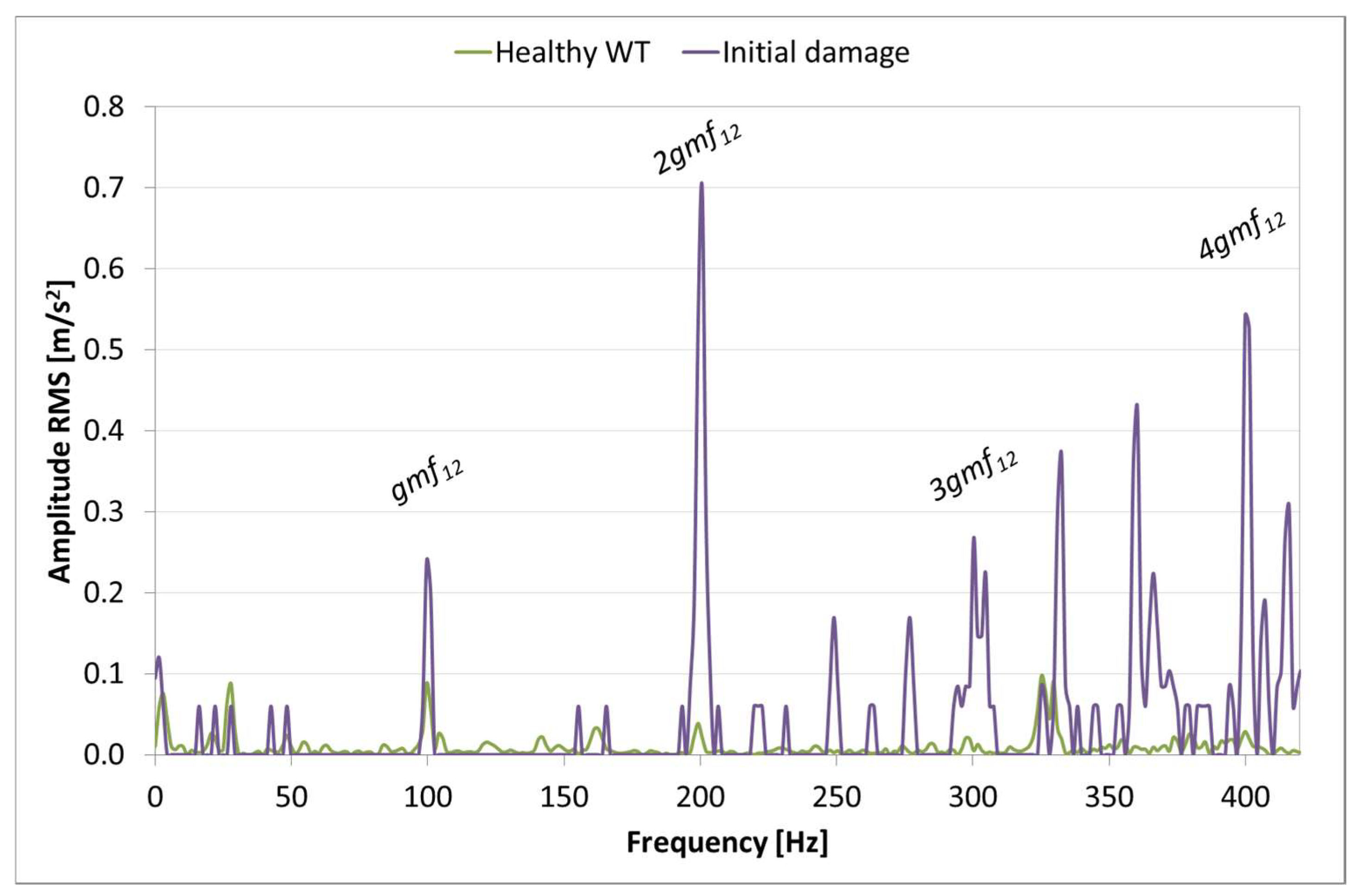
To observe the change of vibratory signature induced by the fault, one spectrum measured at full load during a healthy period of time has been compared with one spectrum that was measured during the initial stages of damage, as shown in
Figure 15. It can be clearly seen that all of the frequency peaks related to the gear meshing suffer a significant amplitude increase. Moreover, additional frequency peaks appear which are sideband modulations.
Therefore, it is demonstrated that knowing a reference vibration signature with a mean value and the possible range of variation due to operating conditions is a valuable tool to monitor changes of the dynamic behavior of the drive train components induced by faults. To confirm the abnormal behavior, the evolution with time of the anomalous levels must be tracked. As the damage develops, these values will rise and a machine inspection should be carried out urgently before the failure occurs. Nevertheless, an additional study of the symptoms that are associated to other types of damages and affecting other components is required to confirm the current findings and to evaluate more precisely their sensitivity.
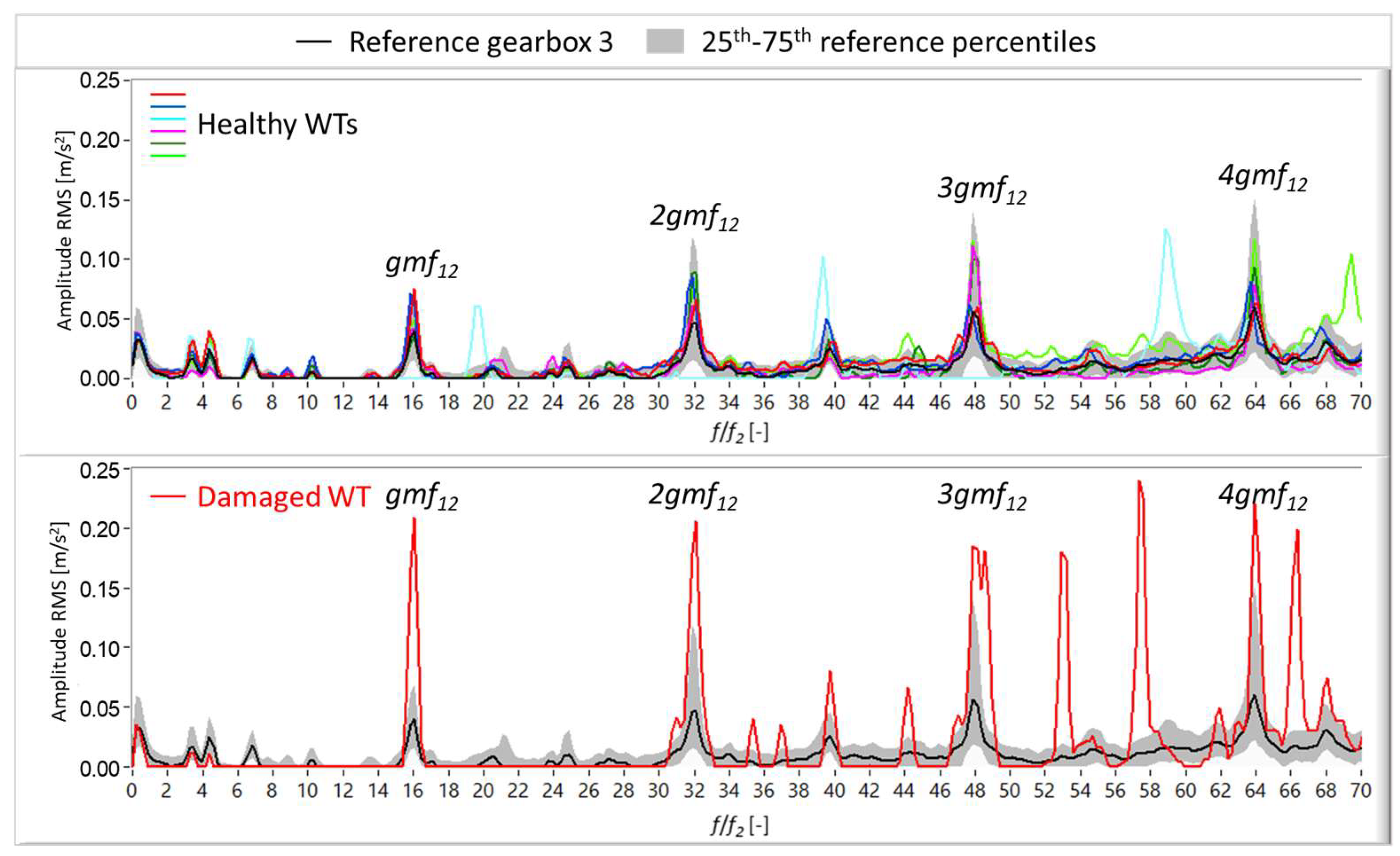
The variability of the reference vibration signature does not prevent detection of the initial stages of the damage because, as already explained, it mainly takes into account the effect of the wind loads on the measured vibration levels. The median spectra of each healthy WT are within the 25th and 75th percentiles (grey area) of the corresponding reference signature, as shown at the top of
Figure 16. Meanwhile, the median spectrum of the damaged WT is clearly above the 75th percentile level, as shown at the bottom of
Figure 16, which demonstrates the sensitivity of the presented reference values to this particular gear damage.
7. Conclusions
The mean vibration signature (baseline frequency spectrum) of a group of healthy WTs was obtained using accelerometers that were mounted on the rotor bearings, gearbox casing, and generator supports. From these measurements, the frequency peaks that are associated with the various excitations that originated at the WT components were identified. These frequencies are due to mechanical, aerodynamic and electromagnetic forces. These results can be used as reference spectra for assessing normal machine conditions and to set alarm levels. If faults occur or wear is enhanced, new defect frequencies will appear and/or unexpected changes of the normal frequencies present on the reference spectra of the affected component will be observed. The recognition of these changes is essential for the early detection of faults or threats. Moreover, a significant impact of the wind speed on the vibration amplitudes has been observed; this impact also depends on the component being measured. Therefore, this behavior must also be taken into account when defining individual reference values and predicting the severity of damage.
