Article

Study on Surface Roughness of Gcr15 Machined by Micro-Texture PCBN Tools

College of Machinery and Vehicle Engineering, Changchun University, Changchun 130022, China
*
Author to whom correspondence should be addressed.
Machines 2018, 6(3), 42; https://doi.org/10.3390/machines6030042
Submission received: 5 September 2018 / Revised: 12 September 2018 / Accepted: 13 September 2018 / Published: 17 September 2018

Abstract

:
This paper applies micro textures to the rake face of PCBN (Polycrystalline Cubic Boron Nitride) tools, including three types of micro textures that are microgroove textures vertical to the cutting edge, microgroove textures parallel to the cutting edge, and microhole textures. In this paper, the effects of different cutting speeds on the surface quality of hardened bearing steel GCr15 by dry turning with non-texture PCBN tools and micro-texture PCBN tools are studied, and the surface roughness values obtained by different micro textures were compared and analyzed. The results showed that, compared to that of non-texture tools, the influence degree of the micro-texture tools on the machined surface roughness was different. The microhole texture and vertical microgroove texture were able to effectively reduce the surface roughness of the workpiece, and microhole texture had the best effective influence on surface roughness, but the parallel microgroove texture increased surface roughness. The influence of cutting speeds on surface roughness was different due to different types of micro textures. The influence of micro textures on surface roughness has huge potential for tool applications.

1. Introduction

Surface quality, as one of the most important indexes for measuring cutting performance, has always been the focus of cutting research. Scholars have continuously studied and analyzed the factors affecting surface quality, such as the plastic deformation of the workpiece, the geometric shape of the tool, the cutting parameters, and the cooling modes, and combined with the roughness prediction models, the best processing scheme is successfully summed up to get good surface quality.
In the study of aluminum alloy surface roughness tests, Wan et al. concluded that spindle speed was the most important factor affecting surface roughness when milling aluminum alloy 6061 at a high speed, and the milling parameters for obtaining the best surface quality were obtained [1]. Joshua et al. found that the feed had the greatest influence on surface roughness, followed by the spindle speed, and the cutting depth had the smallest effect on surface roughness during end milling of aluminum 6061 under minimum quantity lubrication. At the same time, the combination of feed and spindle speed was more favorable to obtaining good surface quality [2]. The influence of milling speed on surface roughness was studied by Bonţiu et al. when milling aluminum alloy 7136 [3]. Luo et al. found that passivated PCD (polycrystalline diamond) tools in turning aluminum alloy 1060 could reduce surface roughness [4]. Additionally, in the study of the surface roughness of titanium alloy, Wang et al. showed that applying ultrasonic torsional vibration could obviously reduce the surface roughness of titanium alloy TC11, and concluded that large amplitude and low milling speed were beneficial to reducing surface roughness [5]. In the test of milling titanium alloy Ti6Al4V, Li et al. found that the roughness of a milled surface increased with the increase of milling speed, feed per tooth, milling width, and milling depth [6]. Oliaei et al. investigated the influence of built-up edge formation on surface roughness through microscale orthogonal cutting tests on titanium alloy Ti6Al4V, and found that the influence of built-up edge on surface roughness varied, depending on the cutting speed and uncut chip thickness [7]. Du et al. studied the influence of the rake angle, the clearance angle, and the helix angle of the carbide milling cutter on the surface integrity of titanium alloy TB17, and concluded that surface roughness increased when increasing the rake angle, the surface roughness reduced when increasing the clearance angle, and surface roughness showed the trend of first decreasing and then increasing with the increase of the helix angle [8].
In the study of the roughness of the turning surface, Wang et al. used the regression analysis method and established the LS-SVM forecast model in the precision turning mirror surface roughness test; the results showed that the effects of tool nose radius and feed were more significant than those of depth of cut on surface roughness [9]. The surface roughness of the precision turning optical lens was studied using response surface methodology. Li et al. concluded that the tool nose radius had the greatest influence on surface roughness, followed by the feed and the cutting depth [10]. Luo concluded that the most significant effect on surface roughness came from the feed speed; the cutting speed was second, but the cutting depth had no direct effect on the surface roughness while turning high strength steel 58SiMn [11]. Khatri et al. attempted to improve the surface finish of diamond turned silicon with magneto-rheological finishing, and concluded that a smaller gap, high wheel speed, and high current result in minimum surface roughness [12]. In the study of the roughness of hardened steel, Suresh et al. made experiments based on the central composite design (CCD) concept of response surface methodology (RSM). During turning of hardened steel with coated ceramic tool, the experimental results showed that the feed had the greatest influence on surface roughness, followed by the cutting speed, and the cutting depth had the least influence [13]. Liu et al. pointed out that surface roughness would rise along with the speed of grinding wheel, and workpiece increased within a certain range when grinding hardened steel GCr15 [14]. Krolczyk et al. researched the surface morphology of duplex stainless steel using the method Power Spectral Density for dry and MQL/MQCL (Minimum Quantity Lubrication) turning process [15], Krolczyk concluded in the following study that the application of the MQCL method can lead to the reduction of 3D surface roughness parameters compared to values reached after dry machining, and surfaces machined with the use of the MQCL technique can be characterized by a high wear resistance [16]. Liu et al. proposed a ground surface roughness measurement method to address current problems in the use of machine vision technology to measure roughness, and the results demonstrated that the surface roughness measurement method had relatively high accuracy and a relatively wide measurement range [17]. Chen et al. demonstrated a Nested-ANN (Artificial Neural Network) model predicting surface roughness, and pointed out that the nested-ANN uses less input variables to obtain superior prediction accuracy than other models [18].
In view of the current research status and research methods of surface roughness in literature, this paper uses the micro-texture method, that is, the micro dimension textures processing on the rake face of tools, and studies the influence of micro textures on the surface roughness of the workpiece.

2. Type of Micro Textures and Test Scheme

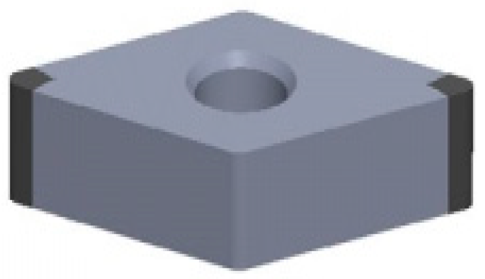
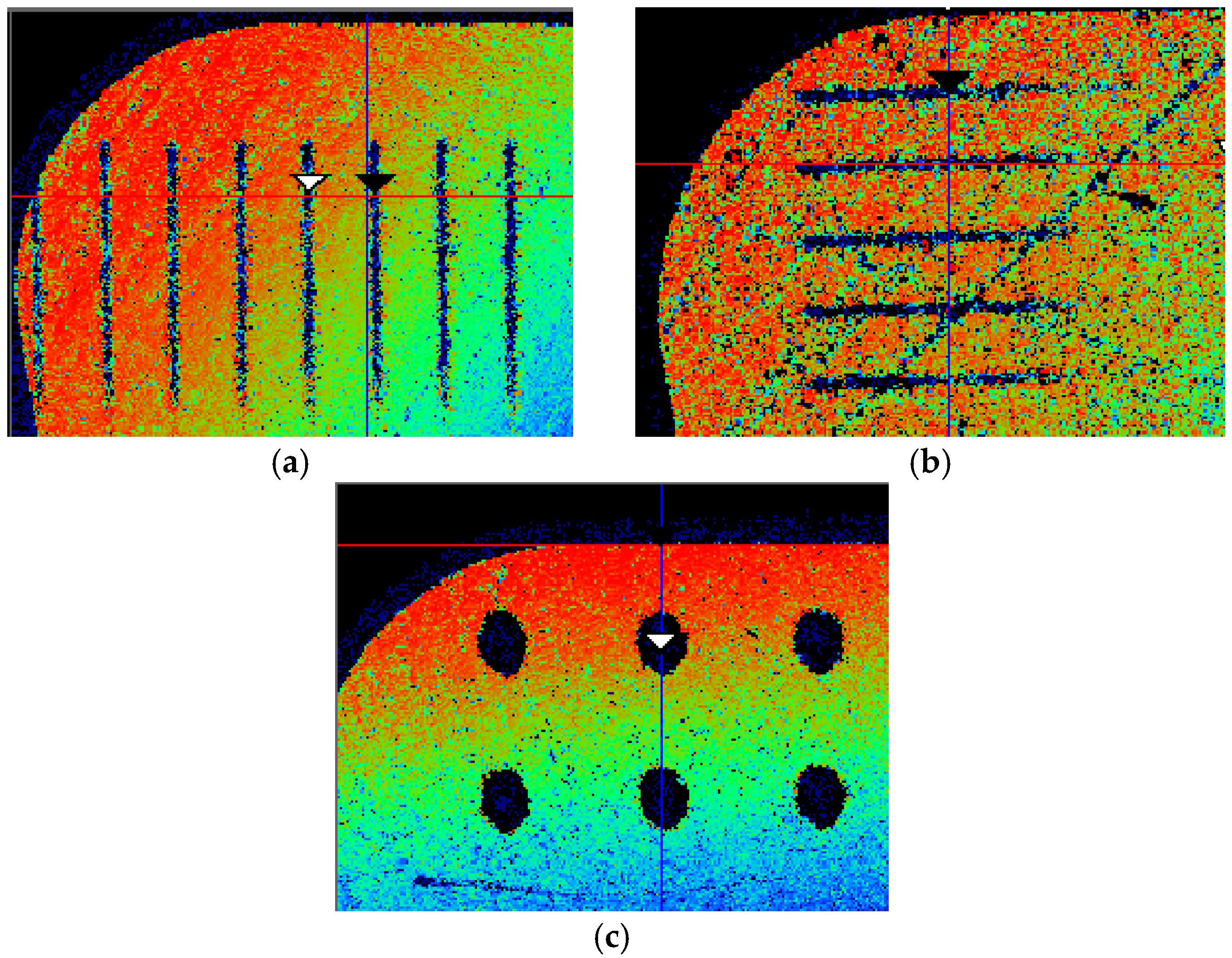
2.1. Type of Micro Textures

In order to study the actual situation of cutting parts of micro texture cutting tools, three micro textures were processed on the rake face of PCBN tools with the Fiber Laser Marking machine (FLY-M10F) fully enclosed rotary optical fiber laser marking machine. The types of micro textures included 30 μm microgrooves perpendicular to the cutting edge, 40 μm microgrooves parallel to the cutting edge, and micro holes of 120 μm in diameter. Table 1 is the micro-texture size. As shown in Figure 1, the blade is the CNGA120408 PCBN tool. The WYKO N7910 optical profiler was used to detect the three-dimensional texture of the micro textures, as shown in Figure 2: Surface morphology of micro-texture tools.

2.2. Test Parameters and Solutions

In this cutting test, the CA6140 lathe was used for turning hardened steel GCr15 with hardness of 58 HRC. Figure 3 is the GCr15 workpiece. The rake angle of the tool was −6°, the clearance angle was 6°, the feed was 0.1 mm/r, and the cutting depth was 0.2 mm. The specific plan was as follows:
(1).
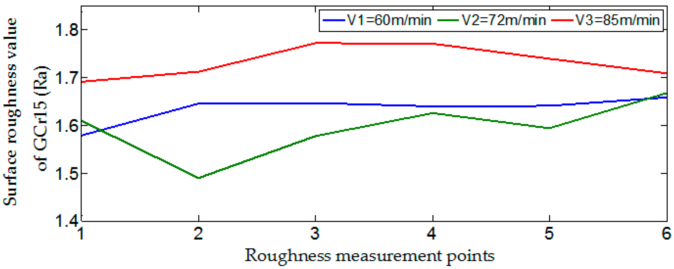
Dry cutting of hardened steel GCr15 test was carried out using normal PCBN tools (normal PCBN tools: Non-micro texture PCBN tools) at different cutting speeds of v1 = 60 m/min, v2 = 72 m/min, v3 = 85 m/min;
(2).
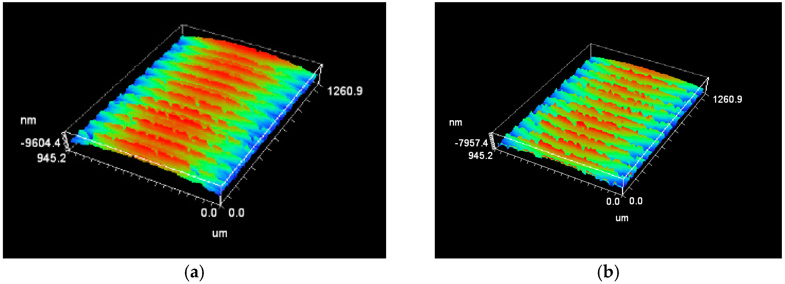
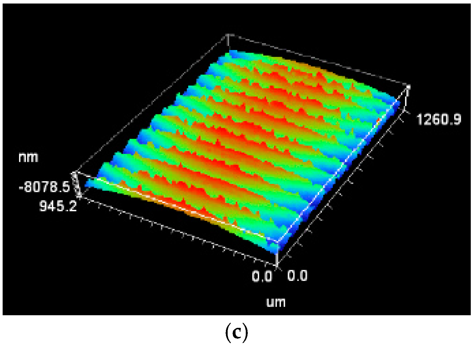
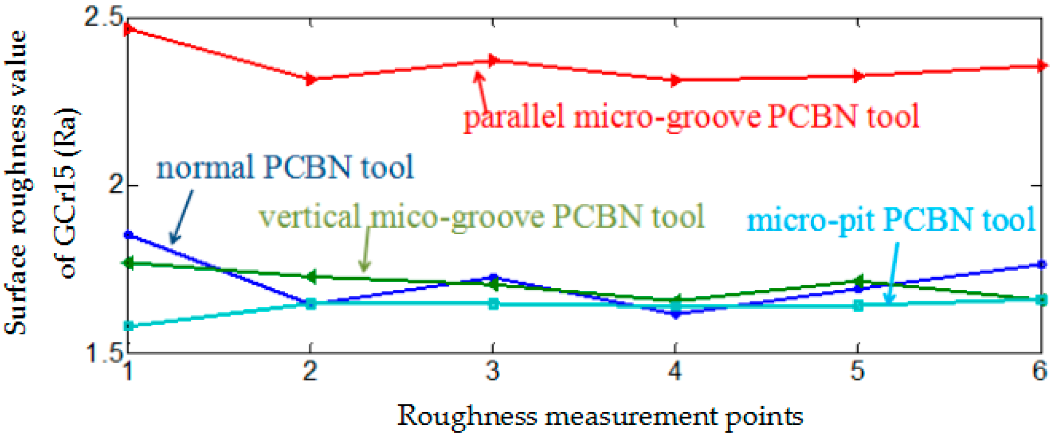
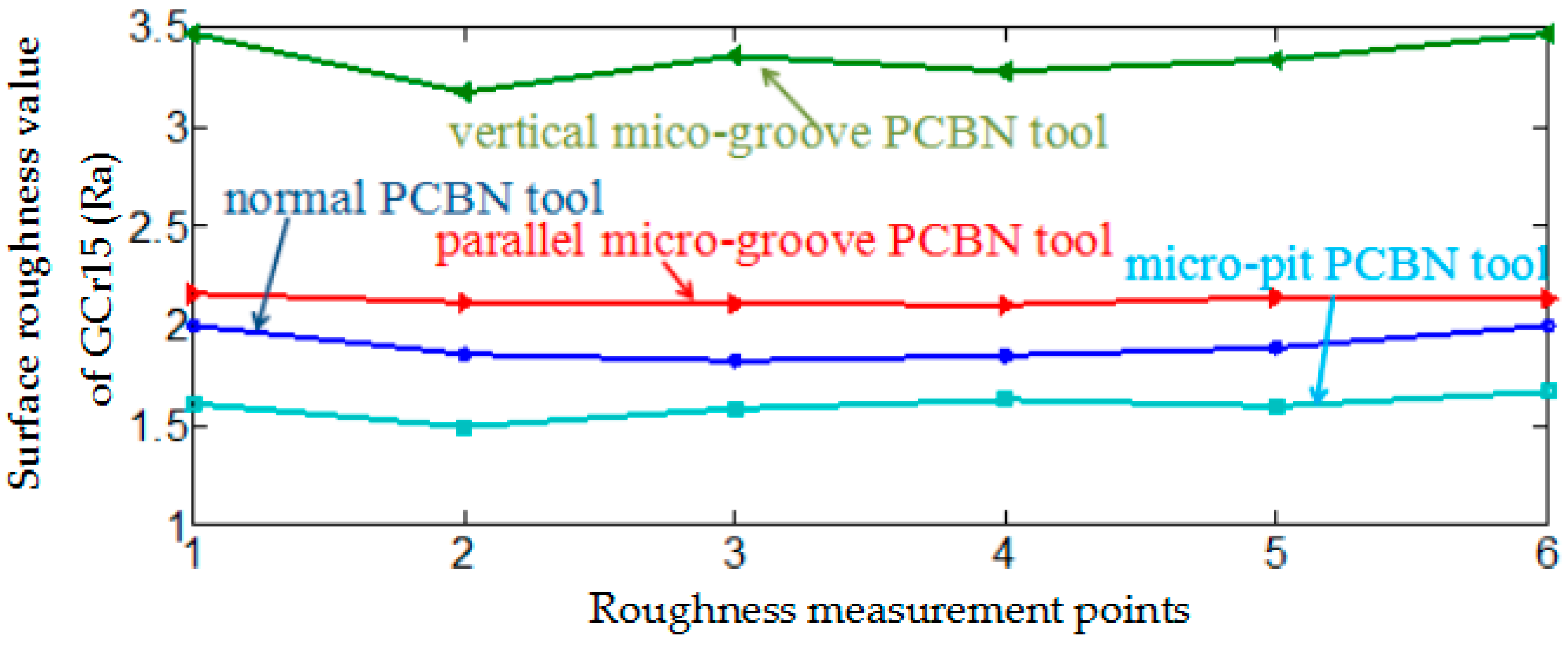
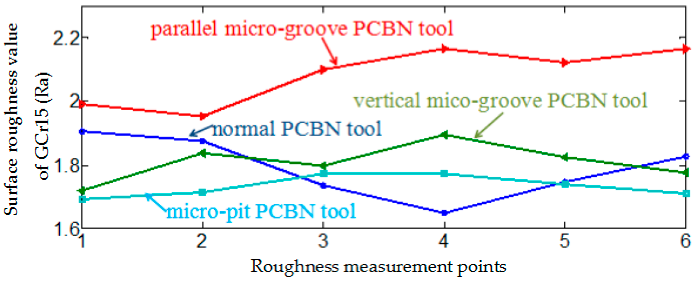
The cutting tests of micro-texture PCBN tools (vertical microgroove PCBN tools, parallel microgroove PCBN tools, and microhole PCBN tools) were carried out respectively, and the surface roughness of the workpiece was measured with a WYKO N7910 optical profiler, all of which were compared to the test of normal PCBN tools.

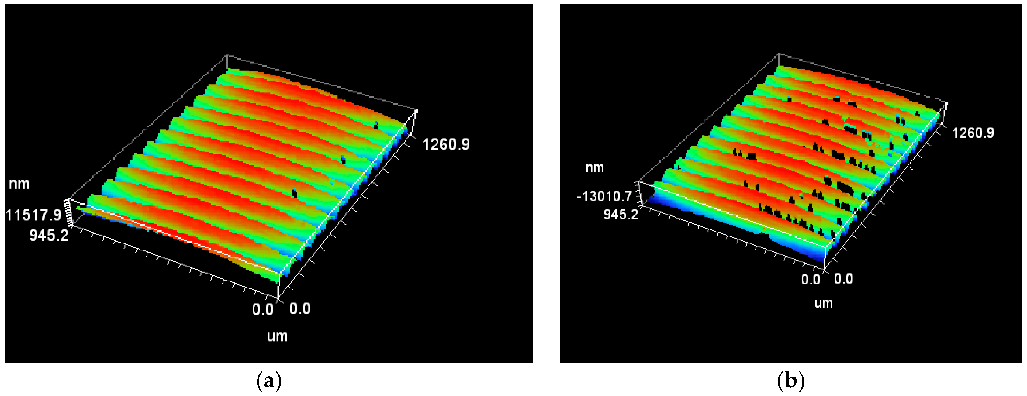
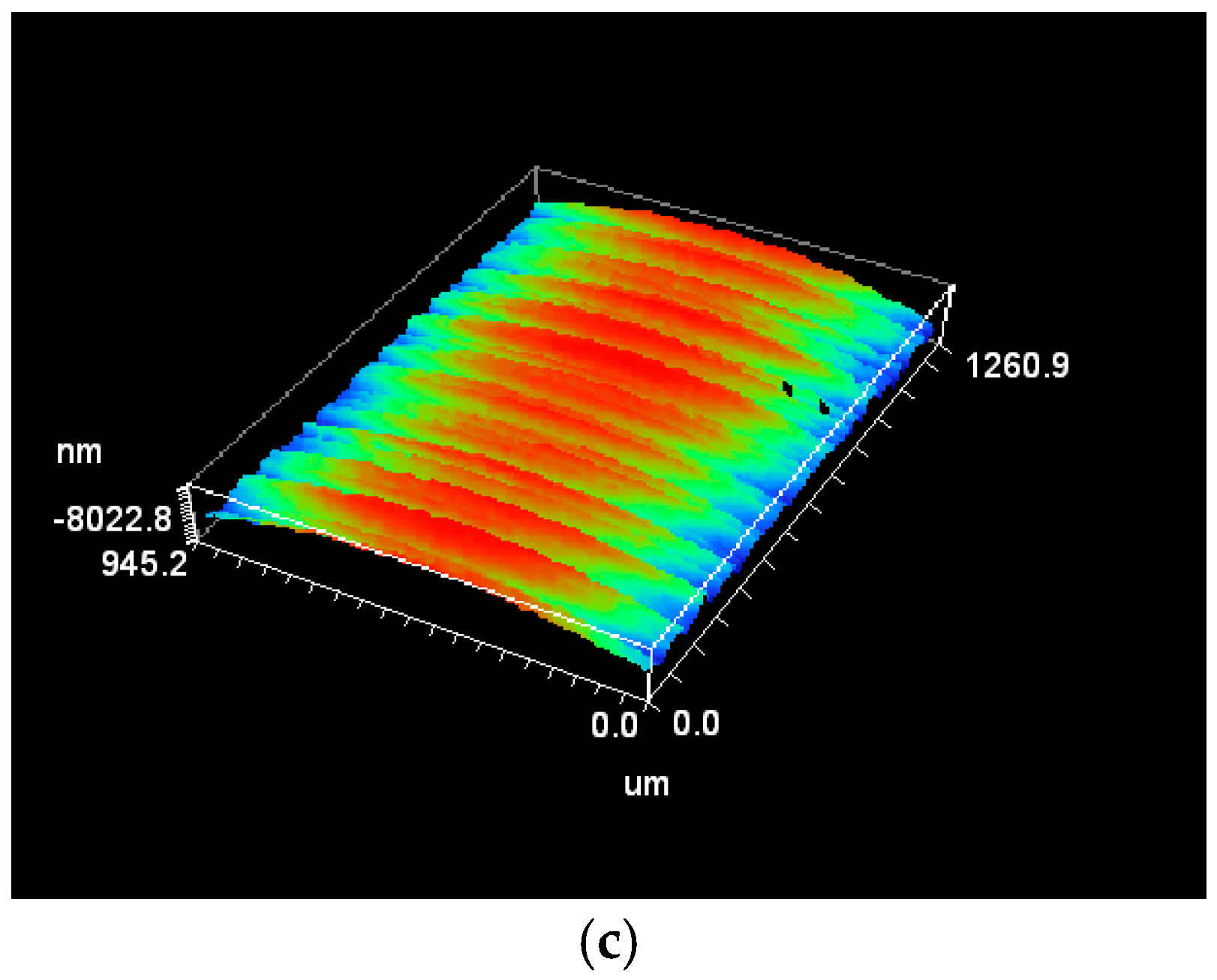
3. Analysis of Test Results

According to the test scheme, the cutting tests were carried out. The surface roughness data of GCr15 were measured and analyzed. The effect of micro textures on surface roughness was obtained.

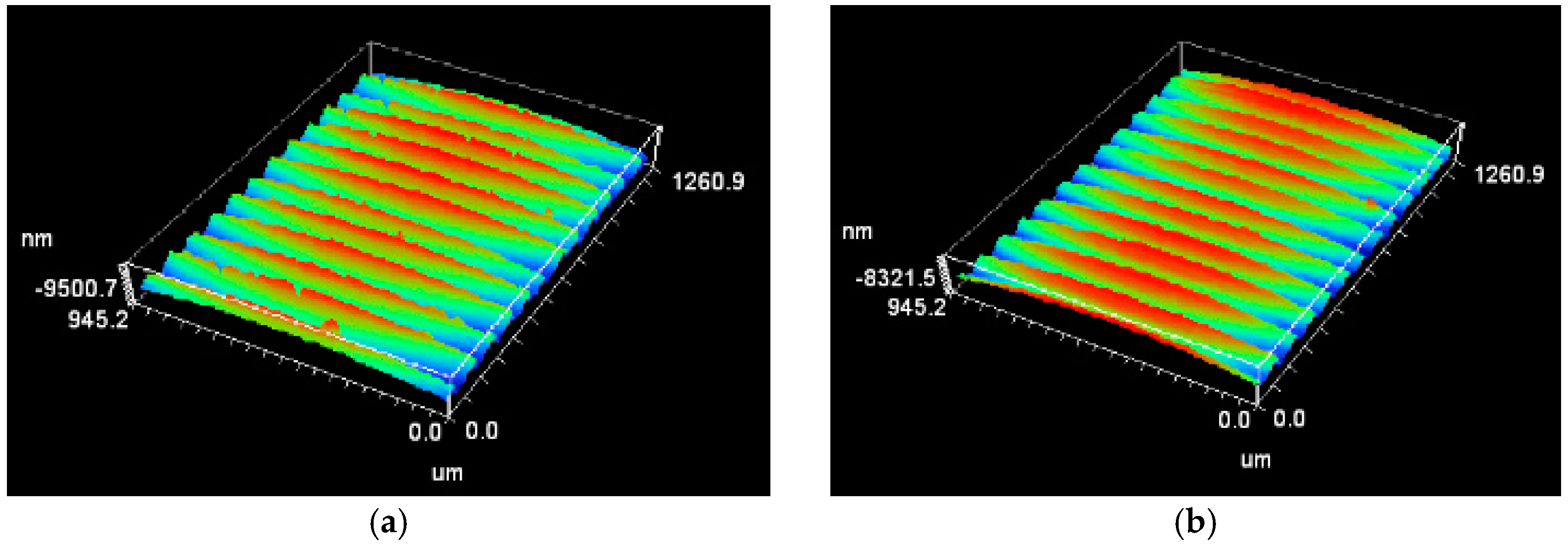
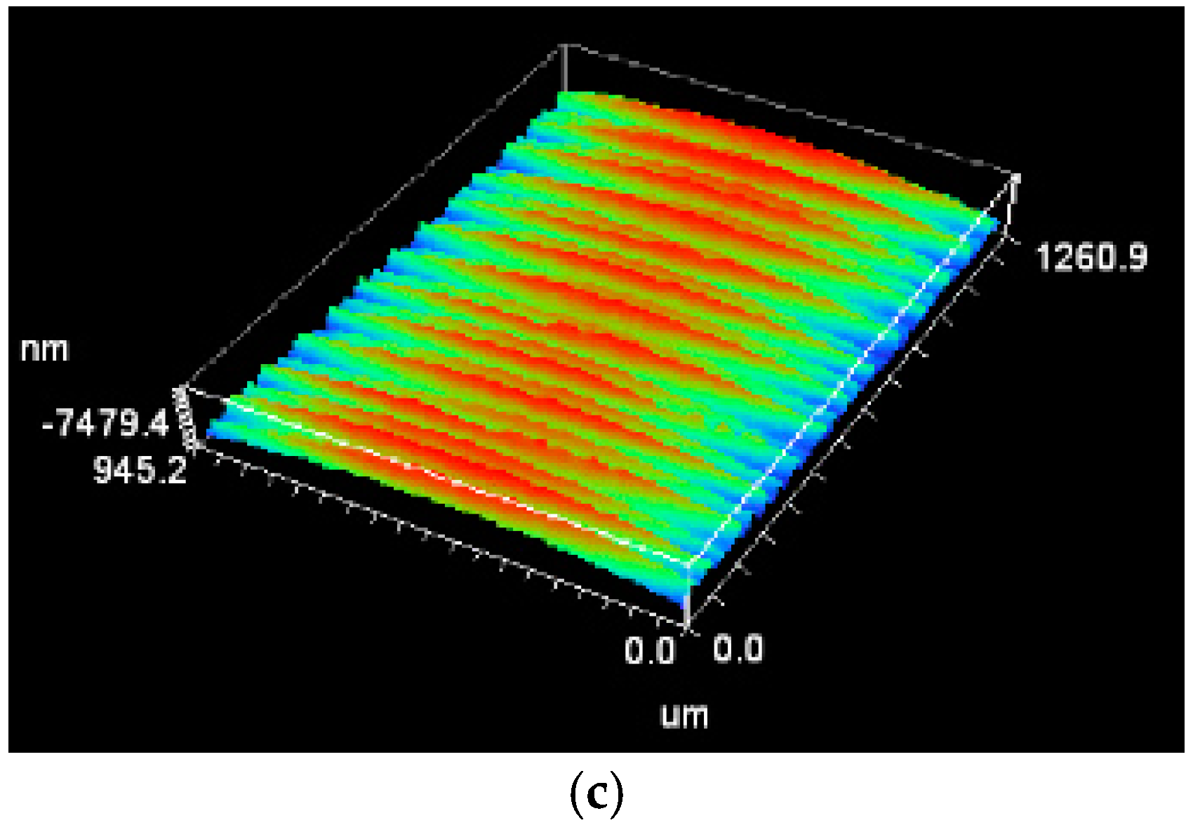
3.1. Surface Roughness of Gcr15 Cut by Normal PCBN Tools

Figure 4 is the 3D topography of GCr15 cut by normal PCBN tools at different cutting speeds. The observation shows that the surface of GCr15 was the most rough when cutting speed was v2 = 72 m/min, while the best surface morphology was obtained when v1 = 60 m/min. Randomly selecting six points was for roughness measurement, which obtained the surface roughness curves. Figure 5 is the surface roughness curve of GCr15 cut by normal PCBN tools. According to the curve trend in Figure 5, the surface quality was optimal when cutting speed was v1 = 60 m/min. However, cutting speed increased to v2 = 72 m/min, because the effect of cutting force increasing on pressure and friction on the surface of GCr15 was more serious. The heat and cutting temperature of cutting process both increased. The reason is that, at this cutting speed, the heat discharged during the cutting process is not as much as the heat generated, resulting in a higher surface temperature of the workpiece, which leads to the rough of the surface. As the cutting speed increases to v3 = 85 m/min, the heat is increasingly discharged, the hardened degree of the workpiece surface is less than the cutting speed v2 = 72 m/min, the surface stress and cutting force of the machined surface are reduced, and the pressure and friction between the tool and the workpiece can also be reduced; consequently, the surface quality is improved. In addition, the burrs on the surface of machined Gcr15 have a higher height than other cutting speeds; Zhou pointed out that the height of burrs first increased and then reduced with the increase of cutting speeds [19]. The surface burrs of the cutting workpiece were in accordance with Zhou’s theory in this test.

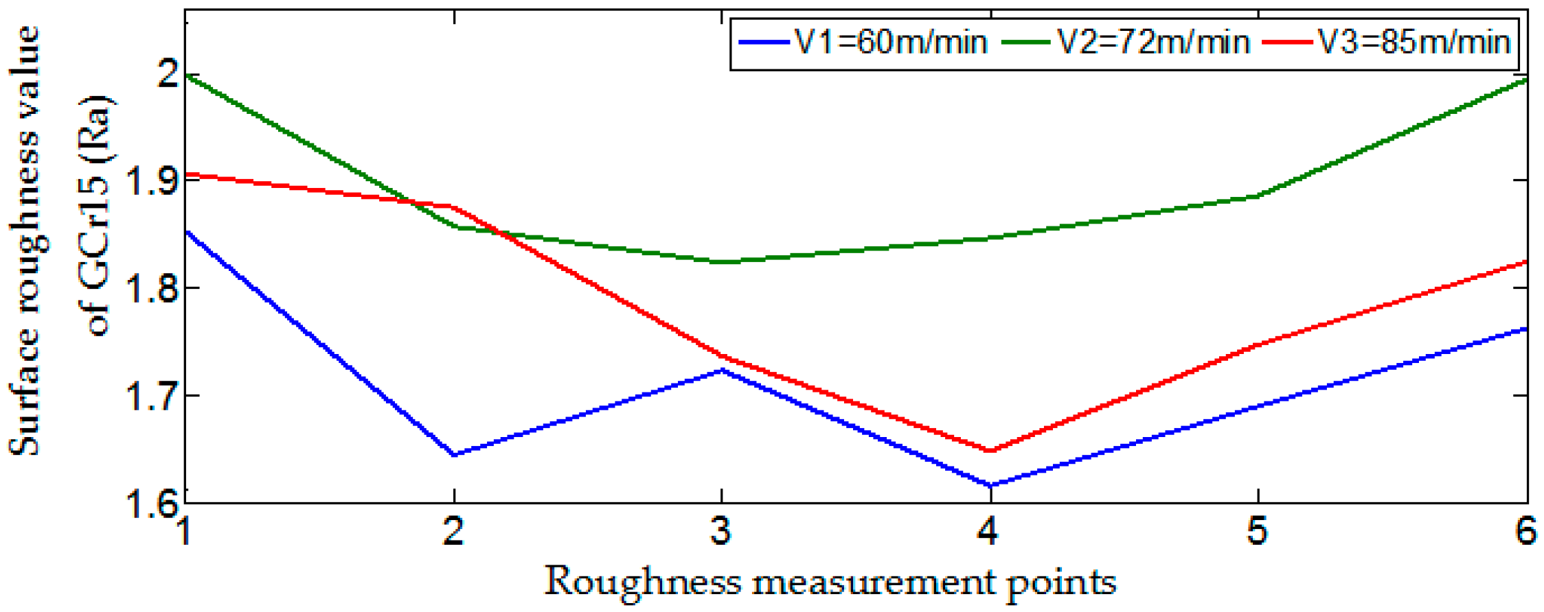
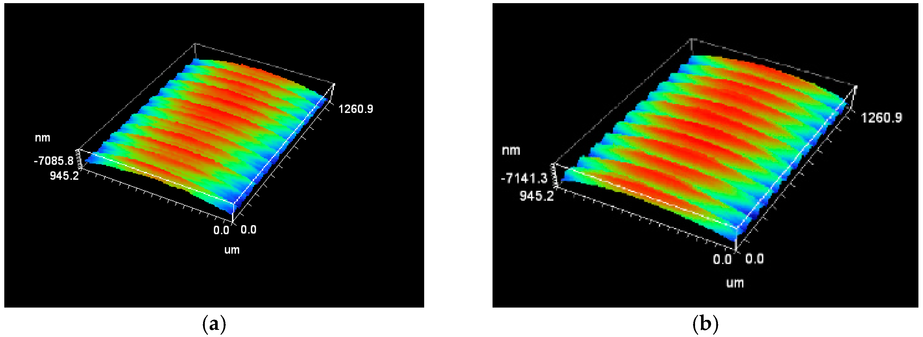
3.2. Surface Roughness of Gcr15 Cut by Vertical MicroGroove PCBN Tools

Figure 6 is the 3D topography of GCr15 cut by vertical microgroove PCBN tools at different cutting speeds, and Figure 7 is the surface roughness curve of GCr15 cut by vertical microgroove PCBN tools. The analysis of Figure 6 shows that there were different degrees of serrated burrs on machined surfaces at different cutting speeds, of which the height of the surface burrs at v2 = 72 m/min was higher and the roughness was more serious, and the serrated burrs were less at v1 = 60 m/min and v3 = 85 m/min. Observing Figure 7, we can find that the surface roughness at v1 = 60 m/min was smaller than that at v3 = 85 m/min; however, when cutting speed was v2 = 72 m/min, the surface quality was the worst and the surface roughness was highest. In the range of cutting speed set by tests, the height of serrated burrs reached a maximum at cutting speed v2 = 72 m/min, and then decreased with cutting speeds increasing. The existence of serrated burrs seriously affected surface quality, and also showed that the vertical microgrooves have no inhibition on serrated burrs of machined workpiece surface.

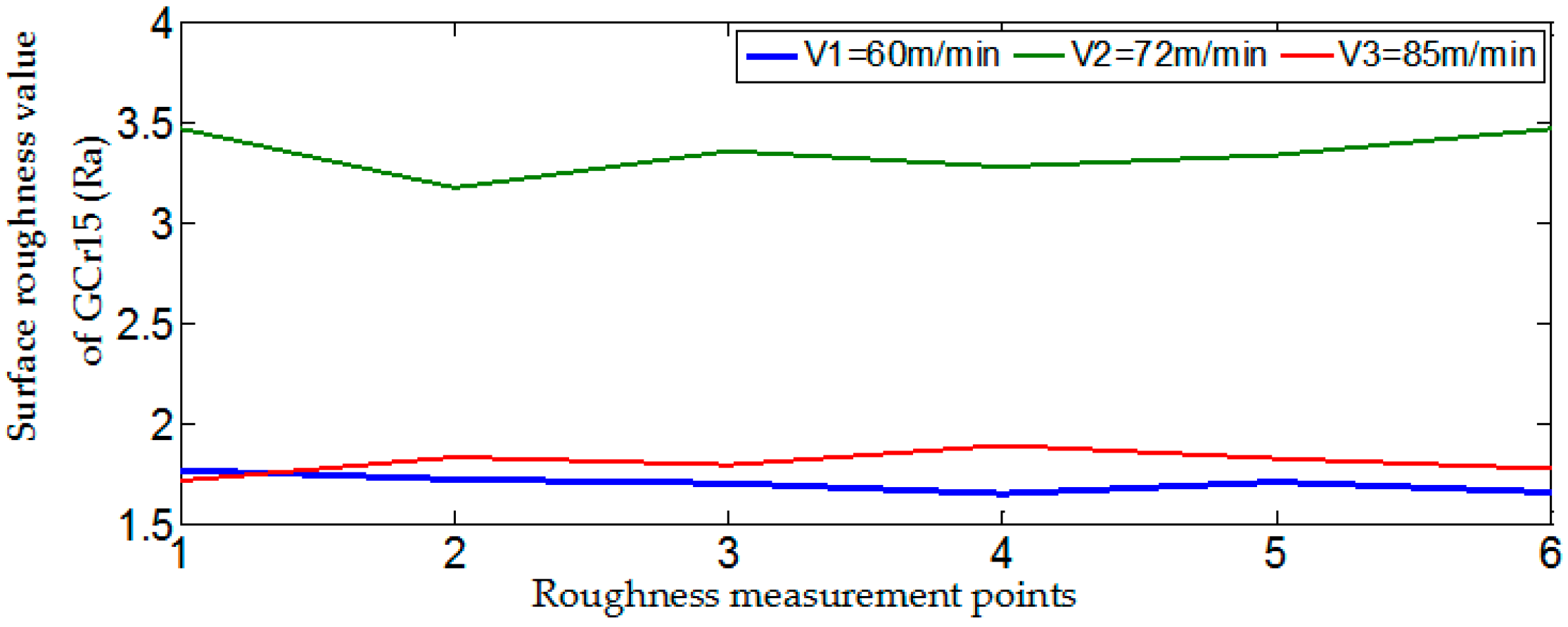
3.3. Surface Roughness of Gcr15 Cut by Parallel Microgroove PCBN Tools

Figure 8 is the 3D topography of GCr15 cut by parallel microgroove PCBN tools at different cutting speeds. Figure 8 shows that the workpiece surface was rougher at v1 = 60 m/min, and the surface quality at v3 = 85 m/min was better. Figure 9 is the surface roughness curve of GCr15 cut by parallel microgroove PCBN tools. It can be concluded that the surface roughness decreased with the increase of cutting speed, which was different from the test results of normal and vertical microgroove PCBN tools. The analysis shows that the heat dissipation of cutting heat was slower, and the heat of the workpiece surface was higher in lower speed. The surface temperature was higher and the plastic deformation of the surface metal was larger, which led to the poor surface quality. In higher speed cutting, most of the cutting heat on the surface was transmitted with the chip and the knife body, and the workpiece surface also became hardened during the process of machining, which would also affect surface quality. Compared to the three diagrams of Figure 8, it was found that the machined surface at v1 = 60 m/min had slightly serrated burrs, which showed that the lower cutting speed was not conducive to better surface quality when 40 μm parallel microgroove PCBN tools cut GCr15.

3.4. Surface Roughness of Gcr15 Cut by Microhole PCBN Tools

Figure 10 is the 3D topography of GCr15 cut by microhole PCBN tools at different cutting speeds. When cutting speed was v3 = 85 m/min, surface quality was relatively rougher, while the surface topography at v2 = 72 m/min was smoother. Figure 11 is the surface roughness curve of GCr15 cut by microhole PCBN tools. Observing the surface roughness curve of GCr15 cut by diameter 120 μm microhole tools in Figure 11, it can be concluded that the surface roughness of GCr15 was the largest at v3 = 85 m/min, and the roughness value at v1 = 60 m/min was greater than that of v2 = 72 m/min. At the same time, it can be seen from Figure 10 that there was not a large number of serrated burrs on the machined surface turned by microhole PCBN tools, which was different from normal PCBN tools, vertical microgroove PCBN tools, and parallel microgroove PCBN tools. Consequently, microhole textures had the effect of inhibiting the serrated burrs.

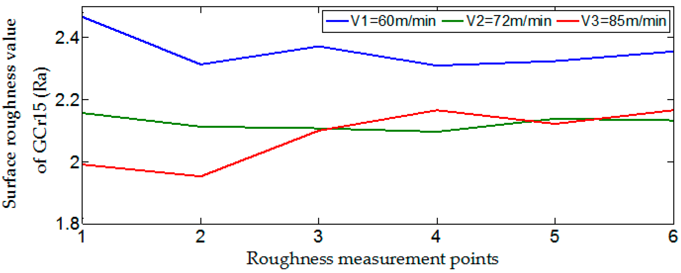
4. Analysis of Surface Roughness at Different Speeds

Figure 12 is the comparison of the surface roughness of GCr15 cut by different PCBN tools at v1 = 60 m/min. According to the curve distribution in Figure 12, the surface roughness of GCr15 cut by parallel microgroove PCBN tools was the largest, the surface roughness cut by microhole PCBN tools was minimum, and the surface roughness cut by vertical microgroove PCBN tools was lower than that of normal PCBN tools. It can be judged that parallel micro grooves were not good for good surface quality compared to normal tools at v1 = 60 m/min, while microholes and vertical microgrooves had the effect of reducing surface roughness.
Figure 13 is the comparison of the surface roughness of GCr15 cut by different PCBN tools at v2 = 72 m/min. Through the analysis of Figure 13, it was found that the surface roughness of the workpiece machined by vertical-groove tools was higher than that of other tools, and the surface quality was the worst after cutting. The surface roughness of microhole tools was still the smallest after cutting. The surface roughness of non-textured tools was also lower than that of parallel-groove tools.
Figure 14 is the comparison of the surface roughness of GCr15 cut by different PCBN tools at v3 = 85 m/min. Analyzing Figure 14, it was found that on the contrast of micro-texture tools, the maximum surface roughness of GCr15 was produced by parallel microgroove PCBN tools, followed by vertical microgroove PCBN tools, and the surface roughness was minimized by microhole PCBN tools. By calculating the average of the surface roughness, we found that the average roughness of GCr15 cut by normal PCBN tools was 1.79 μm, the average roughness of GCr15 cut by vertical microgroove PCBN tools was 1.74 μm, while the mean value of GCr15 cut by microhole tools was only 1.71 μm. It can be seen that micro holes and vertical micro grooves are favorable for reducing the surface roughness of GCr15 at v3 = 85 m/min.

5. Conclusions

Through comparison and analysis, it was found that, under experimental cutting speeds, compared to normal PCBN tools, the surface roughness of GCr15 obtained by parallel microgroove PCBN tools is larger, and parallel microgroove PCBN tools can’t machine good surface quality. In all tools, the surface roughness obtained by microhole PCBN tools was the smallest. The surface roughness obtained by vertical microgroove tools was only larger than that of normal tools at v2 = 72 m/min, but was less at other cutting speeds. From analyzing the type of micro textures, the microhole texture was more conducive to the discharge of the cutting heat, and the heat of the cutting area was not enough to make the workpiece surface seriously deformed; therefore, the surface quality of GCr15 was better. The cutting temperature of the vertical microgroove texture was lower than that of parallel microgroove texture; moreover, the vertical microgroove texture was parallel to outflow direction of chips, which can greatly reduce the friction between rake face and chip, so vertical microgroove texture is favorable for discharging cutting heat. However, a certain angle was formed between the parallel microgroove texture and the chip outflow direction, and the chip outflows will have friction with the parallel microgroove texture, which causes a relatively high cutting temperature and a relatively large deformation degree of workpiece surface; therefore, a parallel microgroove texture is not good for obtaining good surface quality. The results of this test are as follow:
(1).
Compared to normal tools, the microhole texture was the most beneficial to reducing the surface roughness of workpiece, and the vertical microgroove texture was second, while the parallel microgroove texture increased the roughness.
(2).
When 30 μm vertical microgroove tools turned GCr15 at v2 = 72 m/min, the surface quality was poor due to serrated burrs on workpiece surface, and the surface roughness of the workpiece was small at v1 = 60 m/min and v3 = 85 m/min, because lower speed and higher speed were able to inhibit the serrated burrs and to produce better surface quality.
(3).
The surface roughness obtained by 40 μm parallel microgroove tools decreased with the increase of cutting speed, but was still larger than that of normal PCBN tools.
(4).
The surface quality obtained by microhole tools was best in all cutting tests, and microhole texture had a certain inhibitory effect on serrated burrs.
In this paper, the experimental results achieved certain good results, which expands the application of micro textures, because previous research applied only more micro-texture methods in cemented carbide tools, but this method is used in PCBN tools in this paper. At the same time, this paper has played a role in promoting the application of micro-texture tools in engineering.

Author Contributions

C.P. conceived and designed the experiments, and made data curation, formal analysis, methodology, project administration, and writing-original draft; Q.L. gave the conceptualization, funding acquisition, resources, and writing-review and editing; K.H. made the project administration, software, and writing-original draft; Y.J. made the software, supervision, and data curation; Y.S. provided resources, software, and made supervision.

Funding

This research received no external funding.

Acknowledgments

Thanks Changchun University for providing test equipment and related measuring equipment. Thanks teacher for your instruction. Thanks other authors for your services.

Conflicts of Interest

There is no conflict of interests between all authors.

References

  1. Wan, Y.L.; Zhang, X.R.; Yu, H.D.; Xu, J.K.; Zhang, L.X. An Multi-index Orthogonal Test Study of Aluminum Alloy Surface Roughness Using High Speed Micro-milling Process. Chin. Mech. Eng. 2013, 24, 3278–3282. [Google Scholar]
  2. Joshua, O.S.; David, M.O.; Sikiru, I.O. Experimental Investigation of Cutting Parameters on Surface Roughness Prediction during End Milling of Aluminium 6061 under MQL (Minimum Quantity Lubrication). J. Mech. Eng. Autom. 2015, 5, 1–13. [Google Scholar]
  3. Bonţiu Pop, A.B.; Lobonţiu, M. Investigating the Effect of Cutting Speed Variation on Surface Roughness of 7136 Aluminum Alloy in End Milling. Appl. Mech. Mater. 2015, 809–810, 129–134. [Google Scholar]
  4. Luo, X.; Kou, Z.L.; Liu, T.; He, D.W.; Peng, F.; Lei, L. Edge Preparation of PCD Cutting Tools and Influence on Surface roughness while Turning Aluminum. Tool Eng. 2016, 50, 17–20. [Google Scholar]
  5. Wang, M.H.; Li, S.Y.; Zheng, Y.H. Surface roughness of Titanium Alloy under Ultrasonic Vibration Milling. Trans. Soc. Agric. Mach. 2014, 45, 341–346. [Google Scholar]
  6. Li, J.; Ren, C.Z.; Yang, X.Y.; Chen, G.; He, Y.L. Effects of milling parameters on surface integrity of titanium alloy (Ti-6Al-4V). J. Mach. Des. 2016, 33, 1–6. [Google Scholar]
  7. Oliaei, S.N.B.; Karpat, Y. Investigating the influence of built-up edge on forces and surface roughness in micro scale orthogonal machining of titanium alloy Ti6Al4V. J. Mater. Process. Technol. 2016, 235, 28–40. [Google Scholar] [CrossRef] [Green Version]
  8. Du, S.Y.; Chen, M.H.; Zhu, Z.S.; Wang, X.N. Experimental research on Surface Integrity of Milling New Ultra-High Strength Titanium Alloy TB17. Modul. Mach. Tool Autom. Manuf. Tech. 2017, 4, 125–129. [Google Scholar]
  9. Wang, X.S.; Kang, M.; FU, X.Q.; Li, C.L. Prediction Model of Surface Roughness in Lenses Precision Turning. J. Mech. Eng. 2013, 49, 192–198. [Google Scholar] [CrossRef]
  10. Li, C.L.; Kang, M.; Wang, X.S.; Chen, X. Roughness Prediction and Process Parameter Optimization of Lens Turning. Piezoelectr. Acoustoop. 2015, 37, 796–801. [Google Scholar]
  11. Luo, Z.W.; Jiao, L.; Zhao, W.X.; Yuan, M.X.; Wang, L.L. Experimental Investigation of Surface Integrity in Turning of High Strength Steel 58SiMn. Surf. Technol. 2017, 46, 234–240. [Google Scholar]
  12. Khatri, N.; Mishra, V.; Sharma, R.; Garg, H.; Kara, V. Improving the Surface Finish of Diamond Turned Silicon with Magneto-Rheological Finishing. Mater. Today Proc. 2017, 4, 10158–10162. [Google Scholar] [CrossRef]
  13. Suresh, R.; Basavarajappa, S. Effect of Process Parameters on Tool Wear and Surface Roughness during Turning of Hardened Steel with Coated Ceramic Tool. Procedia Mater. Sci. 2014, 5, 1450–1459. [Google Scholar] [CrossRef]
  14. Liu, X.C.; Chen, F.; He, Q.P.; Feng, M.S.; Ji, W.X. Research of GCr15 Bearing Steel’s Surface Roughness and Grinding Burn in Ultra-high Speed Grinding. Modul. Mach. Tool Autom. Manuf. Tech. 2016, 9, 32–34. [Google Scholar]
  15. Krolczyk, G.M.; Maruda, R.W.; Nieslony, P.; Wieczorowski, M. Surface morphology analysis of Duplex Stainless Steel (DSS) in Clean Production using the Power Spectral Density. Measurement 2016, 94, 464–470. [Google Scholar] [CrossRef]
  16. Krolczyk, G.M.; Maruda, R.W.; Krolczyk, J.B.; Nieslony, P.; Wojciechowski, S.; Legutko, S. Parametric and nonparametric description of the surface topography in the dry and MQCL cutting conditions. Measurement 2018, 121, 225–239. [Google Scholar] [CrossRef]
  17. Liu, J.; Lu, E.; Yi, H.; Wang, M.H.; Ao, P. A new surface roughness measurement method based on a color distribution statistical matrix. Measurement 2017, 103, 165–178. [Google Scholar] [CrossRef]
  18. Chen, Y.; Sun, R.; Gao, Y.; Leopold, J. A nested-ANN prediction model for surface roughness considering the effects of cutting forces and tool vibrations. Measurement 2017, 98, 25–34. [Google Scholar] [CrossRef]
  19. Zhou, Z.H. Metallurgica Cutting Theory, 2nd ed.; China Machine Press: Beijing, China, 1992; pp. 154–164. [Google Scholar]
Figure 1. The CNGA120408 PCBN tool.
Machines 06 00042 g001
Figure 2. Surface morphology of micro-texture tools: (a) 30 μm vertical microgrooves; (b) 40 μm parallel microgrooves; (c) microholes of 120 μm in diameter.
Machines 06 00042 g002
Figure 3. The GCr15 workpiece.
Machines 06 00042 g003
Figure 4. The 3D topography of GCr15 cut by normal PCBN tools at different cutting speeds: (a) v1 = 60 m/min; (b) v2 = 72 m/min; (c) v3 = 85 m/min.
Machines 06 00042 g004aMachines 06 00042 g004b
Figure 5. Surface roughness curve of GCr15 cut by normal PCBN tools.
Machines 06 00042 g005
Figure 6. The 3D topography of GCr15 cut by vertical microgroove PCBN tools at different cutting speeds: (a) v1 = 60 m/min; (b) v2 = 72 m/min; (c) v3 = 85 m/min.
Machines 06 00042 g006aMachines 06 00042 g006b
Figure 7. Surface roughness curve of GCr15 cut by vertical microgroove PCBN tools.
Machines 06 00042 g007
Figure 8. The 3D topography of GCr15 cut by parallel microgroove PCBN tools at different cutting speeds: (a) v1 = 60 m/min; (b) v2 = 72 m/min; (c) v3 = 85 m/min.
Machines 06 00042 g008aMachines 06 00042 g008b
Figure 9. Surface roughness curve of GCr15 cut by parallel microgroove PCBN tools.
Machines 06 00042 g009
Figure 10. The 3D topography of GCr15 cut by microhole PCBN tools at different cutting speeds: (a) v1 = 60 m/min; (b) v2 = 72 m/min; (c) v3 = 85 m/min.
Machines 06 00042 g010aMachines 06 00042 g010b
Figure 11. Surface roughness curve of GCr15 cut by microhole PCBN tools.
Machines 06 00042 g011
Figure 12. The comparison of the surface roughness of GCr15 cut by different PCBN tools at v1 = 60 m/min.
Machines 06 00042 g012
Figure 13. The comparison of the surface roughness of GCr15 cut by different PCBN tools at v2 = 72 m/min.
Machines 06 00042 g013
Figure 14. The comparison of the surface roughness of GCr15 cut by different PCBN tools at v3 = 85 m/min.
Machines 06 00042 g014
Table 1. The micro textures’ size.
Type of MicrotextureWidth/Diameter (μm)Depth (μm)Distance from the Cutting Edge (μm)Number
Vertical microgrooves30520010
Parallel microgrooves4052008
Microholes12053509

