Article

Joint Mechanism That Mimics Elastic Characteristics in Human Running

1
Graduate School of Science and Engineering, Waseda University, No. 41-304, 17 Kikui-cho, Shinjuku-ku, Tokyo 162-0044, Japan
2
Waseda Institute for Advanced Study, Waseda University, No. 41-304, 17 Kikui-cho, Shinjuku-ku, Tokyo 162-0044, Japan
3
Humanoid Robotics Institute (HRI), Waseda University, 2-2 Wakamatsu-cho, Shinjuku-ku, Tokyo 162-8480, Japan
4
Faculty of Kinesiology, University of Calgary, 2500 University Drive NW, Calgary, AB T2N 1N4, Canada
5
Faculty of Sport Sciences, Waseda University, 2-579-15 Mikajima, Tokorozawa-shi, Tokyo 359-1192, Japan
6
Faculty of Engineering, Kanagawa University, 3-27-1 Rokkakubashi, Kanagawa-ku, Yokohama 221-8686, Japan
7
Department of Modern Mechanical Engineering, Waseda University, 2-2 Wakamatsu-cho, Shinjuku-ku, Tokyo 162-8480, Japan
*
Author to whom correspondence should be addressed.
These authors contributed equally to this work.
Machines 2016, 4(1), 5; https://doi.org/10.3390/machines4010005
Submission received: 31 July 2015 / Revised: 11 January 2016 / Accepted: 19 January 2016 / Published: 25 January 2016
(This article belongs to the Special Issue Mechanical Designs for Humanoids Robots: Problems and Solutions)

Abstract

:
Analysis of human running has revealed that the motion of the human leg can be modeled by a compression spring because the joints of the leg behave like a torsion spring in the stance phase. In this paper, we describe the development of a joint mechanism that mimics the elastic characteristics of the joints of the stance leg. The knee was equipped with a mechanism comprising two laminated leaf springs made of carbon fiber-reinforced plastic for adjusting the joint stiffness and a worm gear in order to achieve active movement. Using this mechanism, we were able to achieve joint stiffness mimicking that of a human knee joint that can be adjusted by varying the effective length of one of the laminated leaf springs. The equation proposed for calculating the joint stiffness considers the difference between the position of the fixed point of the leaf spring and the position of the rotational center of the joint. We evaluated the performance of the laminated leaf spring and the effectiveness of the proposed equation for joint stiffness. We were able to make a bipedal robot run with one leg using pelvic oscillation for storing energy produced by the resonance related to leg elasticity.

1. Introduction

We previously researched the development of a bipedal humanoid robot that can mimic various characteristics of human walking; this robot was used for investigating human mechanisms and human motion control [1,2,3]. For improving the performance of this robot and using this robot for not only walking, but also hopping and running, we have initiated the development of a new bipedal humanoid robot that can run like a human. In human sciences and sports sciences, researchers usually perform motion capture experiments to realize human motions. In motion capture experiments, however, motions that pose a risk of injury to human subjects cannot be studied owing to ethical concerns [4], despite the possibility of improving those motions through coordinated training. If a robot that can mimic human hopping and running were developed, it would become possible to mimic other human motions, as well. Furthermore, if a robot could perform motions that would improve sports performance, but would be dangerous if a human being were to perform them, it would be possible to identify more effective human motions.
Relevant studies in human sciences have identified some characteristics of human running, such as the following:
  • A stance leg acts like a linear spring, and a human leg can be modeled as a spring-loaded inverted pendulum (SLIP) [5,6,7].
  • The knee and ankle joints of a stance leg act like torsion springs [8,9].
  • The knee joint stiffness of the stance leg changes with running speed [8,10].
  • Rapid knee bending occurs in the swing phase to avoid contact of the foot with the ground [11].
  • Pelvis rotation in the frontal plane increases jumping force [12].
  • Moment compensation is accomplished using the upper body and arms [13].
In human running, the joints of the leg require more than 1000 W of power [11,14,15,16], which is greater than the power of the actuator found in an ordinary life-sized humanoid robot [1,17,18,19,20]. To exert a high output during the stance phase, humans utilize joint stiffness for storing the kinetic energy that the robot has during the flight phase. Therefore, we focused on the leg stiffness and joint stiffness of the stance leg as the characteristics that are absolutely necessary for attaining jumping power. There are some studies on running using humanoid robots, but few robots can mimic this characteristic. Some small humanoids can run, but the dynamics of these robots are different from those of humans [21]. Life-sized humanoid robots [17,18], such as ASIMO [19] and Toyota’s humanoid robot [20], do not have human-like leg elasticity. One athletic robot has a human-like musculoskeletal system in the leg and elastic parts in the foot, as with an artificial leg, but this robot’s ankle joint does not mimic human ankle joint stiffness [22]. MABEL [23] also has variable-stiffness joints for running and succeeded in running with axial constraints on the Y-axis, but it cannot vary its joint stiffness within a range equivalent to that of human joint stiffness. Elastic joint mechanisms were developed for walking humanoids, such as COMAN [24,25,26], so that they can interact with the environment safely or mimic human mechanisms [27,28]. However, the joint mechanisms cannot output enough torque for a running life-sized humanoid robot. Some artificial legs have been developed for achieving natural locomotion; however, they mimic only ankle stiffness, not knee joint stiffness, and the amount of joint stiffness is not equal to that of a human [29,30,31,32].
Our intention in this study was to develop a joint mechanism with variable joint stiffness that mimics human joint stiffness and that can be utilized for running. In addition, the knee joint should bend in the swing phase to avoid contact between the foot and the ground. The ankle joint should produce a torque that is the same as that of the knee; however, the joint stiffness of the ankle does not change according to the running speed, and the ankle joint does not bend like a knee joint during the flight phase. Thus, the knee joint mechanism should incorporate joint stiffness and should move actively during the flight phase. We developed a mechanism comprising two laminated leaf springs made of carbon fiber-reinforced plastic (CFRP) for adjusting joint stiffness and a worm gear that can change the angle between two laminated leaf springs with an actuator for achieving active movement. We evaluated the laminated leaf spring and then performed a hopping experiment to evaluate the effectiveness of the proposed joint mechanism.
This paper is organized as follows. In Section 2, we describe the design of the joint mechanism that mimics human joint stiffness. In Section 3, we present and discuss experimental results. Finally, in Section 4, we present conclusions and propose future work.

2. Joint Mechanism Mimicking the Joint Stiffness of a Human Leg

2.1. Requirements for a Joint Mechanism Based on Human Running

During the stance phase of human running, the knee and ankle joints alternately lengthen and shrink like a spring, whereas the hip joint, unlike a spring, only lengthens [7,8,14,15]. The leg stiffness is a result of knee and ankle joint stiffness, and joint stiffness is important for attaining jumping force. As mentioned above, leg stiffness and joint stiffness vary during the flight phase according to running speed [8,10]. We began by determining the requirements for the robotic joint based on human running data; we considered running speeds between 4 m/s and 10 m/s. The requirements for achieving the joint stiffness of a running human leg were obtained from the results of our preliminary analysis and published running data (see Table 1) [12,14,16]. From these data, we conclude that the knee joint should produce a torque of 177 Nm in the stance phase, bend 2.7 rad in the swing phase and be able to vary its stiffness as needed within the range of human knee joint stiffness, from 300 Nm/rad at a running speed of 4 m/s to 600 Nm/rad at a running speed of 10 m/s, during the swing phase, which has a duration of 0.4 s. Based on knee bending, we calculated a required angular velocity of 6.7 rad/s.
Table 1. Joint stiffness for human running.
Min. (Nm/rad)Max. (Nm/rad)
Knee300600
Ankle520570

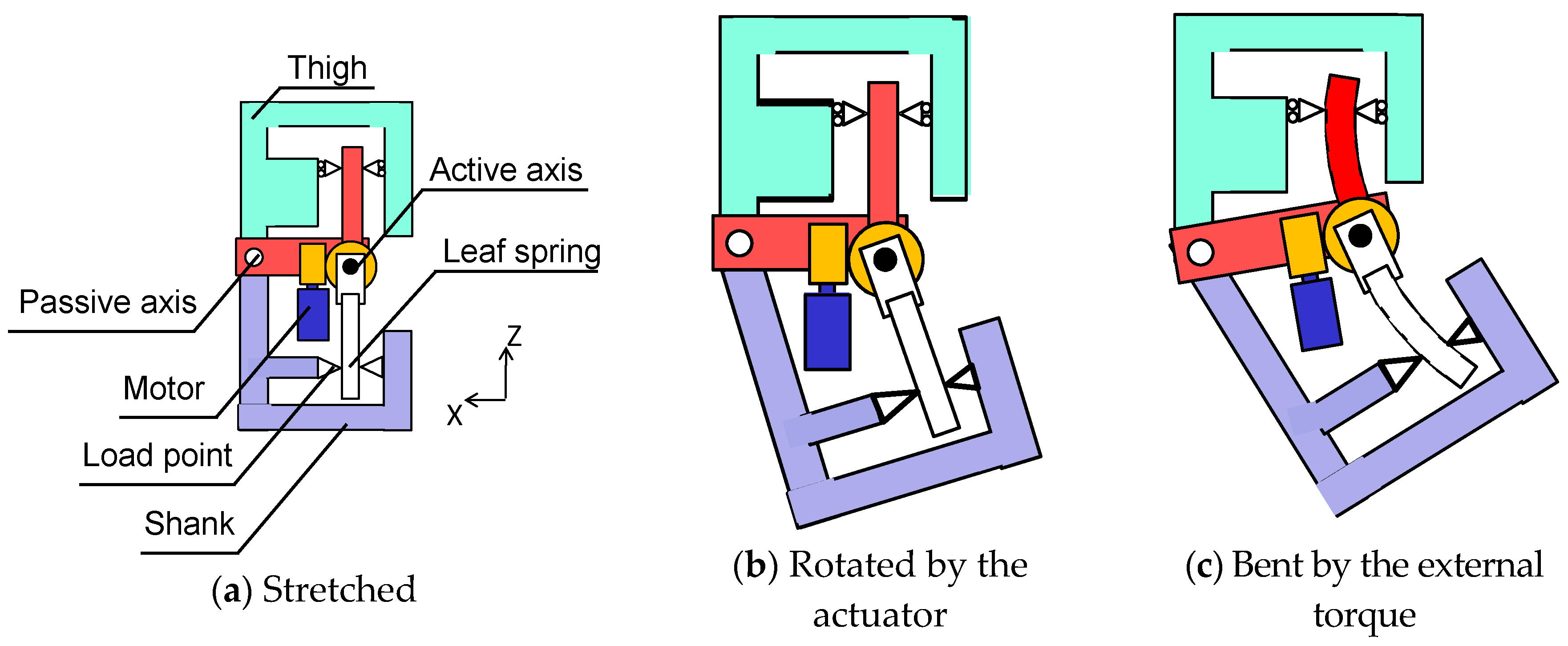
2.2. Design of a Joint Mechanism Mimicking the Joint Stiffness of a Human Leg

There are several methods of mimicking joint stiffness, including using an actuator to control the joint like a spring, implementing a spring and using a combination of these methods. In human running, each joint of the leg requires more than 1000 W [11,14,15,16], whereas the output of the DC motors used in the legs of some humanoid robots is much lower: approximately 150 W [1,17,18,19,20]. If motors with higher power were used, their size and weight would make it difficult to mimic a human leg. Although hydraulic actuators can be used to produce the required high output, they require large, heavy pumps. It is therefore very difficult to realize human running using existing actuators. Consequently, we considered the possibility of mimicking this characteristic by using elastic bodies, such as a compression coil spring, a torsion spring or a leaf spring. To mimic the variation of joint stiffness with running speed, we used a leaf spring, with which we can easily adjust the stiffness by varying the distance between a supporting point and a load point [33]. Figure 1 is a schematic of the joint stiffness adjustment mechanism. The load point is fixed on Link A, and the leaf spring is fixed on Link B via the joint axis. When a force is applied to Link A, the force is transmitted to the leaf spring through the load point. Link A then rotates in accordance with the deformation of the leaf spring. In this way, we can adjust the joint stiffness by changing the position of the load point. This stiffness can be calculated as:
K j = M Δ θ
where K j is the joint stiffness, M is the joint torque and Δ θ is the joint displacement. The formula for the joint displacement is the following:
Δ θ = tan 1 ( δ / L )
where δ is the deflection of the leaf spring and L is the effective length of the leaf spring. When the displacement is small, it can be approximated as follows:
Δ θ δ / L
Figure 1. Schematic of the joint stiffness adjustment mechanism.
Machines 04 00005 g001
The deflection is expressed as follows:
δ = M L 2 3 E I = 4 M L 2 b t 3 E
where E is the Young’s modulus of the leaf spring, I is the area moment of inertia of the leaf spring, b is the width of the leaf spring and t is the thickness of the leaf spring. According to these equations, the joint stiffness can be approximated as follows:
K j = 3 E I L = b t 3 E 4 L
The joint stiffness adjustment mechanism allows for changing the stiffness of the joint. However, when we attempted to mimic low joint stiffness, it was difficult to install the leaf spring in a manner that is consistent with human physical structure. We need to position the load point far from the supporting point to mimic low joint stiffness, and furthermore, the leaf spring cannot withstand the force while in the stance phase if its thickness is reduced to decrease the stiffness. Thus, this leaf spring joint stiffness adjustment mechanism cannot achieve the required joint stiffness. To resolve this problem, we incorporated an additional leaf spring into the mechanism. The two leaf springs were implemented in series through the active actuator in the joint to realize low joint stiffness. This arrangement makes it possible to adjust the stiffness of the joint over a wide range. Moreover, the approximation of the displacement becomes more accurate because the deflection of a leaf spring becomes half of the displacement of the joint mechanism. Therefore, we used the above simplification (Equation (3)) for calculating joint stiffness. The theoretical formula for joint stiffness using two leaf springs is the following:
K j = K a d j u s t a b l e K f i x e d K a d j u s t a b l e + K f i x e d
where K j is the joint stiffness, K a d j u s t a b l e is the stiffness of the leaf spring whose effective length we can change and K f i x e d is the stiffness of the leaf spring whose effective length is fixed. Furthermore, we devised a new joint mechanism in which the angle between two leaf springs can be changed by an actuator in order to achieve active movement. The two leaf springs transmit the joint torque to an upper link and a lower link through the load point, which can be moved to change the effective length (see Figure 2a). When the active joint moves, the joint rotates (see Figure 2b). When the external torque is applied, the leaf springs bend, and the joint angle also changes (see Figure 2c). If this mechanism is to act like a torsion spring, the angle between the two leaf springs should be fixed, and only the leaf springs should bend to produce the joint torque while the robot is standing. To accomplish this, we used a worm gear to which the torque from an input shaft to an output shaft is transmitted; not all of the torque from the output shaft to the input shaft is transmitted to the worm gear. The transmission efficiency was changed according to the lead angle γ of the worm gear. The theoretical formulas for transmission efficiency from the input shaft to the output shaft ( η 1 ) and from the output shaft to the input shaft ( η 2 ) are as follows [34]:
η 1 = tan γ tan ( γ + ρ )
η 2 = tan ( γ - ρ ) tan γ
where ρ is a parameter with a value of 0.14, determined by the material of which the worm gear is made and the angular velocity during running. These formulas are plotted in Figure 3. The lead angle was determined to be 8.73° considering the feasibility of manufacturing and the back-drivability. Using these formulas, we designed the worm gear so that it would be possible to fix the angle between the leaf springs and move actively by using the motor, which can output 150 W and is small and light enough to be implemented in the leg. The torque transmission efficiency from the input shaft to the output shaft of the developed mechanism is 50%, and that from the output shaft to the input shaft is 2.6%. This knee mechanism (see Figure 4) can fix the angle between the two leaf springs in the stance phase and actively control the joint angle.
Figure 2. Schematic of the knee mechanism comprising two leaf springs.
Machines 04 00005 g002
Figure 3. Influence of lead angle on torque transmission efficiency.
Machines 04 00005 g003
To vary the joint stiffness within the range of a human leg joint, the load point must move 130 mm in 0.4 s. In addition, the mechanism should withstand a load of 10,000 N in the direction perpendicular to the leaf spring and a load of 750 N in the direction parallel to the leaf spring. There are several ways of moving the load point, such as using a ball screw or a rack-and-pinion system. When a rack-and-pinion system is used, the actuator needs more power to move itself because it moves with the load point. Therefore, we decided to use a ball screw. When a ball screw is used, the large load in the direction parallel to the leaf spring produces a large moment that acts on the actuator. To make it possible for the actuator to withstand this large load and moment, we implemented an electrical break to control the moment and a linear guide for the load in the direction perpendicular to the leaf spring (see Figure 5). Thanks to this mechanism, the load point can be adjusted during the flight phase like a human.
Figure 4. CAD model for the knee mechanism comprising two leaf springs and a worm gear.
Machines 04 00005 g004
Figure 5. CAD model for the joint stiffness adjustment mechanism.
Machines 04 00005 g005

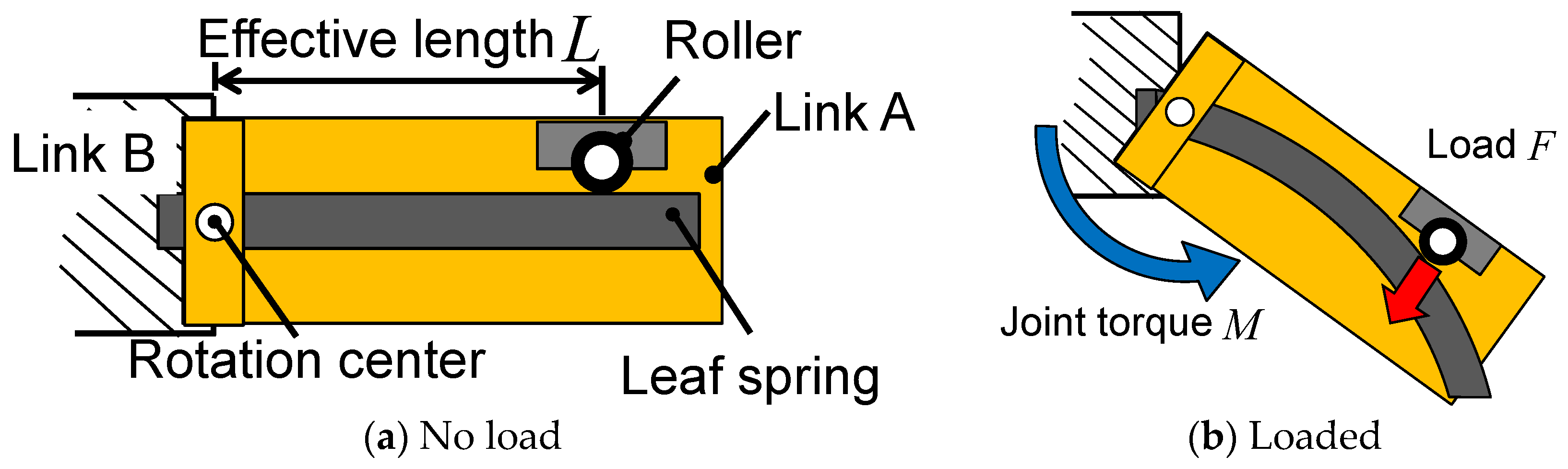
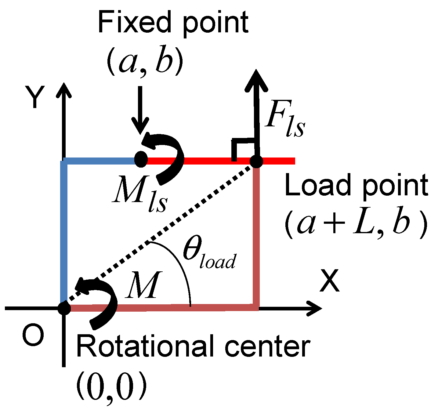
2.3. Joint Stiffness Equation Considering the Fixed Point

The position of the fixed point of the leaf spring is different from the rotational center of the joint in the developed joint mechanism (see Figure 6). Because the difference between the rotational center and the fixed point of the leaf spring influences the moment of the leaf spring, we modified the equation for the stiffness of the mechanism.
When the position of the fixed point and that of the rotational center are different, the positions can be expressed in terms of their two-dimensional coordinates. The coordinates of the rotational center are set as the origin of the coordinate system. The coordinates of the fixed point are ( a , h ), and those of the load point are ( a + l , h ). When moment M is applied to the rotational center, force F l s is applied to the load point of the leaf spring. This force is expressed as follows:
F l s = M a + L
Moment M l s applied to the load spring is expressed as follows:
M l s = L F l s
Based on these equations, this moment bending the leaf spring is calculated as follows:
M l s = L a + L M
According to Equation (11), when the positions of the rotational center and the fixed point of the leaf spring are the same, i.e., a equals zero, the moment acting on the leaf spring is the same as that acting on the joint. However, when a > 0, the moment acting on the leaf spring is smaller than that acting on the joint. This means that the deflection of the leaf spring δ l s also becomes smaller:
δ l s = 4 M l s L 2 b t 3 E = 4 M L 3 ( a + L ) b t 3 E
For calculating the joint stiffness with Equations (1) and (3), the deflection δ perpendicular to the line that passes through the rotational center and the load point is expressed as follows:
δ = δ l s cos θ l o a d = a + L ( a + L ) 2 + b 2 δ l s
where θ l o a d is the angle between the X direction and the line that passes through the rotational center and the load point. According to the modified deflection given in Equation (13), the modified theoretical formula for the joint stiffness is the following:
K j = b t 3 E 4 L 2 ( a + L ) 2 + b 2
where K j is the modified joint stiffness. This indicates that a greater difference between the rotational center and the fixed point of the leaf spring leads to increased joint stiffness. We took this into consideration in the design of the leaf spring.
Figure 6. Influence of the difference between the rotational center and the fixed point of the leaf spring.
Machines 04 00005 g006

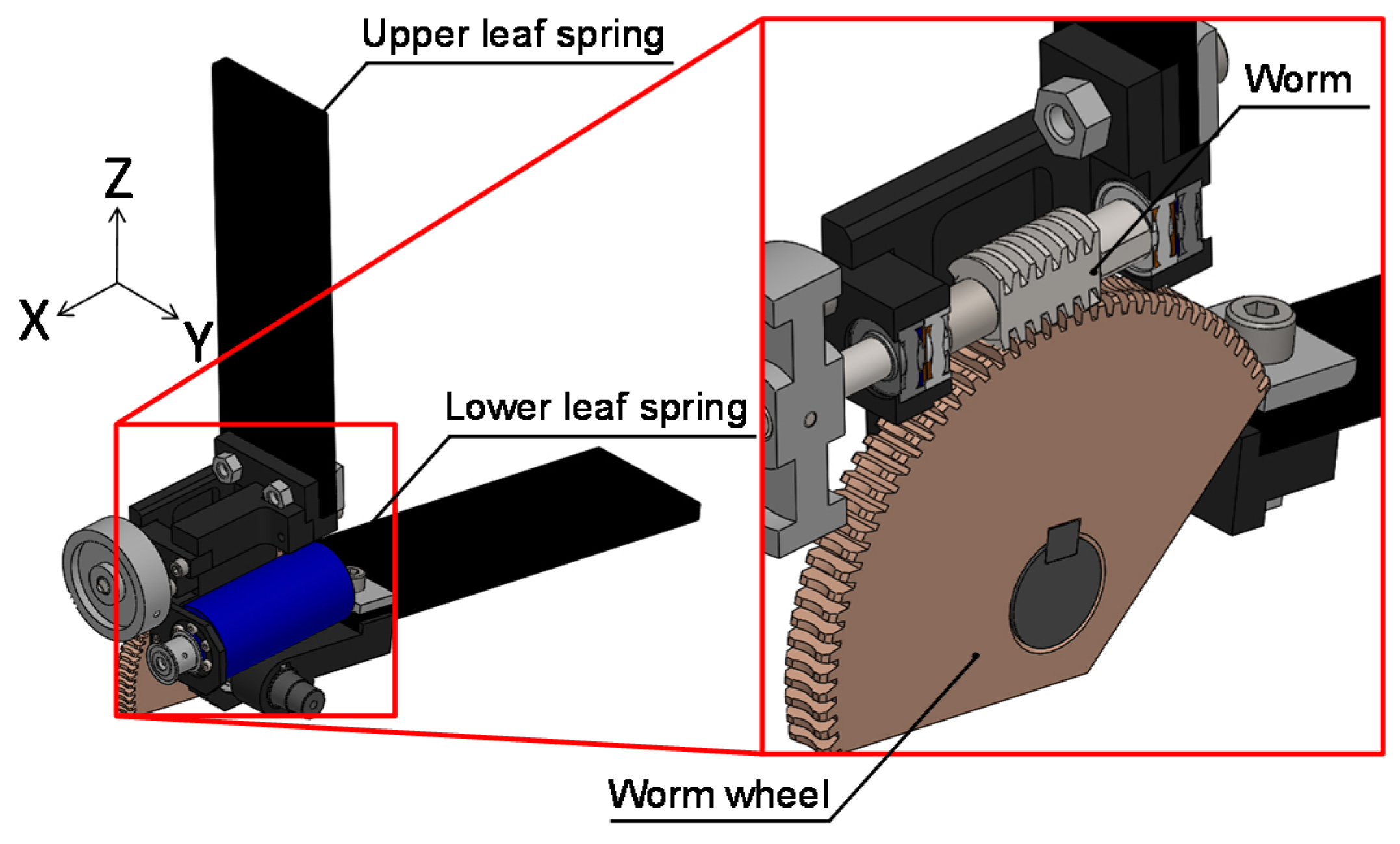
2.4. Laminated Leaf Spring Made of Carbon Fiber-Reinforced Plastic

In order to incorporate the leaf springs into the developed joint mechanism, the leaf springs must be able to withstand a large load while the robot is running. One option is to make the leaf spring out of iron. Such a leaf spring could withstand a large load, but it would be very heavy. If an iron leaf spring were implemented, the joint mechanism would not be able to mimic the mass of a human leg.
To resolve this problem, we used a leaf spring made of CFRP, which is extremely strong, yet also light. The specific strength of CFRP (2457 kNm/kg) is much higher than that of iron (254 kNm/kg), and the density of CFRP (1.5 g/cm3) is much lower than that of iron (7.8 g/cm3). On account of these characteristics, CFRP is used in some prosthetic legs [29]. However, when the CFRP leaf spring was made small enough to be installed into a robotic leg equivalent in size to a human leg, the stress on the leaf spring exceeded its strength. To improve the strength, the thickness or width of the leaf spring should be increased. However, when the width is increased, it becomes difficult to incorporate the leaf spring into the leg. On the other hand, when the thickness is increased, the deflection of the leaf spring becomes smaller and the joint stiffness higher than that of a human leg. To resolve this problem, we stacked two leaf springs, one upon another. The maximum stress σ is expressed as follows:
σ = 6 M b t 2
In contrast, the deflection of the laminated leaf spring and the maximum stress on one leaf spring in the laminated leaf spring are expressed as follows:
δ laminated = 6 M L 2 n b t 3 E
σ laminated = 6 M n b t 2
where t is the thickness of each leaf spring and n is the number of leaf springs. Thus, t is expressed as follows:
t = t n
Considering Equation (18), Equations (16) and (17) can be expressed as follows:
δ laminated = 6 n 2 M L 2 b t 3 E
σ laminated = 6 n M b t 2
Based on Equations (19) and (20), when the number of leaf springs increases, the deflection and the stress also increase. However, the number of leaf springs influences the deflection more than the stress. Thus, we can adjust the total thickness to modify the strength and the number of leaf springs to modify the joint stiffness. To increase the strength of the leaf spring and decrease the joint stiffness, we used these formulas to design a laminated leaf spring made of two CFRP leaf springs. Compared to an iron leaf spring whose joint stiffness is the same as that of the laminated CFRP leaf spring, the laminated leaf spring is thicker and almost the same in length and width, and the mass of the laminated leaf spring (200 g) is much lower than that of the iron leaf spring (600 g) (see Table 2). Furthermore, the mass of the joint mechanism using the CFRP laminated leaf springs is 3000 g, compared to 3800 g for the joint with iron leaf springs. Thus, the use of CFRP laminated leaf springs reduces the mass of the joint by approximately 21%.
Table 2. Leaf spring characteristics.
MaterialIronCFRP
Size mm250 × 90 × 3.4220 × 70 × 8.8
Mass g600200

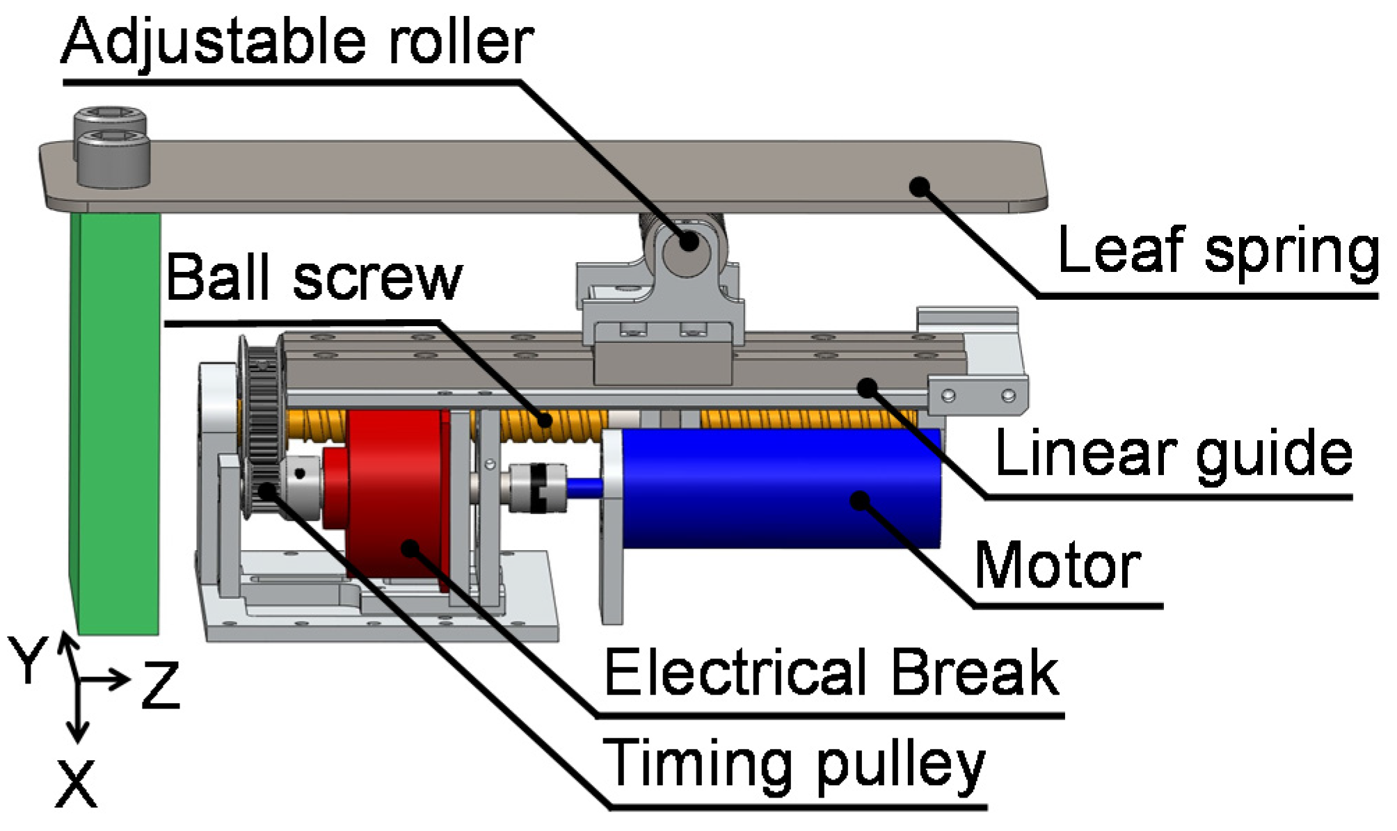
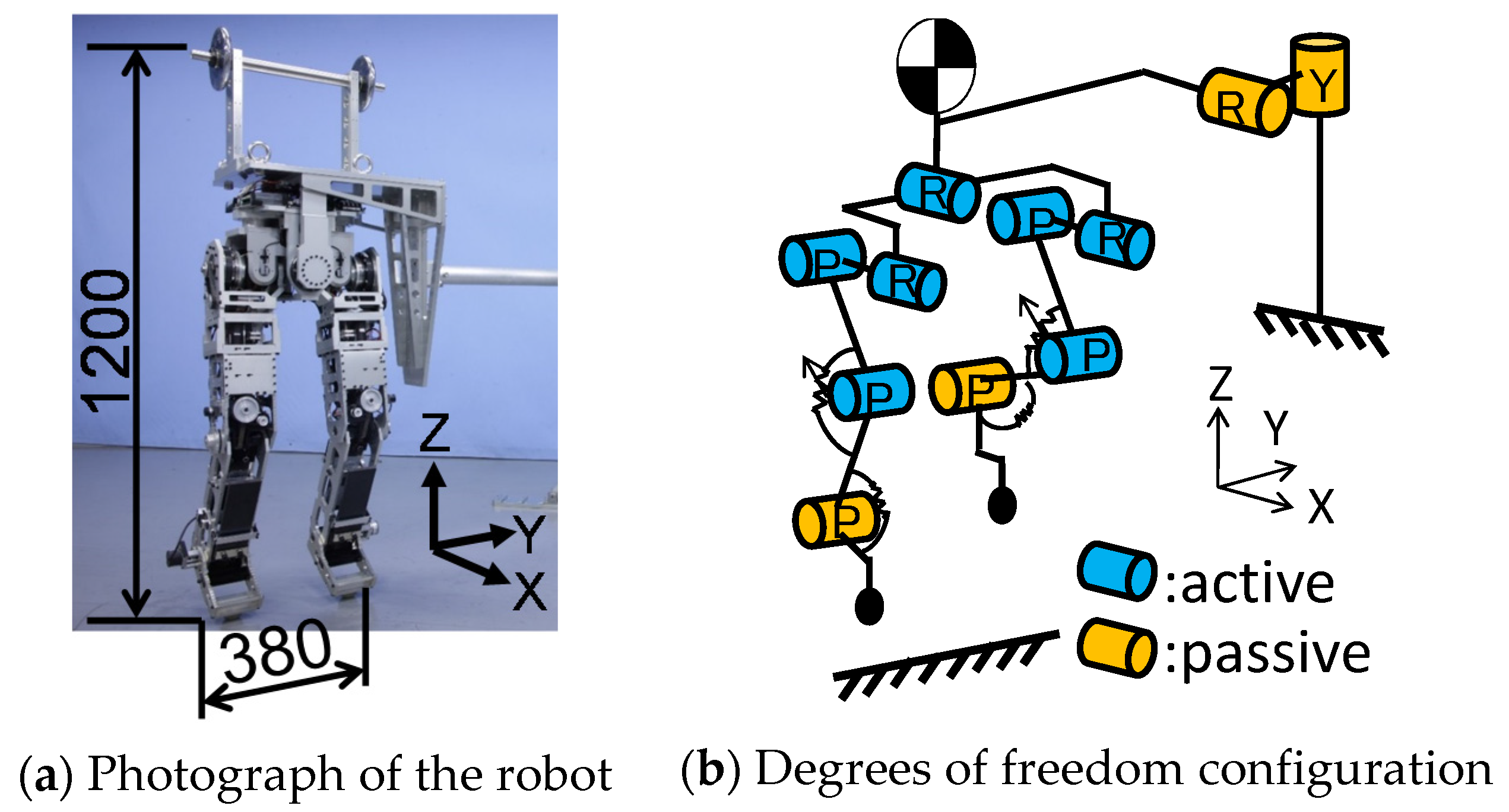
2.5. Implementation of the Joint Mechanism

We designed a robotic leg that incorporates the developed joint mechanism. The developed leg has a knee mechanism comprising two leaf springs, the worm gear and the joint stiffness adjustment mechanism, as well as an ankle comprising two leaf springs. The joint stiffness of the ankle does not vary as widely as that of the knee joint (see Table 1), and the ankle’s range of motion during the swing phase, approximately 30°, is more restricted than that of the knee, approximately 60° [7]. Therefore, in order to keep the mass of the ankle more consistent with the mass of a human ankle, we did not implement the worm gear and the joint stiffness adjustment mechanism in the ankle joint. In the foot, we implemented a rubber hemisphere at the end of each toe for point grounding.
In addition, the developed leg was implemented with a pelvis mechanism (see Figure 7a). We used 150-W DC motors, timing belts and harmonic drives to actuate the pelvis roll joint and hip joints. To perform human-like motions, the robot, which weighs 60 kg, must be approximately the same size as a human [35]. The weight of the robot’s upper body is designed such that the location of the center of mass and the moment of inertia about the center of mass are consistent with those of the human body [36]. The mass of the robot is close to that of a human, and the height is similar to that of a human’s chest. Moreover, the mass of each part of the robot is similar to the mass of the corresponding part of the human body. This was possible because the variable stiffness actuator mechanism was made lighter by using the worm gear and the CFRP-laminated leaf springs. Table 3 describes the configuration of the robot. This robot has nine actuators, can move its pelvis in the same way a human does and can jump because it can store energy via leg elasticity and use it efficiently via resonance based on pelvic oscillation. Robot motion was restricted to the vertical and horizontal directions using a developed guide (see Figure 7b). The guide has two passive joints, and it was connected to the robot’s body to ensure that the robot moves around the guide.
Figure 7. Developed robot used in the experiments.
Machines 04 00005 g007
Table 3. Robot configuration.
Human [29]Robot
Distance between hip joints (mm)180180
Thigh length (mm)374377
Shank length (mm)339339
Foot length (mm)170170
Height of center of the mass (mm)786691
Moment of inertia (kg·m2)6.35.8

3. Experiments and Discussion

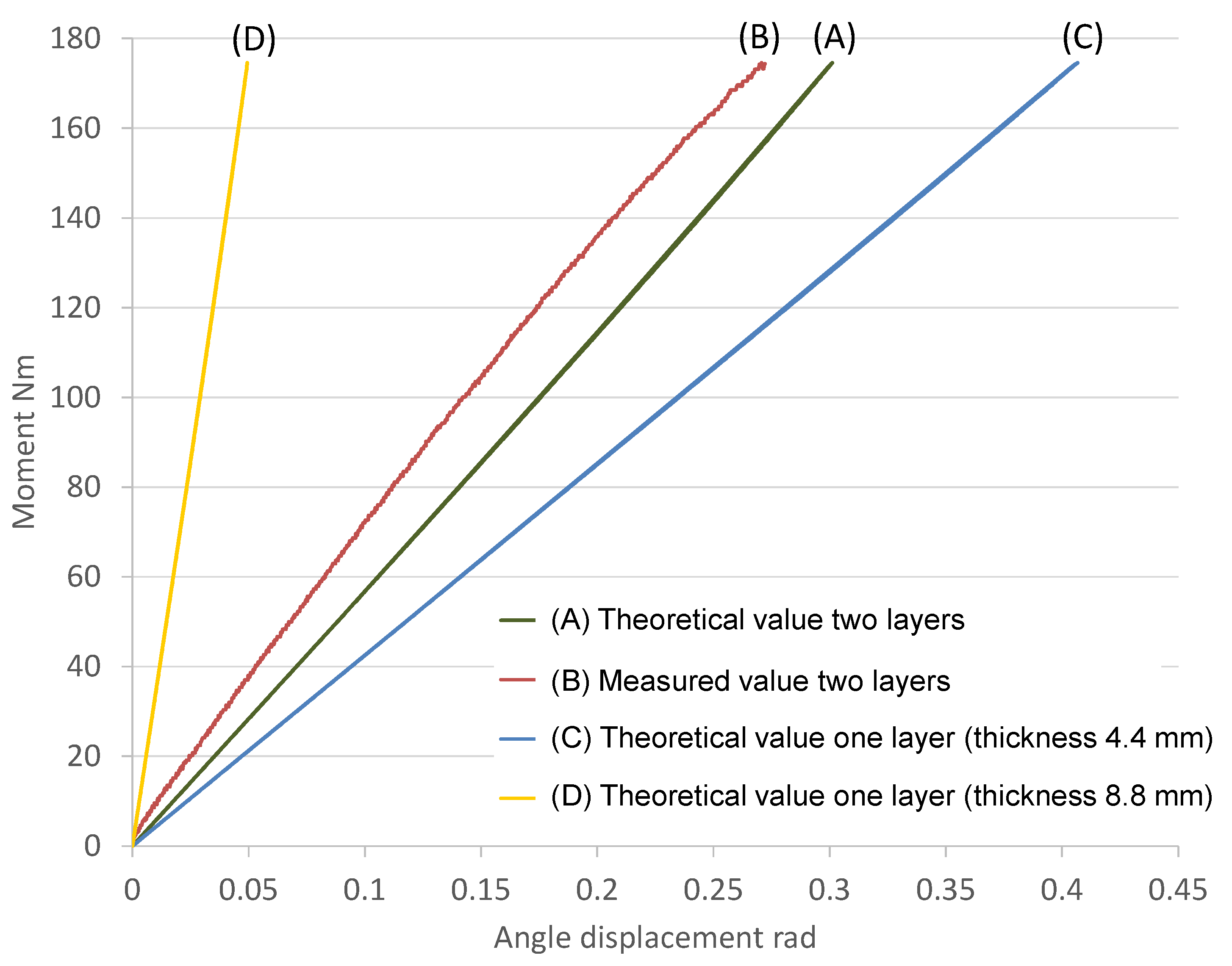
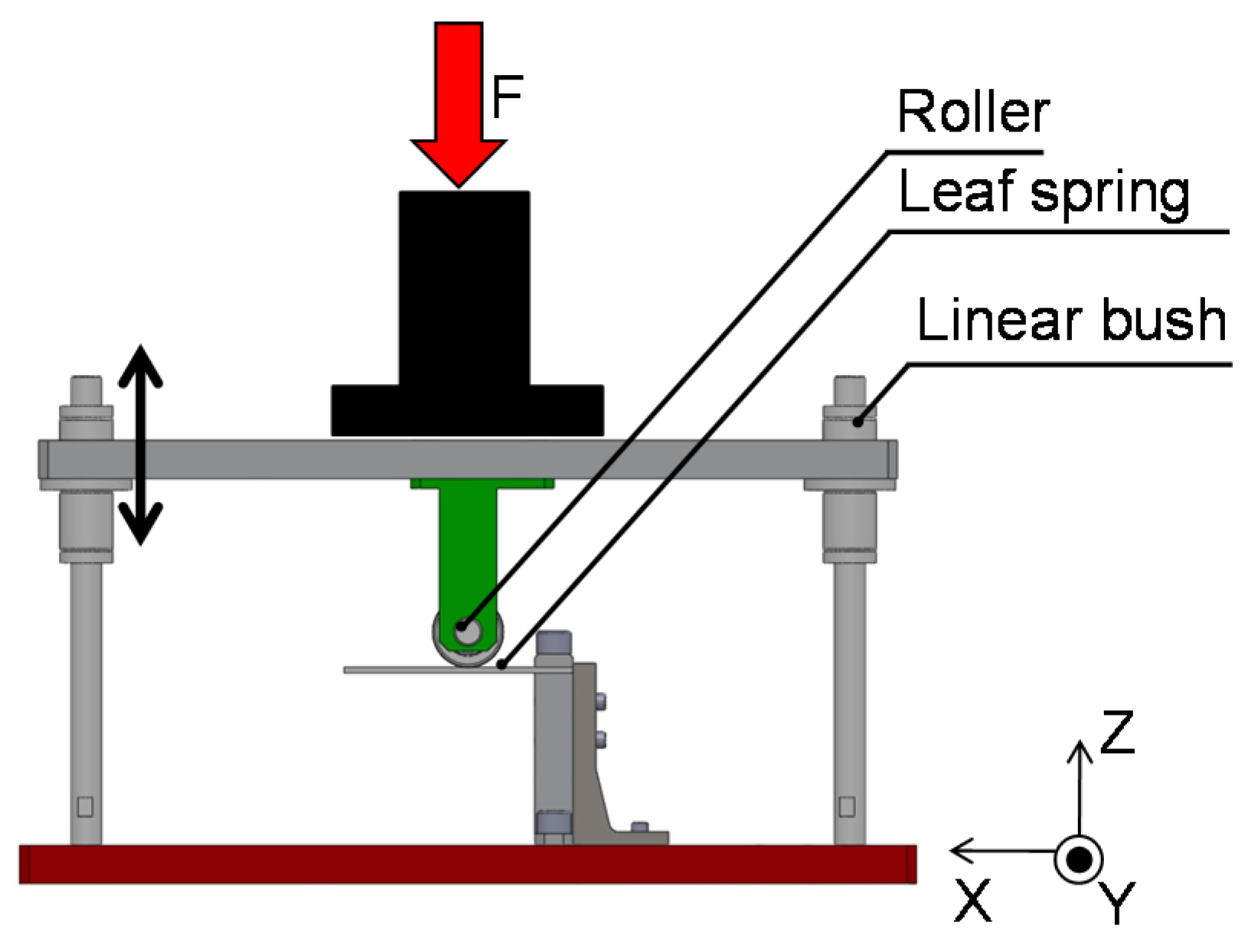
3.1. Verification of the CFRP-Laminated Leaf Spring

To verify the stiffness of the CFRP-laminated leaf spring, we subjected it to a load test. We developed a test fixture for the leaf spring and applied a load in the vertical direction using a load testing machine (see Figure 8). The leaf spring is attached to the lower part of the test fixture, and the upper part of the test fixture can move freely in the vertical direction. When the load testing machine applies a load, the leaf spring is loaded through the upper part of the test fixture. By changing the horizontal position of the lower part of the test fixture, we can change the effective length of the leaf spring. We measured the applied load and the deflection of the leaf spring. To evaluate the loading capacity of the leaf spring, we applied loads as high as 177 Nm, which is the torque applied to a human knee joint during running.
Figure 9 presents experimental results and theoretical values for the deflection of the laminated leaf spring, a single leaf spring from the laminated leaf spring and a single leaf spring that is as thick as the laminated leaf spring. The theoretical values are not included if the leaf spring was not able to withstand the load. As the results show, the laminated leaf spring was able to withstand 177 Nm, and the mean value of the measured stiffness of the laminated leaf spring 650 Nm/rad was close to the theoretical value 610 Nm/rad. It is assumed that the difference between the measured value and the theoretical value is caused by approximating the joint displacement.
The stiffness of the laminated leaf spring was lower than that of the single leaf spring with the thickness equal to the thickness of the laminated leaf spring. With the developed joint mechanism, we can increase the joint stiffness by decreasing the effective length of the leaf spring or decrease the joint stiffness by increasing the effective length. However, we cannot implement a leaf spring that is longer than a human thigh or shank. Thus, the lower joint stiffness offered by the laminated leaf spring is beneficial for the developed joint mechanism. The above discussion confirms that the laminated leaf spring is advantageous in terms of loading capacity and size of the joint mechanism.
Figure 8. Test fixture used to measure the deflection of the leaf springs under applied vertical loads.
Machines 04 00005 g008
Figure 9. Theoretical and measured deflection of leaf springs in relation to the magnitude of the applied vertical load.
Machines 04 00005 g009

3.2. Verification of Joint Stiffness

We conducted an experiment to evaluate the effectiveness of the joint mechanism comprising two laminated leaf springs in mimicking human knee joint stiffness. In this experiment, we made the ankle joint passive in order to exclude any influence from the ankle. The robot was lifted then lowered to apply to the leg a vertical downward force proportional to the mass of the robot. To determine the knee joint stiffness, we measured the knee joint angle using an encoder attached to the knee joint, and we measured the downward force using a force sensor located on the floor. The joint torque was calculated from the knee joint angle displacement, thigh length and downward force. In this experiment, the robotic motion was restricted to the vertical direction using linear guides.
The experimental results are summarized in Table 4. As the results show, the range of the joint stiffness of the developed joint is wider than that of a human knee joint. In addition, the theoretical value was almost the same as the measured value by taking into account the difference between the positions of the fixed point of the leaf spring and the rotational center of the joint mentioned in Section 2.3.
Table 4. Knee joint stiffness evaluation.
Min. (Nm/rad)Max. (Nm/rad)
Requirement for knee joint300600
Theoretical value230690
Measured value230680

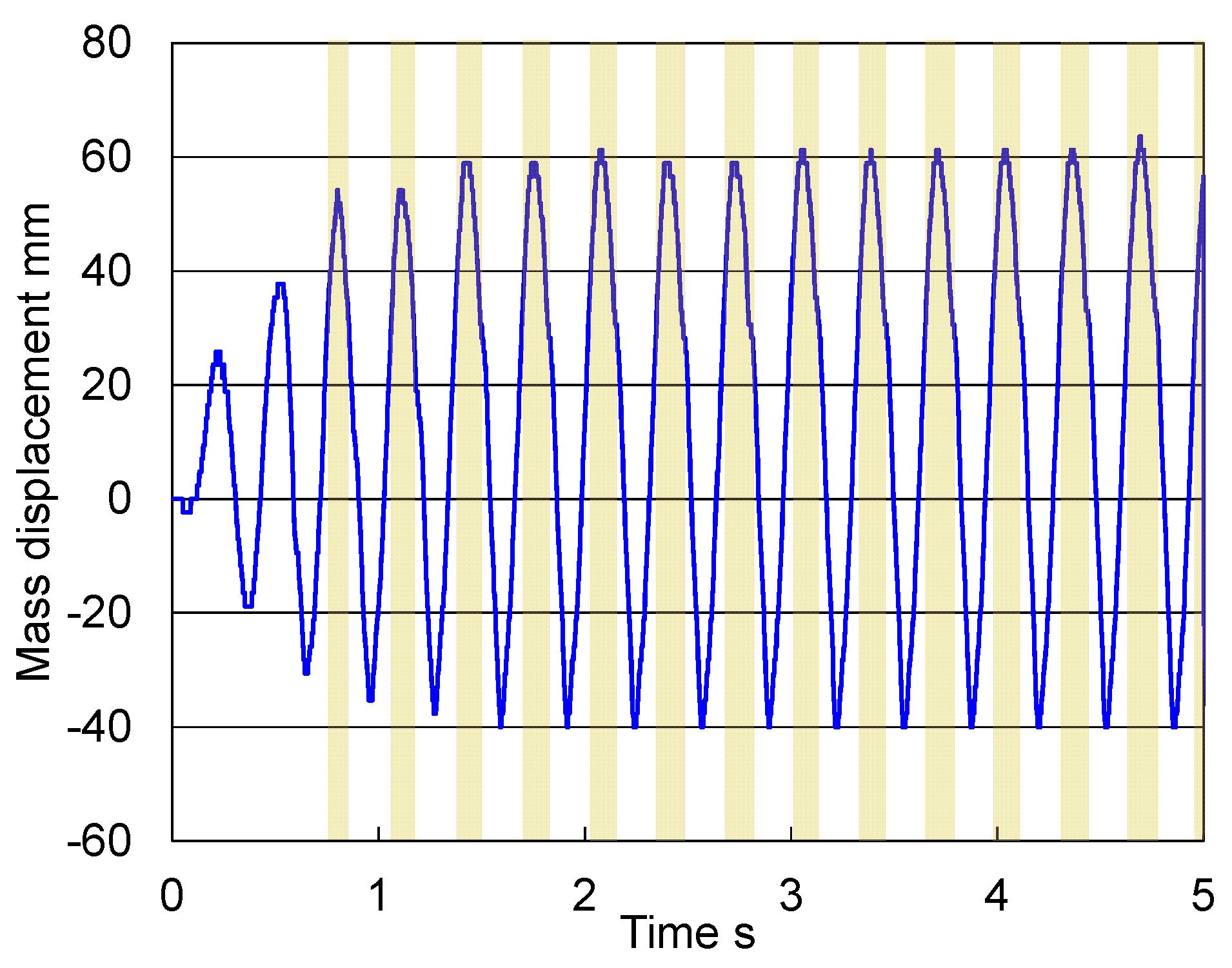
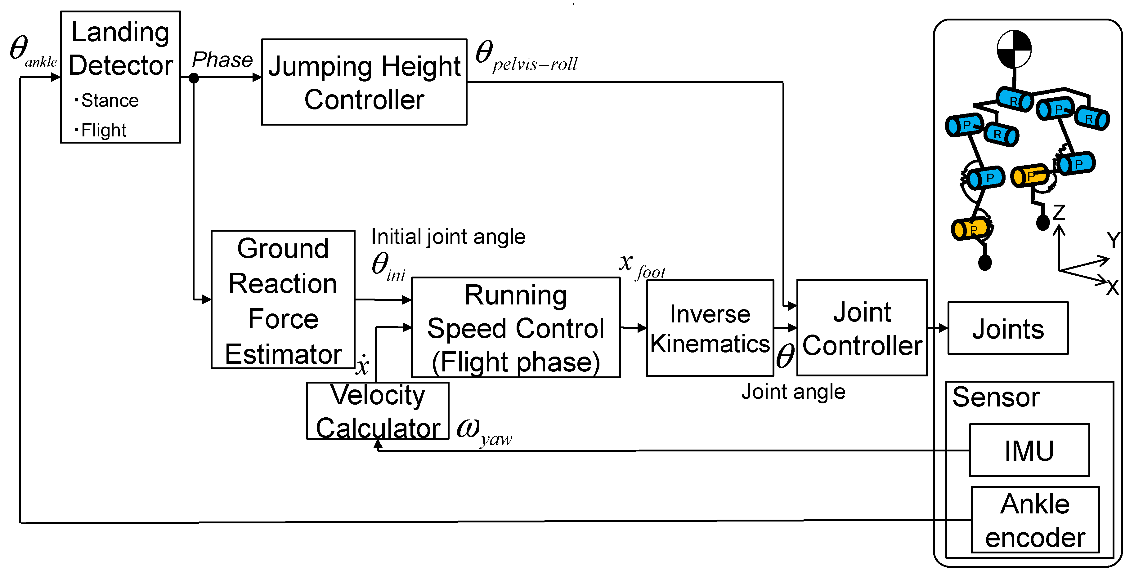
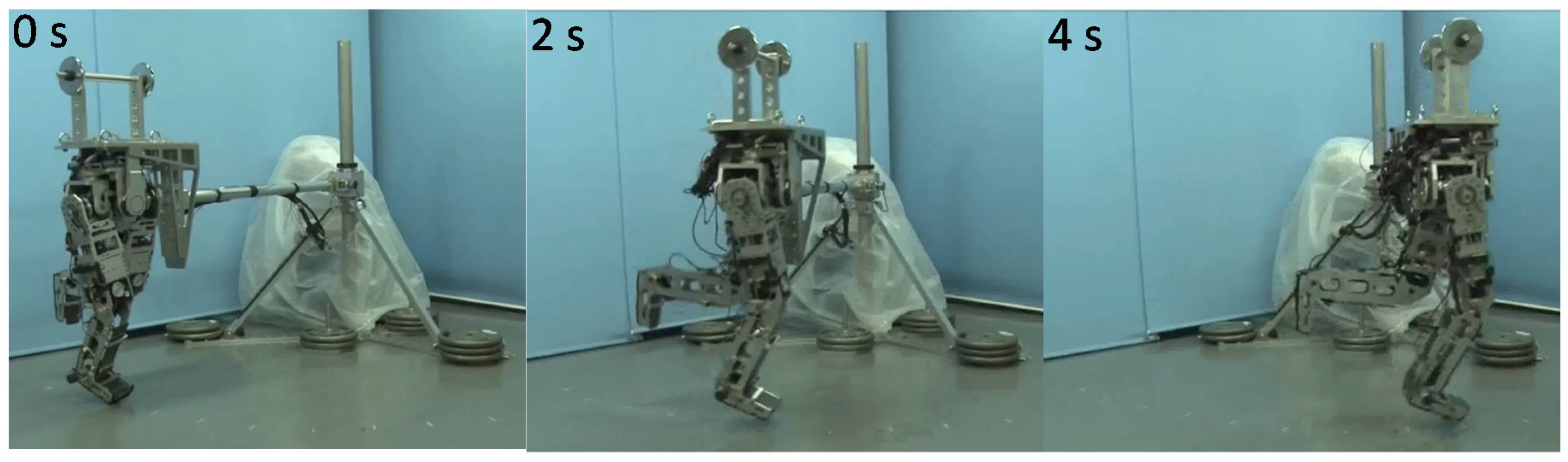
3.3. Hopping Experiment

To confirm that the developed robot can use its joint elasticity for running, we performed a hopping experiment and measured the mass displacement and the flight time, in order to verify that the developed joint can be used to attain jumping power. We previously developed a running control method using the resonance related to pelvic movement and leg elasticity [37], and we used that method in this experiment (Figure 10). The robot moved its pelvis in the stance phase to attain a jumping force with a jumping height controller. Moreover, the robot changed leg joint angles for stabilization with a ground reaction force estimation and controlled the running speed with a running speed controller in the flight phase. The experimental conditions are listed in Table 5. The amplitude of the pelvic oscillation and the joint stiffness were selected based on human running data. In this experiment, the robot initially stood, then started to move its pelvis according to the pelvic oscillation control method. When the robot was able to jump, it moved its pelvis to the landing angle by the next landing and moved its hip pitch joint according to the running speed control method, with a reference running speed of 0.2 m/s. In the running speed control, we used the value of the leg length calculated according to the link length and the joint angles of the leg when the robot landed. The gain for the running speed control was determined experimentally.
Figure 10. Block diagram of the control system in the hopping experiment.
Machines 04 00005 g010
Table 5. Experimental parameters.
Parameter
Whole mass (kg)60
Running speed reference (m/s)0.2
Pelvic oscillation amplitude (°)5
Knee joint stiffness (Nm/rad)220
Ankle joint stiffness (Nm/rad)520
Natural period (s)0.3
Hip angle of stance leg at landing (°)10
Knee angle of stance leg at landing (°)40
Ankle angle of stance leg at landing (°)90
Hip angle of swing leg at landing (°)18
Knee angle of swing leg at landing (°)75
Ankle angle of swing leg at landing (°)90
Figure 11 presents photographs of the running experiment, and Figure 12 depicts the vertical displacement of the center of mass of the robot. In Figure 12, the orange area means that the robot took off the ground. The robot started its pelvic oscillation and started to hop and run after a few oscillations. This indicates that the joint mechanism can withstand the large torque that occurs during the stance phase of running. During the flight phase, the robot used running speed control. Based on experimental results, the time of the stance phase was approximately 270 ms, and the time of the flight phase was approximately 120 ms. The running robot can bend and stretch its knee within 100 ms during the flight phase to achieve alternate bipedal running. The time of the stance phase in human running is approximately 260 ms, and that of the flight phase is approximately 100 ms [7]. The robot’s gait timing was similar to human gait timing. Moreover, the maximum power that the joint mechanism output in the hopping experiment was approximately 1000 W, which is similar to the human data [11,14,15,16]. It is much greater than the ordinary joint mechanisms for humanoids, which can output approximately 150 W at most.
The proposed mechanism would be advantageous if the robot could run at a higher speed. However, this is difficult because of a lack of power in the hip joint. For knee and ankle joints, we achieved high power output by mimicking human joint stiffness. However, it is difficult to achieve high power output in a hip joint by using the developed mechanism, because the hip joint of a human does not move like a spring. We plan to develop a hip joint that can achieve high power output; nevertheless, in this study, we confirmed that the performance of the developed joint fulfills the requirements based on human running data and is adequate for higher speed running in terms of energy storage capacity, maximum output torque, maximum output power, maximum deflection angle, movable range and angular velocity. The specifications of the developed joint mechanism are listed in Table 6.
In this experiment, we implemented some control method, such as the foot placement control, and the ground reaction force estimation, as our previous study [37]. However, to achieve more stable running or running at higher speed, we consider that the upper body movement is needed for stabilization. This is derived from humans, which are considered to use their trunk and arms for stabilization during running [13].
Table 6. Summary of the developed joint mechanism.
Specification
Energy storage capacity (J)73
Maximum torque (Nm)180
Maximum power (W)1000
Maximum deflection angle (rad)0.81
Active movement range (rad)0–1.7
Active movement angular velocity (rad/s)6.7
Figure 11. Photograph of hopping experiment (running speed was 0.2 m/s).
Machines 04 00005 g011
Figure 12. Mass vertical displacement in the hopping experiment.
Machines 04 00005 g012

4. Conclusions and Future Work

Our long-term goal is mimicking human running with a whole body robot. However, this involves various challenging problems, such as power shortage, stabilization, and so on. Therefore, in this paper, we reported the solution of the power shortage by mimicking human joint stiffness. We described the development of a robotic joint that incorporates a joint stiffness adjustment mechanism that uses two laminated leaf springs made of CFRP and a worm gear to mimic the joint stiffness of a human leg, and we incorporated this joint mechanism into the leg of a bipedal robot. With the new mechanism, it is possible to adjust the joint stiffness by changing the effective length of the leaf springs, and the joint stiffness can be calculated using a proposed equation, which takes into account the difference between the positions of the fixed point of the leaf spring and the rotational center of the joint. The CFRP-laminated leaf spring was lighter than an equivalent iron leaf spring. We confirmed the effectiveness of the laminated leaf spring in terms of loading capacity and size, and we verified that the developed joint mechanism can mimic the joint stiffness of a human leg. We also confirmed the effectiveness of a proposed equation for calculating the joint stiffness according to the difference between the positions of the fixed point of the leaf spring and the rotational center of the joint. The developed robot achieved hopping via resonance, which confirms that the developed joint mechanism can be used for storing energy for jumping. This energy-storage mechanism is based on human motion analysis and improves the performance of the robot, and it could be applied also to other humanoid robots or new prosthetic legs. We intend to develop, in the near future, an upper body that will allow us to construct a new full-body running robot that can mimic various characteristics of human running, for example stabilization using the upper body.

Acknowledgments

This study was conducted with the support of the Research Institute for Science and Engineering, Waseda University, the Institute of Advanced Active Aging Research, Waseda University, and as part of the humanoid project at the Humanoid Robotics Institute, Waseda University. It was also supported in part by the MEXT/JSPS KAKENHI Grant Nos. 25220005 and 25709019, the Mizuho Foundation for the Promotion of Sciences, SolidWorks Japan K.K., DYDEN Corporation, Cybernet Systems Co., Ltd., and TohoTenax Co., Ltd. We thank all of them for the financial and technical support provided.

Author Contributions

T.O., K.H., T.I., H.-O.L. and A.T. developed the joint mechanism; T.O., K.H., and T.I. performed the experiments; M.S. and Y.K. analyzed the human motion data; H.-O.L. and A.T. helped to draft the manuscript. T.O. wrote the paper. All authors read and approved the final manuscript.

Conflicts of Interest

The authors declare no conflicts of interest.

References

  1. Ogura, Y.; Shimomura, K.; Kondo, H.; Morishima, A.; Okubo, T.; Momoki, S.; Lim, H.O.; Takanishi, A. Human-like Walking with Knee Stretched, Heel-contact and Toe-off Motion by a Humanoid Robot. In Proceedings of the IEEE/RSJ International Conference on Intelligent Robots and Systems 2006, Beijing, China, 9–15 October 2006; pp. 3976–3981.
  2. Hashimoto, K.; Hattori, K.; Otani, T.; Lim, H.O.; Takanishi, A. Foot Placement Modification for a Biped Humanoid Robot with Narrow Feet. Sci. World J. 2014, 2014, 259570. [Google Scholar] [CrossRef] [PubMed]
  3. Hashimoto, K.; Takezaki, Y.; Lim, H.O.; Takanishi, A. Walking Stabilization Based on Gait Analysis for Biped Humanoid Robot. Adv. Robot. 2013, 27, 541–551. [Google Scholar] [CrossRef]
  4. World Medical Association. Declaration of Helsinki; World Medical Association: Helsinki, Finland, 1964. [Google Scholar]
  5. Blickhan, R. The Spring-mass Model for Running and Hopping. J. Biomech. 1989, 22, 1217–1227. [Google Scholar] [CrossRef]
  6. McMahon, T.; Cheng, G. The Mechanics of Running: How does Stiffness Couple with Speed? J. Biomech. 1990, 23, 65–78. [Google Scholar] [CrossRef]
  7. Novacheck, T.F. The biomechanics of running. Gait Posture 1998, 7, 77–95. [Google Scholar] [CrossRef]
  8. Kuitunen, S.; Komi, P.V.; Kyrolainen, H. Knee and ankle joint stiffness in sprint running. Med. Sci. Sports Exerc. 2002, 34, 166–173. [Google Scholar] [CrossRef] [PubMed]
  9. Gunther, M.; Blickhan, R. Joint stiffness of the ankle and the knee in running. J. Biomech. 2002, 35, 1459–1474. [Google Scholar] [CrossRef]
  10. Ferber, R.; Davis, I.M.; Williams, D.S., III. Gender Differences in Lower Extremity Mechanics during Running. Clin. Biomech. 2003, 18, 350–357. [Google Scholar] [CrossRef]
  11. Chapman, A.E.; Caldwell, G.E. Factors determining changes in lower limb energy during swing in treadmill running. J. Biomech. 1983, 16, 69–77. [Google Scholar] [CrossRef]
  12. Otani, T.; Hashimoto, K.; Yahara, M.; Miyamae, S.; Isomichi, T.; Hanawa, S.; Sakaguchi, M.; Kawakami, Y.; Lim, H.; Takanishi, A. Utilization of Human-Like Pelvic Rotation for Running Robot. Front. Robot. 2015. [Google Scholar] [CrossRef]
  13. Hinrichs, N.R. Upper Extremity Function in Running. II: Angular Momentum Considerations. Int. J. Sport Biomech. 1987, 3, 242–263. [Google Scholar]
  14. Endo, T.; Miyashita, K.; Ogata, M. Kinetics factors of the lower limb joints decelerating running velocity in the last phase of 100 m race. Res. Phys. Educ. 2008, 53, 477–490. [Google Scholar] [CrossRef]
  15. Schache, G.A.; Blanch, D.P.; Dorn, W.T.; Brown, A.T.N.; Rosemond, D.; Pandy, G.M. Effect of Running Speed on Lower Limb Joint Kinetics. Med. Sci. Sports Exerc. 2011, 43, 1260–1271. [Google Scholar] [CrossRef] [PubMed]
  16. Dalleau, G.; Belli, A.; Bourdin, M.; Lacour, J.R. The Spring-Mass Model and the Energy Cost of Treadmill Running. Eur. J. Appl. Physiol. 1998, 77, 257–263. [Google Scholar] [CrossRef] [PubMed]
  17. Nagasaki, T.; Kajita, S.; Kaneko, K.; Yokoi, K.; Tanie, K. A Running Experiment of Humanoid Biped. In Proceedings of the IEEE/RSJ International Conference on Intelligent Robots and Systems, Sendai, Japan, 28 September–2 October 2004; pp. 136–141.
  18. Cho, B.K.; Park, S.S.; Oh, J.H. Controllers for running in the humanoid robot, HUBO. In Proceedings of the IEEE-RAS International Conference on Humanoid Robots 2009, Paris, France, 7–10 December 2009; pp. 385–390.
  19. Takenaka, T.; Matsumoto, T.; Yoshiike, T.; Shirokura, S. Running Gait Generation for Biped Robot with Horizontal Force Limit. JRSJ 2011, 29, 93–100. [Google Scholar] [CrossRef]
  20. Tajima, R.; Honda, D.; Suga, K. Fast Running Experiments Involving a Humanoid Robot. In Proceedings of the IEEE International Conference on Robotics and Automation, Kobe, Japan, 12–17 May 2009; pp. 1571–1576.
  21. Tamada, T.; Ikarashi, W.; Yoneyama, D.; Tanaka, K.; Yamakawa, Y.; Senoo, T.; Ishikawa, M. High Speed Bipedal Robot Running Using High Speed Visual Feedback. In Proceedings of the 14th IEEE-RAS International Conference on Humanoid Robots, Madrid, Spain, 18–20 November 2014; pp. 140–145.
  22. Niiyama, R.; Nishikawa, S.; Kuniyoshi, Y. Biomechanical Approach to Open-loop Bipedal Running with a Musculoskeletal Athlete Robot. Adv. Robot. 2012, 26, 383–398. [Google Scholar] [CrossRef]
  23. Grizzle, J.W.; Hurst, J.; Morris, B.; Park, H.W.; Sreenath, K. MABEL, a new robotic bipedal walker and runner. In Proceedings of the American Control Conference, St. Louis, MO, USA, 10–12 June 2009; pp. 2030–2036.
  24. Tsagarakis, N.G.; Laffranchi, M.; Vanderborght, B.; Caldwell, D.G. A compact soft actuator unit for small scale human friendly robots. In Proceedings of the IEEE International Conference on Robotics and Automation, Kobe, Japan, 12–17 May 2009; pp. 4356–4362.
  25. Ugurlu, B.; Saglia, J.A.; Tsagarakis, N.G.; Caldwell, D.G. Hopping at the resonance frequency: A trajectory generation technique for bipedal robots with elastic joints. In Proceedings of the IEEE International Conference on Robotics and Automation, Saint Paul, MN, USA, 14–18 May 2012; pp. 1436–1443.
  26. Moro, F.L.; Tsagarakis, N.G.; Caldwell, D.G. Walking in the Resonance with the COMAN Robot with Trajectories based on Human Kinematic Motion Primitives (kMPs). Auton. Robots 2014, 36, 331–347. [Google Scholar] [CrossRef]
  27. Vu, H.Q.; Yu, X.; Iida, F.; Pfeifer, R. Improving energy efficiency of hopping locomotion by using a variable stiffness actuator. IEEE/ASME Trans. Mechatron. 2015. [Google Scholar] [CrossRef]
  28. Renjewski, D.; Seyfarth, A.; Manoonpong, P.; Wörgötter, F. The development of a biomechanical leg system and its neural control. In Proceedings of the 2009 International Conference on Robotics and Biomimetics, Guangxi, China, 19–23 December 2009; pp. 1894–1899.
  29. Grimmer, M. Powered Lower Limb Prostheses. Ph.D. Thesis, Technische Universitaet Darmstadt, Darmstadt, Germany, 2015. [Google Scholar]
  30. Yuan, K.; Zhu, J.; Wang, Q.; Wang, L. Finite-state control of powered below-knee prosthesis with ankle and toe. In Proceedings of the 18th IFAC World Congress, Milano, Italy, 28 August–2 September 2011; pp. 2865–2870.
  31. Waycaster, G.; Wu, S.K.; Xiangrong, S. Design and control of a pneumatic artificial muscle actuated above-knee prosthesis. J. Med. Devices 2011, 5. [Google Scholar] [CrossRef]
  32. Hitt, J.; Sugar, T.; Holgate, M.; Bellman, R. An active foot-ankle prosthesis with biomechanical energy regeneration. J. Med. Devices 2010, 4. [Google Scholar] [CrossRef]
  33. Morita, T.; Sugano, S. Development of 4-DOF manipulator using mechanical impedance adjuster. In Proceedings of the IEEE International Conference on Robotics and Automation, Minneapolis, MN, USA, 22–28 April 1996; pp. 2902–2907.
  34. Merritt, H.E. Worm gear performance. Proc. Inst. Mech. Eng. 1982, 129, 127–194. [Google Scholar] [CrossRef]
  35. Kouchi, M.; Mochimaru, M. Human Dimension Database; AIST Digital Human Research Center: Tokyo, Japan, 2005. [Google Scholar]
  36. Ae, M.; Tang, H.; Yokoi, T. Estimation of inertia properties of the body segments in japanese athletes. Soc. Biomech. 1992, 11, 23–33. [Google Scholar]
  37. Otani, T.; Hashimoto, K.; Yahara, M.; Miyamae, S.; Isomichi, T.; Sakaguchi, M.; Kawakami, Y.; Lim, H.O.; Takanishi, A. Running with Lower-Body Robot That Mimics Joint Stiffness of Humans. In Proceedings of the IEEE/RSJ International Conference on Intelligent Robots and Systems, Hamburg, Germany, 28 September–2 October 2015.

