1. Introduction
With the advancement of robotics, interdisciplinary research has been widely conducted to explore effective approaches for improving robot performance to satisfy operational requirements in diverse tasks and environments [
1,
2,
3,
4]. In complex and hazardous mobile environments, the robot is required to perform autonomous obstacle avoidance when encountering obstacle-cluttered terrains, so as to reduce the risk of collision [
5,
6]. Compared with serial mechanisms, parallel mechanisms feature no accumulated positioning errors. However, they are restricted by relatively limited workspace and the occurrence of singular configurations. In terms of actuation modes, parallel mechanisms are categorized into non-redundant actuation and redundant actuation. A parallel mechanism adopts non-redundant actuation when the number of actuators equals the degrees of freedom (DOFs) of its end-effector. By contrast, redundant actuation means that the total number of actuators exceeds the system’s inherent DOFs [
7,
8,
9]. Adding redundant actuated joints can effectively suppress singular configurations of parallel mechanisms and accordingly expand their effective workspace. In addition, optimizing the force distribution among actuators helps enhance the overall actuation performance of parallel mechanisms.
Extensive research on redundant actuation has been conducted by numerous scholars. Feng and Han et al. [
10,
11] developed a redundantly actuated parallel robot with a 2-RRR parallel mechanism. Servo motors were adopted for positional joints and pneumatic cylinders for redundant joints. A cross-coupling-based force–position cooperative control method was proposed to address the actuation coupling issue. Wen et al. [
12,
13] presented a 6PUS-2HKP redundantly actuated parallel robot for mastication, which consists of six PUS driving limbs and two point-contact higher pair constraints. This robot has six actuators for four degrees of freedom (DOFs), thus featuring redundant actuation. A torque optimization-based force/position hybrid control (OTDFP) was proposed to resolve the unbalanced driving force. Experimental results demonstrated that this control scheme reduces joint torque fluctuation, accurately reproduces mastication trajectories and bite forces, and improves the dynamic stability of the system. Wen et al. [
14,
15,
16] designed a 5-DOF parallel mechanism with a 6PUS/UPU configuration, which is composed of six PUS driving limbs and one UPU constraint limb with inherent actuation redundancy and inter-limb coupling. Adopting a hierarchical position–force framework, they proposed a hybrid control strategy combining two-degree-of-freedom fractional-order internal model position control and fuzzy fractional-order force control to improve the accuracy of position tracking and force output, respectively. Nevertheless, the above-mentioned studies are limited to passive internal force distribution and local force–position coordination of single-platform redundantly driven mechanisms.
Sakurai and Shikata et al. [
17,
18,
19,
20] carried out a series of control studies on redundantly actuated parallel robots. They successively investigated singularity-free parallel robots, planar parallel mechanisms, and cable-driven redundant parallel mechanisms. A mode-space-based force/position hybrid control method was developed, where disturbance observers were employed to suppress external disturbances, achieving high-precision trajectory tracking and direct internal force regulation. Experimental validations proved that the proposed method yields lower trajectory errors and stronger anti-disturbance capability, and effectively enhances the motion accuracy and stability of parallel robots. Xi et al. [
21] proposed a single-DOF redundant parallel mechanism and adopted a velocity–force-coordinated control strategy. Closed-loop kinematic and static models were established, and the mapping relationship between force and velocity was derived. A PI controller was utilized to coordinate the load distribution and motion of dual actuators, so as to suppress force conflict and motion mismatch. Zhang et al. [
22,
23,
24,
25] proposed a 2RPU-2SPR redundant parallel mechanism. They adopted computed torque control and force/position hybrid control successively. An adaptive reaching law was introduced to mitigate chattering. In the implemented force/position hybrid control, position closed-loop control was applied to non-redundant limbs and force closed-loop control to redundant limbs, which optimizes the distribution of driving forces. Most of these studies are confined to fixed-base parallel mechanisms. Their corresponding control strategies still exhibit deficiencies in scalability and generality, and few works investigate problems such as multi-body coupled dynamics in multi-mobile-platform systems.
Huang et al. [
26,
27] designed a 6RSS parallel robot for mastication. Considering the requirements of pose–force coordination during mastication, a joint-space impedance control strategy was put forward. Yan et al. [
28,
29,
30] focused on redundant manipulators and proposed several control strategies, including cerebellar-inspired model predictive control, data-driven control, and neurodynamic control. Improved obstacle avoidance constraints were designed, and a neurodynamic solver was used to handle optimization problems. Meanwhile, a discrete Jacobian update law was established to realize model-free adaptive control. Xing and Ding et al. [
31,
32,
33,
34,
35,
36] conducted systematic research on wheeled mobile redundant manipulators. The weighted Jacobian method was used for motion distribution to prioritize the operation of the manipulator. A hierarchical internal model control framework was constructed, and nonlinear disturbance observers were adopted to estimate interaction forces and realize compliant behavior. In addition, cerebellar-inspired and neurodynamic model predictive control were introduced to enhance trajectory tracking and obstacle avoidance performance. Experimental results verified that these control strategies can significantly improve the motion accuracy, force output performance, and teleoperation stability of the system. Ren, Xu, and Zhang [
37,
38,
39] performed a series of control investigations on 2R1T redundant parallel mechanisms. Their control schemes mainly rely on time delay estimation (TDE), sliding mode control, and force/position hybrid control. A TDE-based integral terminal sliding mode control (TDE-ITSMC) was proposed for robust decoupling to compensate for model uncertainties. Most of the above-mentioned investigations focus on control-strategy analysis for fixed scenarios. The majority of these methods mainly address the control of a single redundantly driven unit within a mechanism. Limited research has been conducted on the coordination among multiple redundant drives. Moreover, the coupling effects among numerous joints are frequently neglected, and passive distribution is mostly adopted for closed-loop internal forces without active regulation mechanisms.
A typical characteristic of redundantly actuated mechanisms is that the number of linearly independent actuators exceeds the system degrees of freedom [
40,
41,
42], and strong coupling exists among driving joints. For mobile robots operating in special underground environments, it is necessary to consider not only the coupling among driving forces but also the position requirements imposed by the working environment. To tackle the above issues, this paper proposes a novel force/position hybrid control strategy based on the synergistic integration concept.
The remainder of this paper is organized as follows.
Section 2 presents the kinematic analysis of the mobile robot.
Section 3 establishes and verifies the dynamic model, which lays a theoretical foundation for the subsequent controller design.
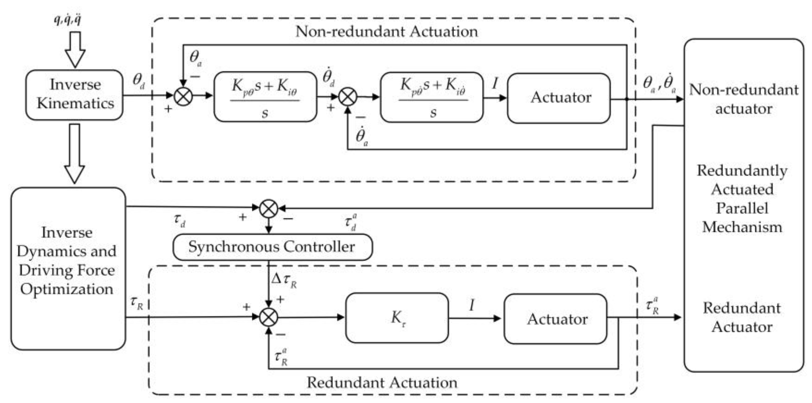
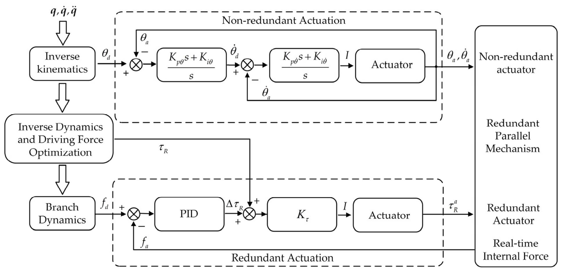
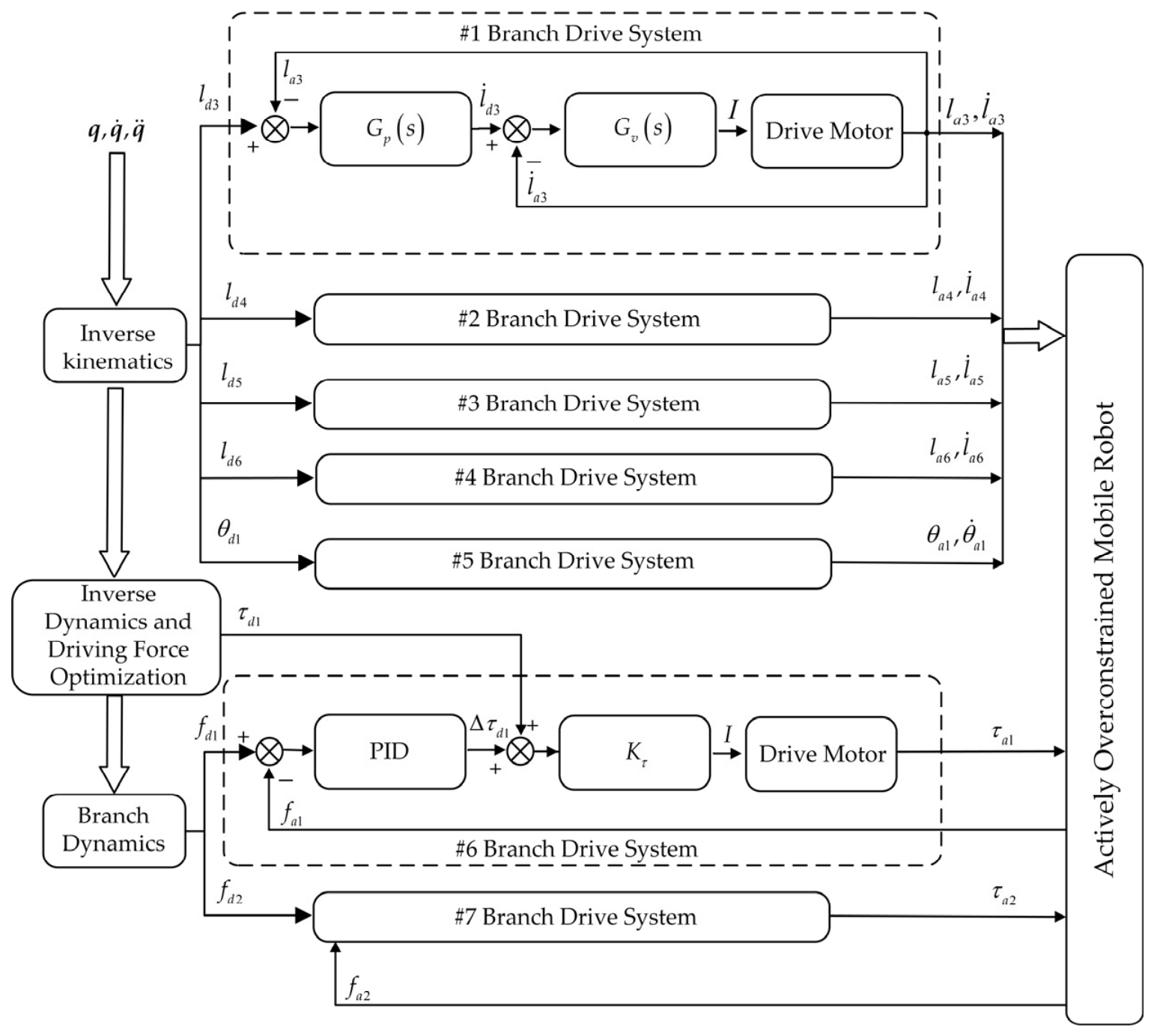
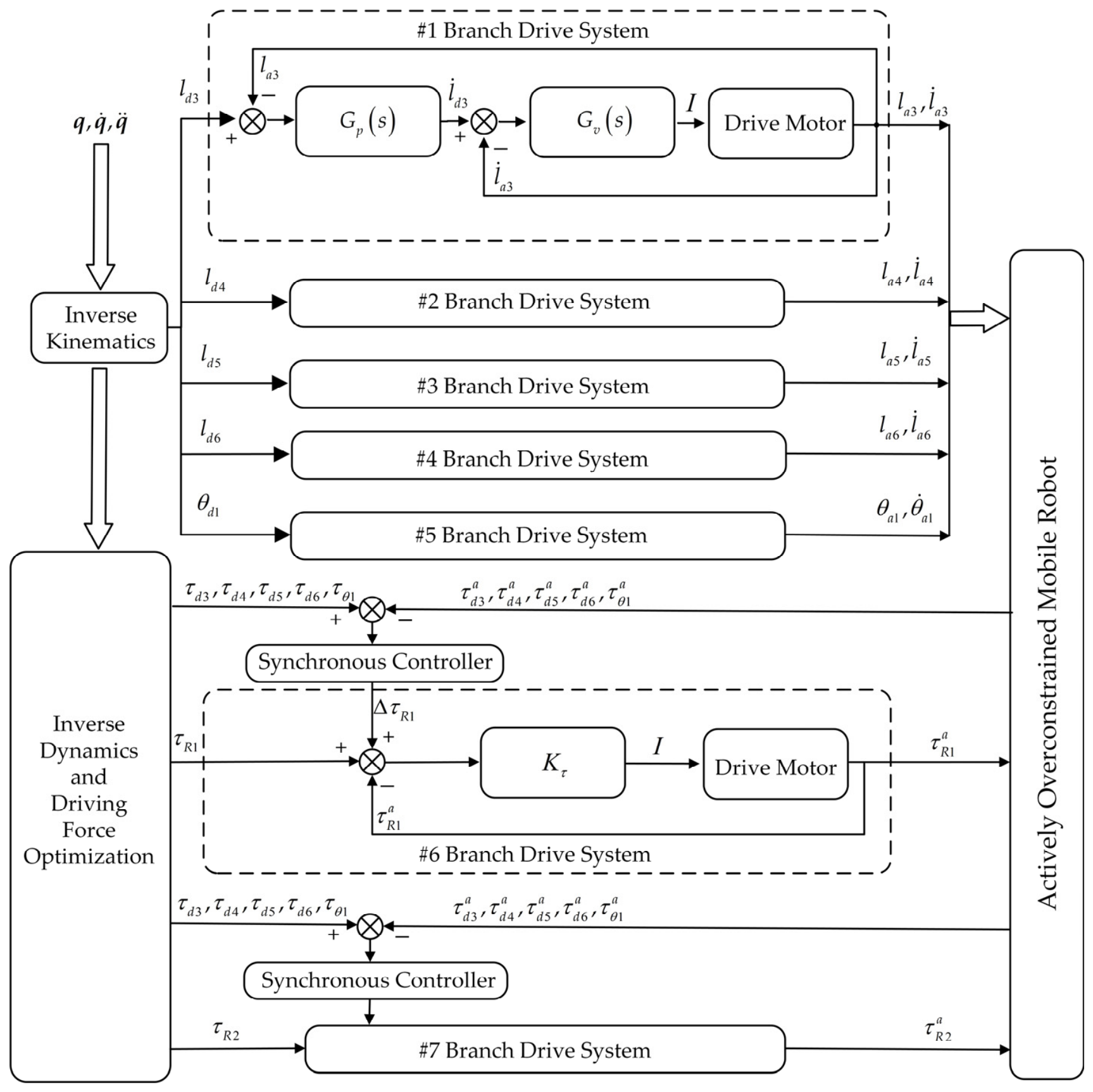
Section 4 develops two control strategies for the three-platform parallel mobile robot. In
Section 5, neural networks are adopted to optimize the active internal force control strategy and synchronous coordination control strategy.
Section 6 conducts comparative physical simulation tests to evaluate the performance of the two original strategies and their neural network-based optimized versions, thereby verifying the effectiveness of the proposed methods. Finally,
Section 7 summarizes the main conclusions of this work and outlines the prospects for future research.
2. Kinematic Analysis of the Three-Platform Parallel-Coupled Mobile Robot
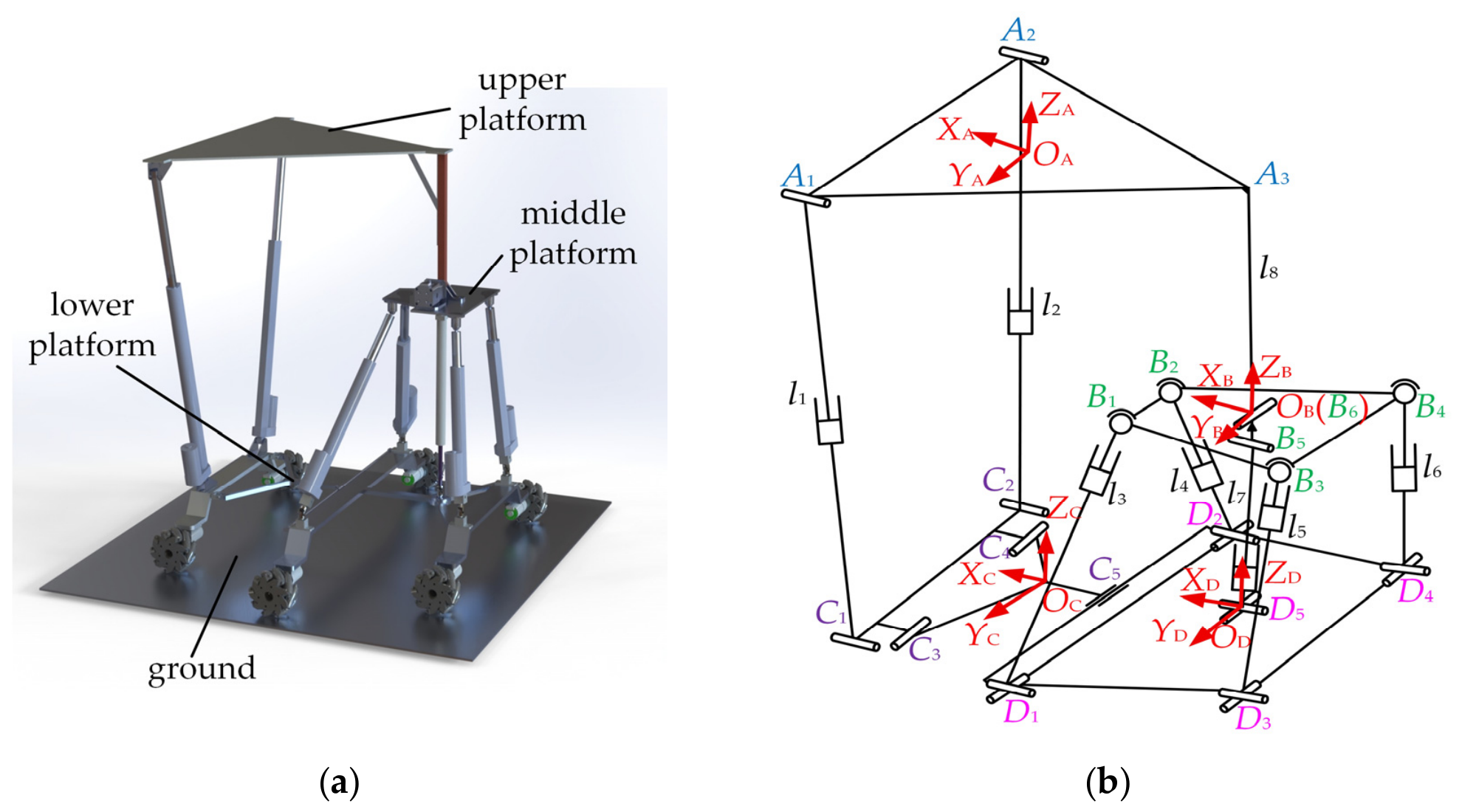
This paper innovatively proposes a three-platform parallel robot. Adopting symmetric structural features, the robot platforms are designed based on the parallelogram rule, and its lower platform is configured as a symmetric foldable-deployable mechanism [
43]. The detailed structure is illustrated in
Figure 1a. The upper platform is an equilateral triangular loading platform located at the top of the robot. The base corners of the upper triangular platform are connected to the front bracket via two RPR limbs, while its vertex is linked to the middle platform through an R-joint limb.
To avoid collision between the two front RPR limbs and the middle platform during motion, the middle platform is designed as an isosceles trapezoid with a shorter upper base. The revolute joint of the R-joint limb is mounted at the center of the trapezoidal middle platform, and the other end is rigidly connected to the upper platform. The middle platform is connected to the middle bracket and rear bracket by four UPS limbs, and coupled with the second herringbone link via one UPR limb, as illustrated in the figure. To improve the overall stability of the robot, the middle bracket is designed to be longer than the front and rear brackets, where the front and rear brackets have identical dimensions. Mecanum wheels are installed at both ends of the front, middle, and rear brackets.
The first herringbone link is connected to the front bracket by two revolute joints and to the middle bracket by one cylindrical joint. The second herringbone link is fixedly integrated with the middle and rear brackets. For structural analysis simplification, the lower platform is divided into Lower Platform I and Lower Platform II. Lower Platform I consists of the front bracket and the first herringbone link, and Lower Platform II is composed of the middle bracket, the second herringbone link, and the rear bracket. Herein, the parallel mechanism formed by the middle platform, Lower Platform II, four UPS limbs, and one UPR limb is defined as the sub-parallel mechanism.
To facilitate the analysis of locomotion performance of the mobile robot, its schematic diagram is drawn as shown in
Figure 1b. The left side of the diagram indicates the forward direction of the robot. Coordinate systems are established on different moving platforms in the schematic. Kinematic pairs are mounted on each platform with their centerlines arranged on the same plane. Accordingly, the gaps between kinematic pairs and platforms are neglected in the spatial coordinate analysis. As illustrated in
Figure 1b, the upper platform is an equilateral triangle denoted by
A1A2A3. The middle platform consists of four spherical joints forming an isosceles trapezoid
B1B2B3B4. The lower platform is designed with deformable and foldable structures, which is composed of a front bracket, a middle bracket, a rear bracket, the first herringbone link, and the second herringbone link. The assembly of the front bracket and the first herringbone link is defined as Platform I, represented by
C1C2D1D2. The combination of the middle bracket, the rear bracket, and the second herringbone link is defined as Platform II, denoted by
D1D2D3D4. The front bracket and the rear bracket share an identical structure. To guarantee the stability of the mobile robot, the middle bracket is designed with a larger dimension. The geometric relationship satisfies
D1D2 >
C1C2 =
D3D4.
Coordinate systems
OA-
XAYAZA,
OB-
XBYBZB,
OC-
XCYCZC, and
OD-
XDYDZ
D are established on the upper platform, middle platform, Lower Platform I, and Lower Platform II, respectively. The origins of the four coordinate systems are located at the geometric centers of the corresponding platforms. The
X-axis of each coordinate system points along the forward direction of the wheeled-legged robot, and the
Z-axis points vertically upward. The direction of the
Y-axis is determined by the right-hand rule. Marked as
A1 and
A2 in the figure, two revolute joints are mounted on the upper platform, and their rotational axes are aligned with the
XA-axis of
OA-
XAYAZA. The upper platform is rigidly connected to the link of the R-joint at point
A3. On the middle platform, points
B1–4 denote four spherical joints.
B5 and
B6 are two revolute joints with mutually perpendicular axes, which are arranged at the center of the lower and upper surfaces of the middle platform, respectively. The rotational axis of joint
B5 coincides with the
XB-axis of
OB-
XBYBZB, while the axis of joint
B6 is parallel to the
YB-axis. The link between the upper platform and the middle platform is denoted as
A3B6. For Lower Platform I, there are four kinematic joints labeled
C1–4. Among them,
C1 and
C2 are revolute joints whose rotational axes are parallel to those of
A1 and
A2. The rotational axes of
C3 and
C4 are parallel to the
YC-axis of
OC-
XCYCZC. In
Figure 1b,
C1 and
C3, and
C2 and
C4 are drawn in a staggered layout for visual distinction, whereas they are actually arranged in the front–rear direction. The spacing between them can be neglected in numerical calculations.
C5 represents a cylindrical joint that connects Lower Platform I and Lower Platform II, and its axis is parallel to the axes of
C3 and
C4. Lower Platform II is equipped with five kinematic joints
D1–5, all of which are universal joints. One rotational axis of each universal joint is parallel to the
YD-axis of
OD-
XDYDZD. Key structural parameters of the schematic are defined hereinafter. The connections of
A1C1,
A2C2,
B1D1,
B2D2,
B3D3,
B4D4, and
B5D5 are realized via prismatic joints, and the lengths of these seven links are defined as
l1–7 correspondingly. The rigid link
A3B6 has a constant length denoted by
l8. Lower Platform I and Lower Platform II are congruent isosceles trapezoids, with the short side, long side and height defined as
a1,
b1 and
k1, respectively. For the middle platform, the short side, long side, and height are denoted as
a2,
b2, and
k2. The upper platform is an equilateral triangle, whose side length and height are represented by
a3 and
k3.
The inverse kinematics analysis of the mobile robot refers to the inverse kinematic solution of its parallel mechanism. Given the pose parameters (x, y, z, α, β, γ) of the moving platform in space, the inverse kinematics aims to calculate the linear or angular displacements of the actuators. These six parameters represent the translational motions along three coordinate axes and rotational motions about the corresponding axes in the coordinate system established on the fixed platform.
Let the pose of the middle platform coordinate system relative to the coordinate system of Lower Platform II be defined as (
x1,
y1,
z1,
α1,
β1,
γ1). The variable
x1 is not an active displacement but a passive motion induced by other movements. Rotation about the
XD-axis has no effect on
x1, which yields
x1 =
z1tan
β1. In addition, no rotation occurs about the
ZD-axis, so
γ1 = 0. Referring to the schematic diagram of the mobile robot in
Figure 1b, the prismatic joints of the four UPS limbs are selected as actuators. The lengths of the corresponding four links are denoted by
li(
i = 3, 4, 5, 6), namely
B1D1 =
l3,
B2D2 =
l4,
B3D3 =
l5 and
B4D4 =
l6. The middle platform, Lower Platform I and Lower Platform II are all isosceles trapezoids, and Lower Platform I is congruent to Lower Platform II. All geometric dimensions are defined based on the joints connecting the limbs. The upper platform is an equilateral triangle. Accordingly, the equation for calculating the height
k3 of this equilateral upper platform can be derived.
Accordingly, the side length of the equilateral triangular moving platform, denoted by
a3, can be derived as follows. To simplify the calculation, let
λi represent the ratio of the distance from the geometric center of the isosceles trapezoid to its long side to the total height of the trapezoid. The corresponding equations are obtained as below.
As shown in
Figure 1b, four coordinate systems are established for the mobile robot. The coordinates of two endpoints of each link in the coordinate system of Lower Platform II can be determined. The coordinates of each point on the middle platform in the coordinate system
OD-
XDYDZD can be expressed as:
where
P1 denotes the spatial position vector of the origin of the middle platform coordinate system with respect to the coordinate system
OD-
XDYDZD, i.e.,
P1 = [
x1 y1 z1]
T.
T1 is the coordinate transformation matrix obtained under the
X-
Y-
Z Euler-angle mode for degrees of freedom. Accordingly, the coordinates of points in the coordinate system
OB-
XBYBZB can be derived in
OD-
XDYDZD. Similarly, the coordinates of points belonging to the coordinate system
OA-
XAYAZA can also be expressed in
OD-
XDYDZD. On this basis, the lengths of all links are calculated via the closed-loop vector method, and the inverse kinematic solutions are further obtained.
For the upper platform analysis, its pose relative to the coordinate system of Lower Platform II is defined as (x2, y2, z2, α2, β2, γ2). Since no rotation about the ZD-axis exists for the upper platform, we have γ2 = 0. The pose of the upper platform is mainly determined by the rotation angle of the revolute joint on the R-joint link. The rotational angle of the upper platform coordinate system about the YB-axis with respect to the middle platform coordinate system is defined as θ1, which equals the rotation angle of the aforementioned revolute joint.
Since
x1 =
z1tan
β1, the value of
β1 can be solved. The rotation angles of the upper platform and the middle platform about the
XD-axis are identical, namely
α1 =
α2.
The rotation angle
β2 of the upper platform coordinate system about the
YD-axis equals the sum of
β1 (the rotation angle of the middle platform coordinate system about the
YD-axis) and
θ1 (the rotation angle of the revolute joint on the R-joint link).
With the aid of the closed-loop vector method, the linear displacements of the prismatic joints in the two RPR limbs connecting the upper platform and Lower Platform I can be calculated.
In summary, Equations (4), (6) and (7) constitute the inverse kinematic solutions of the three-platform parallel mobile robot.
3. Dynamic Modeling of the Three-Platform Parallel-Coupled Robot
With the advancement of robotics, interdisciplinary research has been conducted to explore effective approaches for improving robot performance to meet operational requirements in diverse tasks and environments. As a national strategic development direction in China, “Coexisting-Cooperative-Cognitive” (Tri-Co) Collaboration has attracted widespread attention. A Tri-Co robot can adapt to environments and perform collaborative operations through real-time interaction with working conditions and environments, as well as information exchange between operators and robots [
44,
45]. Its core characteristics lie in superior adaptability to complex and unstructured dynamic environments, good perception of human operating behaviors, and the capability to realize human–robot and robot–robot collaboration within specified rules. Reconfigurable robots can adjust their configurations and postures according to various tasks, thus enhancing their trafficability in complex scenarios. The three-platform parallel robot studied in this work is designed for complex underground environments, and it needs to fulfill multiple functions, including mutual constraint, cooperative operation, and autonomous perception among the three platforms and connecting links. In terms of structure, the upper platform and its connecting links with the sub-parallel mechanism form an independent unit, while the sub-parallel mechanism composed of the middle and lower platforms serves as another separate unit, which constitutes an internal collaboration mechanism. Since the robot operates in intricate underground environments and requires continuous information interaction with the surroundings, it is of great significance to investigate Tri-Co Collaboration for the proposed three-platform parallel-coupled mobile robot.
Prior to dynamic analysis of redundantly actuated parallel mechanisms, an appropriate dynamic model needs to be established. Such mechanisms are featured with more actuators than system degrees of freedom. At present, multiple methods are available for dynamic modeling of parallel mechanisms. These methods differ in solution procedures and model forms, yet they yield identical results for driving forces. In this paper, the principle of virtual work is adopted for dynamic modeling, due to its clear derivation process and definite physical meaning. To simplify the calculation, the frictional effects between components are neglected during model establishment.
3.1. Dynamic Modeling of Non-Redundantly Actuated Robots
The frictional forces at joints between all components are neglected. The motion of the non-redundantly actuated mobile robot is mainly affected by inertial forces, gravity, external loads, and driving forces generated by actuators. Under the non-redundant control mode, the driving vector of the robot is expressed as
The independent pose parameters of the upper platform relative to Lower Platform II (the fixed platform) are given as follows.
In the above formula,
x2,
y2 and
z2 denote the position coordinates of the origin
OA of the upper platform coordinate system in
OD-
XDYDZD established on the fixed platform (Lower Platform II).
α2 and
β2 represent the rotation angles of the upper platform about the
XD-axis and
YD-axis of the fixed platform coordinate system, respectively. Since no rotation about the
ZD-axis occurs between the upper platform and the fixed platform,
γ2 = 0. Under this condition, the pose of the middle platform relative to the fixed platform can be solved via inverse kinematics, and the velocity equations of the middle platform are further derived accordingly.
The Jacobian matrix in the equation is obtained by differentiating the inverse kinematic solutions with respect to time.
The virtual work of the mobile robot is solved by dividing its structure into separate parts. We first analyze the virtual work of the upper platform. Since the upper platform is rigidly connected to the R-joint link, the two components are collectively referred to as the upper platform. Let the mass of the upper platform be
mu. The centroid of the upper platform deviates slightly from the origin
OA of its coordinate system due to the additional rigid link. Its inertia tensor expressed in the upper platform coordinate system is a constant matrix denoted as
. Based on the rotation matrix of the upper platform relative to the fixed platform derived previously, the inertia tensor of the upper platform with respect to the fixed platform is
, where
RA stands for the rotation matrix of the moving platform relative to the fixed platform and can be obtained from inverse kinematics. The translational velocity of the upper platform in the fixed coordinate system is expressed as
In the formula, the angular velocity
ω2 corresponding to
can be derived from the derivatives of Euler angles.
The term
Tω in the above formula denotes
In this state, the moving platform is subjected to active forces including gravity and inertial forces. The gravity is denoted as
Gu =
mug, and the inertial force is expressed as
, with the corresponding inertial moment being
. Additionally, the external force and external moment are represented by
and
, respectively. The forces and moments acting on the upper platform are assembled into a six-dimensional generalized force vector as
The virtual displacement of the upper platform is expressed as
, where
is defined as follows. Accordingly, the virtual work of the moving platform is derived as
Next, the virtual work of the middle platform is solved. Let the mass of the middle platform be
mm, and its inertia tensor be
Im, which is a constant in the local coordinate system. Its pose is described by
as defined previously. The follow-up translation along the
X-axis of the middle platform can be calculated by the formula
x1 =
z1tan
β1. Based on inverse kinematics, the velocity mapping relation of the middle platform is expressed by
, associated with the Jacobian matrix
. The translational velocity of the middle platform is written as
In the formula, the angular velocity
ω1 corresponding to
can be obtained from the derivatives of Euler angles.
The definition of
Tω1 is similar to that of
Tω, with only the angles replaced by
α1 and
β1. As the middle platform is an internal component of the robot, it is free from external forces. Its generalized force is expressed as
The virtual work of the middle platform is obtained as .
We then analyze the virtual work of the driving branches in the sub-parallel mechanism. Each of the four UPS driving branches consists of two links, namely the upper link and the lower link. The lower link is adjacent to the fixed platform, while the upper link is adjacent to the moving platform. Let the mass of the upper link of each UPS branch be and the mass of the lower link be (i = 3, 4, 5, 6). The subscript i of all driving branches ranges from 3 to 6. Taking the centroid of each link as the reference, the inertia tensor of each link is constant in its local coordinate system. When transformed into the coordinate system of the fixed platform, the inertia tensors of the upper and lower links are denoted as and respectively. The axes of the two links are collinear.
The sliding velocities of the upper and lower links can be obtained via inverse kinematics as
Calculate the virtual work of each branch and synthesize the overall inertia tensor. First is the virtual work of the lower link. The lower link is subjected to gravity
, inertial force
and the corresponding inertial moments
. Its virtual work is expressed as
Similarly, the virtual work of the upper link can be derived. By combining the virtual work and inertia tensors of the upper and lower links, the total virtual work of a single driving branch is obtained as
The driving forces of the actuators act along the axial direction of the moving links. Depending on extension and retraction, the forces apply to the upper or lower end of the branch links and are essentially axial forces. Accordingly, the virtual work of each driving force can be calculated. Finally, the total virtual work of each UPS branch is derived as
The sub-parallel mechanism contains five connecting branches, among which four are driving branches, and one is a passive UPR branch. Only gravity and inertial forces are taken into account for the passive branch. It is also composed of an upper link and a lower link, and shares a similar structure with the UPS driving branches. The revolute joint at its upper end has no influence on the dynamic equations established by the virtual work principle. Its velocity and acceleration are expressed in the same form as those of the UPS branches, and the general Jacobian matrix can be adopted.
Similarly, the total virtual work of the UPS driving branches and the UPR passive branch can be obtained as
Finally, there is an actuated revolute joint
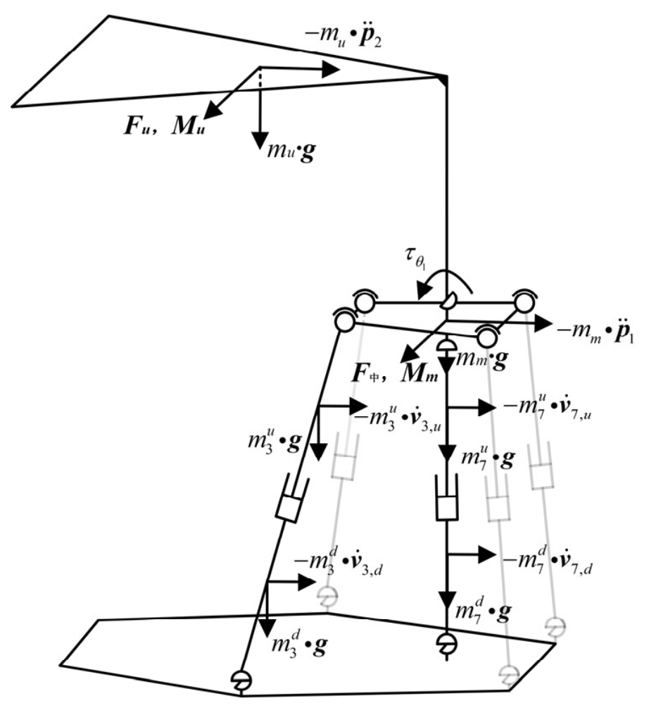
θ1 connecting the upper platform and the middle platform. The driving moment shown in
Figure 2 is denoted as
. According to Equation (5),
θ1 =
β2 −
β1 and
β1 = arctan(
x1/
z1), so
can be solved. The Jacobian matrix
is derived by differentiating the inverse kinematic equations. Thus, its virtual work is written as
In summary, the virtual work of all components in the non-redundant system is summed up. According to the virtual work principle, the total virtual work equals zero. After rearrangement, we obtain
where
is the generalized mass matrix, which is derived from the total kinetic energy of the upper platform, middle platform and all connecting branches;
denotes the coefficient matrix of Coriolis and centrifugal forces;
is the generalized gravity term;
represents the Jacobian matrix under the non-redundant condition, whose row vectors are
and
; and
is the vector of driving forces and moments. When the mobile robot is at a non-singular configuration,
is invertible, and the unique solution of the driving forces is obtained as:
3.2. Dynamic Modeling of Redundantly Actuated Robots
Under the redundantly actuated condition, the mobile robot is equipped with two additional active RPR branches on the basis of the original five non-redundant actuators. Combining all active actuators, the driving vector of the robot in the redundant actuation mode can be written as:
The upper platform still has five degrees of freedom in this mode, so the degree of redundancy of the robot is two.
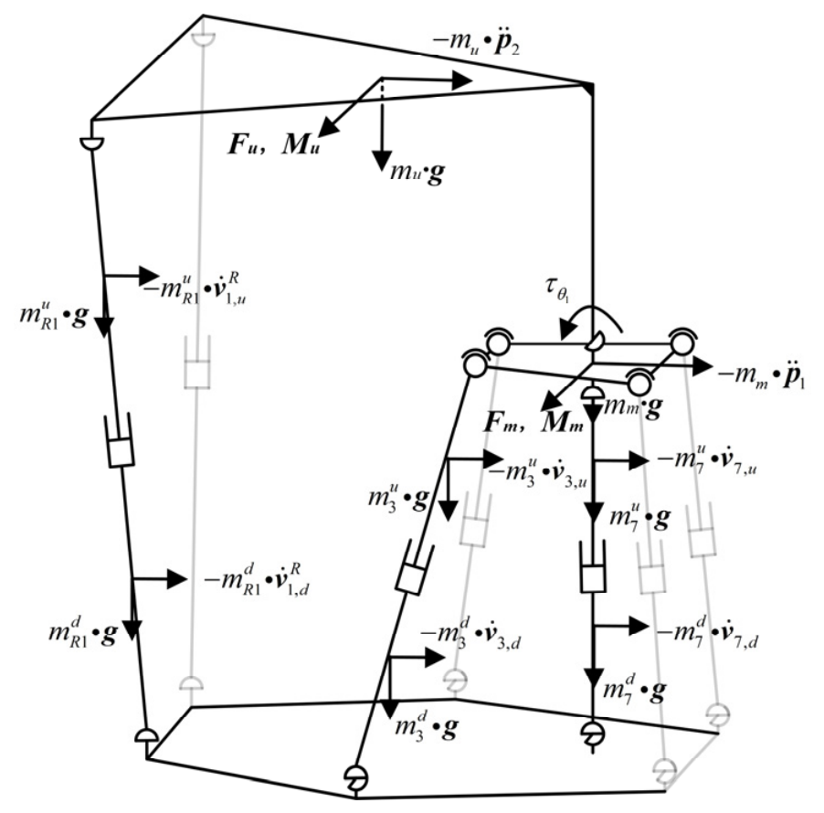
As shown in
Figure 3, according to the structural characteristics of the mobile robot, the two RPR branches are connected to the upper platform and the Lower Platform I respectively. The driving lengths of the two branches are defined as
lj(
j = 1, 2). Each RPR branch is divided into an upper link and a lower link. Let the mass of the upper link be
and the mass of the lower link be
, with the corresponding inertia tensors denoted as
and
.The two endpoints of each branch are defined as
Aj and
Cj(
j = 1, 2). The upper endpoints
Aj are connected to the upper platform via revolute joints, while the lower endpoints
Cj are mounted on the front bracket of the fixed Lower Platform I. Since the lower platform is stationary, the coordinates of
Cj remain constant and their velocities are zero. The velocity of
Aj attached to the upper platform is
, and
is the corresponding Jacobian matrix. Similar to the UPS branches in the non-redundant actuation system, the upper link and lower link share the same angular velocity, which is expressed as
The centroid velocities of the upper and lower links are denoted as
and
, respectively. Both can be expressed as a linear combination of the driving velocity
and the velocity
of the upper endpoint, and can also be written as linear functions of
.
Similarly, the total virtual work of each redundantly actuated RPR branch can be derived as
For the virtual work of other components excluding the two RPR branches, the expressions for four UPS driving branches, the upper platform, the middle platform, the UPR branch and the revolute joint
θ1 remain consistent with those under the non-redundant constraint mode. Only the driving force terms
and
among the five driving terms are retained. In summary, the virtual work of all components of the mobile robot is summed up. Based on the virtual work principle, the equation can be rearranged as follows:
As the number of variables changes, the corresponding Jacobian matrix varies. Accordingly,
and the driving force vector
can be extended to
The above formula consists of five equations with seven unknowns, forming an underdetermined system of equations. After prescribing the desired trajectory of the upper platform, the right-hand term is denoted as , which is a definite and unique five-dimensional vector. Nevertheless, the force vector satisfying , has infinitely many solutions. Consequently, the distribution of driving forces for the redundantly actuated system yields multiple solutions and a unique solution cannot be obtained. Additional constraints are therefore required, which can be formulated according to specific optimization objectives.
Various methods are currently available for solving the driving force distribution of redundantly actuated parallel mechanisms, typically including the least squares method, energy optimization method, generalized inverse method, boundary constraint method, weighted generalized inverse method, and rigid–flexible hybrid method. Since all driving branches of the mobile robot share an identical structure, the generalized inverse method is adopted to simplify the calculation. According to the generalized inverse matrix theory, the minimum-norm solution of the underdetermined constraint equations corresponds to the minimum energy solution of the parallel mechanism, which can be solved by means of the pseudoinverse. The generalized inverse solution is expressed as:
Thus, the minimum-norm solution of driving forces for the redundantly actuated system is expressed as:
It should be noted that the pure Moore–Penrose pseudoinverse matrix yields a mathematically minimum-norm solution, which may generate non-physical forces exceeding the output upper limits of the end-effector. Therefore, in the practical design of the control strategy, the force of each actuator should be constrained within a certain range: fi,min ≤ fi ≤ fi,max. During simulation and prototype experiments, force-protection limits shall be enforced in the control loop whenever the computed force exceeds the upper bound of the end-effector.
3.3. Dynamic Simulation Verification of Redundantly Actuated Mobile Robot
Based on the dynamic analysis of the mobile robot under redundant and non-redundant actuation modes, the correctness of the derived dynamic model is verified via Adams. Firstly, the robot model is established in SolidWorks 2022 and then imported into Adams 2022. After assigning actual material properties and driving forces, dynamic simulation is carried out following the preset trajectory of the upper platform. Based on application scenarios, kinematic-performance analysis and dimensional optimization of the robot, the initial structural parameters of the mechanism are obtained as follows: a1 = 306 mm, b1 = 598 mm, k1 = 359 mm, a2 = 102 mm, b2 = 255 mm, k2 = 214 mm, l8 = 275 mm. Since mobile robots frequently encounter obstacles, they are required to perform human-like left–right swinging motions for obstacle avoidance. Accordingly, the upper platform of the mobile robot is designed as a moving component, whose trajectory is defined as periodic swinging along the Y-axis while maintaining a horizontal attitude throughout the whole motion. One complete swinging cycle lasts 16 s, and the lower platform remains stationary during operation. To keep the upper-layer platform horizontal at all times, the middle platform is also constrained to a horizontal state. According to the kinematic singularity analysis, the robot has no singular configurations within this swinging cycle.
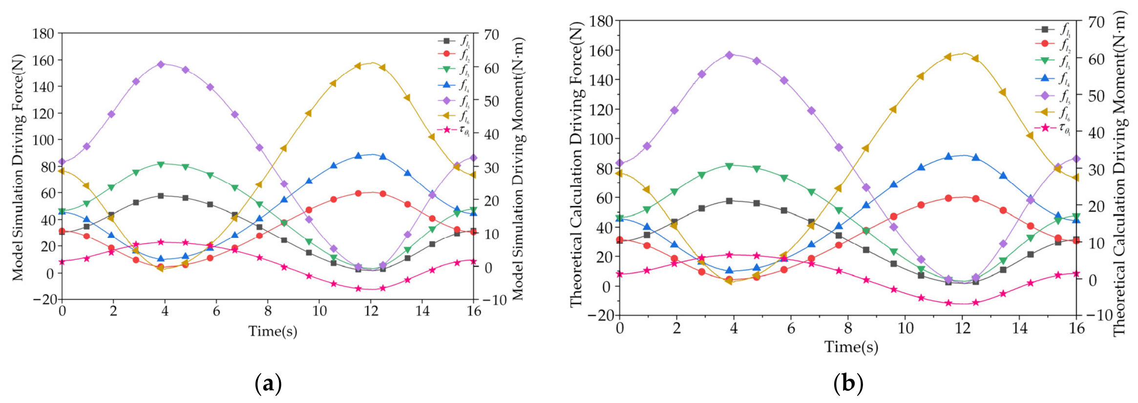
According to the preset swing trajectory of the upper platform, the variation curves of driving forces and moments for #1 to #5 actuators are obtained via inverse kinematics analysis and then imported into Adams. Based on the above dynamic analysis of the mechanism, the force curves of #6 to #7 actuators are calculated and imported to define the loads acting on the two RPR branches. During the simulation in Adams, the linear driving forces and rotational driving moments of #1 to #5 actuators throughout the motion are recorded. The simulation results are further compared with the values calculated by the dynamic model established in this chapter.
It can be seen from
Figure 4 that the distribution of driving forces and moments obtained by model simulation is basically consistent with the theoretical calculation results. This verifies that the established dynamic model can accurately reflect the force transmission and load distribution characteristics of the mechanism, and demonstrates the correctness of the model and the reliability of subsequent simulation analysis.