Article

A Heavy-Duty, High-Lift, Two-Module Swerve-Drive Mobile Robot for Off-Site Construction

1
Department of Electrical and Computer Engineering, College of Information and Communication Engineering, Sungkyunkwan University, Suwon 16419, Republic of Korea
2
Department of User Convenience Technology R&D, Korea Institute of Industrial Technology (KITECH), Ansan 15588, Republic of Korea
3
Department of Intelligent Robotics, College of Engineering, Sungkyunkwan University, Suwon 16419, Republic of Korea
4
Hitech & Overseas Team, JUNGDO Co., Ltd., Seoul 05574, Republic of Korea
*
Author to whom correspondence should be addressed.
Machines 2026, 14(8), 842; https://doi.org/10.3390/machines14080842
Submission received: 2 July 2026 / Revised: 18 July 2026 / Accepted: 23 July 2026 / Published: 25 July 2026
(This article belongs to the Section Robotics, Mechatronics and Intelligent Machines)

Abstract

This study addresses an off-site construction (OSC) task: installing heavy prefabricated equipment modules at elevated positions inside existing structures. The task simultaneously demands multi-ton payload capacity, a lift height approaching 10 m, and holonomic maneuvering in narrow aisles; to the authors’ knowledge, no single reported platform satisfies all three. We present a heavy-duty, high-lift mobile robot that lifts 6 t to 8 m. Two active swerve-drive modules and three passive casters form a five-point asymmetric layout combining holonomic mobility with load distribution, and the lift unit functionally decouples the vertical stroke (four helical band actuators) from the lateral stiffness (four scissor-stabilizing mechanisms). Planar motion is partitioned into three driving modes with closed-form forward and inverse kinematics, and zero-velocity transitions remove the kinematic model mismatch and the instantaneous-center-of-rotation discontinuity of a single unified model. Prototype measurements confirmed the motor-sizing torque assumptions, and chassis finite element analysis showed a factor of safety above 2.0 under maximum payload and quantified the in-plane stress induced by kinematic mismatch. In two field deployments, the robot reduced personnel by 25.0–27.3%, equipment by 42.9–60.0%, and installation duration by 50.0–85.7% relative to the incumbent methods, thereby extending mobile robots from horizontal transport to vertical OSC module installation.

1. Introduction

The construction industry is undergoing a structural shift from on-site construction to off-site construction (OSC), driven by chronic labor shortages, productivity stagnation, and tightening sustainability regulations [1,2]. Behind this shift lies a pronounced stagnation in productivity growth. Over the past two decades, labor productivity in construction has increased by only approximately 1% per year, which is far below the growth rates of other industries, such as manufacturing, over the same period [3]. Therefore, the shift to OSC is understood as an industrial response to this structural limitation. The effects of this shift have been quantitatively confirmed. Modular construction is reported to reduce on-site labor requirements by 20–40% and shorten construction schedules by 20–50% relative to conventional on-site methods [2]. Case studies that applied an integrated process management system on actual sites have consistently reported improvements in work efficiency and accuracy, along with reduced waiting times [4]. In market terms, the permanent modular construction market in the United States alone reached USD 20.3 billion in 2024, accounting for approximately 5.1% of all new construction activity [5].
As the OSC industry matures, two technical trends are accelerating in parallel. First, the unit weight of prefabricated equipment modules is increasing, and single modules exceeding several tons are becoming common. Second, the growing use of ceiling-mounted equipment modules, such as piping, ducts, and electrical trays, is increasing the installation height required to align and place them on the ceilings and upper parts of existing structures. The target of this study is not the volumetric building module that forms the building structure itself. Instead, it is the equipment OSC module, typified by the piping of production plants, installed at single-digit-meter heights in such locations. The combination of these two trends imposes unprecedented payload and lift-height requirements on on-site lifting equipment; these requirements form the starting point of the technical problem addressed in this study.
However, conventional on-site lifting equipment, namely chain blocks, self-propelled scissor lifts, forklifts, spider cranes, and strand jacks, was not designed for these OSC operating conditions, and each type addresses only part of the combined challenge of heavy payload, high lift height, and maneuverability. In particular, this equipment class carries a high risk from an industrial safety perspective. Cranes and forklifts are among the most hazardous equipment categories in U.S. industry [6,7]. Crane-related fatalities have been repeatedly reported in the construction industry [6,8,9], and forklifts have been identified as a major cause of serious and fatal injuries [10,11]. Falls from aerial lifts and the dynamic instability of scissor lifts have also been reported as separate hazards [12,13]. These risks intensify in multi-ton, high-lift operations. Moreover, because conventional methods require multiple machines and workers to handle heavy loads repeatedly for each module, they increase workers’ exposure to hazards.
Consequently, no single platform provides all three capabilities required for OSC module installation: a multi-ton payload, a single-digit-meter lift height of up to approximately 10 m, and holonomic mobility in narrow aisles (Table 1).
The pattern of unmet requirements in Table 1 forces OSC contractors to operate several machines in combination for each module, which amplifies setup time, labor input, and safety risk.
Autonomous mobile robots (AMRs) have already been widely applied to the transport of multi-ton payloads in confined spaces in the logistics and warehousing sectors [14,15]; however, such applications are inherently limited to horizontal material handling. That is, although multi-ton payload transport and holonomic mobility have been addressed within logistics AMRs, the vertical lifting of up to approximately 10 m, which is required for OSC module installation, remains largely unexplored in commercial systems. Moreover, satisfying both multi-ton load support and holonomic mobility with a single drive family is not straightforward. Differential drive, which dominates logistics AMRs, is unsuitable for holonomic mobility in narrow aisles because of its non-holonomic constraint, whereas omnidirectional and Mecanum wheels provide holonomic mobility but have inherent limitations in multi-ton load support and precise position control [16]. Therefore, a mobile robot suited to OSC lifting tasks must satisfy two design requirements simultaneously. Specifically, a vertical lifting mechanism capable of raising a multi-ton payload to a height of up to approximately 10 m must be integrated into the mobile chassis, and a drive family must be adopted that can bear multi-ton loads while enabling holonomic mobility and precise position control in narrow aisles.
In response to these requirements, this study proposes a heavy-duty, high-lift mobile robot that lifts a 6 t payload to a height of 8 m. This specification falls at the center of the region where no single equipment type in Table 1 satisfies the three-requirement combination on its own, namely, the band of multi-ton payloads and single-digit-meter (up to approximately 10 m) lift heights. The proposed platform lies at the intersection of two streams of prior research. First, vertical lifting mechanisms for mobile platforms have been studied in construction automation [17], cooperative transport [18], and scissor-lift-based automated guided vehicles (AGVs) [19]. However, they have typically been limited to light payloads of tens to hundreds of kilograms and lift heights of a meter or less, and have not addressed the OSC module lifting range. Second, the two-module swerve drive (2-SWD) family, which realizes holonomic mobility on conventional wheels using two active steering-and-drive modules, has been developed, since the inception of conventional-wheel holonomic mobility [20], into applications such as medical beds [21], among others [16]. However, to the best of the authors’ knowledge, no industrial deployment that simultaneously integrates multi-ton payload capacity and a vertical lifting mechanism has been reported in the peer-reviewed literature. Throughout this study, 2-SWD follows the definition of Tagliavini et al. [16].
The main contributions of this paper are summarized as follows:
  • Platform: A heavy-duty, high-lift mobile robot that lifts a 6 t payload to 8 m with holonomic maneuverability in narrow aisles is designed, prototyped, and industrially deployed. Its five-point asymmetric 2-SWD layout lowers the peak support-point reaction and frame stress relative to a four-corner layout, and its lift unit functionally decouples the vertical stroke from the lateral stiffness.
  • Three-mode driving strategy: Planar motion is partitioned into Ackermann, Diagonal, and Zero-Radius steering modes, with every mode change executed as a zero-velocity transition. The per-mode closed-form kinematics specialize the established 2-SWD relations [16,20] for implementation and odometry; the contribution is the operating strategy itself, which removes the instantaneous-center-of-rotation (ICR) discontinuity and kinematic mismatch of a single unified model and is justified for multi-ton operation above all by tip-over safety, together with the avoidance of the mismatch-induced stress quantified in Section 5.3 and the preservation of odometry integrity.
  • Structural and hardware verification: Motor sizing is validated against prototype measurements, and chassis finite element analysis (FEA) confirms a minimum factor of safety (FOS) of 2.59 under the maximum payload (criterion: FOS ≥ 2.0) while quantifying the in-plane stress induced by kinematic mismatch.
  • Industrial validation: Two construction-site deployments quantified reductions of 25.0–27.3% in personnel, 42.9–60.0% in equipment, and 50.0–85.7% in construction duration relative to the incumbent site methods.
Compared with the closest prior platforms, namely autonomous forklifts, scissor lifts and scissor-lift AGVs, logistics AMRs, and previously reported two-module swerve-drive systems for service and medical applications, the novelty of this work lies not in any single component but in integrating multi-ton payload capacity, multi-meter vertical lifting, and holonomic narrow-aisle maneuverability in one platform, and in validating this integration on active construction sites.
The remaining sections of this paper are organized according to the system hierarchy, from design to validation. Section 2 reviews the related work along three axes: industrial lifting equipment for OSC, holonomic wheeled mobile platforms and the 2-SWD, and vertical lifting mechanisms for mobile platforms. Section 3 presents the system architecture and design rationale of the platform, covering the system overview, the 2-SWD and three-caster wheel layout, and the integration of the helical band actuator and scissor mechanism. Section 4 presents the driving modes and kinematic models of the 2-SWD platform, including a diagnosis of the limitations of a single unified model, the three-mode driving strategy with zero-velocity transitions, and the forward and inverse kinematics for each mode. Section 5 addresses structural and hardware validation, covering motor torque analysis with prototype measurements and chassis FEA under maximum payload and kinematic mismatch conditions. Section 6 presents the experimental evaluation, comprising two field deployments and a discussion of the associated trade-offs. Section 7 concludes the paper with a summary of the main contributions, limitations, and directions for future work. The industrial validation in this study targeted piping OSC modules for production plant construction, and the operating domain was limited to a structured even floor.

2. Related Work

To situate the proposed platform within the landscape of prior work, this section reviews related work along a hierarchy of system abstraction, starting from industrial lifting equipment and proceeding to holonomic locomotion mechanisms and vertical lifting for mobile platforms. Because these fields have developed independently of one another, this review considers both the maturity of each field and the gap in integrating them under the single operational goal of OSC module installation.

2.1. Industrial Lifting Equipment for OSC

As presented in Section 1, the process, management, and market benefits of OSC have been reported repeatedly [1,2,3,4,5]; however, engineering studies of the lifting equipment responsible for the physical installation of OSC modules are relatively scarce. Therefore, this subsection reviews the representative industrial lifting equipment used for on-site module installation, namely chain blocks, self-propelled scissor lifts, forklifts, spider cranes, and strand jacks, in terms of operating principle, rated load and lift height, maneuverability, and safety, and summarizes the limitations of each for OSC module installation. The ranges of the rated load and lift height given below are representative values for typical industrial specifications and may vary with the model, manufacturer, and applicable standard.
The chain block is the most basic equipment type, and it lifts loads manually (or electrically) through a load chain and gear reduction. Suspended from a fixed overhead anchor, such as a beam or trolley, it provides purely vertical hoisting. Its rated load ranges from hundreds of kilograms to tens of tons (typically 0.25–20 t, up to approximately 50 t for large units); however, the lift height depends on the chain length, and horizontal movement relies on a separate runway and trolley. Because a fixed anchor is assumed, it has no ground mobility and cannot move or install a module at a site.
The self-propelled scissor lift is a mobile elevating work platform that raises its platform vertically by hydraulically deploying pantograph-type scissor links and has a drivable chassis. Its working height reaches approximately 6–18 m, but its rated load is typically 230–1000 kg, which presupposes the transport of workers and light materials, and its lateral and torsional stiffness and tip-over stability degrade sharply as the lift height increases. Tip-over under side loading, incline, or maximum extension conditions [13] and falls from aerial work platforms [12] have been reported as representative hazards, making such lifts unsuitable for multi-ton module lifting.
A forklift is an industrial vehicle that offsets a cantilever load with a rear counterweight and lifts and transports unit loads using forks mounted on a hydraulic telescopic mast. Its rated load is 1–10 t for standard types and approximately 45–50 t for large units, such as container handlers, and its lift height is typically 3–7 m (higher for high-lift and reach masts). Owing to the wide turning radius and non-holonomic behavior of the rear-wheel steering, together with the cantilever load and counterweight structure, the tip-over limitation becomes pronounced as the lift height increases. Forklifts have been identified as a major cause of serious and fatal occupational injuries [10,11]. They are effective for horizontal transport and medium-height lifting, and their non-holonomic steering reflects a deliberate design trade-off. For the multi-ton class, however, the residual capacity of a counterbalance forklift decreases sharply with lift height, and the required operating aisle grows with truck size. In addition, piping modules are typically several meters long. Carried on cantilever forks, such a module projects ahead of the truck and enlarges the swept path in every turn, so the aisle required for transport grows with module length as well. The trade-off therefore becomes unfavorable in the target domain, which combines narrow aisles between installed equipment, long modules, and installation heights of up to 8 m. More fundamentally, these equipment classes are general-purpose machines and were not designed for the piping-module installation method considered here. The method requires carrying the module within the vehicle footprint, lifting it to 8 m, and placing it precisely between installed equipment, all with a single platform. Commercial forklifts and scissor lifts each provide only part of this combination, and the research platforms reviewed in Section 2.4 do not cover it either. By contrast, the proposed platform carries the module within its own footprint and repositions it by lateral translation and in-place rotation. In this target domain, the trade-off therefore resolves in favor of a holonomic drive.
The spider crane is a compact crawler-type mini-crane with independently deployable outrigger legs (a spider-like stance) and a telescopic boom, designed to pass through standard doorways and enter indoor and confined spaces. Its hydraulic lifting system and mechanical structure have been analyzed [22], and it has been regarded as an economical lifting alternative for confined spaces that large cranes cannot enter. Its rated load, approximately 1–10 t, is significantly lower than that of large cranes and also depends on the radius; hoisting requires outrigger deployment (a setup footprint) and the presence of an operator, whether on-site or remote. It resolves the problem of confined spaces inaccessible to large cranes; however, its low capacity, outrigger footprint, and operator dependence prevent it from combining holonomic mobility with hoisting.
The strand jack raises and lowers ultra-heavy loads using a hollow-plunger hydraulic jack that grips a bundle of high-tensile steel strands with anchor wedges and pulls them up in steps. It is used to lift an entire ultra-large structure, assembled on the ground, to a target height, and multiple jacks are synchronized for large structures. Its rated load ranges from tens to thousands of tons; however, it is stationary and requires a reaction-support structure (a tower or gantry) and extensive rigging, and most strand jacks operate discontinuously and slowly because of the repeated start-stop of piston extension and retraction. To mitigate this discontinuity, consecutive lifting-and-lowering electrohydraulic strand-jack systems have been studied [23]. Its one-off ultra-heavy lifting capability is unmatched by other equipment; however, it has no ground mobility and is therefore unsuitable for repetitive on-site module installation.
In summary, these machines satisfy only part of the combined requirement of heavy payload, high lift height, and holonomic mobility: the chain block (vertical hoisting, fixed, manual), the scissor lift (high lift, payloads below 1 t), the forklift (transport, medium lift, non-holonomic, tip-over-prone), the spider crane (confined access, low capacity, outriggers), and the strand jack (ultra-heavy, stationary, rigging). Furthermore, these machines carry a high risk of accidents in multi-ton, high-lift operations, which adds a safety burden on top of the functional limitations mentioned above.
Research gap: None of the equipment reviewed in this section satisfies, on its own and within acceptable safety, the three capabilities that OSC module installation simultaneously requires: heavy payload, high lift height, and precise holonomic mobility.

2.2. Holonomic Wheeled Mobile Platforms and the Two-Module Swerve Drive

Precise positioning in narrow aisles requires holonomic mobility, in which a vehicle can translate in any direction and rotate in place. The mechanical configurations of wheeled mobile robots and their modes of holonomic mobility have been surveyed in several review studies [14,15,16], which show that the choice of drive type is a trade-off among payload support capacity, positioning accuracy, and floor adaptability. This subsection reviews holonomic wheeled locomotion in three categories.
First, the special wheel family (omnidirectional and Mecanum wheels) realizes holonomic mobility through a simple mechanism that uses passive rollers; however, the discontinuity of roller-to-floor contact imposes inherent limitations on multi-ton load support, robustness to floor debris, and precise positioning and introduces vibration [15,16]. Second, the independent steering-and-drive family steers and drives conventional wheels independently to secure heavy-load support and traction. The kinematics, dynamics, control, and trajectory tracking of four-wheel independent steering/four-wheel independent drive (4WIS/4WID) vehicles have been actively studied [24,25,26]; however, because the ICRs of all wheels must be matched, steering angle singularities and discontinuities arise for certain ICR geometries. Third, the active caster family places an offset between the steering axis and the wheel contact point to circumvent the non-holonomic constraint of conventional wheels. Wada and Mori [20] first demonstrated a conventional-wheel holonomic vehicle. Chung et al. [27] proposed a dual offset active caster wheel with orthogonal velocity components, realizing holonomic omnidirectional mobility with conventional wheels; their prototype experiments demonstrated reliability and durability independent of floor conditions, as well as precise positioning.
The 2-SWD, which realizes holonomic mobility with two active steering-and-drive modules, lies at the intersection of the second and third families. Throughout this paper, 2-SWD follows the definition of Tagliavini et al. [16], that is, a wheeled mobile platform with two independently steered and driven conventional-wheel modules complemented by passive casters. Since the inception of conventional-wheel holonomic mobility [20], this configuration with two steering-and-drive modules has been instantiated in domestic service robots [28] and holonomic medical beds [21], among others, and has also been addressed in the context of Industry 4.0 mobile manipulators [29] and the systems-engineering-based design of an omnidirectional AGV [30]. In addition, the suspension design of the service robot Paquitop [28] suggests that maintaining ground contact while distributing the load in an asymmetric multipoint contact configuration is a distinct design challenge. Control of disturbed nonlinear systems concerns the tracking layer and is complementary to the present work, whose scope is the mechanism design, the kinematic formulation, and the structural and industrial validation of the platform. The prototype employs industrial servo control under the CiA 402 drive profile over EtherCAT, which proved sufficient for the quasi-static operating profile of the target installation tasks.
In summary, the 2-SWD is a drive family suited to the operating conditions of this study, which simultaneously require multi-ton payload support, precise positioning, and holonomic mobility in narrow aisles.
Research gap: Prior 2-SWD cases have been limited to lightweight service and medical applications, and neither the asymmetric wheel arrangement for multi-ton load distribution nor the ICR discontinuity problem of a single unified kinematic model has been addressed in depth.

2.3. Vertical Lifting Mechanisms for Mobile Platforms

This subsection examines the mechanism topology for integrating a lifting function into a mobile robot platform. Mechanisms that integrate vertical lifting into a mobile platform are broadly classified into scissor mechanisms, linear actuators, and multi-robot cooperative lifting mechanisms. Scissor mechanisms, which are widely adopted for their compact stowage and large lift ratio, have been reported in the parametric dimensional design of double-stage scissor lifts [31] and in an automatic pick-and-place AGV based on a scissor lifting platform [19]. However, the lateral stiffness and stability of a scissor mechanism degrade sharply as the lift height increases, and Dong et al. [13] experimentally established that the dynamic instability of a scissor lift depends on the tilt angle and tilt rate.
On the linear-actuator side, the analysis and design of long-stroke linear actuators have been reported [32], and research on multi-robot cooperative transport and co-manipulation has presented an approach that circumvents the lifting limit of a single platform through load distribution [18]. However, the reported cases range from sub-kilogram laboratory prototypes [18] to payloads of at most a few hundred kilograms, with lift heights of a meter or less, and they do not address the multi-ton, single-digit-meter range required for OSC module lifting.
Meanwhile, the autonomous forklift is the most direct case of combining mast-and-fork vertical lifting with autonomous mobile navigation. Walter et al. [33] showed that a multi-ton autonomous forklift can perform the entire process of perceiving and approaching pallet loads in an outdoor environment, lifting them, and transporting and stacking them. These platforms inherit the cantilever forks, rear counterweight, and non-holonomic steering of commercial forklifts, and with them the trade-off described in Section 2.1: the residual capacity at height, the required operating aisle, and the swept path of long modules become unfavorable at the operating point of this study. Telescopic masts and rigid (push) chain column-type actuators are also used as lifting means; however, no peer-reviewed study identified in this review has analyzed or designed a lifting mechanism that combines a multi-ton, several-meter lift with a mobile platform. In particular, band-type and chain-type column actuators provide compact stowage but have low stiffness in the direction perpendicular to the lift axis; therefore, they require a separate lateral stabilizing mechanism at high lift heights.
Research gap: Prior studies have not addressed a mobile-platform-integrated lifting mechanism that raises a multi-ton payload to approximately 10 m while simultaneously securing the lateral stiffness and stability required at high lift heights.

2.4. Summary and Motivation

The three axes reviewed in this section are areas in which considerable research has accumulated. Industrial lifting equipment effectively provides, by type, part of the combination of heavy payload, high lift height, and maneuverability; holonomic wheeled mobile platforms and the 2-SWD form a drive family that realizes omnidirectional mobility in narrow aisles with conventional wheels; and vertical lifting mechanisms for mobile platforms likewise rest on established approaches—scissor mechanisms, linear actuators, and multi-robot cooperation. However, these areas have developed independently of one another, and none of the work reviewed above has integrated them under the single operational goal of OSC module installation.
Therefore, the gap addressed in this study lies not in the absence of individual areas but in the absence of an integration that connects them. This integration is not straightforward because the requirements imposed by OSC module installation are mutually coupled and in conflict. The single-digit-meter lifting of a multi-ton payload raises the system center of gravity (CoG), which directly ties the expansion of the lifting capability to the difficulty of securing stability at high lift heights. Multi-ton load support and holonomic mobility in narrow aisles conflict in the choice of drive family. Accommodating a single-digit-meter lift stroke within a limited vehicle height conflicts with securing lateral stiffness at high lift heights. In summary, a platform for OSC module installation must resolve these conflicts simultaneously within a single integrated design rather than individually.
Table 2 summarizes the closest prior platforms against the three requirements identified above, together with their validation environments. Each platform class satisfies at most part of this combination, and none has been validated on an active construction site.
This study resolves these conflicts with a single integrated platform and develops its design, three-mode driving strategy, structural validation, and industrial validation in the following sections.

3. System Architecture and Design Rationale

This section translates the three requirements identified in Section 2, namely a multi-ton payload, a single-digit-meter lift height, and holonomic maneuvering in narrow aisles, into the concrete architecture of the proposed platform. The basic design policy is to integrate horizontal mobility and vertical lifting into a single chassis while separating each function into a dedicated subsystem (functional decoupling) and to right-size the drive system to the operating domain of a structured, even floor. For each design decision, this section states the requirement it responds to and the rationale behind it at the 6 t/8 m operating point; the quantitative verification of these decisions follows in Section 5 and Section 6. Table 3 summarizes this requirement–design–verification mapping, and Table 4 lists the main specifications of the prototype.

3.1. System Overview

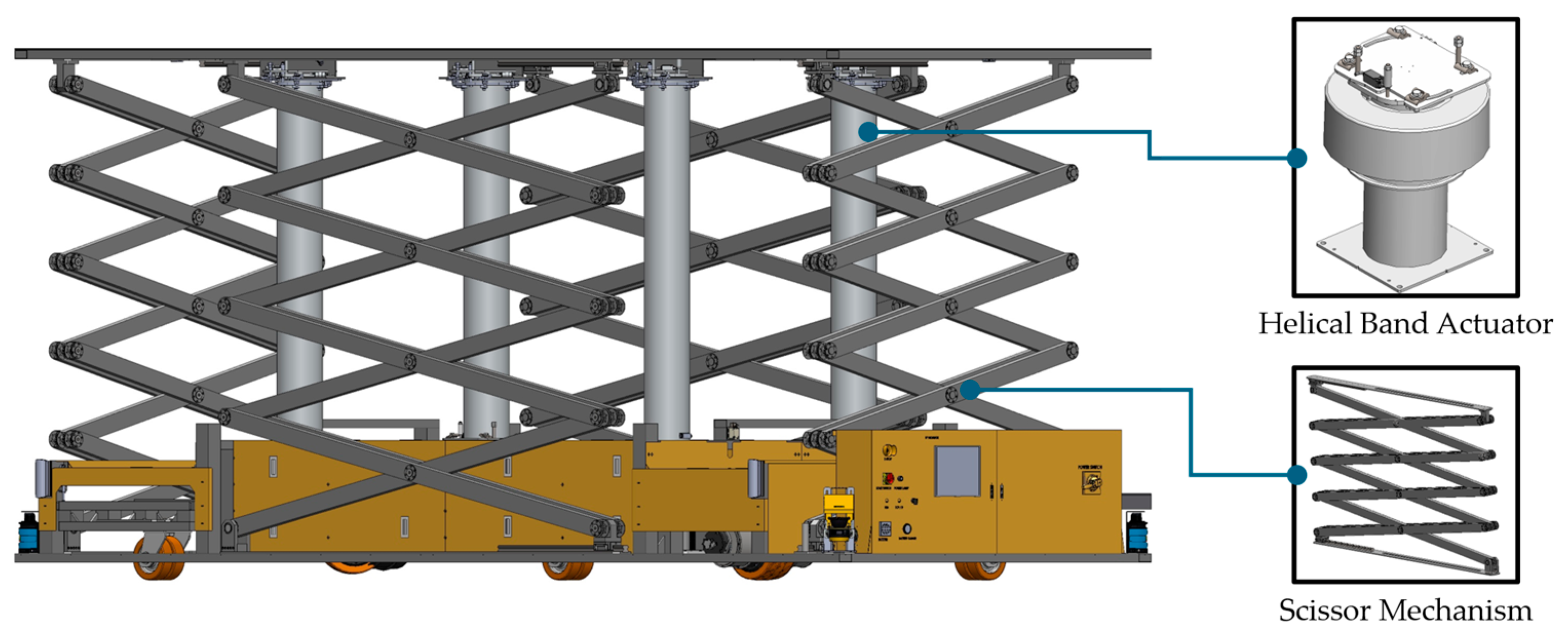
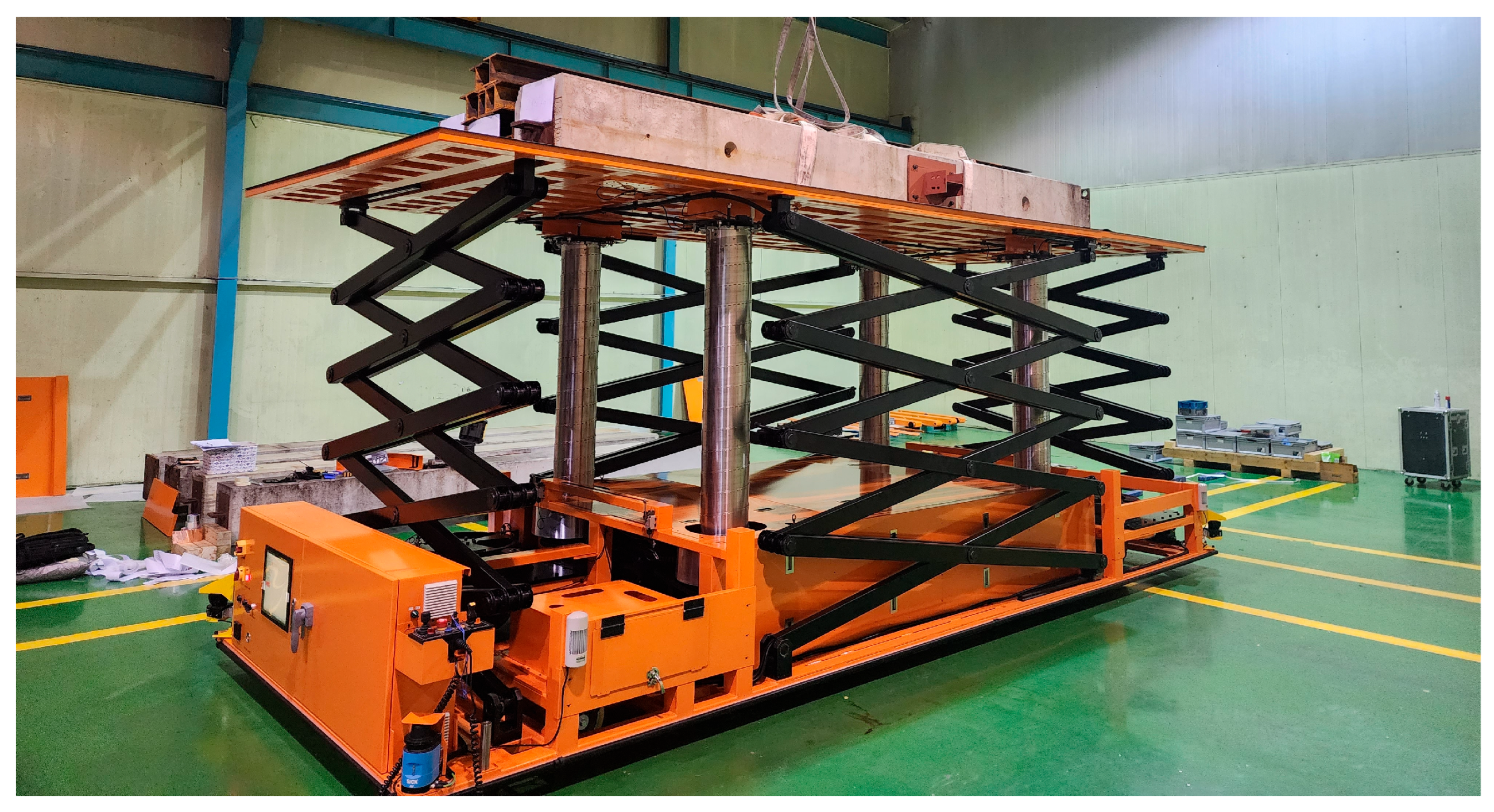
This subsection presents the overall configuration of the proposed integrated platform. Figure 1 shows the prototype of the platform, designed and built for the 6 t/8 m operating point; a vertical lift unit consisting of four helical band actuators and four scissor-stabilizing mechanisms is integrated on top of a 2-SWD mobile base that provides horizontal mobility. The platform is built to operate on the structured, even floor of OSC factories and sites.
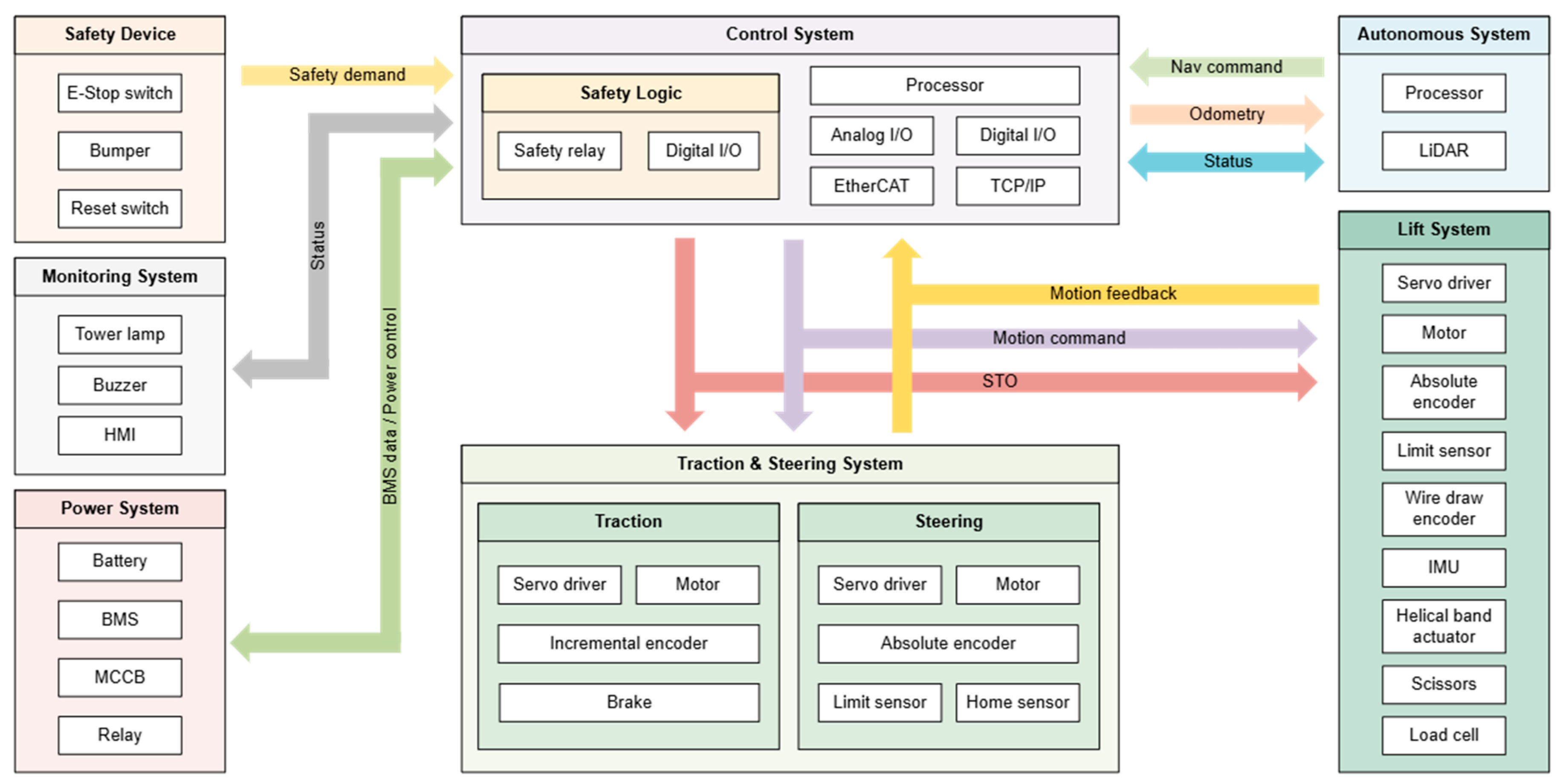
Figure 2 shows the system architecture of the platform, presenting the subsystem decomposition in which the functional decoupling policy of the introduction is implemented at the system level. The platform consists of seven subsystems: a control system, a traction and steering system, a lift system, an autonomous system, a power system, a safety device, and a monitoring system. Among these, the traction-and-steering, lift, and autonomous subsystems are functional subsystems that directly perform the platform’s active mobility, lifting, and perception functions, whereas the control, power, safety, and monitoring subsystems are supporting subsystems that mediate and support the operation of the functional subsystems.
The functional subsystems divide their roles as follows. The traction and steering system implements the two active 2-SWD modules, each combining a traction part and a steering part, and is responsible for the holonomic mobility in narrow aisles. The lift system performs vertical lifting of up to 8 m using four helical band actuators and four scissor-stabilizing mechanisms, with redundant lift-height sensing and with attitude and payload measurement. The autonomous system, consisting of a LiDAR and a dedicated processor, handles environmental perception and localization and exchanges navigation commands, odometry, and status information with the control system; worker-independent autonomous operation builds on this subsystem, but its integration and demonstration are beyond the scope of this study. The sensor and actuator composition of each subsystem, together with the main specifications of the prototype, is summarized in Table 4.
The supporting subsystems mediate the operation of the functional subsystems and manage the safety, power, and operational states of the platform. The control system has, at its core, a dual structure of a safety logic domain and a main processor domain. The safety logic domain processes safety demands from the safety device through a safety relay and digital I/O, whereas the main processor domain governs the entire platform through analog and digital I/O as well as EtherCAT and TCP/IP communication. Through the EtherCAT real-time motion bus, as a safety function, it sends a safe torque-off (STO) signal directly to the servo drivers of these systems. The power system consists of a battery, battery management system (BMS), molded-case circuit breaker (MCCB), and relays, and exchanges BMS data and power control signals with the control system. The safety device consists of an emergency-stop switch (E-stop), bumpers, and a reset switch and conveys safety demands to the safety logic. The monitoring system displays the operational state using a tower lamp, a buzzer, and a human–machine interface (HMI).
In summary, the platform decomposes into three functional subsystems for horizontal mobility, vertical lifting, and autonomous driving, along with four supporting subsystems. This decomposition distributes the satisfaction of the three-requirement combination across the functional subsystems and chassis structure, allowing the design and validation of each requirement to be performed independently.

3.2. 2-SWD and 3-Caster Layout Design

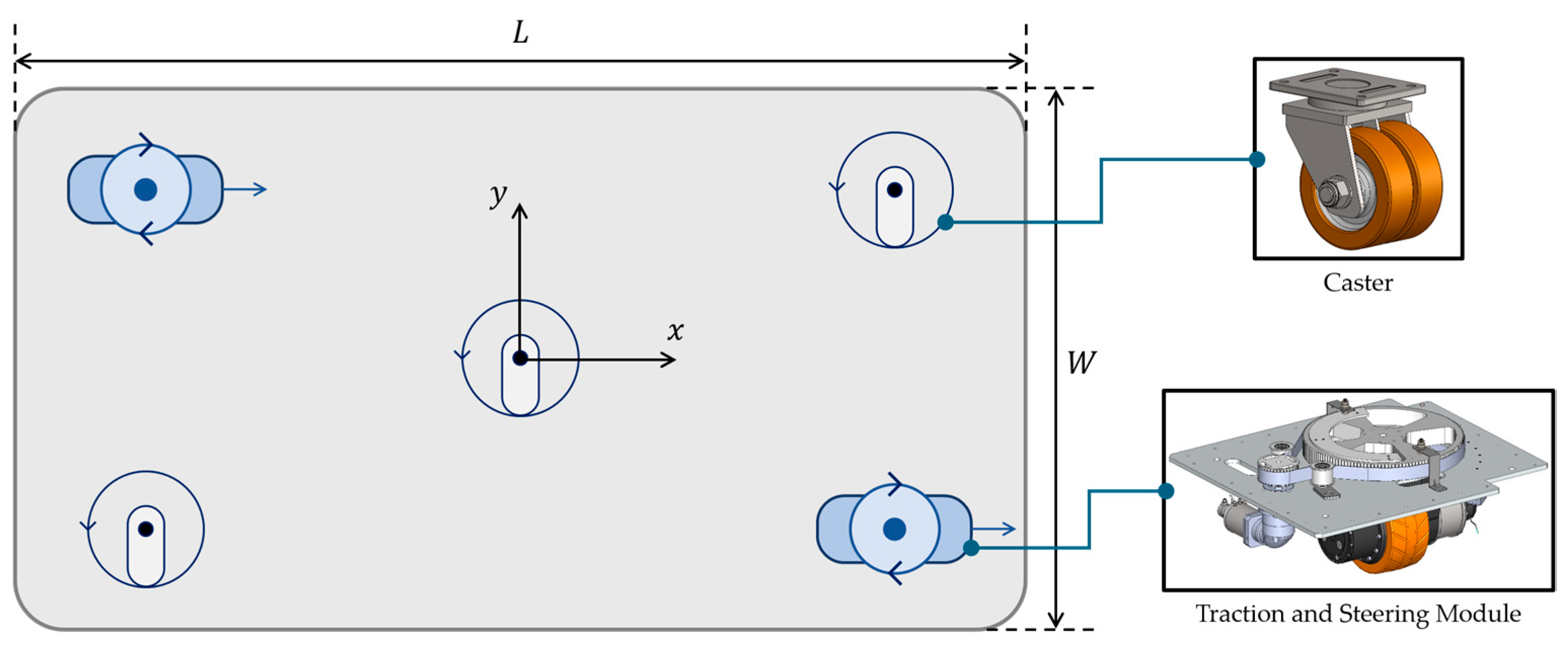
This subsection defines the geometry of the five-point asymmetric wheel layout that simultaneously provides support for a 6 t payload and holonomic mobility in narrow aisles and presents its design rationale. The wheel arrangement of the platform places five ground contact points on a rectangular planar chassis and is characterized by an asymmetric placement of two active modules and three passive casters about the diagonals. As shown in Figure 3, two active 2-SWD modules are placed at the two ends of one diagonal of the chassis plane, two corner casters at the two ends of the other diagonal, and one center caster at the chassis center, where the two diagonals intersect. Among these, the rear-right (RR) corner caster and the rear-left (RL) active module are mechanically coupled through a bogie and share a single load-transfer interface with the chassis. The planar coordinate frame takes the geometric center of the chassis as the origin and defines the reference driving direction as the x-axis, the vehicle left direction as the y-axis, and the vertically upward direction as the z-axis.
This asymmetric arrangement is a direct consequence of the right-sizing principle stated above. Because the 2-SWD achieves planar three-degree-of-freedom (3-DoF) holonomic mobility with only two active steering-and-drive modules, the platform secures the same motion freedom with two active modules and three passive casters instead of making all four corners active. The first design rationale is kinematic: the decision to place the two active modules at the two ends of a diagonal, rather than adjacent to each other, is based on two grounds. The first is the central alignment of the kinematic reference point. Because the origin of the body-fixed coordinate frame of the 2-SWD lies at the midpoint of the segment joining the two contact points [16], placing the two modules symmetrically at the two ends of a diagonal makes this midpoint coincide with the geometric center of the chassis, thereby aligning the reference for body motion with the center of the payload. The second is the rotational motion efficiency. The greater the distance between the two modules, the smaller the driving force required to generate the same turning moment in rotational motion, such as in an in-place rotation, and the diagonal arrangement maximizes the distance between the two contact points on a rectangular chassis. Both grounds are elementary geometric consequences of the layout; they are recorded here as design rationale. For these two reasons, the diagonal arrangement provides favorable geometric conditions for the three driving modes of the platform.
The second design rationale for the five-point asymmetric arrangement lies in the load distribution of the 6 t payload and chassis self-weight. In a four-corner symmetric layout, which places support points only at the four corners, the entire vertical load is concentrated at the four outer points, and because the chassis center is unsupported, the bending span between the support points becomes long. In contrast, the present layout adds a load path, the center caster, on the inner part of the chassis near the center of the payload; this shares the vertical reaction borne by the four outer points, lowering the peak support reaction, and simultaneously shortens the bending span, reducing the maximum frame bending moment. However, the five support points form a statically indeterminate structure with more unknowns than the three equations provided by planar static equilibrium; therefore, the reaction distribution among the support interfaces depends on the chassis structural stiffness and is analyzed numerically. In the chassis FEA of Section 5.2, the structural contribution of this center support is isolated by an ablation in which the center caster is removed; the five-point support lowers the maximum equivalent stress and the resultant displacement and raises the minimum FOS, and the four-point ablation additionally bounds the case of an unloaded center caster.
In summary, the five-point asymmetric wheel layout achieves holonomic mobility in narrow aisles through the diagonal arrangement of the two active 2-SWD modules and stable support of the 6 t payload through the distributed support of five points, including the center caster. It is configured such that the support polygon formed by the five contact points encloses the center of the payload, thereby ensuring static stability.

3.3. Integration of Helical Band Actuator and Scissor Mechanism

This subsection defines the structure of the vertical lift unit integrated within the wheelbase and presents the rationale for combining the lifting and stabilization functions into a single structure while maintaining their functional separation. As shown in Figure 4, the lift unit of the platform combines four helical band actuators with four scissor-stabilizing mechanisms and supports a 6 t payload at lift heights of up to 8 m. The design intent of this configuration is to implement the functional decoupling principle of the introduction at the level of the lift unit. Specifically, the helical band actuators are solely responsible for generating the vertical lift stroke, and the scissor-stabilizing mechanisms are solely responsible for meeting the lateral stiffness and stability requirements, which increase as the lift height increases. This avoids the over-specification or insufficient stability that arises when a single mechanism is responsible for both the lift force and the stability. The contribution of this subsection is the system-level design: the selection rationale at the 6 t/8 m operating point (the absence of hydraulic drift and a compact stowed volume), the integration that expands an approximately 1 m stowed unit to an 8 m lift height within a mobile chassis, and the assignment of the lifting stroke and the lateral stiffness to separate load paths, which is validated operationally in Section 6.
The helical band actuator responsible for the lift stroke is a long-stroke linear actuator in which band elements stowed in a coiled state interlock with each other under a rotational drive to form a rigid telescopic column. When lowered, the bands separate and are restowed compactly in a small winding unit at the base [32]. The platform adopts a helical band actuator rather than a hydraulic cylinder as its single-digit-meter lifting element for two reasons. First, because it is a rigid mechanical structure, platform drift arising from the pressure drop of a hydraulic system over time does not occur, which secures the precision and repeatability of height holding after lifting. Second, because its stowed volume is small, the piston storage space required by a hydraulic cylinder of the same stroke is unnecessary; therefore, a single-digit-meter lift stroke can be accommodated within the limited vehicle height of a mobile platform. The platform uses four commercial helical band actuators as lifting elements. These actuators provide a stroke of approximately 7.3 m, and the floor-referenced height of the platform deck varies from approximately 1 m in the stowed configuration to approximately 8 m in the deployed configuration. This high extension ratio directly demonstrates the compact folding characteristic of the helical band actuator.
The four scissor-stabilizing mechanisms reinforce the stiffness of the lift unit to secure lateral stability at high lift heights. According to Dong et al. [13], who analyzed the dynamic stability of scissor lifts through modeling and experiments, the stability of a scissor structure is weakest in the lateral direction, where the wheel span is shortest, degrades as the lift height increases, and improves when the stiffness of the scissor structure is increased. Because securing the lateral stiffness of the slender lift column becomes the dominant design challenge at a high lift height of up to 8 m, the four scissor-stabilizing mechanisms impart lateral stiffness to the lift unit and reinforce the lateral stability of the column.
In summary, through this functional decoupling, the lift unit meets the lift-force and high-lift-stability requirements of the 6 t/8 m operating point in a single integrated structure. It thereby addresses the lifting requirement identified in Section 2 and, through integration within the wheelbase, combines with the distributed support provided by the five-point asymmetric wheel layout described in Section 3.2.

4. Driving Modes and Kinematic Models of the 2-SWD Platform

Building on this wheeled drive base, this section presents the three-mode driving strategy of the platform and the kinematic models that support it, describing the correspondence between the steering and drive commands of the two active modules and the planar motion of the robot body. The kinematic foundation of the 2-SWD is sufficiently mature, as established in the prior work reviewed in Section 2 [16,20]; however, describing the entire motion range of the platform with a single unified kinematic model entails two essential limitations: kinematic model mismatch and ICR discontinuity. To avoid these limitations, this section partitions the planar motion of the platform into three driving modes, the Ackermann Steering Mode (curved driving), the Diagonal Steering Mode (crab driving), and the Zero-Radius Steering Mode (in-place rotation), and describes each mode with a dedicated kinematic model specialized from these established relations. Through this partitioning and the zero-velocity mode transition, the two limitations of a single model are resolved at the mode level.

4.1. Limitations of the 2-SWD Kinematic Model

The correspondence between the planar motion of the 2-SWD platform and the steering and drive commands of the two active modules was kinematically formulated in a previous study [16]. However, a single unified kinematic model of this correspondence across the entire motion range is structurally over-determined. In rigid-body kinematics, each active module contributes two contact-point velocity components; the two modules therefore impose four components that must be consistent with a single planar 3-DoF body twist (4 > 3). When a single model cannot guarantee this consistency over the entire motion range, the commands of the two modules generally fail to correspond to any rigid-body motion. Prior 2-SWD work likewise noted that such direct inverse-kinematic control is over-determined as a non-square mapping and difficult to stabilize by conventional methods, and circumvented this by reducing the number of control coordinates [20]. This subsection diagnoses the two essential limitations that follow: kinematic model mismatch due to over-determination, and ICR discontinuity at mode boundaries.
Kinematic model mismatch is how over-determination manifests as a physical inconsistency during operation, and it is most pronounced during transitions between driving modes, each of which requires realigning the modules to the steering angle of the new mode. If this realignment occurs while the drive wheels are rolling, the instantaneous combination of steering angles corresponds to no rigid-body motion. Because the nearly rigid body frame cannot absorb the incompatible module velocities through deformation, the inconsistency is transmitted as internal reaction forces and causes stress concentration; at the same time, drive wheels that violate the no-slip condition slip on the floor and accumulate odometry errors. Of these two effects, the internal body stress becomes a cause of chassis fatigue failure as transitions are repeated, and Section 5.3 quantifies its magnitude using FEA. The zero-velocity mode transition described in Section 4.2 removes the cause of this repeated stress, thereby minimizing the risk of chassis fatigue failure.
ICR discontinuity arises from the parameterization that consolidates the steering of the two modules into a single ICR in parts of the motion range. Because the planar motion of the body can be instantaneously regarded as pure rotation about the ICR, the velocity of an arbitrary point on the body is given by Equation (1), and the position of the ICR, with the body center as the origin, is given by Equation (2).
v C = ω z ^ × p C p I C R x ˙ = ω y C y I C R , y ˙ = ω x C x I C R
x I C R = y ˙ ω , y I C R = x ˙ ω
Equation (2) shows that the ICR is set by the body twist but also exposes the limits of this representation. In the Zero-Radius Steering Mode ( x ˙ = y ˙ = 0 ), the ICR lies at the body center; in the Ackermann Steering Mode y ˙ = 0 , it lies on the lateral axis at y I C R = x ˙ ω and diverges to infinity as the curvature decreases; and in the purely translational Diagonal Steering Mode ω = 0 , Equation (2) is undefined and no finite ICR exists. A continuous model that treats the ICR as a single parameter therefore has discontinuities and singularities at the mode boundaries, where the ICR appears, vanishes, or jumps, and it requires steering commands that are undefined or divergent there. Prior work similarly observed that a non-holonomic steered vehicle must stop and realign its wheels on trajectories with curvature discontinuities [20]. These singularities are not confined to the boundaries. As ω 0 , the ICR recedes without bound, so a small command change produces a large ICR displacement; and where one module’s contact-point velocity is instantaneously zero (the module lies on the ICR, or the body is at rest), its steering direction is undefined, and the inverse-kinematic computation becomes unstable, amplifying minute inputs into large steering angle changes.
In summary, both limitations arise from applying a single unified model uniformly over the entire motion range; therefore, they are essential constraints that cannot be removed by refining the model alone.

4.2. Three-Mode Driving Strategy

In this study, planar motion is partitioned into three driving modes, and each mode is described using a dedicated kinematic model. The three modes are not control algorithms in themselves. Rather, they constitute the set of motion modes selected and invoked by two planning layers [15]: global path planning, which generates a path from the start to the goal on an environment map, and local path planning and trajectory tracking, which convert that path into commands executable under the robot’s kinematic constraints. This subsection situates the three modes on these two layers and presents the role of each mode and the strategy for transitioning between modes.
At the global layer, the holonomic nature of the 2-SWD platform broadens the freedom of path generation. Whereas a car-like non-holonomic platform requires a complex sequence of maneuvers for lateral motion [20], the 2-SWD is capable of translation in any direction and independent rotation; thus, global path planning can directly generate paths that include lateral and oblique segments and in-place changes in direction without a curvature-continuity constraint. Each segment of the generated path is assigned in advance, at the planning stage, to one of the two macro-transport modes according to its geometry. The Ackermann Steering Mode follows a circular arc centered on the ICR and realizes curves of various radii according to the commanded velocity and curvature. Accordingly, when a curved segment of the global path is realizable in this mode, the segment is assigned to the Ackermann Steering Mode. The Diagonal Steering Mode performs parallel translation without rotation, and a segment that can be traversed from the current position to the next by straight or oblique translation is assigned to this mode. Prior comparative results, which show that the 2-SWD is kinematically advantageous in pure translation and roto-translation, support the macro-transport role of these two modes [16]. A systematic method for this segment-wise mode assignment is left for future work.
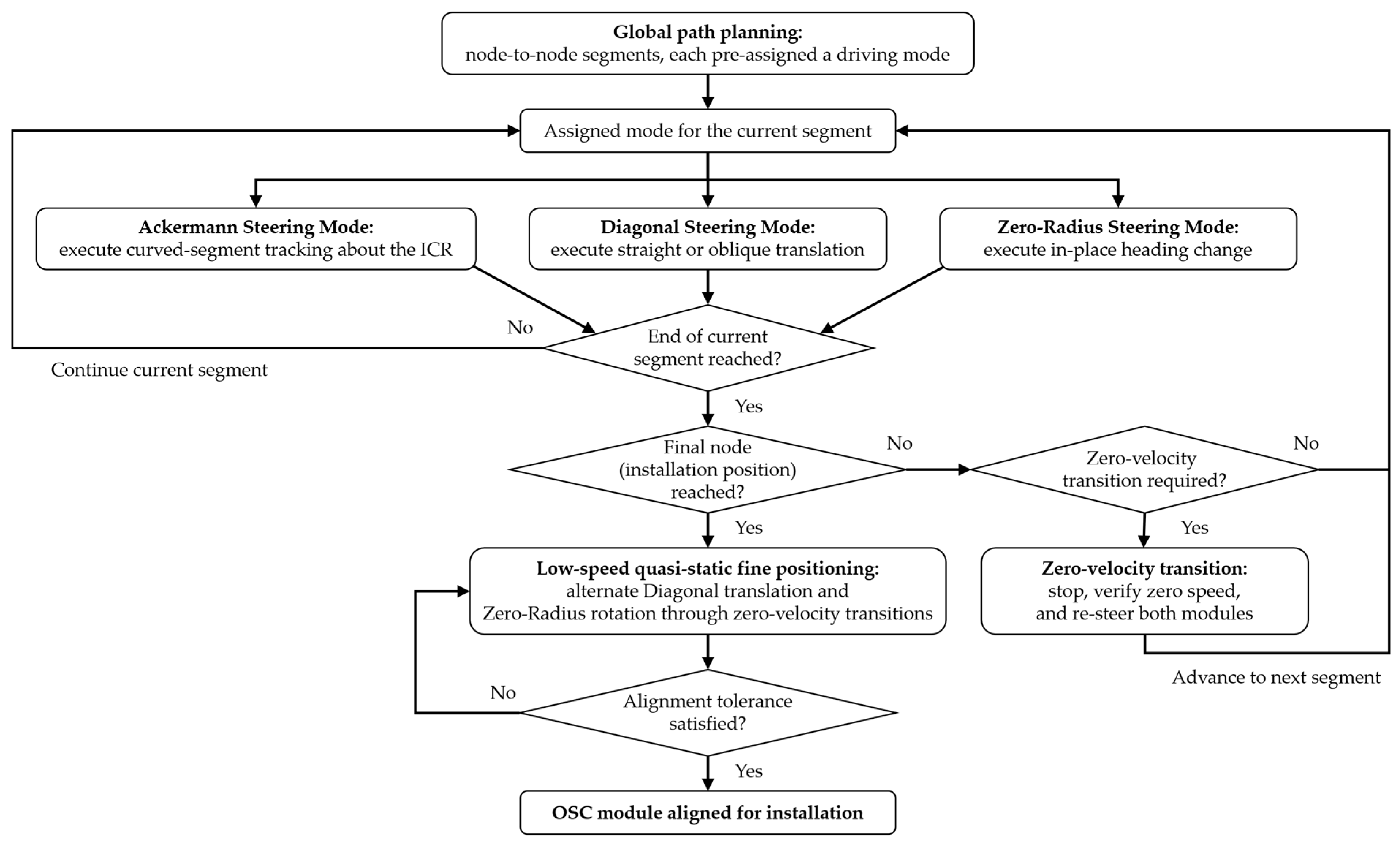
The local layer converts the global path into module commands executable under the platform’s kinematic constraints, and the hierarchical trajectory-tracking control of 4WIS/4WID platforms corresponds to this stage [24,25,26]. This layer generates trajectories within the constraint subspace of the mode assigned to each segment, sequences the transitions between modes, and inserts the Zero-Radius Steering Mode, which handles attitude alignment, between macro-transport segments. In the deployed system, these Zero-Radius segments and the associated transition points are likewise fixed at the planning stage, so that the complete segment-wise mode sequence of a path is determined in advance. Because the Zero-Radius Steering Mode rotates the body in place without translation to align the heading, it enables a change in direction even in a confined space [21], and it is used to orient the body in the direction required by the subsequent macro-transport mode when driving begins or to set the final heading after arriving at the goal position. Therefore, a typical operation proceeds by first aligning the heading with the Zero-Radius Steering Mode, then traversing the path with the Ackermann or Diagonal Steering Mode, and finally, after arriving at the installation position, performing fine alignment by combining Diagonal translation for position correction with Zero-Radius rotation for the final heading. The motion freedom, ICR, and layer roles of the three modes are summarized in Table 5, and Figure 5 shows how the driving mode pre-assigned to each path segment is executed, how the zero-velocity transitions are sequenced between segments, and how the platform is finally aligned at the installation position.
Because each mode requires a different steering geometry, mode transition involves the re-steering of modules. As shown in Section 4.1, performing this re-steering during motion produces a kinematic model mismatch, and forcing a continuous model at the mode boundaries produces an ICR discontinuity. To avoid these limitations, the proposed strategy performs mode transitions at zero velocity. That is, when the platform stops, each module is realigned to the steering angle of the new mode, and driving resumes. Because the drive wheels do not roll, the instantaneous steering angle inconsistency during the re-steering does not lead to stress or slip. Because the transition is treated as a discrete event in the stopped state and does not require a continuous ICR trajectory, the singularity associated with the ICR discontinuity is avoided. Above all, on a multi-ton platform carrying an elevated payload, the uncommanded drift that such inconsistencies would otherwise cause is a safety hazard: it can erode the tip-over margin and endanger nearby workers. The zero-velocity transition removes this hazard at its source, in addition to preventing the repeated in-plane stress quantified in Section 5.3 and the accumulation of odometry error.

4.3. Forward and Inverse Kinematics for Each Mode

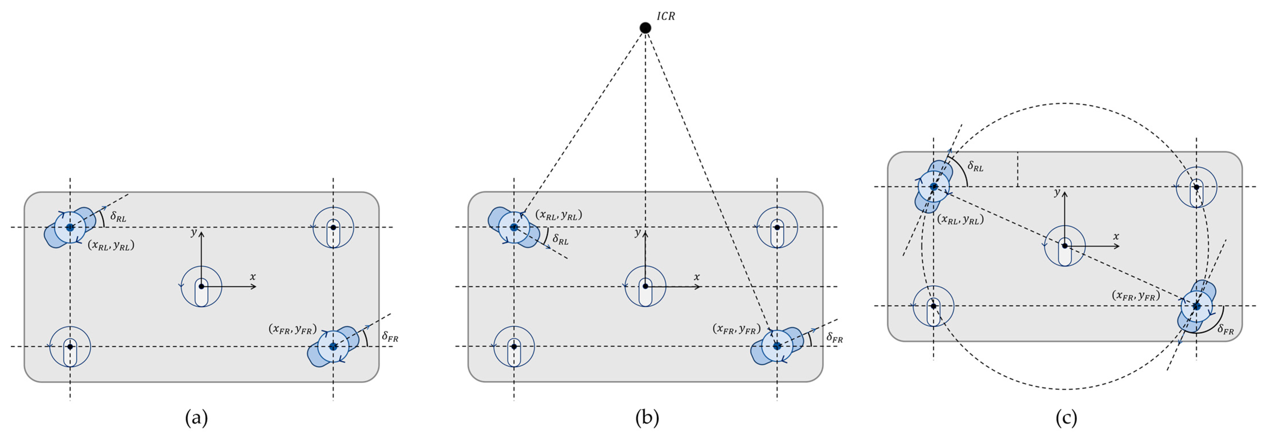
The kinematic formulation in this section builds on the established 2-SWD framework of Tagliavini et al. [16] and on the pseudoinverse-based twist recovery introduced for conventional-wheel holonomic vehicles by Wada and Mori [20]. Equations (3)–(6) restate these known relations in the notation of the proposed platform. Accordingly, the per-mode closed forms below are specializations of these relations, provided for implementation and odometry rather than as a theoretical contribution. The contribution is the three-mode driving strategy itself. This subsection derives the kinematics of the three driving modes in closed form in the body-fixed coordinate frame. The steering geometry of the two active modules in each mode is shown in Figure 6. All three geometries are defined on a five-point arrangement consisting of two active modules on one diagonal and three passive casters on the other diagonal and at the center, and only the two active modules are steered. In the Diagonal Steering Mode (Figure 6a), the two modules are aligned in parallel at the same steering angle so that the body translates without rotation, and in the Zero-Radius Steering Mode (Figure 6c), the two modules are aligned tangent to a rotation circle centered on the body center so that the body rotates in place. In the Ackermann Steering Mode (Figure 6b), the steering axes of the two modules meet at a point on the lateral axis to form the ICR, about which the body turns. Because the two modules lie at different distances from the ICR, they are driven at different steering angles and wheel speeds.
The planar motion of the body is described by the twist ( x ˙ , y ˙ , ω ) , where x ˙ and y ˙ are the translational velocities in the forward and left directions of the body frame, respectively, and ω is the yaw angular velocity. Of the two active modules on one diagonal, the front-right (FR) module is located at a , b and the RL module is located at a , b , where a is the longitudinal distance and b is the lateral distance from the body center to the module. Each module i { F R , R L } is commanded by a steering angle δ i and wheel speed v w , i .
In rigid-body kinematics, the ground contact-point velocity of module i is determined from the body twist [16], and in matrix form, it is as follows:
v F R , x v F R , y v R L , x v R L , y = M x ˙ y ˙ ω , M = 1 0 b 0 1 a 1 0 b 0 1 a
Resolving into components gives v F R , x = x ˙ + ω b , v F R , y = y ˙ + ω a , v R L , x = x ˙ ω b , and v R L , y = y ˙ ω a . The steering angle and wheel speed of each module are obtained from the contact-point velocity components as
δ i = atan 2 v i , y , v i , x , v w , i = v i , x 2 + v i , y 2
Forward kinematics. The forward kinematics recovers the body twist from the measured module states δ i and v w , i . The contact-point velocity components are obtained as v i , x = v w , i c o s δ i and v i , y = v w , i s i n δ i ; because the four components imposed by the two active modules over-determine the planar 3-DoF twist, a solution that exactly satisfies Equation (3) with a single twist generally does not exist. Therefore, the twist is recovered by the pseudoinverse in the least-squares sense [20]:
x ˙ y ˙ ω = M M 1 M v F R , x v F R , y v R L , x v R L , y
Here, since M M = d i a g ( 2 , 2 , 2 ( a 2 + b 2 ) ) , the recovery equations become
x ˙ = 1 2 v F R , x + v R L , x , y ˙ = 1 2 v F R , y + v R L , y , ω = b v F R , x v R L , x + a v F R , y v R L , y 2 a 2 + b 2
Inverse kinematics. Inverse kinematics converts the commanded body twist into the steering angle and wheel speed of each module. Substituting the contact-point velocities of Equation (3) into Equation (4) under the motion constraint of each mode yields a closed-form solution for each mode.
Diagonal Steering Mode. This is a pure translation mode with ω = 0 , and the contact-point velocities of the two modules are identical, ( x ˙ , y ˙ ) . Therefore, the two modules are steered in parallel in the same direction and driven at the same speed.
δ F R = δ R L = atan 2 y ˙ , x ˙ , v w , F R = v w , R L = x ˙ 2 + y ˙ 2
Ackermann Steering Mode. This is an arc-driving mode with no lateral velocity; therefore, y ˙ = 0 , and the contact-point velocities are v F R = ( x ˙ + ω b , ω a ) and v R L = ( x ˙ ω b , ω a ) . The two modules have different steering angles and speeds.
δ F R = atan 2 ω a , x ˙ + ω b , v w , F R = x ˙ + ω b 2 + ω a 2
δ R L = atan 2 ω a , x ˙ ω b , v w , R L = x ˙ ω b 2 + ω a 2
Here, the steering axes of the two modules meet at a point on the lateral axis to form the ICR, and the turning radius of the body center is R B C = x ˙ / ω .
Zero-Radius Steering Mode. This is an in-place rotation mode with no translation; therefore, x ˙ = y ˙ = 0 , and the contact-point velocities are v F R = ( ω b , ω a ) and v R L = ( ω b , ω a ) . The two modules are steered perpendicular to the radius toward the body center, that is, tangent to the rotation circle, and, being equidistant from the center, are driven at the same speed.
δ F R = atan 2 ω a , ω b , δ R L = atan 2 ω a , ω b , v w , F R = v w , R L = ω a 2 + b 2
Because the two modules are symmetric about the body center, their steering angles differ by π , and the wheel speed is proportional to the distance a 2 + b 2 from the center of the body.

4.4. Physical Assumptions of the Kinematic Model

The closed-form models derived in this section rest on three physical assumptions. First, the chassis behaves as a rigid body, so that the geometric parameters a and b that locate the two active modules remain constant under load. Second, all five support points maintain contact with the floor, so that the commanded steering angles and wheel velocities are realized at the ground. Third, the in-plane forces transmitted through the chassis remain bounded, which corresponds to the no-slip rolling condition and is enforced operationally by the zero-velocity mode transitions of Section 4.2. Section 5 examines whether the physical platform satisfies these assumptions at the rated operating point.

5. Structural and Hardware Validation

Section 4 derived the kinematic models under three physical assumptions (Section 4.4): a rigid chassis, maintained wheel-ground contact, and bounded in-plane forces. This section verifies these assumptions and the associated torque demands on the physical platform at the 6 t/8 m operating point. Section 5.1 confirms that the traction, steering, and lift motors deliver the torques implied by the kinematic commands under the rated load. Section 5.2 shows that the maximum chassis deflection under the maximum payload is 1.62 mm, small enough to preserve the geometric parameters of the kinematic model on the structured, even floors of the target domain (the rigid-chassis assumption), and that the five-point support lowers the peak stress and deflection relative to a four-point layout, consistent with the load-distribution rationale of Section 3.2 (the ground-contact assumption). The quantitative FEA results for the four load cases are summarized at the end of Section 5.3.

5.1. Motor Torque Analysis

In this subsection, the torque demands of the three types of active motors of the platform, that is, the traction, steering, and lift motors, are calculated, and the validity of the motor selection is verified by comparing the results with the operating data measured at the front and rear motors of the prototype. The torque of each motor was calculated from the load imposed by the operating point using static and dynamic relations based on free-body diagrams. The calculated total required torque was divided by the number of motors and gear ratio to convert it into the required torque per motor, which was then compared with the rated and measured torque of the selected motor. However, the prototype measurements were obtained over a representative operating cycle rather than under the specified maximum operating conditions used as the calculation basis at the design time (maximum payload, speed, and acceleration); therefore, the measured torque was not the peak of the worst-case condition. Accordingly, the adequacy of the motor for the specified maximum condition was judged by comparing the calculated required torque with the rated torque, and the measured data were used as the basis for confirming that the motor actually exhibited the torque behavior assumed by the calculation equations and operated stably. Section 5.1.1 addresses the traction motor, and Section 5.1.2 and Section 5.1.3 address the steering and lift motors, respectively.

5.1.1. Traction Motor Torque

The traction motors supply the driving force required for the platform to drive and accelerate at the target speed while carrying a 6 t payload on a structured, even floor. The total torque required for traction, T total , is calculated by multiplying the sum of the constant-speed torque on level ground, T f , the constant-speed torque on an incline, T i , and the torque required for acceleration, T a , by a safety factor S f ; this is based on the established method of sizing the traction motor of a mobile robot from the sum of the rolling resistance, incline, and acceleration components [34]. The calculation proceeds from the following force and torque relationships:
The total mass of the platform, M total , is the sum of the platform self-weight M a and the payload M p (Equation (11)), and a specified maximum payload M p = 6 t is applied in the calculation.
M t o t a l = M a + M p
Because the rolling resistance opposing constant-speed driving is proportional to the normal force perpendicular to the floor, it is obtained from Equation (12) using the rolling-resistance coefficient μ , the incline angle θ ; the gravitational component along the slope on an incline is obtained from Equation (13). Here, g is the gravitational acceleration, and θ is the floor incline angle.
F f = μ · M t o t a l · g · cos θ
F i = M t o t a l · g · sin θ
The wheel-axle torque required for constant-speed driving on level ground and on an incline is calculated from Equations (14) and (15) by multiplying each force, F f and F i , by the wheel radius ( d / 2 ) and dividing by the drivetrain efficiency (motor and gearbox efficiency) η .
T f = d 2 · F f η
T i = d 2 · F i η
The torque required for acceleration, T a , is the torque needed to accelerate the entire rotating and translating inertia at the target angular acceleration; it is calculated by multiplying the angular acceleration by the sum of the wheel moment of inertia J w , motor moment of inertia J m , and the term converting the translational mass M total into an equivalent inertia at the wheel axle (Equation (18)). The wheel moment of inertia is given by Equation (16) as a disk approximation in terms of the wheel weight M w and diameter d , and the motor moment of inertia J m and drivetrain efficiency η are taken from the motor and gearbox datasheets. The wheel rotational speed Δ R corresponding to the target maximum speed v is given by Equation (17), and the condition of accelerating from 0 to Δ R during the acceleration time Δ t a is applied to the system.
J w = M w · d 2 8
R = 60 π · v d
T a = J w + J m + M t o t a l η · d 2 4 · π 30 · R t a
The three torque components are summed and multiplied by the safety factor S f to calculate the total torque required for traction, T total (Equation (19)), which is divided by the number of traction motors N and gear ratio G to convert it into the required torque per motor, T m (Equation (20)). This study applies S f in the range of 1.2–1.5. The gearbox is selected by considering its allowable torque relative to the required torque, the motor rated speed relative to the target maximum speed, and the allowable load.
T t o t a l = T f + T i + T a · S f
T m = T t o t a l N · G
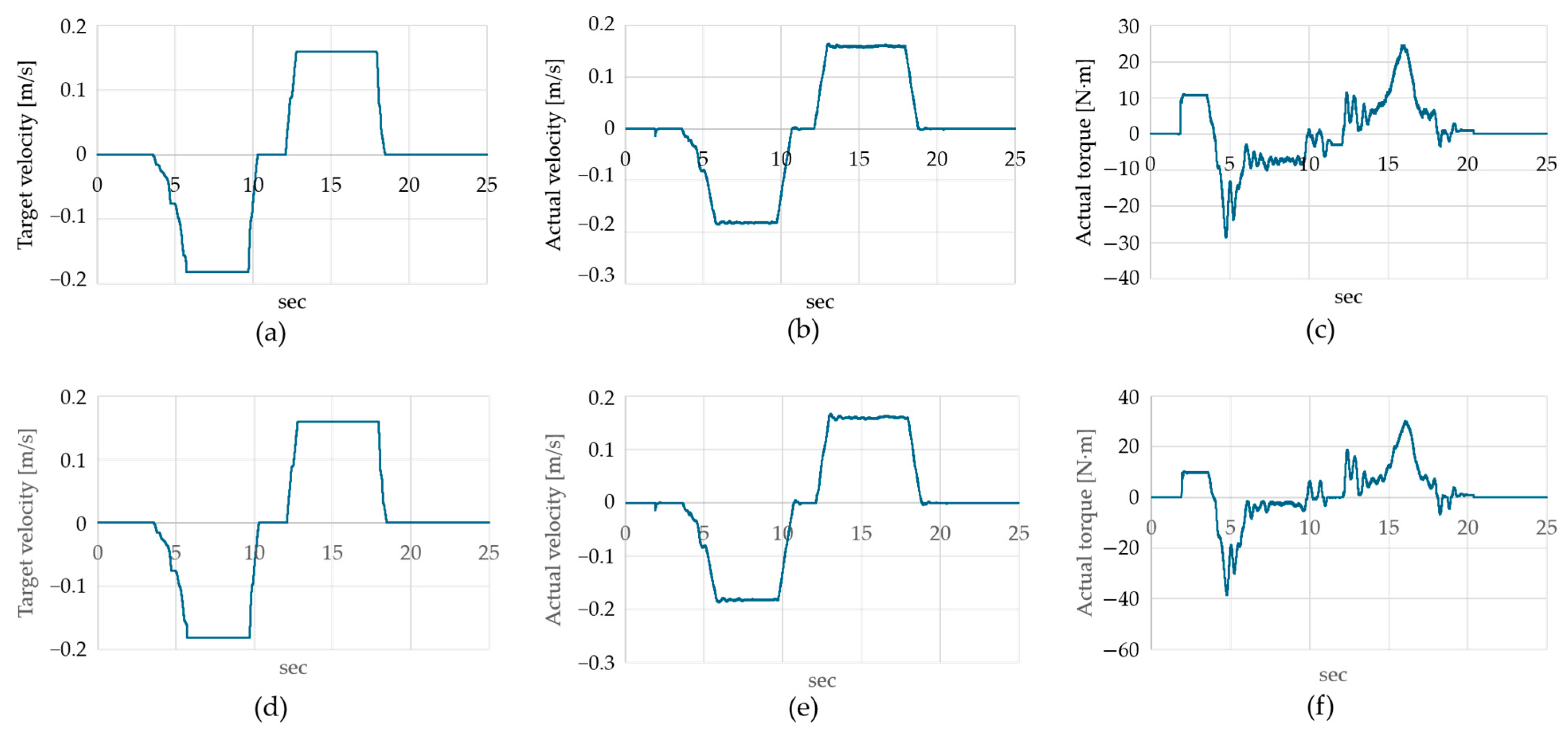
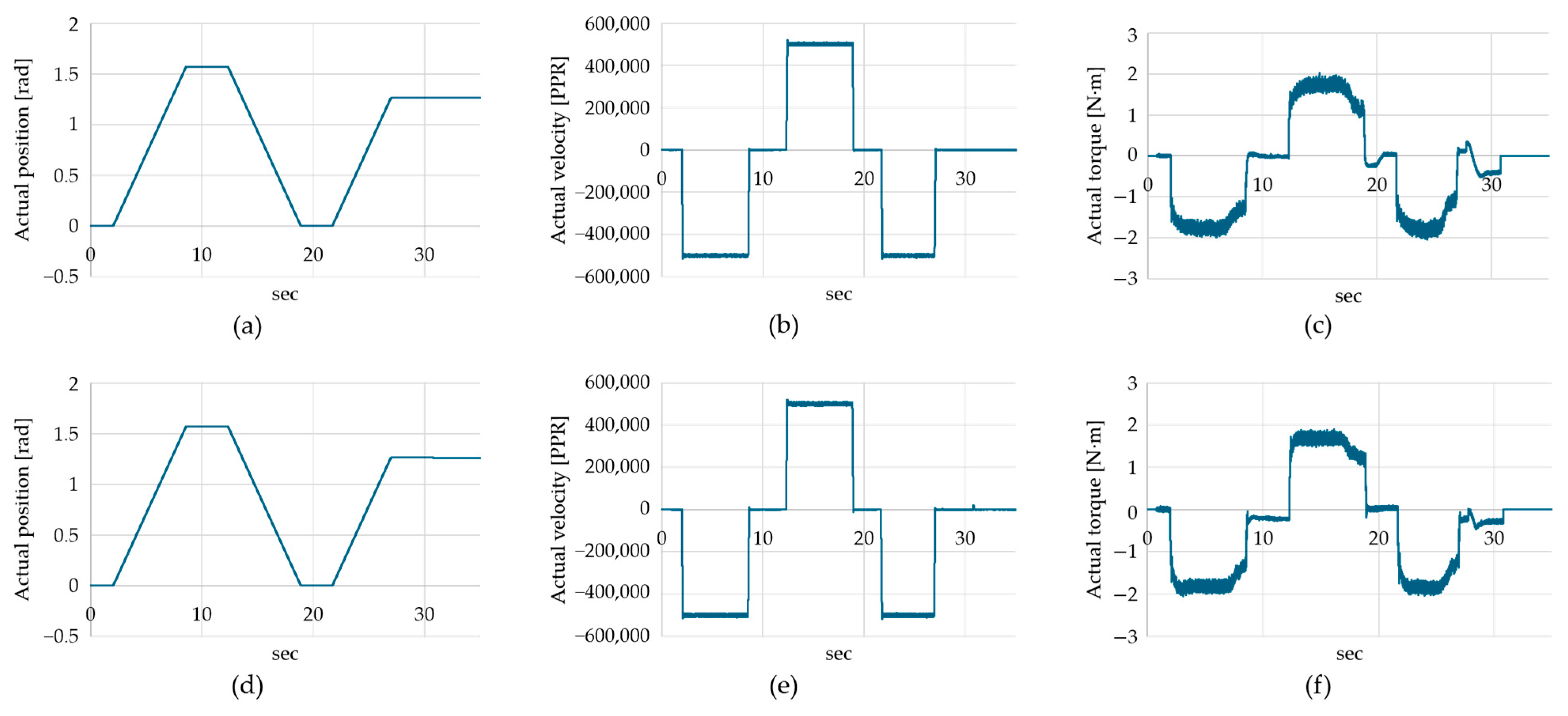
The validity of the calculation procedure was confirmed using measured data from the prototype traction motors. Figure 7 shows the target velocity, actual velocity, and actual torque measured over time for the two traction motors during a drive cycle, including forward and reverse motions. The actual velocity of both motors closely tracked the target velocity, so the traction control achieved the target bidirectional driving performance, and the torque behaviors of the two motors were similar, showing that the load sharing between the 2-SWD modules was balanced. The actual torque rose to a peak in the transient interval, including acceleration, and remained at a lower level in the constant-speed interval, which showed that the acceleration torque (Equation (18)) outweighed the constant-speed resistance torque (Equations (14) and (15)) in the torque demand, indicating that the measurement results were consistent with the structure of the calculation equations. The fact that both motors stably performed bidirectional operations, including acceleration and deceleration, experimentally confirmed that the traction motors sized and selected using Equations (11)–(20) met the loaded target-speed operating condition.

5.1.2. Steering Motor Torque

The steering motors rotate the swerve modules about their steering axes to form the module orientations required for three-mode driving. Because the torque required for steering is greatest under the stationary-steering condition, in which the orientation is changed while the wheel is stopped [35], this study used this condition as the calculation basis. The stationary steering torque is calculated as the sum of the scrub torque T scrub , which arises as the contact patch twists against the ground, the acceleration torque T α required to angularly accelerate the steering assembly, and the internal friction torque T b of the steering bearing.
When the module turns about the steering axis at rest, the entire contact patch slides against the ground and forms a frictional moment. If the contact patch is approximated as a circular patch of uniform pressure, the scrub torque is obtained by integrating the friction force per unit area over the moment arm (Equation (21)). Here, F z is the vertical load on the wheel, a is the contact patch radius, and μ s is the tire–road sliding friction coefficient; μ s is larger than the rolling-resistance coefficient of Section 5.1.1 and takes a separate value. When the payload is large, the contact patch approaches a rectangle; therefore, the accuracy can be improved by applying a rectangular-patch integration or a corrected empirical formula [35].
T s c r u b = 2 3 · μ s · F z · a
The torque T α required to accelerate the steering assembly (the wheel, fork, and reflected motor inertia) at the steering angular acceleration is calculated from Equation (22) by multiplying the steering-part moment of inertia about the steering axis J s by the steering angular acceleration α s . The angular acceleration is set as α s = ( π / 30 ) ( Δ n s / Δ t s ) in terms of the steering rotational-speed change Δ n s and the acceleration time Δ t s , which is the same relation as the acceleration torque term in Section 5.1.1. J s is taken from the datasheet.
T α = J s · α s = J s · π 30 · Δ n s Δ t s
The internal friction torque T b when the slewing bearing supporting the steering part rotates under a vertical load is calculated from Equation (23) using the bearing friction coefficient μ b and mean radius r b ; more precisely, the friction torque value from the bearing datasheet is used.
T b = μ b · F z · r b
The gravitational aligning torque arising from the kingpin inclination and scrub radius is negligible because the steering axis of the platform is a vertical axis passing through the center of the contact patch.
The three components are summed and multiplied by the safety factor S f to calculate the total torque required for steering, T steer (Equation (24)), which is divided by the gear ratio G and drivetrain efficiency η to convert it into the torque per motor, T m (Equation (25)). Unlike the traction motors, each steering motor is responsible for only its own module; therefore, the torque is not distributed by the number of motors, and the efficiency η is reflected in the reduction conversion step. Typically, the stationary scrub torque is the dominant term, and the slower the steering, the smaller the contribution of the acceleration torque to the total steering torque. In addition, because the reaction torque of the traction motor under a large acceleration tends to rotate the steering axis, the steering motor is selected to provide the holding torque against this reaction.
T s t e e r = T s c r u b + T α + T b · S f
T m = T s t e e r G · η
The validity of the calculation procedure was confirmed using measured data from the prototype steering motors. Figure 8 shows the actual angular position, angular velocity, and torque measured over time for the two steering motors during a steering cycle that changed the module orientation. The actual angular position closely tracked the commanded steering angle; therefore, the steering control achieved the target orientation, and the behaviors of the two motors were similar, showing that the steering load between the 2-SWD modules was balanced. The actual torque maintained a low, flat level whose sign followed the steering direction during the interval in which the steering proceeded and dropped to near zero when the module was stopped and held at a particular orientation. This showed that the steering torque was dominated by the contact-patch scrub torque (Equation (21)) during steering and that little torque was required to hold the orientation, which was consistent with the present configuration in which the steering axis passes through the center of the contact patch and the gravitational aligning torque is neglected (the treatment in Equation (24)). Moreover, the fact that the torque was flat in the steering interval without a pronounced peak from acceleration and deceleration supported the calculation premise that the contribution of the acceleration (inertia) torque term (Equation (22)) is small and that the scrub torque is the dominant term. Both steering motors stably performed the steering cycle, experimentally confirming that the motors sized and selected using Equations (21)–(25) met the steering performance requirements.

5.1.3. Lift Motor Torque

The lift motors drive the helical band actuators to raise a 6 t payload to a lift height of 8 m. The helical band actuator is a device in which two interlocking steel bands form a rigid telescopic column and convert the rotation of the motor into vertical lifting [32]; the axial lift force and drive torque are linked through the effective lead, that is, the column rise per rotational input. Because the four scissor mechanisms handle only lateral stabilization rather than lifting, the entire lift load is supported by the helical band actuators. The platform uses four actuators, and because one lift motor drives two actuators, there are two lift motors.
The force required for lifting is the sum of the gravitational force acting on the total mass of the lift unit M L and the inertial force owing to the lift acceleration. Assuming that this is shared equally by the four actuators, the lift force per actuator is given by Equation (26). Here, M L is the sum of the specified maximum payload M p = 6 t and the self-weight of the lift structure, a L is the lift acceleration, and N act is the number of actuators.
F a = M L · g + a L N a c t
The drive torque of the helical band actuator, which converts rotation into vertical lifting, is calculated from the spindle (screw) relation using the effective lead p (the column rise per revolution of the actuator drive shaft) and mechanism efficiency η s , as shown in Equation (27). This is the torque per actuator drive shaft required to lift axial force F a .
T a c t = F a · p 2 π · η s
Because one lift motor drives N m = 2 actuators together, the torque borne by one motor is N m times the drive torque per actuator. This is multiplied by the safety factor S f and divided by the gear ratio G and gearbox efficiency η g to convert it into the required torque per motor, T m (Equation (28)). Because the helical band actuator is a rigid mechanical device, unlike a hydraulic actuator, it does not require a continuous holding torque to support the load at rest; however, a braking means for safe holding is considered separately.
T m = N m · T a c t · S f G · η g
Because raising works against gravity, the required torque is large, whereas lowering is assisted by gravity and requires less torque than raising. Therefore, the worst-case condition for motor selection is the raising interval, including acceleration.
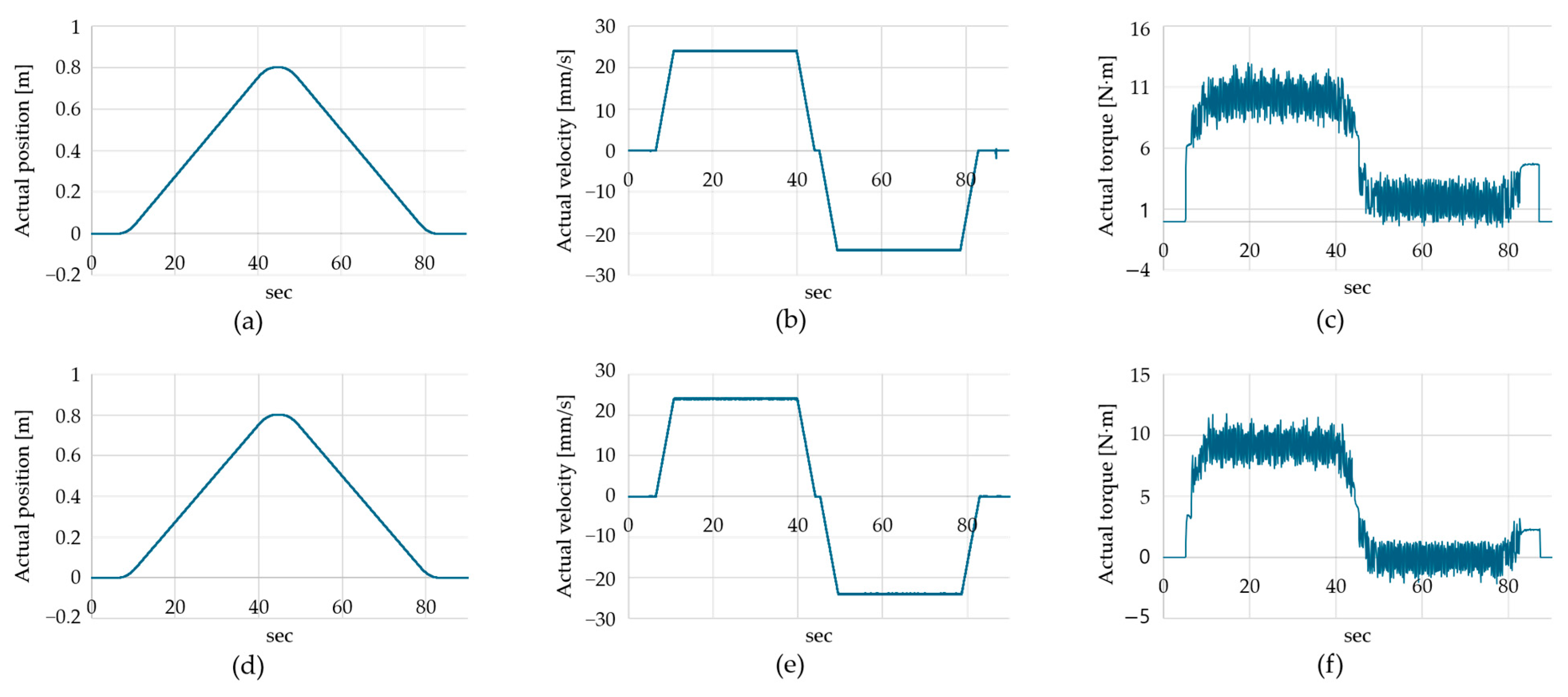
The validity of the calculation procedure was confirmed using measured data from the prototype lift motors. Figure 9 shows the actual position, velocity, and torque measured over time for the two lift motors during a lift-and-lower cycle. The actual position rose and returned smoothly, and the actual velocity maintained a constant value in the steady raising and lowering intervals. Therefore, the lift control achieved the target behavior, and the behaviors of the two motors were similar, indicating that the lift load between the two motors was balanced. The actual torque maintained a steady value in the raising interval and dropped to a markedly lower level in the lowering interval, which reflects the difference between raising, which lifts against the gravitational load, and lowering, which is assisted by gravity, indicating that the gravitational lifting term in Equations (26) and (27) dominated the torque. The fact that the torque was flat in both the steady raising and lowering intervals and had no pronounced peak from acceleration and deceleration was consistent with the calculation premise that the lift acceleration is small and that the contribution of the acceleration term in Equation (26) is negligible. Both lift motors stably performed the lift-and-lower cycle, experimentally confirming that the lift motors sized and selected using Equations (26)–(28) met the loaded lifting operating condition.

5.2. Chassis FEA Under Maximum Payload

FEA was performed to quantitatively validate the structural integrity of the chassis. Because this subsection and Section 5.3 share the same material model, mesh, analysis procedure, and factor-of-safety definition, the common methodology is described together in this subsection. The FEA settings are summarized in Table 6, and the analysis was performed using SolidWorks Simulation 2025 SP5.0 (Dassault Systèmes, Vélizy-Villacoublay, France). The FOS is defined, according to the yield criterion for a ductile material, as the ratio of the yield strength to the equivalent stress (Equation (29)), and this study considers FOS ≥ 2.0 under the maximum-payload condition as the design criterion for the chassis. The kinematic-mismatch load cases of Section 5.3 are not part of this sizing criterion; their purpose is to quantify the mismatch-induced in-plane stress.
F O S = σ y i e l d σ v o n M i s e s
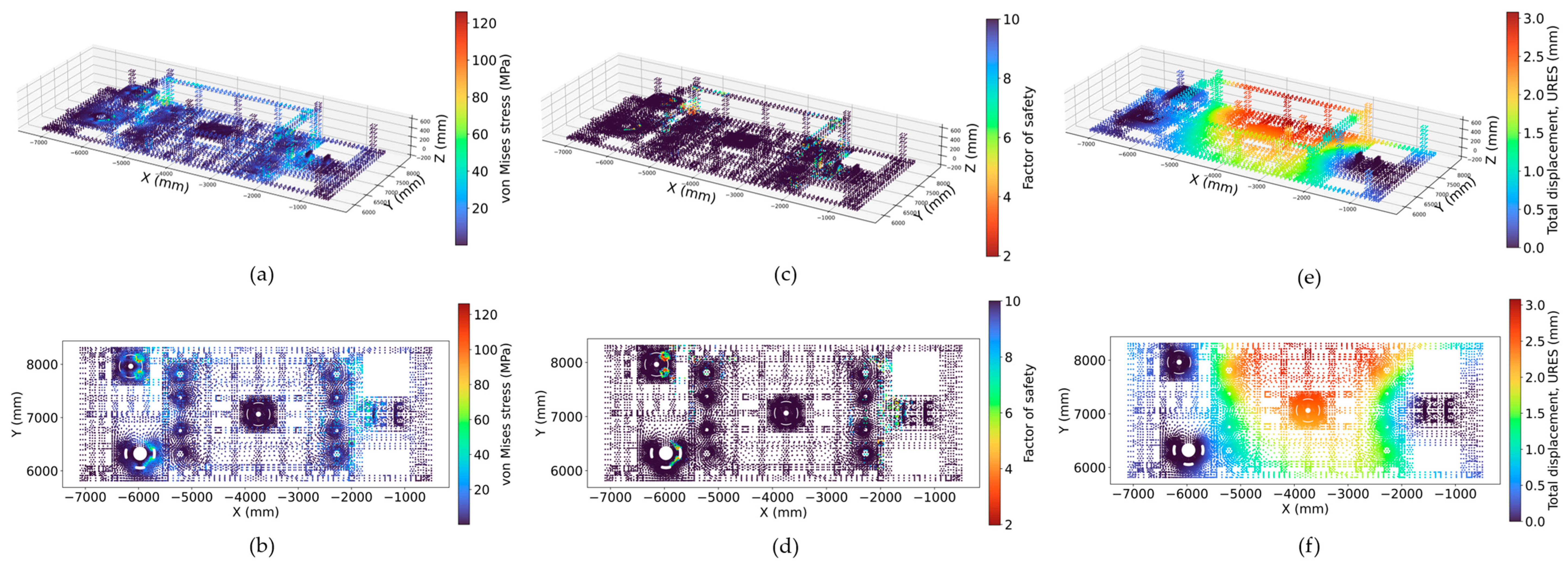
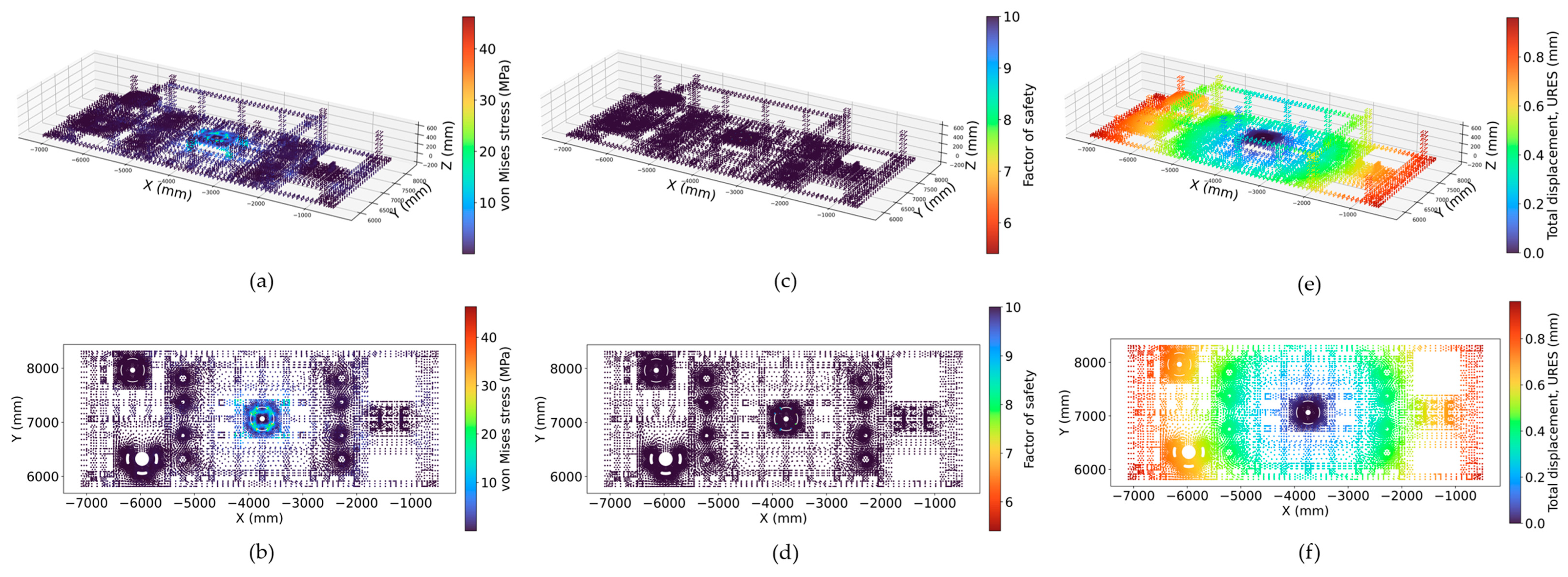
The analysis results present the distributions of the von Mises stress, resultant displacement (URES), and FOS in node-cloud and top-view (X–Y) representations.
As boundary conditions, the regions where the traction and steering modules and casters are mounted to the chassis were fixed-constrained, and the distributed mass load of the lift unit was applied to the four regions where the helical band actuators were fixed. This distributed load was calculated as the lift-unit mass (kg), the sum of the maximum payload weight, top-plate weight, and one-half of the scissor weight. To this, gravity and an inertial load (N), obtained as the same mass multiplied by the lift acceleration, were added in the same regions to reflect the load increase at the instant of lift initiation.
The analysis was performed for two cases with different support configurations: the first is a five-point support including the center caster, and the second is a four-point support excluding the center caster. The four-point case is analyzed as an ablation that isolates the structural contribution of the center support and as a bounding case for the condition in which the center caster carries no load.
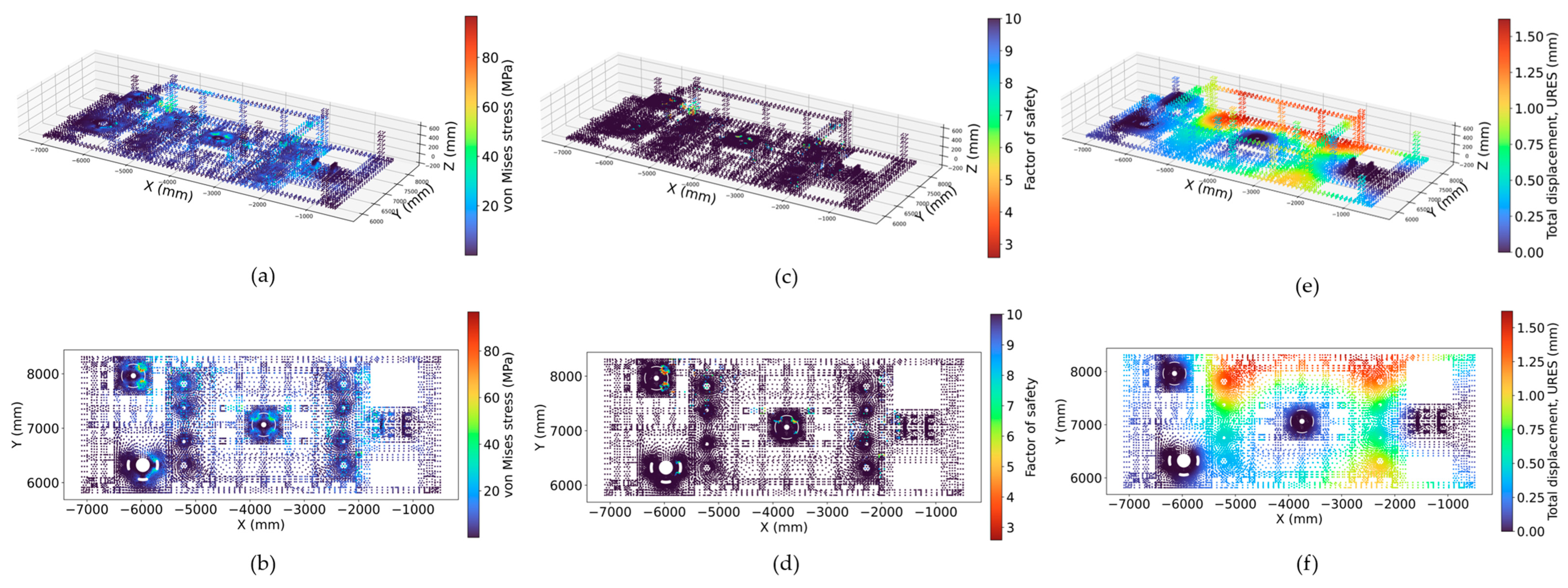
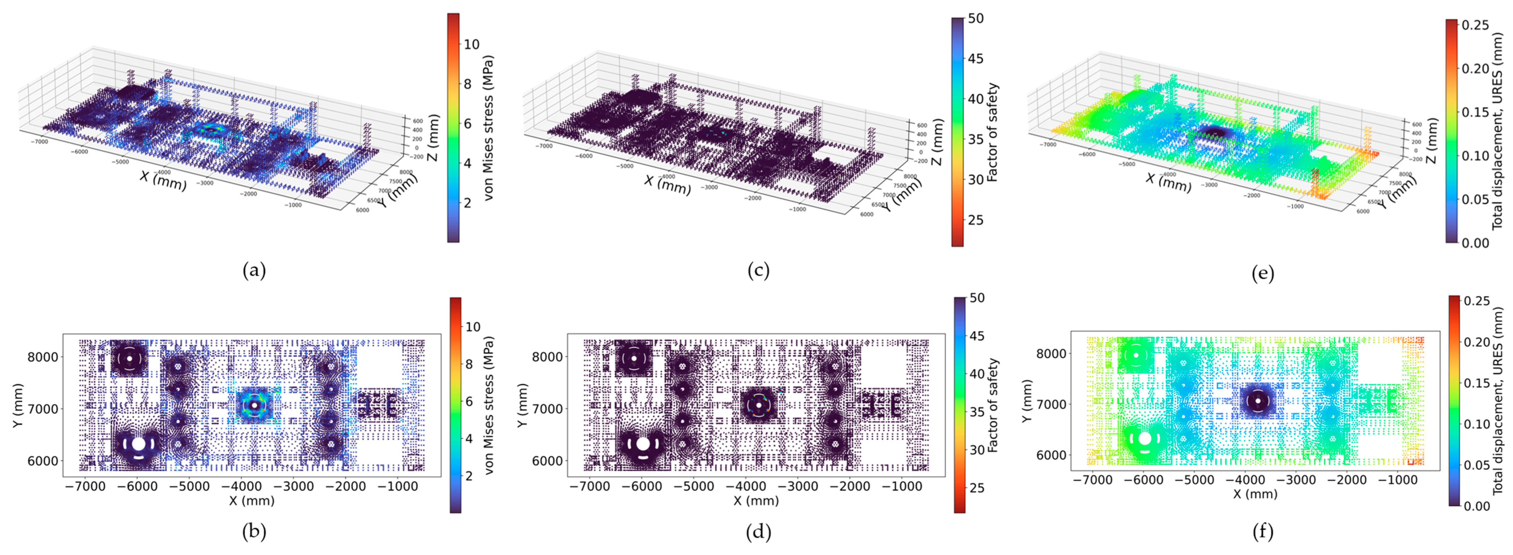
Figure 10 and Figure 11 show the distributions of the von Mises stress, FOS, and resultant displacement for the five-point and four-point supports, respectively, in node-cloud and top-view representations. The four-point support has a larger maximum equivalent stress and maximum resultant displacement and a lower minimum FOS than the five-point support because removing the center caster lengthens the unsupported span at the chassis center and increases bending stress and deflection. In contrast, with the five-point support, the center caster supports the central part, and the stress and displacement decrease markedly. A five-point support configuration was adopted in the proposed platform. Under the maximum payload and maximum lift conditions, it produced a maximum von Mises stress of 96.68 MPa and a maximum resultant displacement of 1.62 mm; relative to the SS400 yield strength of 245 MPa, this corresponds to a minimum FOS of 2.59, satisfying the design criterion and confirming the structural integrity of the chassis. In the four-point bounding case, the maximum von Mises stress rises to 126.1 MPa and the minimum FOS falls to 1.98: the chassis remains elastic, but the design criterion is met only with the five-point support. This establishes the center support as a design requirement rather than an optional reinforcement. Table 7 reports the vertical reaction force at each support point obtained from the finite element solution under the maximum-payload condition, with the bogie-coupled pair reported as a single combined reaction. The four-point case of Figure 11 bounds the redistribution toward the outer supports when the center caster is partially or fully unloaded, as on a locally uneven floor.

5.3. Chassis FEA Under Kinematic Mismatch

This subsection uses FEA to quantify the in-plane stress induced in the chassis by the kinematic mismatch. As diagnosed in Section 4.1, a mode transition during motion transmits incompatible module velocities to the chassis as in-plane reaction forces, and because the transition is repeated every operating cycle, this stress becomes a primary cause of chassis fatigue failure. Because the zero-velocity mode transition in Section 4.2 removes this mismatch at the moment of transition and thereby eliminates the cause of the repeated stress itself, the analysis in this subsection quantifies the magnitude of the stress that the zero-velocity transition avoids, while also confirming that the chassis remains below yield even for a single in-plane reaction force that may remain due to synchronization error or similar issues. Except for the load conditions, the material, mesh, analysis procedure, and FOS definition were the same as those in Section 5.2.
As boundary conditions, the chassis center was fixed-constrained, and the force transmitted from the wheels to the chassis, based on the maximum payload weight, was calculated with static friction as the upper bound and then applied as an in-plane load (N) in the regions where the traction and steering modules were fixed, with gravity added. Because the static friction upper bound corresponds to the maximum horizontal force transmissible just before the wheel slips, it provides a conservative upper bound on the in-plane reaction force that can be induced by the kinematic mismatch.
The analysis was performed for two cases with different load directions. The first is left-right loading, in which a rightward load is applied at the front-right region, where the traction and steering module is fixed, and a leftward load at the rear-left region. The second is front-rear loading, in which a forward load is applied at the front-right region and a rearward load is applied at the rear-left region. The two cases simulate the opposing in-plane reactions exerted by the two diagonally placed traction and steering modules on the chassis when the modules are misaligned laterally or longitudinally.
Figure 12 and Figure 13 show the distributions of the von Mises stress, FOS, and resultant displacement for left-right loading and front-rear loading, respectively, as node-cloud and top-view representations. In both cases, the in-plane reaction owing to the kinematic mismatch induced a clearly measurable equivalent stress in the chassis: the left-right case produced a maximum von Mises stress of 46.26 MPa (minimum FOS 5.4, maximum URES 0.96 mm), and the front-rear case produced 11.54 MPa (minimum FOS 21.67, maximum URES 0.26 mm) (Table 8). This stress corresponds to the repeated stress that the zero-velocity transition avoids in every operating cycle. As stated in Section 5.2, these load cases are not part of the sizing criterion; the FOS values are reported as a supplementary observation confirming that the chassis remains below yield with a substantial static margin, even for a single in-plane reaction occurring under the conservative condition of the static-friction upper bound.

6. Experimental Evaluation

This section reports the deployment of the proposed platform at actual OSC sites to quantitatively validate its utility. As established in Section 1 and Section 2.1, the absence of a single platform that meets the three-requirement combination forces sites to deploy multiple machines and the accompanying operating and working personnel for each installation. The two field cases that follow, conducted under different operating conditions, show the productivity changes observed when the proposed platform replaced this multi-machine, multi-worker process with a single machine.

6.1. Field Deployment Overview

The productivity analysis in this section is structured by performing the piping OSC module installation at each site in two ways: the conventional method applied at that site and the proposed platform-based method, and comparing the results on the same metric axes. The comparison metrics were the three axes of labor input, equipment, and construction time. Labor input is classified by work role into manager, operator, signaler, pipefitter, and scaffolder. In each case, the baseline is the installation method that was actually in use at the corresponding site: the conventional on-site method in Case A and the equipment-based OSC method in Case B. Each comparison is therefore made against the incumbent practice under identical site conditions, rather than against a nominal or literature-derived reference; a controlled side-by-side comparison with alternative mechanized options was not feasible on the active sites, and this limitation is discussed in Section 6.4. This analysis was based on operational data collected at two construction sites in actual operation rather than under controlled laboratory conditions, thereby directly evaluating the industrial applicability of the proposed platform under field conditions.
The two sites were selected to jointly validate two different operating points inside the envelope defined by the rated operating range of the proposed platform, that is, a 6 t payload and an 8 m lift height. Case A represents a medium-lift condition with a module mass of approximately 3 t and an installation height of approximately 3 m, and Case B represents a high-lift condition with a module mass of approximately 2 t and an installation height of approximately 8 m, that is, an operating point corresponding to the rated lift height. Because both cases lie inside the rated envelope, the field validation in this section did not demonstrate the worst-case condition of simultaneously lifting a 6 t payload to a height of 8 m; rather, it validated the field applicability and productivity effect of the platform at two different operating points within the rated range.
However, because this analysis is based on two real-field cases, there is an inherent limitation in generalizing its results to all OSC module installation scenarios. Site-specific variables, such as module shape, site movement paths, and work-team proficiency, can affect productivity metrics, and the quantitative improvements presented in this section should be understood as values observed under the operating conditions of the two sites. Nevertheless, because the two cases occupy different operating points in the payload–lift-height plane, the consistent improvement trend across the two cases provides reasonable support for the industrial utility of the proposed platform.

6.2. Case A: Conventional Method vs. Proposed OSC Platform

Case A involved a piping installation task at a production plant construction site, comparing the conventional general method with the proposed platform-based OSC method. The conventional general method does not lift the piping in module units; instead, it loads individual pipes onto self-propelled scissor lifts, raises them to the installation height, and fastens them on-site. Because the process of handling pipes individually at a height is repeated, multiple scissor lifts and their operating personnel are deployed. Here, the forklift is used only during the pipe-receiving stage. In contrast, the proposed method prefabricates the piping off-site as a single module of approximately 3 t and then lifts and installs it as a batch with the proposed platform at an installation height of approximately 3 m. On-site module installation in the proposed method proceeds in seven steps, from receiving to chemical anchor fastening (Figure 14).
The process is as follows: first, the prefabricated piping module is brought to the site using a forklift (Step 1) and loaded onto the proposed platform for transportation to the installation point (Step 2). At this point, casters for transport have been attached in advance to the bottom of the module. The proposed platform then lifts the entire module to the target installation height (Step 3), and the casters that were attached for transport are removed (Step 4). Because the prefabricated piping module is not designed to be placed directly at the target height, a separately received base post is attached to support and fix the module lifted to the target height (Step 5). Next, the platform’s omnidirectional locomotion is used to position the module precisely at the installation location (Step 6); although the figure for this case illustrates the installation of a single module, in actual construction, multiple modules are installed side by side; therefore, this fine positioning for inter-module alignment is required. Finally, the aligned module is fixed in place using chemical anchors to complete the installation (Step 7).
Thus, whereas the conventional general method deploys multiple self-propelled scissor lifts for the repeated lifting and fastening of individual pipes, the proposed method replaces them with a single platform that lifts the entire module at once. The two deployments validate the practical applicability of the platform at two operating points inside its rated envelope (approximately 3 t at 3 m in Case A and 2 t at 8 m in Case B); they do not demonstrate the worst-case operating condition of a 6 t payload at an 8 m lift height. Table 9 presents a quantitative comparison of the labor input, equipment, and construction time of the conventional general and proposed methods.
The key change observed in Table 9 is the substantial reduction in the lifting equipment and its operating personnel. Whereas the conventional general method deploys four self-propelled scissor lifts and their operators to repeatedly lift and fasten individual pipes at a height, the proposed method lifts the entire module with one proposed platform and one operator. Consequently, the number of equipment units decreased from five to two (a reduction of 60%), and the number of operators likewise decreased from five to two (a reduction of 60%). Therefore, the total personnel required for the installation work decreased from 11 to 8 (approximately 27.3%). That is, by replacing the process of repeatedly lifting and aligning many pipes individually with the batch lifting of the entire module, not only is the labor input reduced, but the working time spent on repetitive, individual lifting is also shortened.
This efficiency gain in equipment and labor led directly to a reduction in construction time in this case. Whereas the conventional method required approximately 14 days, the proposed method completed the same task in 2 days, shortening the construction time to approximately one-seventh. However, because the conventional method in Case A involves the installation of individual pipes directly on site, the above improvement reflects the combined effect of piping modularization (off-site prefabrication) and batch lifting using the proposed platform. A comparison that separates the respective contributions of modularization and the platform is provided by Case B (Section 6.3), whose baseline is already an OSC-module method. In summary, Case A shows that, under the conditions of this site, the labor- and time-intensive bottleneck of on-site construction diagnosed in Section 2.1, namely the reliance on multiple machines and workers, was quantitatively reduced through modularization and replacement with a single platform.

6.3. Case B: Equipment-Based OSC vs. Proposed OSC Platform

Case B was conducted at another piping module installation site, where the target module has a mass of approximately 2 t and is installed at a height of approximately 8 m. This installation height corresponds to the proposed platform’s rated lift height of 8 m; thus, Case B represents the high-lift operating point of the two cases in this section. The conventional method at this site already adopts an OSC approach, but it lifts and installs prefabricated piping modules with chain blocks. In contrast, the proposed method replaces this manual lifting with a single lift by the proposed platform, and its on-site module installation proceeds in five steps, from receiving and staging to fastening (Figure 15). Here, the forklift is used only in the module-receiving stage.
The process is as follows: first, the prefabricated piping module is brought in by a forklift and staged (Step 1) and transported by the proposed platform to the installation point (Step 2). The proposed platform then raises the module to a target height of approximately 8 m using its own lifting function (Step 3) and positions it precisely at the installation location using omnidirectional locomotion (Step 4). Finally, the lifted and aligned module is fastened to the upper structure to complete the installation (Step 5).
Whereas Case A used a general method as its baseline, Case B differed in that its baseline was a method that already employed OSC equipment. Case B verifies whether the proposed platform has a productivity advantage not only over a general method but also over an existing OSC equipment combination. Table 10 presents a quantitative comparison.
The key change observed in Table 10 is the elimination of scaffolders deployed for manual lifting. Whereas the conventional OSC method deploys four chain blocks and four scaffolders operating them for manual lifting, the proposed method replaces this chain-block-and-scaffolder combination with one proposed platform and one operator, reducing the personnel deployed for lifting from four to one and removing all four chain blocks. In contrast, the configuration common to both methods remains unchanged: two self-propelled scissor lifts and their two operators, one forklift used for receiving, two pipefitters, one manager, and two signalers. Consequently, the total personnel decreased from 12 to 9 (a reduction of approximately 25.0%), and the equipment from seven units to four (a reduction of approximately 42.9%). The substitution effect of the proposed platform was concentrated in the manual lifting process, which was the most labor-intensive step in the conventional method.
This substitution halved the construction time: the proposed method completed in 9 days the same task for which the conventional OSC method required 18 days. This change has safety implications. Chain-block-based manual lifting requires the direct involvement of workers throughout the lifting process, and a process in which multiple workers manually handle heavy loads is directly linked to the major accident modes reported in industrial material handling [7,10]. Replacing this manual lifting process with the proposed platform reduced the personnel exposed to heavy manual work.
Considering the two cases together, the proposed platform, at two different operating points within the rated envelope, namely the medium-lift condition of Case A and the high-lift condition of Case B, replaced the multi-machine combination process and quantitatively reduced the deployed equipment, personnel, and construction time; these are observed improvements in the two tested cases. In particular, Case B, whose baseline is already an OSC-module method, shows the substitution effect of the platform itself, separated from the modularization effect, whereas Case A shows the combined effect of modularization and the platform. This is consistent with prior reports that modular construction can significantly reduce on-site labor and construction time relative to conventional on-site methods [2], and the field data support the proposed platform as a practical candidate for replacing the OSC module installation work of the existing multi-machine combination approach.

6.4. Discussion and Trade-Offs

The observed gains should be interpreted together with the following trade-offs. First, the zero-velocity mode transitions introduce dwell times into each work cycle. Because the driving mode of each path segment is pre-assigned at the planning stage, the number and locations of these transitions are fixed by the planned path. Although the transition time was not separately logged in the two deployments, the installation cycle time was dominated by lifting, fine positioning, and fastening; the fine positioning itself alternates Diagonal translation and Zero-Radius rotation, so the mode changes in this phase are part of the alignment process rather than an added overhead, and the remaining transition stops largely coincided with process-required stops for load checks. Quantifying this dwell time remains future work (Section 7.3). A continuous-mode alternative would remove this dwell time, but it would require traversing steering configurations in which the commanded module velocities are kinematically inconsistent. The uncommanded drift that such inconsistency would cause under a multi-ton elevated payload is, above all, a tip-over hazard to nearby workers. In addition, motion with the payload lifted is restricted to low-speed, quasi-static fine positioning; the coupled dynamics of simultaneous lifting and driving is outside the scope of this study (Section 7.2), and the scissor-stabilizing mechanisms provide the lateral stiffness required in this regime. Second, the proposed method replaces several conventional machines with one dedicated platform, so its acquisition cost and operator training must be weighed against the observed reductions; in Case B, the number of operators increased from three to four even though the total personnel decreased by 25.0%. Finally, because an alternative method cannot be operated in parallel on an active site, the reported gains are relative to the incumbent practice at each site and may differ when compared with other mechanized options.

7. Conclusions

This study proposed a heavy-duty, high-lift 2-SWD mobile robot that provides, with a single platform, the three capabilities required for OSC module installation: a multi-ton payload, single-digit-meter vertical lifting of up to approximately 10 m, and holonomic mobility in narrow aisles. The study addressed its design, kinematics, structural integrity, and industrial applicability in an integrated manner.

7.1. Summary of Contributions

This study designed, built, and industrially deployed a heavy-duty, high-lift 2-SWD mobile robot for OSC module installation. The five-point asymmetric layout and the functionally decoupled lift unit satisfy the 6 t payload and 8 m lift-height requirements while retaining holonomic maneuverability in narrow aisles, and the three-mode driving strategy with zero-velocity transitions removes the model mismatch and ICR discontinuity of a single unified model. Motor sizing was confirmed against prototype measurements; the chassis FEA showed a minimum FOS of 2.59 under the maximum payload, and the kinematic-mismatch analysis quantified the in-plane stress that the zero-velocity transitions avoid, confirming that the chassis remains below yield (Table 8); and in the two tested cases, the field deployments reduced personnel by 25.0–27.3%, equipment by 42.9–60.0%, and construction duration by 50.0–85.7% relative to the incumbent methods.

7.2. Limitations

This study has six limitations. First, the operating domain was limited to a structured even floor, so extension to sloped, uneven, or outdoor terrain requires separate investigation. Second, the industrial validation rests on two field cases and does not control for site-specific variables, so the reported improvements are observations specific to the two tested cases. Third, neither case demonstrated the rated worst-case condition of a 6 t payload at an 8 m lift height. Fourth, the five-point support is statically indeterminate, so the reaction distribution depends on the chassis stiffness and is obtained numerically. Fifth, high-lift stability was secured by passive structural design, and a tip-over analysis based on CoG rise and eccentric loading, together with active tip-over prevention, was outside the scope of this study, as was the coupled dynamics of simultaneous lifting and driving. Sixth, the FEA covered the chassis only; the lateral stiffness of the extended lift structure, which combines the scissor-stabilizing mechanisms with commercial helical band actuators sized from manufacturer specifications, was not separately analyzed.

7.3. Future Work

Four research directions follow from these limitations. First, the operating domain should be extended to sloped, uneven, and outdoor floors through suspension design and floor-adaptation control. Second, the industrial validation should be generalized: broader deployments with diverse module shapes and site conditions, a direct demonstration at the rated worst-case point of 6 t at 8 m, and, to support dynamic maneuvers, active tip-over prevention that combines real-time CoG estimation (load cells, an inertial measurement unit (IMU), and known mass distribution) with zero-moment-point (ZMP)-based assessment and adaptive velocity profiling. Third, a higher-level autonomy layer, comprising simultaneous localization and mapping (SLAM), global path planning including a systematic segment-wise assignment of the driving modes, and behavior-tree task execution, should be integrated with the motion and safety functions to validate worker-independent installation, together with advanced disturbance-rejection and learning-based tracking control built on top of the proposed kinematic structure. Fourth, the platform should be extended to multi-robot synchronized lifting of in-line module groups, for which cooperative transport [18] and payload-aware multi-robot manipulation with tip-over avoidance [36] provide a starting point; extending the zero-velocity mode transition to an on-the-move transition with active compensation, subject to the same safety requirement, together with a quantification of the transition dwell time, is a complementary direction for shortening the work cycle.
These results provide a practical foundation for extending the application scope of industrial AMRs, which has been limited to horizontal material handling, to OSC module installation, including vertical lifting.

Author Contributions

Conceptualization, E.K., S.L. and T.K.; methodology, E.K. and S.L.; software, E.K.; validation, E.K. and B.K.; formal analysis, E.K.; investigation, E.K. and G.H.; resources, G.H. and T.K.; data curation, B.K. and G.H.; writing—original draft preparation, E.K.; writing—review and editing, E.K. and T.K.; visualization, E.K. and B.K.; supervision, T.K.; project administration, S.L., G.H. and T.K.; funding acquisition, S.L. and T.K. All authors have read and agreed to the published version of the manuscript.

Funding

This research received no external funding.

Data Availability Statement

The data presented in this study are not publicly available due to commercial confidentiality restrictions.

Conflicts of Interest

Author G.H. is employed by JUNGDO Co., Ltd., which developed and manufactures the platform evaluated in this study. The remaining authors declare that the research was conducted in the absence of any commercial or financial relationships that could be construed as a potential conflict of interest.

Abbreviations

The following abbreviations are used in this manuscript:
OSCOff-site construction
2-SWDTwo-module swerve drive
AMRAutonomous mobile robot
ICRInstantaneous center of rotation
FEAFinite element analysis
FOSFactor of safety
4WIS/4WIDFour-wheel independent steering/four-wheel independent drive
CoGCenter of gravity
DoFDegrees of freedom
URESResultant displacement

References

  1. Wuni, I.Y.; Shen, G.Q.P. Holistic Review and Conceptual Framework for the Drivers of Offsite Construction: A Total Interpretive Structural Modelling Approach. Buildings 2019, 9, 117. [Google Scholar] [CrossRef] [Scilit]
  2. McKinsey & Company. Putting the Pieces Together: Unlocking Success in Modular Construction; McKinsey & Company: New York, NY, USA, 2025; Available online: https://www.mckinsey.com/industries/engineering-construction-and-building-materials/our-insights/putting-the-pieces-together-unlocking-success-in-modular-construction (accessed on 21 March 2026).
  3. Barbosa, F.; Woetzel, J.; Mischke, J.; Ribeirinho, M.J.; Sridhar, M.; Parsons, M.; Bertram, N.; Brown, S. Reinventing Construction: A Route to Higher Productivity; McKinsey Global Institute: Washington, DC, USA, 2017; Available online: https://www.mckinsey.com/capabilities/operations/our-insights/reinventing-construction-through-a-productivity-revolution (accessed on 21 March 2026).
  4. Jang, Y.; Lee, J.-M.; Son, J. Development and Application of an Integrated Management System for Off-Site Construction Projects. Buildings 2022, 12, 1063. [Google Scholar] [CrossRef] [Scilit]
  5. Modular Building Institute. 2025 Permanent Modular Construction Industry Report; Modular Building Institute: Charlottesville, VA, USA, 2025; Available online: https://www.modular.org/industry-analysis/ (accessed on 11 April 2026).
  6. Beavers, J.E.; Moore, J.R.; Rinehart, R.; Schriver, W.R. Crane-Related Fatalities in the Construction Industry. J. Constr. Eng. Manag. 2006, 132, 901–910. [Google Scholar] [CrossRef] [Scilit]
  7. Occupational Safety and Health Administration. Local Emphasis Program for Powered Industrial Trucks; OSHA Regional Notice CPL 04-00-023F; U.S. Department of Labor: Washington, DC, USA, 2018. Available online: https://www.osha.gov/sites/default/files/enforcement/directives/CPL_04-00-023F.pdf (accessed on 11 April 2026).
  8. Sadeghi, S.; Soltanmohammadlou, N.; Rahnamayiezekavat, P. A Systematic Review of Scholarly Works Addressing Crane Safety Requirements. Saf. Sci. 2021, 133, 105002. [Google Scholar] [CrossRef] [Scilit]
  9. U.S. Bureau of Labor Statistics. Fatal Occupational Injuries Involving Cranes, 2011–2017; U.S. Bureau of Labor Statistics: Washington, DC, USA, 2019. Available online: https://www.bls.gov/iif/factsheets/fatal-occupational-injuries-cranes-2011-17.htm (accessed on 11 April 2026).
  10. Saric, S.; Bab-Hadiashar, A.; Hoseinnezhad, R.; Hocking, I. Analysis of Forklift Accident Trends Within Victorian Industry (Australia). Saf. Sci. 2013, 60, 176–184. [Google Scholar] [CrossRef] [Scilit]
  11. Larsson, T.J.; Rechnitzer, G. Forklift Trucks—Analysis of Severe and Fatal Occupational Injuries, Critical Incidents and Priorities for Prevention. Saf. Sci. 1994, 17, 275–289. [Google Scholar] [CrossRef] [Scilit]
  12. Pan, C.S.; Hoskin, A.; McCann, M.; Lin, M.-L.; Fearn, K.; Keane, P. Aerial Lift Fall Injuries: A Surveillance and Evaluation Approach for Targeting Prevention Activities. J. Saf. Res. 2007, 38, 617–625. [Google Scholar] [CrossRef] [Scilit] [PubMed]
  13. Dong, R.G.; Pan, C.S.; Hartsell, J.J.; Welcome, D.E.; Lutz, T.; Brumfield, A.; Harris, J.R.; Wu, J.Z.; Wimer, B.; Mucino, V.; et al. An Investigation on the Dynamic Stability of Scissor Lift. Open J. Saf. Sci. Technol. 2012, 2, 8–15. [Google Scholar] [CrossRef]
  14. Lee, W.; Won, J.; Park, G.; Seo, T. Mechanical Survey on Wheeled Mobile Robot Platform for Industrial and Personal Service Robots. Int. J. Precis. Eng. Manuf. 2024, 25, 1739–1753. [Google Scholar] [CrossRef] [Scilit]
  15. Taheri, H.; Zhao, C.X. Omnidirectional Mobile Robots, Mechanisms and Navigation Approaches. Mech. Mach. Theory 2020, 153, 103958. [Google Scholar] [CrossRef] [Scilit]
  16. Tagliavini, L.; Colucci, G.; Botta, A.; Cavallone, P.; Baglieri, L.; Quaglia, G. Wheeled Mobile Robots: State of the Art Overview and Kinematic Comparison Among Three Omnidirectional Locomotion Strategies. J. Intell. Robot. Syst. 2022, 106, 57. [Google Scholar] [CrossRef] [Scilit] [PubMed]
  17. Zeng, L.; Guo, S.; Wu, J.; Markert, B. Autonomous Mobile Construction Robots in Built Environment: A Comprehensive Review. Dev. Built Environ. 2024, 19, 100484. [Google Scholar] [CrossRef] [Scilit]
  18. Hichri, B.; Fauroux, J.-C.; Adouane, L.; Doroftei, I.; Mezouar, Y. Design of Cooperative Mobile Robots for Co-Manipulation and Transportation Tasks. Robot. Comput. Integr. Manuf. 2019, 57, 412–421. [Google Scholar] [CrossRef] [Scilit]
  19. Cui, Z.; Xu, H.; Chen, Z.; Yang, H.; Huang, S.; Gong, M. Design of a Novel AGV with Automatic Pick-and-Place System Based on Scissor Lifting Platform. In Proceedings of the 2020 Chinese Automation Congress (CAC), Shanghai, China, 6–8 November 2020; pp. 4435–4440. [Google Scholar] [CrossRef] [Scilit]
  20. Wada, M.; Mori, S. Holonomic and Omnidirectional Vehicle with Conventional Tires. In Proceedings of the 1996 IEEE International Conference on Robotics and Automation (ICRA), Minneapolis, MN, USA, 22–28 April 1996; pp. 3671–3676. [Google Scholar]
  21. Dhelika, R.; Hadi, A.F.; Yusuf, P.A. Development of a Motorized Hospital Bed with Swerve Drive Modules for Holonomic Mobility. Appl. Sci. 2021, 11, 11356. [Google Scholar] [CrossRef] [Scilit]
  22. Baroiu, N.; Păunoiu, V.; Teodor, V.G.; Moroșanu, G.-A.; Crăciun, R.S. Aspects Regarding the Study of Hydraulic and Mechanical Parameters of a “Spider Crane” System. J. Eng. Stud. Res. 2024, 30, 7–19. [Google Scholar] [CrossRef] [Scilit]
  23. Mi, Z.N.; Pan, L.P.; Chen, J.P.; Chen, L.A.; Wu, R.Z. Consecutive Lifting and Lowering Electrohydraulic System for Large Size and Heavy Structure. Autom. Constr. 2013, 30, 1–8. [Google Scholar] [CrossRef] [Scilit]
  24. Lee, M.-H.; Li, T.-H.S. Kinematics, Dynamics and Control Design of 4WIS4WID Mobile Robots. J. Eng. 2015, 2015, 6–16. [Google Scholar] [CrossRef] [Scilit]
  25. Zheng, H.; Yang, S. A Trajectory Tracking Control Strategy of 4WIS/4WID Electric Vehicle with Adaptation of Driving Conditions. Appl. Sci. 2019, 9, 168. [Google Scholar] [CrossRef] [Scilit]
  26. Wan, Z.; Xu, C.; Li, B.; Li, Y.; Ye, F. Trajectory Tracking Method of Four-Wheeled Independent Drive and Steering AGV Based on LSTM-MPC and Fuzzy PID Cooperative Control. Electronics 2025, 14, 2000. [Google Scholar] [CrossRef] [Scilit]
  27. Chung, W.; Moon, C.-B.; Jung, C.; Jin, J. Design of the Dual Offset Active Caster Wheel for Holonomic Omni-Directional Mobile Robots. Int. J. Adv. Robot. Syst. 2010, 7, 101–106. [Google Scholar] [CrossRef] [Scilit] [PubMed]
  28. Tagliavini, L.; Botta, A.; Cavallone, P.; Carbonari, L.; Quaglia, G. On the Suspension Design of Paquitop, a Novel Service Robot for Home Assistance Applications. Machines 2021, 9, 52. [Google Scholar] [CrossRef] [Scilit]
  29. Ghodsian, N.; Benfriha, K.; Olabi, A.; Gopinath, V.; Arnou, A. Mobile Manipulators in Industry 4.0: A Review of Developments for Industrial Applications. Sensors 2023, 23, 8026. [Google Scholar] [CrossRef] [Scilit] [PubMed]
  30. Tejada, J.C.; Toro-Ossaba, A.; Muñoz Montoya, S.; Rúa, S. A Systems Engineering Approach for the Design of an Omnidirectional Autonomous Guided Vehicle (AGV) Testing Prototype. J. Robot. 2022, 2022, 7712312. [Google Scholar] [CrossRef] [Scilit]
  31. Dang, A.-T.; Nguyen, T.T.N. Investigation on the Design of Double-Stage Scissor Lifts Based on Parametric Dimension Technique. Machines 2023, 11, 684. [Google Scholar] [CrossRef] [Scilit]
  32. Lee, S.-W.; Kwon, O.; Rim, K.-H. Analysis and Design of Long-Stroke Linear Actuators. J. Mech. Sci. Technol. 2014, 28, 3197–3202. [Google Scholar] [CrossRef] [Scilit]
  33. Walter, M.R.; Antone, M.; Chuangsuwanich, E.; Correa, A.; Davis, R.; Fletcher, L.; Frazzoli, E.; Friedman, Y.; Glass, J.; How, J.P.; et al. A Situationally Aware Voice-Commandable Robotic Forklift Working Alongside People in Unstructured Outdoor Environments. J. Field Robot. 2015, 32, 590–628. [Google Scholar] [CrossRef] [Scilit]
  34. Ali, A.H.; Kazmi, S.M.H.; Poonja, H.A.; Khan, H.; Shirazi, M.A.; Uddin, R. Motor Parametric Calculations for Robot Locomotion. Eng. Proc. 2022, 20, 8. [Google Scholar] [CrossRef] [Scilit]
  35. Ma, B.; Yang, Y.; Liu, Y.; Ji, X.; Zheng, H. Analysis of Vehicle Static Steering Torque Based on Tire–Road Contact Patch Sliding Model and Variable Transmission Ratio. Adv. Mech. Eng. 2016, 8, 1687814016668765. [Google Scholar] [CrossRef] [Scilit]
  36. Kennel-Maushart, F.; Coros, S. Payload-Aware Trajectory Optimisation for Non-Holonomic Mobile Multi-Robot Manipulation with Tip-Over Avoidance. IEEE Robot. Autom. Lett. 2024, 9, 7669–7676. [Google Scholar] [CrossRef] [Scilit]
Figure 1. Prototype of the proposed heavy-duty, high-lift 2-SWD mobile robot.
Machines 14 00842 g001
Figure 2. System architecture of the proposed platform: its decomposition into the control, traction and steering, lift, autonomous, power, safety, and monitoring subsystems, together with the principal signal flows among them.
Machines 14 00842 g002
Figure 3. Five-point asymmetric wheel layout and body-fixed coordinate frame: two active 2-SWD modules on one diagonal, two corner casters on the other diagonal, and one center caster at the chassis center. The frame origin is at the chassis center, with x forward and y toward the vehicle left; L and W denote the chassis length and width (L = 6.6 m, W = 2.5 m). The callouts show the physical traction and steering module (active 2-SWD module) and the passive swivel caster.
Machines 14 00842 g003
Figure 4. Integrated vertical lift unit: four helical band actuators and four scissor-stabilizing mechanisms mounted on the mobile base, as shown in the deployed configuration (maximum lift height 8 m above floor level). The callouts show a helical band actuator and scissor mechanism.
Machines 14 00842 g004
Figure 5. Mode-execution logic of the three-mode driving strategy. The global planner pre-assigns one of the three driving modes to each node-to-node segment of the path; every change in mode between consecutive segments is executed as a zero-velocity transition, and fine positioning at the installation position alternates Diagonal translation and Zero-Radius rotation through zero-velocity transitions.
Machines 14 00842 g005
Figure 6. Steering geometry of the 2-SWD platform in the three driving modes: (a) Diagonal Steering Mode, where the two modules steer in parallel for pure translation; (b) Ackermann Steering Mode, where the two steering axes intersect at the ICR for arc tracking; and (c) Zero-Radius Steering Mode, where the two modules steer tangent to the rotation circle for in-place rotation.
Machines 14 00842 g006
Figure 7. Measured operating data of the two traction servo motors over a representative bidirectional drive cycle: (ac) front traction motor and (df) rear traction motor, with each row showing, from left to right, the commanded target velocity, measured actual velocity, and measured actual torque.
Machines 14 00842 g007
Figure 8. Measured operating data of the two steering servo motors over a representative steering cycle: (ac) front steering motor and (df) rear steering motor, with each row showing, from left to right, the actual angular position, actual angular velocity, and actual torque.
Machines 14 00842 g008
Figure 9. Measured operating data of the two lift servo motors over a representative lift-and-lower cycle: (ac) front-lift motor and (df) rear-lift motor, with each row showing, from left to right, the actual position, velocity, and torque.
Machines 14 00842 g009
Figure 10. FEA results of the chassis under the maximum payload condition with five-point support, shown as node-cloud and top-view (X–Y) distributions: (a,b) von Mises stress, (c,d) factor of safety (FOS), and (e,f) resultant displacement (URES).
Machines 14 00842 g010
Figure 11. FEA results of the chassis under the maximum payload condition with the four-point support (center caster excluded), analyzed as an ablation and bounding case, shown as node-cloud and top-view (X–Y) distributions: (a,b) von Mises stress, (c,d) factor of safety (FOS), and (e,f) resultant displacement (URES).
Machines 14 00842 g011
Figure 12. FEA results of the chassis under the kinematic mismatch condition with left-right loading (a rightward load at the front-right traction and steering module mount and a leftward load at the rear-left traction and steering module mount), shown as node-cloud and top-view (X–Y) distributions: (a,b) von Mises stress, (c,d) factor of safety (FOS), and (e,f) resultant displacement (URES).
Machines 14 00842 g012
Figure 13. FEA results of the chassis under the kinematic mismatch condition with front-rear loading (a forward load at the front-right traction and steering module mount and a rearward load at the rear-left traction and steering module mount), shown as node-cloud and top-view (X–Y) distributions: (a,b) von Mises stress, (c,d) factor of safety (FOS), and (e,f) resultant displacement (URES).
Machines 14 00842 g013
Figure 14. On-site installation sequence of the proposed OSC platform (Case A): (Step 1) receiving, (Step 2) transport, (Step 3) lifting, (Step 4) caster removal, (Step 5) base-post installation, (Step 6) fine positioning, and (Step 7) chemical anchor fastening.
Machines 14 00842 g014
Figure 15. On-site installation sequence of the proposed OSC platform (Case B): (Step 1) receiving and staging, (Step 2) transport, (Step 3) lifting, (Step 4) fine positioning, and (Step 5) fastening.
Machines 14 00842 g015
Table 1. Qualitative comparison of conventional lifting equipment and the proposed mobile robot against the three capabilities required for OSC module installation. ✓ satisfies the requirement; △ partially satisfies the requirement; ✗ does not satisfy the requirement.
Equipment TypeHeavy Payload
(Multi-Ton)
Single-Digit-Meter
Lift Height (≤10 m)
Holonomic Mobility in Narrow Aisles
Type 1: Chain block
Type 2: Self-propelled scissor lift
Type 3: Forklift, multi-ton class
Type 4: Spider crane
Type 5: Strand jack
Proposed (this work)
Table 2. Comparison of the closest prior platforms and the proposed system.
Platform (Ref.)PayloadLift HeightHolonomic
Mobility
Validation
Environment
Autonomous forklift [33]1350 kg lift
capacity
3.3 mNo (rear-wheel steer)Outdoor military supply site
Scissor-lift AGV [19]45 kg (chassis)/
10 kg (lifting platform)
0.7–1.7 mNo (two-wheel differential)Hospital logistics task scene, prototype
Industrial omnidirectional AGV [30]150 kg-Yes (Mecanum wheels)Test prototype
2-SWD service and medical platforms [21,28]100 kg target load [21], 15 kg robot mass [28]-YesIndoor prototype tests
Cooperative mobile robots [18]0.2–0.4 kg demonstrated per teamOn-robot liftingDepends on baseLaboratory test bench
Proposed (this work)6 t8 mYesTwo construction sites
Table 3. Mapping between the requirements identified in Section 2, the design decisions of this section, and their verification.
RequirementDesign DecisionVerification
Multi-ton payload supportFive-point asymmetric layout with a center casterMaximum-payload FEA, five- vs. four-point (5.2–5.3)
Holonomic maneuvering in narrow aislesTwo active 2-SWD modules on one chassis diagonalThree-mode kinematics (Section 4); field fine positioning (6.2–6.3)
Single-digit-meter lift height (8 m)Four helical band actuators, ≈7.3 m stroke from ≈1 m stowedLift motor torque and measurements (5.1.3); Case B at 8 m (6.3)
Lateral stiffness and stability at high liftFour scissor-stabilizing mechanismsDesign basis [13]; stable field operation at 8 m (6.3)
Table 4. Main specifications of the developed prototype.
ItemSpecification
Maximum payload6 t
Maximum lift height8 m above floor level (approximately 1 m when stowed)
Robot dimensions (L × W × H)6.6 m × 2.5 m × 1.05 m
Robot weight7 t
Actuators2 traction, 2 steering, and 2 lift servo motors; 4 helical band actuators
Maximum travel speed0.7 m/s
Table 5. Kinematic role and planning layer assignment of the three driving modes.
ModeBody Motion FreedomICRPlanning Layer and Role
Ackermann
Steering Mode
Velocity and curvature (2)On the lateral axis
(variable)
Global: tracking realizable curved segments
Diagonal
Steering Mode
Translation in two axes, zero rotation (2)Absent
(pure translation)
Global: traversing translatable segments by straight or oblique motion
Zero-Radius
Steering Mode
Rotation (1)Body center
(fixed)
Local: heading alignment at start and goal
Table 6. Material properties and finite element analysis settings.
ItemValue
MaterialSS400
Yield strength, σ y i e l d 245 MPa
Young’s modulus206 GPa
Poisson’s ratio0.3
Density7850 kg/m3
Mesh typeBlended curvature-based
Maximum element size194.294 mm
Minimum element size11.481 mm
SolverSolidWorks Simulation
Table 7. Vertical reaction force at each support point under the maximum-payload condition for the five-point support and the four-point bounding case, obtained from the finite element solution.
CategorySupport PointVertical Reaction Force (kN)
Five-point supportFR active module20.9
FL corner caster17.5
RR corner caster + RL active module36.9
Center caster25.1
Four-point bounding caseFR active module28.5
FL corner caster22.8
RR corner caster + RL active module49.1
Table 8. Chassis FEA results for the four primary load cases (SS400, yield strength 245 MPa).
Load CaseSupport/LoadingMax. von Mises Stress (MPa)Min. FOSMax. URES (mm)
Maximum payloadFive-point support (as designed)96.682.591.62
Four-point (center caster unloaded; bounding case)126.11.983.08
Kinematic mismatchLeft-right in-plane loading46.265.40.96
Front-rear in-plane loading11.5421.670.26
Table 9. Quantitative productivity comparison for Case A against the baseline, i.e., the conventional on-site method in use at the site (module mass ≈ 3 t, installation height ≈ 3 m).
CategoryItemConventional
On-Site Installation
ProposedReduction
Personnel
(persons)
Manager110%
Signaler110%
Pipefitter440%
Operator5260%
Subtotal11827.3%
Equipment (units)Self-propelled scissor lift40100%
Forklift110%
Proposed platform01new
Subtotal5260%
ScheduleDuration (days)14285.7%
Table 10. Quantitative productivity comparison for Case B against the baseline, i.e., the equipment-based OSC method in use at the site (module mass ≈ 2 t, installation height ≈ 8 m).
CategoryItemConventional OSCProposedReduction
Personnel
(persons)
Manager110%
Signaler220%
Scaffolder40100%
Pipefitter220%
Operator34+1 (increase)
Subtotal12925%
Equipment (units)Chain block40100%
Self-propelled scissor lift220%
Forklift110%
Proposed platform01new
Subtotal7442.9%
ScheduleDuration (days)18950%
Disclaimer/Publisher’s Note: The statements, opinions and data contained in all publications are solely those of the individual author(s) and contributor(s) and not of MDPI and/or the editor(s). MDPI and/or the editor(s) disclaim responsibility for any injury to people or property resulting from any ideas, methods, instructions or products referred to in the content.