1. Introduction
Warehouse and storage systems play a critical role in maintaining material flow continuity in high-throughput production environments. The congestion that may occur in the warehouse areas where the manufactured products are stocked may cause new products not to be placed on the shelves. This may cause production to be interrupted or stopped. In such cases, companies work on automatic storage and retrieval systems in order to automatically store and retrieve the products produced.
Automatic storage and retrieval systems (AS/RSs) are an automation line consisting of single or multiple cranes, in which the products coming out of the production line are carried to the shelves with an automated crane and taken back with a computerized crane at the shipping stage. AS/RSs generally consist of the storage rack, aisle, S/R machine, conveyors, and pickup/delivery station [
1]. AS/RSs provide essential contributions to the business in the environment in which they are applied, while AS/RSs offer significant efficiency advantages, design, and control-focused improvements aimed at further enhancing performance, and mitigating their inherent limitations remains an active area of research [
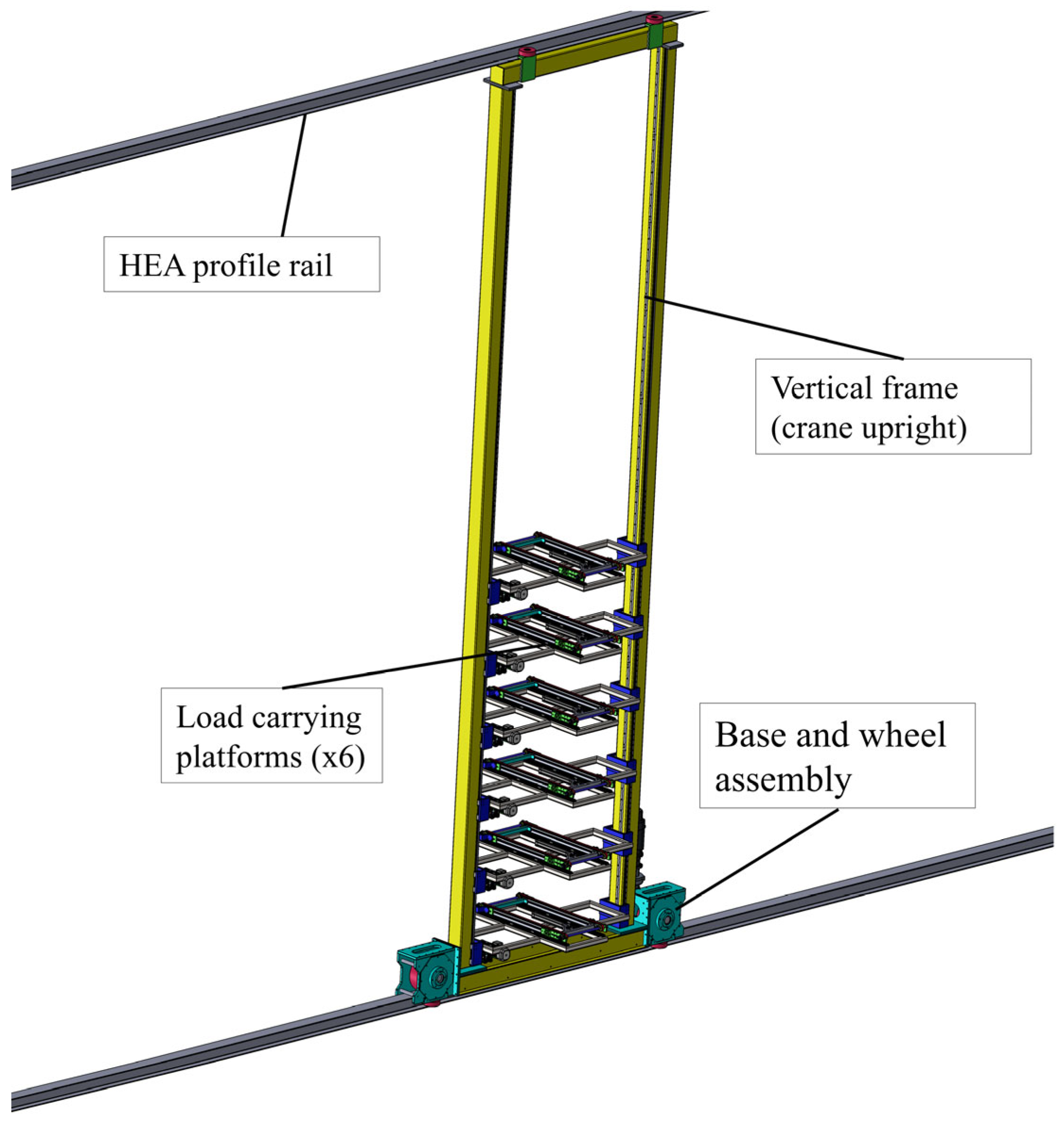
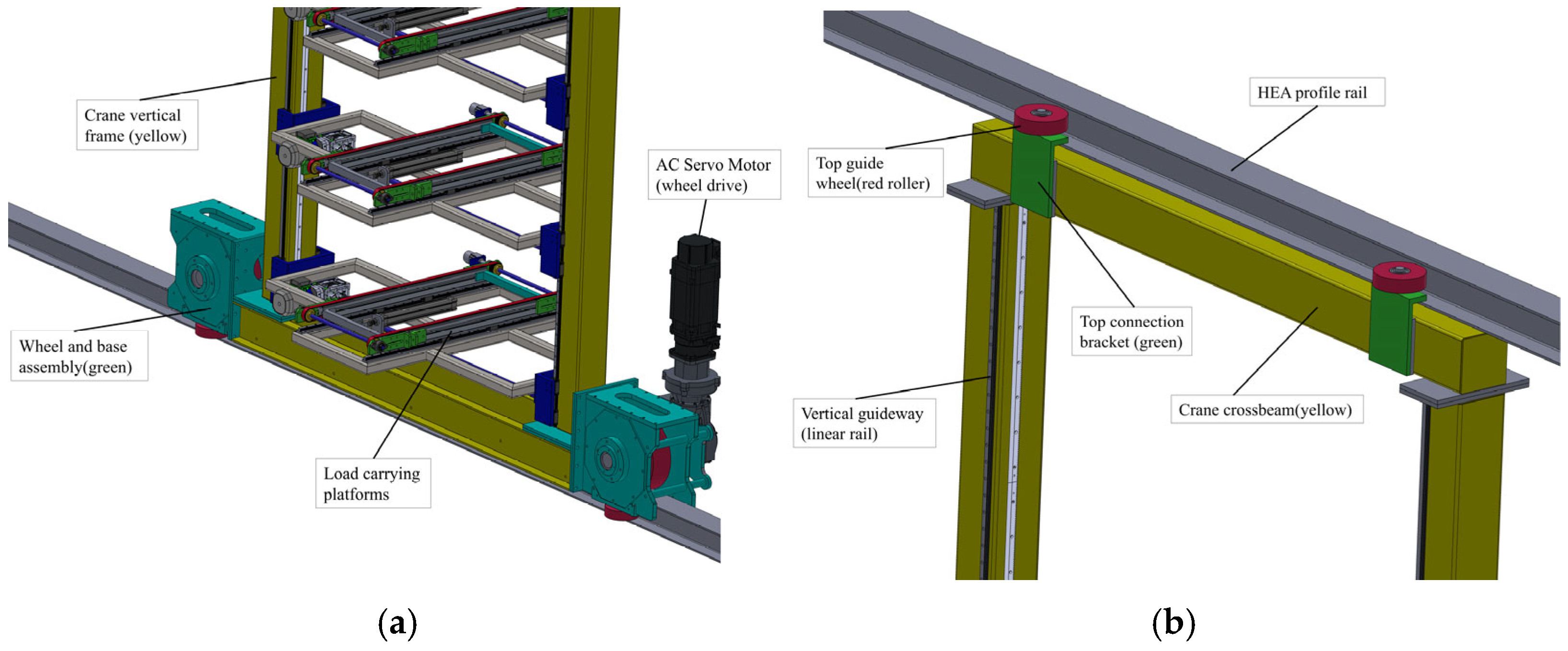
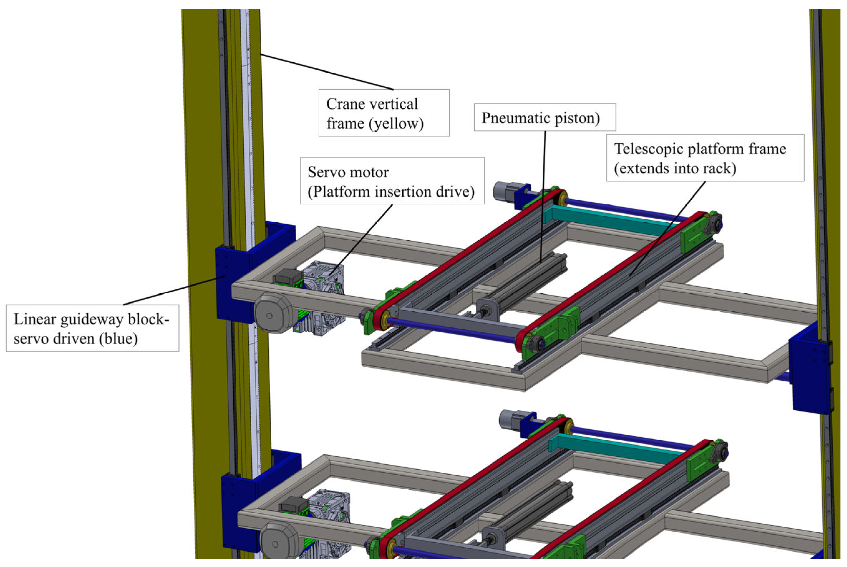
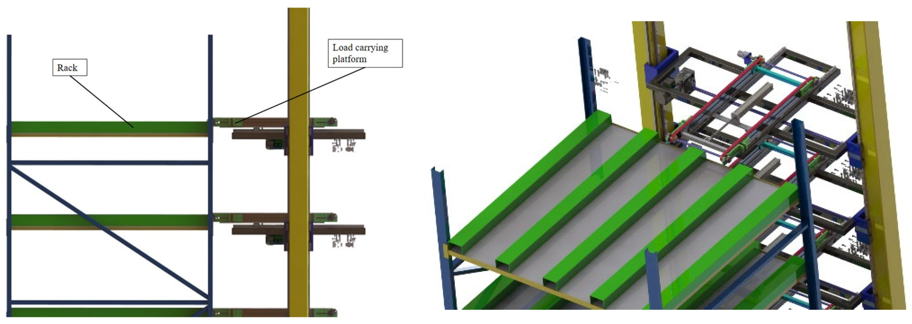
2]. Improving the operational efficiency of AS/RSs primarily depends on reducing the crane travel time. In conventional systems, the crane typically transports a single unit load from the production area to the storage rack. In high-throughput production environments, this sequential handling strategy may lead to congestion and temporary interruptions in material flow. To mitigate these limitations, enabling the crane to transport multiple loads within a single travel cycle emerges as an effective design approach. Accordingly, this study proposes a novel AS/RS crane architecture capable of carrying six unit loads simultaneously. The crane collects multiple products from a high-speed production line and transports them along the aisle for storage, thereby allowing multiple items to be stocked within a single travel period.
Fittinghoff et al. monitored the performance of a multi-level automatic storage and retrieval system for paper rolls under different operating conditions [
3]. Chen et al. conducted a study on the product retrieval planning of independently operating freight platforms of a crane with two load-carrying platforms [
4]. Polten et al., working on increasing efficiency by carrying multiple unit loads, developed a formulation for the routing problem to determine the storage route of the crane [
5]. Working on another multi-unit load-bearing AS/RS, Azzi et al. used a standard established by the Federation Européenne de la Manutention (F.E.M.) to estimate the travel time of a multi-unit crane [
6]. In another study conducted in this area, Wang Y., who addressed the scheduling problem for the retrieval task in the Multi-Deck Shuttle Storage System, developed a mixed-integer programming model [
7].
Working on increasing the efficiency of the system by minimizing the crane travel times, Lerher et al. presented analytical travel time models for single-aisle AS/RSs, taking into account features such as the acceleration, deceleration, and maximum speed [
8]. Liu et al. examined travel times for a crane design with a separate horizontal and vertical movement, instead of the horizontal and vertical cranes found in traditional AS/RSs [
9]. Modeling the travel time of one crane for storage and retrieval, Ghomri et al. developed a mathematical model based on the dimensions, product variety, and aspect ratio of the AS/RS rack [
10]. Kouloughli et al. optimized the system dimensions using numerical simulation to minimize the single cycle time in AS/RSs with sliding shelves [
11].
Several studies have addressed routing and scheduling optimization in AS/RSs, including operation sequencing in robotic compact storage systems [
12], ant colony optimization [
13], modular rack configurations [
14], genetic algorithms [
15], mixed-integer programming and integrated scheduling models [
16,
17], energy efficiency and storage assignment strategies [
18,
19], real-time transaction scheduling in multi-depth shuttle-based systems [
20], system performance monitoring [
21], crane scheduling [
22], efficiency improvements through increased transport capacity [
23], reliability analysis using fault tree and FMEA methods [
24], and small-scale automated storage organizer designs for retail environments [
25].
The majority of studies in the literature on AS/RSs focus on mechanical design, travel time analysis, and steering problems. However, studies addressing the issue of precise position control under variable load conditions in multi-carrier and independent drive systems of AS/RS crane structures are limited. In particular, comprehensive studies comparing adaptive PID-based control approaches optimized with different heuristic algorithms remain scarce in the literature.
Existing multi-load crane studies, such as Polten et al. [
5], transport two loads on a shared platform, requiring loads to be placed on adjacent rack positions. Dual-shuttle systems (Azzi et al. [
6]) increase the throughput through aisle-level parallelism but do not address the independent vertical positioning of multiple load units within a single crane. In contrast, the proposed design features six independently motorized vertical platforms, each capable of accessing any rack position regardless of the others. In addition to the mechanical and operational analysis, the position control problem of such systems under variable load conditions has not been sufficiently addressed. In this study, a novel autonomous AS/RS crane architecture with six vertically aligned and independently operated load platforms is proposed. Furthermore, the vertical position control of a single platform is investigated using a classical PID controller and an MRAC-based adaptive PID controller. The adaptation gains of the MRAC-PID controller are optimized using GA, SA, and PSO techniques. The performance of the proposed control strategies is evaluated through comparative simulations in terms of tracking accuracy, settling time, and robustness against external disturbances.
The present study establishes a theoretical and simulation-based framework for the proposed multi-platform AS/RS crane system. While a physical prototype implementation is beyond the scope of this work, the simulation environment is designed to mirror real operational conditions as closely as possible, providing a validated foundation for future experimental studies.
2. Purpose of Study
The primary objective of this study is to increase storage efficiency through a design that enables the transport of multiple load units during a single crane cycle. A crane design capable of transporting six-unit loads within a single travel cycle is proposed; the Turkish Patent and Trademark Office issued a Decision on Grant of Patent for this design on 21 April 2026 under Application No. 2023/018753 [
26]. Considering that traditional AS/RS cranes can carry one or two load units, the designed structure offers a simultaneous multi-load carrying capability. The proposed design reduces crane travel times to support high-capacity and efficient operation in AS/RSs with high investment costs.
Another objective of this study is to examine the vertical position control of one of the load-carrying platforms in the proposed multi-platform AS/RS crane structure. In this context, a classical PID controller and an MRAC-based adaptive PID controller were designed and compared for the platform’s position control. Furthermore, the adaptation gains of the MRAC-PID controller were determined using GA, SA, and PSO algorithms, and the effects of different optimization methods on the control performance were analyzed.
It is acknowledged that the six-platform crane architecture requires a building height approximately 1.5–2 times that of the storage racks, which exceeds the standard hall height of conventional warehouses. However, this requirement is consistent with the target application environment of the proposed system: newly constructed, high-throughput production facilities (greenfield projects) in sectors such as automotive assembly, electronics manufacturing, and heavy industry, where tall building structures are standard practice and the economic justification for the increased construction height is provided by the throughput gains demonstrated in this study.
4. Control System Design
4.1. Control Problem Definition
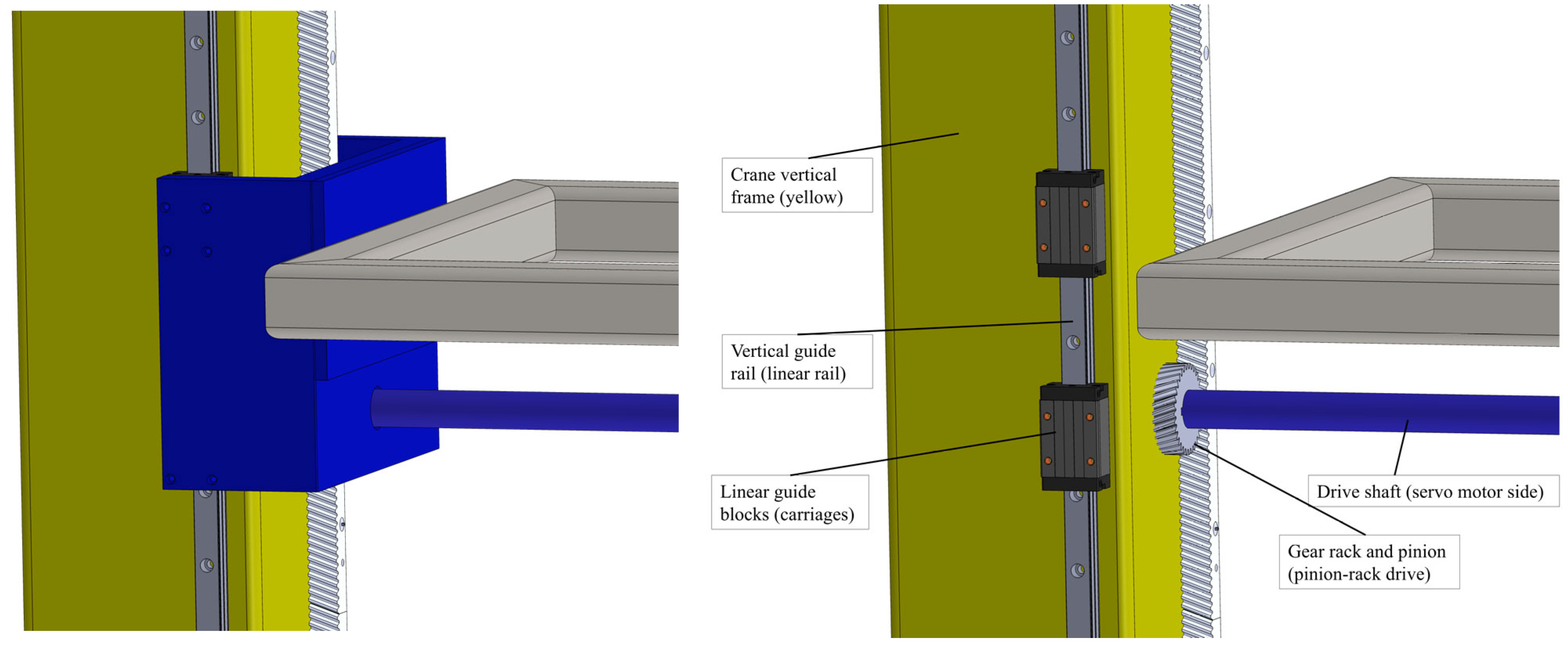
In the proposed multi-platform AS/RS crane structure, each load-carrying platform is driven independently in the vertical direction. In this study, only one of the six load-carrying platforms is considered, and the vertical position control of the platform is examined. The mass of the loads carried on the platform varies during operation, causing time-varying system dynamics and making accurate reference tracking a critical control problem for safe and efficient operation. Therefore, the need arises to use adaptive control approaches that can adapt to time-varying system dynamics. The analysis focuses on a single platform for several well-founded reasons: (i) Each platform is driven by an independent servo motor and pinion–rack mechanism with no mechanical linkage to adjacent platforms, making inter-platform coupling negligible by design. (ii) The servo drive bandwidth (typically > 100 Hz) is at least one order of magnitude higher than the platform motion bandwidth (<5 Hz), so actuator dynamics can be absorbed into the force constant Kf without loss of generality. (iii) Gear backlash introduces a small dead zone that is compensated by the position encoder feedback in closed-loop operation and is therefore treated as a bounded disturbance within the model uncertainty. (iv) Nonlinear friction and sensor delay represent second-order effects relative to the dominant load-mass variation (200–280 kg) and are left for future experimental refinement. The single-platform model thus captures the primary control challenge, variable load mass, while keeping the simulation framework tractable.
The control objective is formally defined as the regulation of the platform position x(t) to a desired reference trajectory xref(t) under time-varying mass m(t) ∈ [200, 280] kg, while maintaining bounded tracking error e(t) = x(t) — xref(t) for all admissible load conditions.
All control algorithms (classical PID and MRAC-PID) are implemented in discrete-time form within the MATLAB/Simulink R2025b (MathWorks Inc., Natick, MA, USA) environment, consistent with the digital implementation on a servo drive controller; a fixed sample time of Ts = 0.001 s was used for all simulations.
4.2. Dynamic Model of the Vertical Platform
An AC servo motor, gearbox, and pinion mechanism generate the vertical movement of the load-carrying platform. The rotational motion produced by the motor is converted into linear motion via the gearbox and pinion system. The platform, together with the load it carries, is modeled as a single equivalent mass.
The dynamic behavior of the platform in the vertical direction can be expressed using Newton’s second law as follows:
Here, m is the total mass of the platform and the load being carried, b is the viscous friction coefficient, (t) is the vertical position of the platform, Fm(t) is the linear force generated by the motor–pinion mechanism, and g is the gravitational acceleration. Since the platform moves along a vertical guideway, the gravitational term mg in Equation (1) acts as a constant load independent of the direction of motion; only its sign relative to the direction of Fm(t) changes between ascending and descending movements. Similarly, the viscous friction term opposes the platform velocity and therefore reverses sign with the direction of motion. Both effects are represented within the same dynamic model and applied as external disturbance inputs in the Simulink implementation, allowing a single-model structure to capture both the ascending and descending operation without requiring separate equations of motion. The structural stiffness term k·x(t) is omitted from Equation (1) because the pinion–rack mechanism transmits motion through rigid metallic contact; the effective stiffness of the drive train is several orders of magnitude higher than the inertial and damping forces acting at the motion frequencies of interest (<5 Hz), making its inclusion negligible for control design purposes.
4.3. Transfer Function of the Vertical Motion
This section derives the transfer function of the vertical motion of a single load-carrying platform, where gravity is treated as an external disturbance applied in the Simulink environment.
Considering the motor torque constant, gearbox ratio, and transmission elements, the linear force acting on the platform is proportional to the motor current and can be expressed as follows:
Here,
represents the motor current, and
Kf is the equivalent force constant [
27]. Considering the system parameters used in this study, the equivalent force constant
Kf = 222.222 was calculated.
When this expression is substituted into the equation of motion, and the Laplace transform is taken under zero initial conditions, the transfer function between platform position and motor current is obtained as follows:
In Equation (3), s denotes the complex Laplace variable, X(s) is the Laplace transform of the platform position x(t), and I(s) is the Laplace transform of the motor current i(t). The transfer function G(s) is obtained by substituting the motor force expression in Equation (2) into the equation of motion in Equation (1), and applying the Laplace transform under zero initial conditions. The mass m and friction coefficient b appear as parameters within G(s) rather than as independent arguments; accordingly, the transfer function is denoted G(s) = X(s)/I(s).
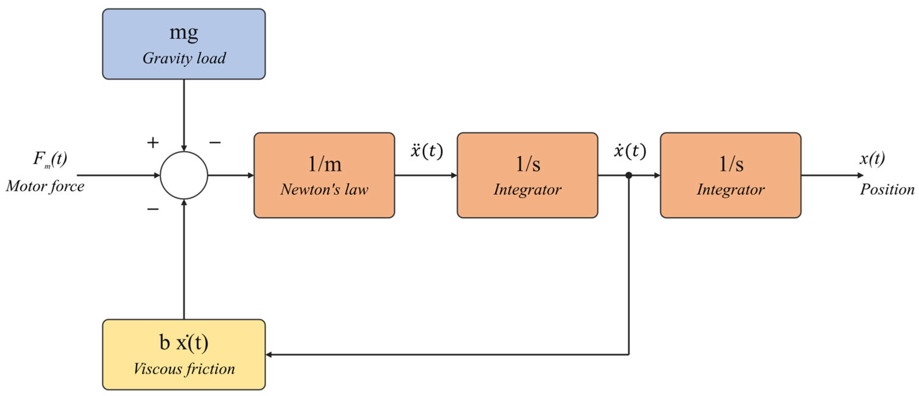
The controlled plant block diagram is shown in
Figure 7. The diagram includes the following: (i) the motor force input
Fm(
t) as the actuating signal; (ii) the gravitational disturbance term
mg acting as a constant load opposing upward motion and assisting downward motion; (iii) the nonlinear viscous friction term
b·ẋ(
t) opposing platform velocity; (iv) the platform mass
m as the inertial element; and (v) the position output
x(
t). The gravitational and friction terms are represented as additive disturbance inputs to the plant, consistent with the external disturbance formulation used in the Simulink implementation.
The K
f in the numerator of the transfer function represents the equivalent linear force coefficient obtained by considering the motor torque constant, gear ratio, and pinion mechanism. This coefficient expresses the relationship between the motor current and the linear force acting on the load-carrying platform. The proposed travel time model is based on simplified kinematic assumptions and does not account for all real-world operational constraints. The system parameters used in the dynamic model are given in
Table 1.
The resulting transfer function represents a position control system dependent on the mass parameter. Due to the variability of the transported load during operation, the system dynamics involve parameter uncertainty. Therefore, MRAC-based adaptive PID control structures are discussed in the following sections of this study.
4.4. Classical PID Controller Design
In this study, the position control of a single vertical load-carrying platform belonging to the proposed AS/RS crane system was primarily implemented using a classical PID controller. The classical PID controller, frequently used in industrial applications, generates the control signal based on the position tracking error [
28].
PID gains were determined using the Ziegler–Nichols method, which was selected as the reference tuning method due to its practical applicability. However, the variation in the total mass of the load-carrying platform during operation leads to uncertainties in the system dynamics and causes the performance of the constant-gain PID controller to decrease under different load conditions. Therefore, the classical PID controller was used as a comparison reference in this study; the results obtained under variable load conditions were compared with the performance of adaptive PID control structures. All simulations were performed under the same reference signal and the same disturbance factors [
29].
In this simulation-based study, the Ziegler–Nichols tuning values were obtained analytically from the linearized plant transfer function G(s) in Equation (3), without physical prototype experiments. Specifically, the ultimate gain Ku and ultimate period Tu were derived from the analytical frequency response of G(s) under proportional control, and the standard Ziegler–Nichols closed-loop formulae were applied to obtain Kp = 0.007333, Ki = 0.000194, and Kd = 0.069238. These values serve as the baseline reference for a comparison with the adaptive MRAC-PID controller.
4.5. MRAC-Based Adaptive PID Controller
In this study, an MRAC-based PID control structure was designed to overcome the performance limitations of the classical PID controller under variable load conditions. The main goal of the MRAC approach is to ensure that the output of the controlled system follows the output of a predefined reference model. In the MRAC-PID structure, the classical PID controller structure is preserved; however, instead of keeping the controller gains (
Kp,
Ki, and
Kd) constant, they are adjusted online through an adaptation mechanism. Thus, the aim is to reduce the adverse effects of uncertainties in the system dynamics on the control performance when the mass acting on the load-carrying platform changes during operation [
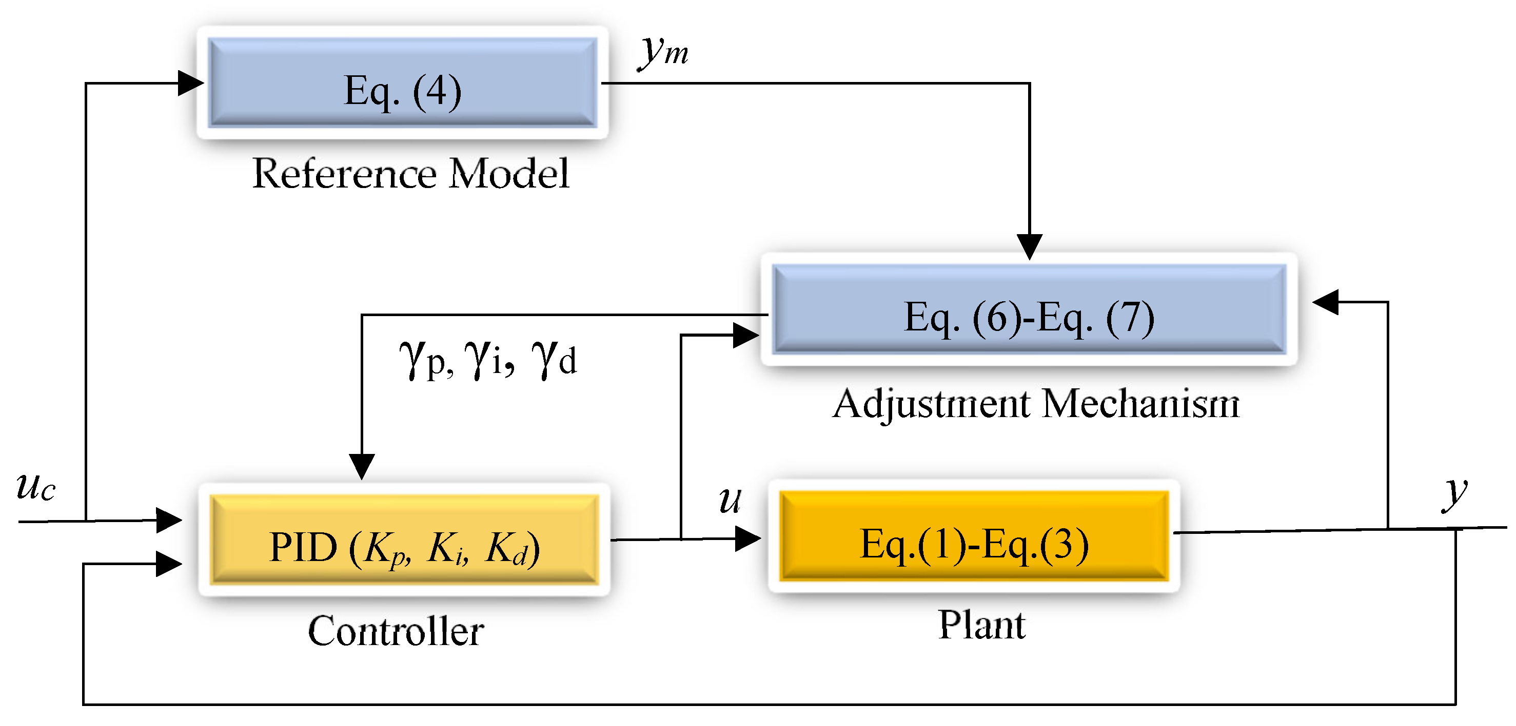
30]. The adaptive PID control model is shown in
Figure 8.
uc represents the reference input,
u the control signal,
yₘ the reference model output,
y the actual output, and
γp,
γi, and
γd the adaptation parameters. The reference model was chosen as a second-order system to represent the desired closed-loop dynamics. The reference model transfer function used in this study is as follows:
Note that Equation (4) defines the reference model, the desired closed-loop response that the plant output should follow, and is not a physical model of the platform. It therefore does not contain the plant parameters m and b; instead, its coefficients are chosen to specify the desired second-order dynamics (natural frequency and damping ratio). The reference model parameters were selected based on the physical constraints of the vertical platform drive system. The reference model dynamics were selected in accordance with the dominant inertial behavior of the plant under maximum load: with m = 280 kg and the linearized motor-position gain Kf/b ≈ 1, the open-loop plant behaves as a double integrator whose characteristic time constant is approximately ≈ 16.7 s, reflecting the sluggish inertial dynamics of the loaded platform. The selected second-order standard reference model, Gm(s) = 1/(s2 + 1.2s + 1), is characterized by a natural frequency of ωn = 1 rad/s and a damping ratio of ζ = 0.6. Given the sluggish dynamics of the system, the choice of ωn = 1 rad/s (corresponding to a reference settling time of 6.67 s) constrains the MRAC mechanism to a physically realizable velocity profile that is compatible with the actual mechanical bandwidth of the system, thereby preventing the actuator saturation that would occur with a faster reference model. The damping ratio of ζ = 0.6 yields a maximum overshoot of approximately 9.48%, which is acceptable for this application: AS/RS platforms operate with position tolerances of ±2 mm at the target rack face, and a transient overshoot of 9.48% on a 1 mm step command corresponds to a peak excursion of only 0.095 mm, well within the mechanical clearance between the platform and the rack structure. A settling time of 6.67 s is likewise consistent with the low-speed loading/unloading cycle of the system, which is designed to protect fragile goods, thereby avoiding mechanical fatigue while guaranteeing an optimal system response within hardware limits. This reference model is defined to provide fast transient behavior, low overshoot, and stable position tracking.
In the MRAC-PID control structure, an adaptation mechanism is established using the error signal between the system output
and the reference model output
. The error signal is formulated as follows:
The controller parameters are adapted online using the MIT adaptation law:
where γ is the adaptation gain and θ represents the adjustable controller parameters. The controller parameters are adapted online using the MIT adaptation law [
30], originally developed at the Massachusetts Institute of Technology for model reference adaptive control applications.
For the adaptive PID controller, the parameter
Kp,
Ki, and
Kd representing time-varying PID gains’ update laws are defined as follows:
These adaptation laws ensure that the controller parameters are continuously adjusted to minimize the tracking error.
The stability of the MRAC-PID structure is examined in the framework of the MIT rule. For the adaptation law in Equation (7) to guarantee bounded parameter adaptation, the adaptation gains
,
, and
must satisfy
< 2/‖∂y/∂θ‖
2, a condition verified for the gain ranges identified by GA, SA, and PSO in this study. The closed-loop stability under bounded disturbances and the parameter convergence behavior are further supported by the simulation results, where all controllers exhibit stable tracking without divergence across the tested load variations [
30].
The rate of change of these gains is determined by the adaptation gains (γ parameters), and the selection of these parameters directly affects the system performance [
30]. In this study, the MRAC-PID control structure was tested under the same operating conditions as a classical PID controller, and the position tracking performance was compared for different load conditions.
4.6. Optimization of Adaptation Gains
In the MRAC-PID control structure, the performance of the adaptation mechanism largely depends on the γ parameters. These parameters determine the rate of change of the PID controller gains and directly affect the convergence behavior of the system to the reference model. Poorly selected gamma values may result in sluggish adaptation or system instability.
In this study, heuristic optimization methods were used to determine the adaptation gains of the MRAC-PID controller. Three different methods were considered: GA, SA, and PSO. In the optimization process, the Integral of Time-weighted Absolute Error (ITAE), defined as J = ∫
0ᵀ t·|e(t)| dt where e(t) = y(t) − y
m(t), was used as the objective function. ITAE penalizes persistent errors more heavily than early transient errors, making it well-suited for position tracking problems where the settling accuracy is critical. To this end, performance metrics based on the error signal between the reference model output and the actual system output were used. The parameters used in those algorithms are given in
Table 2.
The selection of ITAE as the optimization criterion involves an inherent trade-off. While ITAE heavily penalizes persistent steady-state errors and late-phase deviations, it assigns a relatively low weight to early transient errors, which may allow large initial overshoots to go under-penalized during optimization. This is reflected in the SA-based results, where the optimizer converges to adaptation gains that produce an aggressive early adaptation (resulting in a 42.80% overshoot) but achieve a rapid steady-state convergence. In contrast, ISE would penalize large instantaneous errors more evenly, potentially reducing the overshoot at the expense of slower settling. ITAE was selected in this study because settling accuracy, rather than transient peak minimization, is the primary performance requirement for AS/RS position control, where the platform must reliably reach the target rack face position. The consequences of this choice are consistent with the observed results across all three optimization methods.
All simulations were conducted in a MATLAB/Simulink environment, and the parameters reported above were kept constant to ensure the reproducibility of the results. For all three algorithms, the search space for the adaptation gains was defined as γp, γi, γd ∈ [1, 50,000], based on preliminary simulations indicating that values outside this range either produced negligible adaptation effects or led to instability.
4.6.1. Genetic Algorithm
GAs are a heuristic optimization method inspired by the process of biological evolution and based on the principles of natural selection. In this algorithm, potential solutions are represented as chromosomes, and the fitness of each individual is evaluated using a defined fitness function. Better solutions are sought over generations using selection, crossover, and mutation operators. GAs are frequently preferred in control systems because they provide effective results in nonlinear, multivariate, and non-derivative optimization problems [
31]. In this study, GAs were used to optimize the adaptation gains in an MRAC-PID structure [
32]. The GA structure is given as pseudocode in
Appendix A (Algorithm A1).
4.6.2. Simulated Annealing Algorithm
Simulated Annealing (SA) is a probabilistic optimization algorithm inspired by the metallurgical annealing process. The algorithm starts with a high temperature, and explores the solution space to avoid local minima. By gradually reducing the temperature parameter, the solution is brought closer to a more stable minimum. SA is widely used for nonlinear optimization problems due to its ability to escape local minima and achieve near-optimal solutions [
33]. In this study, the SA algorithm was used to obtain values of adaptation gains’ near-optimal values [
34]. The SA structure is given as pseudocode in
Appendix A (Algorithm A2).
4.6.3. Particle Swarm Optimization
Particle Swarm Optimization (PSO) is a numerical optimization method inspired by the collective movement behavior of bird flocks and fish schools. In the algorithm, each particle updates its velocity and position in the solution space based on its own best experience and the overall best solution of the swarm. PSO is widely used in control and optimization problems due to its few parameters, fast convergence, and ease of implementation [
35,
36,
37]. The effectiveness of PSO-based tuning has also been demonstrated for nonlinear control problems; for example, Pham et al. [
37] applied PSO-optimized hierarchical sliding mode control to a rotary inverted pendulum, achieving a robust swing-up and stabilization performance. In this study, the PSO algorithm was used to determine the adaptation gains in an MRAC-PID control structure [
38]. The PSO structure is given as pseudocode in
Appendix A (Algorithm A3).
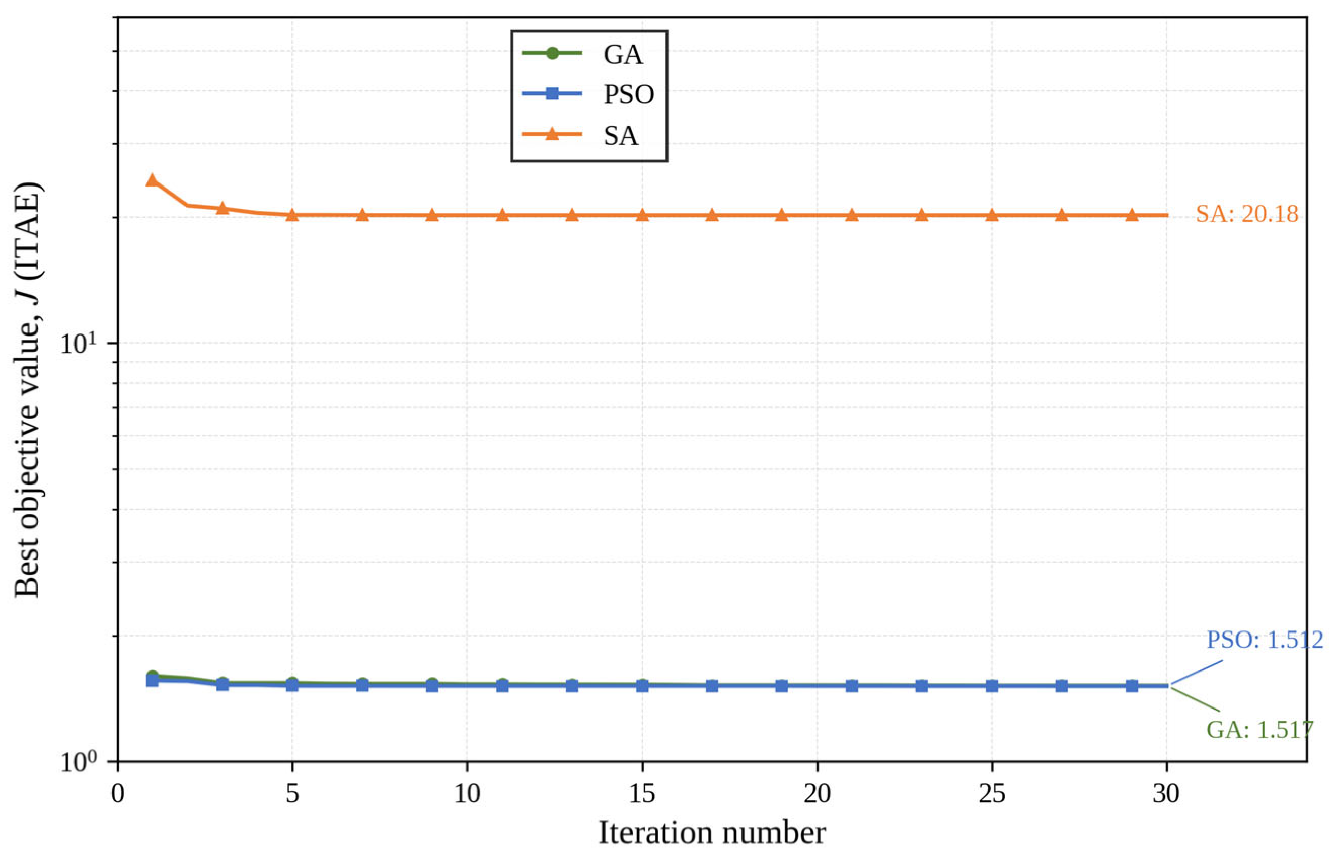
The convergence behavior of the three algorithms over 30 iterations is shown in
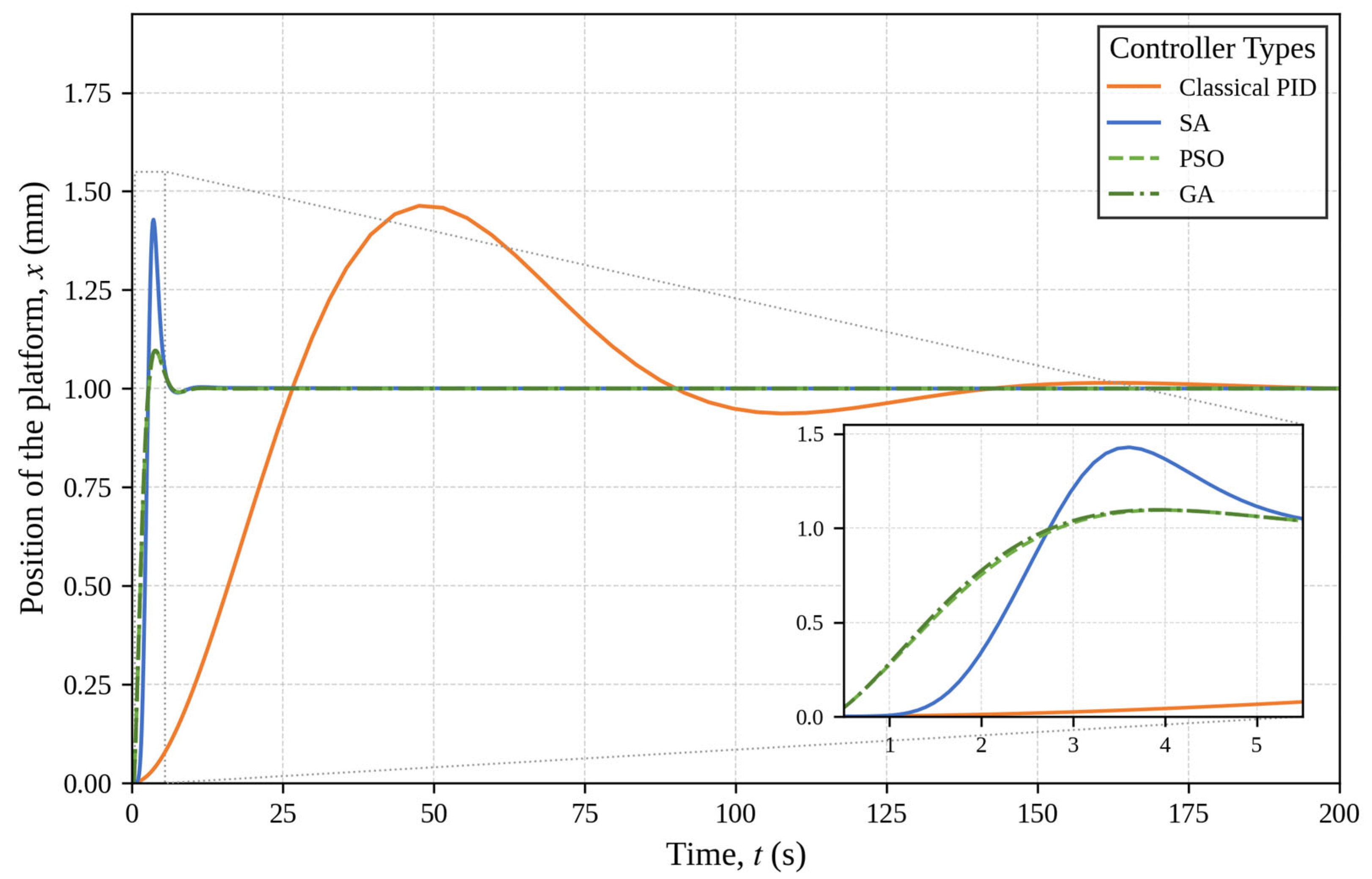
Figure 9. Both GA and PSO converge rapidly within the first five iterations to a similar objective value (J ≈ 1.51–1.52), consistent with the near-identical position responses observed in
Figure 9. The SA algorithm converges to a substantially higher objective value (J ≈ 20.18) and stagnates after approximately five iterations, reflecting its tendency to become trapped in a local minimum under the probabilistic acceptance criterion at lower temperatures. This is consistent with the higher overshoot exhibited by the SA-based MRAC-PID controller, as discussed in
Section 4.7. Each algorithm was executed once under identical initial conditions, disturbance profiles, and search bounds; a multi-run statistical comparison (mean and standard deviation over independent executions) is identified as a direction for future work.
4.7. Comparative Simulation Results
This section presents a comparative analysis of the position responses of a classical PID controller and an MRAC-PID controller obtained using different optimization methods. In this study, two different levels of comparison are performed. First, the performance of a classical PID controller tuned by the Ziegler–Nichols method is compared with the proposed MRAC-PID controller. Second, the effect of different metaheuristic algorithms (GA, PSO, and SA) on the adaptation gain (γ) of the MRAC mechanism is investigated.
It should be noted that the Ziegler–Nichols method is used as a baseline tuning approach due to its widespread use in industrial applications. However, its limitations for high-order systems are acknowledged, and, therefore, the comparison aims to demonstrate the adaptability advantage of the MRAC-PID rather than absolute optimality.
The simulation scenario consists of a unit step reference position command of
xref = 1 (normalized unit), applied at t = 0 under constant load conditions (
m = 200 kg and
m = 280 kg, separately). The normalized reference amplitude is used to facilitate a dimensionless comparison of controller performance; in the physical system, the actual platform displacement per storage cycle ranges from 0.5 m to 3.16 m depending on the target shelf position. The one-unit step therefore represents a normalized worst-case positioning command. All simulations were conducted with the same initial conditions (
x(0) = 0,
ẋ(0) = 0) and under identical disturbance profiles. A step reference signal was chosen to enable a rigorous evaluation of transient response characteristics (overshoot, rise time, and settling time) under the most demanding input condition. The use of a trapezoidal reference profile, which would reduce instantaneous acceleration demands, is a direction for future experimental implementation and is consistent with the Type-1 velocity profile adopted in the travel time model of
Section 5.
Unlike conventional studies where metaheuristic algorithms are used to tune PID gains directly, in this study, GA, PSO, and SA are employed to optimize the adaptation gain (γ) of the MRAC mechanism. This approach allows improving the dynamic adaptation capability of the controller rather than static gain tuning.
All simulations were performed under the same reference position signal, the same initial conditions, and the same disturbances. The position responses of the load-carrying platform are shown in
Figure 10. As shown in
Figure 10, the classic PID controller exhibits a significant overshoot and a long settling time. Using the MRAC-PID controller, significant improvements in the position tracking performance were achieved for all optimization methods. The responses obtained using adaptation gains determined by GA and PSO were almost identical. This indicates that both optimization methods can effectively determine the adaptive controller parameters and achieve similar performance levels. The SA-based controller exhibits a faster rise time but higher overshoot; however, it converges to a stable response. This behavior can be attributed to the probabilistic acceptance mechanism of the SA algorithm: at an elevated temperature, the optimizer may accept candidate solutions with large adaptation gains that produce a more aggressive response. Although this results in a higher initial overshoot, the settling time remains comparable to the GA- and PSO-based controllers, as the larger adaptation gains also accelerate error correction once the transient subsides. As shown in
Table 3, the ITAE values reflect this trade-off more clearly than settling time alone, since ITAE penalizes the prolonged transient associated with the overshoot.
In a physical implementation, the rapid adaptation transient exhibited by the SA-based controller (42.80% overshoot at t ≈ 3.6 s) would correspond to a momentary position overshoot of less than 0.43 mm on a 1 mm reference command, a value within the mechanical clearance envelope of the platform–rack interface (±2 mm). However, the associated acceleration peak would need to be verified against the servo drive current limits and mechanical joint tolerances in a hardware prototype.
The transient response parameters of the classical PID and the MRAC-PID controllers (PSO, SA, GA) are compared in
Table 4, including rise time, peak time, overshoot, settling time, and steady-state error.
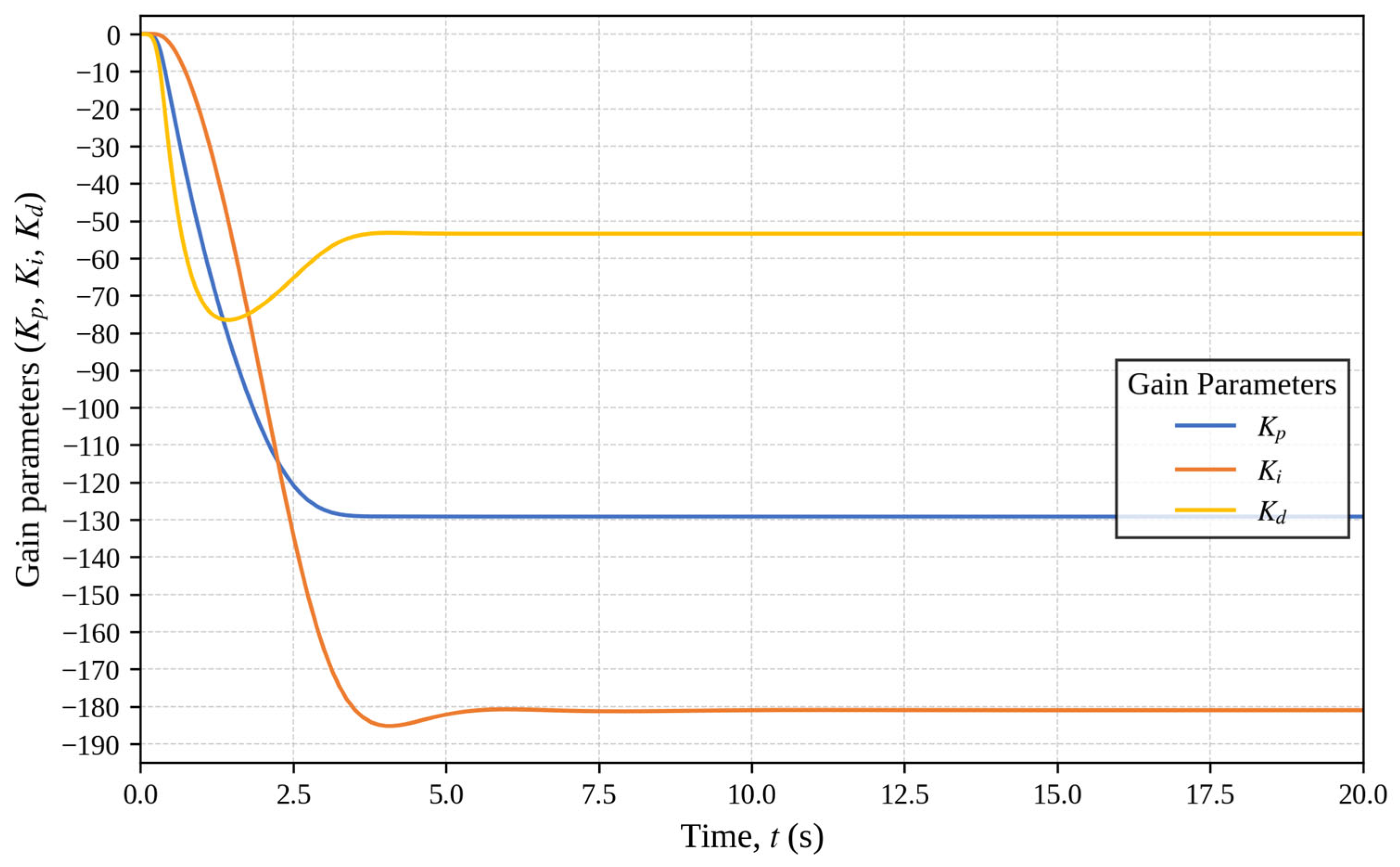
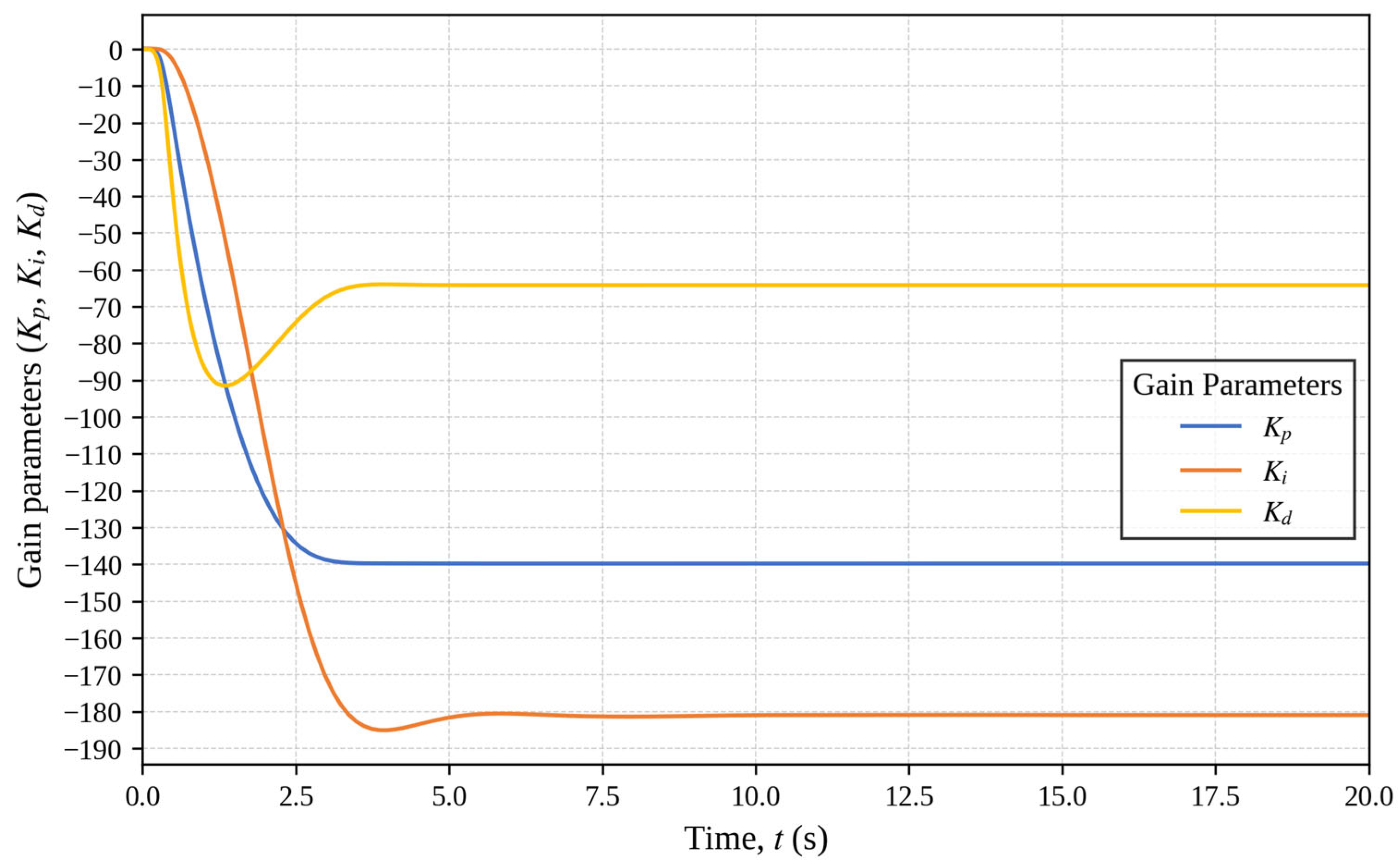
The platform weight is 200 kg when empty and 280 kg under maximum load. The changes in the adaptive PID gains (
Kp,
Ki, and
Kd) for these two conditions are shown in
Figure 11 and
Figure 12, respectively.
Overall, it is clear that the MRAC-PID control structure provides faster, more stable, and lower overshoot position control in AS/RS crane systems with variable load conditions compared to the classical PID controller. Furthermore, determining the adaptation gains using heuristic optimization algorithms has significantly improved the adaptive controller performance.
In addition to the position tracking error, the control signal u(t) (motor current command) generated by each controller was examined to verify the physical feasibility. For all evaluated controllers, the peak control signal remained within the representative rated current limit of Imax = 8 A, which corresponds to the nominal current rating of a typical 1–3 kW AC servo drive suitable for driving a pinion–rack mechanism with a 200–280 kg payload capacity. It is acknowledged that the precise current limit would depend on the specific drive hardware selected in a physical implementation; this value is used here as a representative upper bound consistent with the simulation scenario.
The initial values of the adaptive gains (
Kp,
Ki, and
Kd) shown in
Figure 11 and
Figure 12 correspond to the gains obtained from the Ziegler–Nichols tuning in
Section 4.4, which serve as the initial condition for the MIT adaptation law in Equation (7); the subsequent transient reflects the online convergence of these gains toward their optimized steady-state values under the applied load condition.
5. Analytical Travel Time Model for Multi-Corridor AS/RS and Efficiency Analysis
This section derives the total travel time required to fill the warehouse for two crane configurations (single-platform and six-platform), using a triangular velocity profile. The derivation proceeds in three steps: (i) the travel time for a single point-to-point movement is expressed as a function of distance and acceleration (Equations (8)–(17)); (ii) this expression is applied to each shelf position to obtain the cumulative travel time for one crane and (iii) the results are aggregated across all five crane aisles to obtain the total warehouse filling time, which is then compared between the two configurations.
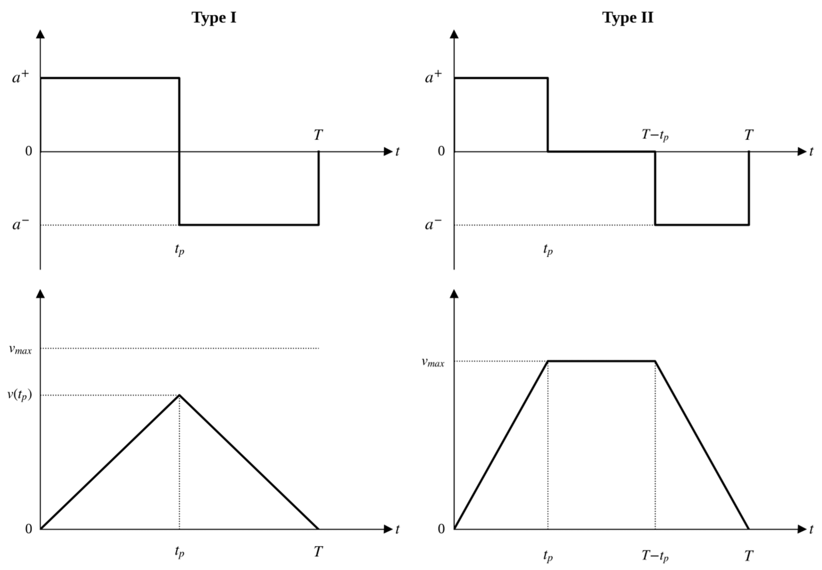
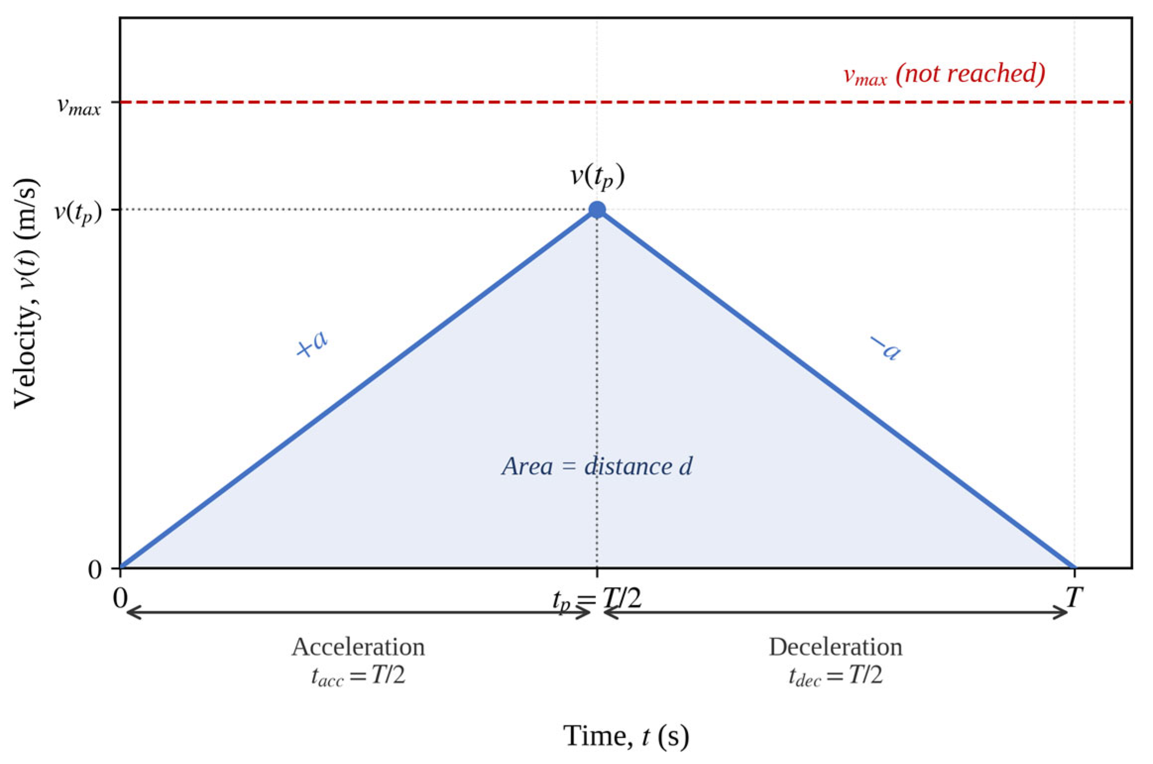
Two approaches can be used when modeling the travel time. These are the first approximation (Type 1) where the peak velocity of the crane (
v(
tp)) at any time
t is lower than the maximum velocity (
vmax) of the crane [
8]. In this case, the travel time
T and the acceleration–deceleration of the crane
a is as follows:
In the second type approach, the peak speed of the crane is equal to the maximum speed of the crane (Type 2). In this case, the travel time
T is as follows:
These velocity profiles are illustrated in
Figure 13.
In this case, for Type 1, the velocity based on time can be expressed as follows:
In this case, the distance (
T) can be expressed as the distance depending on time as follows:
Using Equation (12), the total distance traveled can be expressed by Equation (13):
If Equation (13) is solved, the equation in Equation (14) is formed for the total distance traveled:
Since the acceleration and deceleration of the crane are
and equal, the times to reach the peak velocity of the crane and 0 m/s are equal. Accordingly, the crane reaches the peak speed in half of the travel time and reaches 0 in half. In this case, the maximum speed of the crane will be half of the travel time.
If Equation (15) is used in Equation (14), Equation (16) is reached:
In this case, the travel time can be found as follows:
For type 2, the speed depending on time can be expressed as follows:
In the proposed AS/RS, the crane does not unload all six platforms at a single rack location; instead, within a single travel cycle, the crane stops at multiple rack positions along the aisle, unloading one or more platforms at each stop before proceeding to the next assigned position. As a result, the distance traveled between consecutive unloading positions is short, since these positions correspond to the nearest available storage slots rather than a single fixed destination. Consequently, individual platform travel distances are short and distributed across the aisle, remaining within the range where the platform does not reach its maximum velocity. Therefore, the Type-1 (triangular) velocity profile is adopted in the travel time analysis, as it accurately represents the actual motion regime of the system [
8]. Trapezoidal profiles, which assume sustained maximum velocity travel, are applicable to longer aisle configurations and fall outside the operational characteristics of the present design.
The time intervals of the Type-1 profile are detailed in
Figure 14, where the acceleration and deceleration phases (each equal to
T/
2), the peak velocity
v(
tp), and the unreached maximum velocity
vmax are marked. The area under the velocity profile corresponds to the distance traveled by the crane.
Using the Type 1 approach, the total travel time for the 1200-unit load storage, with analytical travel time
t1,
t2,
t3,
t4, and
t5, of the crane with a single load-carrying platform is given below:
The load handling time is assumed to be 2 s for comparison purposes. This value represents an idealized condition and may vary depending on the mechanical design and operational constraints. In this case, the load handling times are given in Equation (20):
There are 20 shelves side by side where each crane can store loads. The total travel time for the crane is the sum of the time the crane reaches the shelf and the loading time. Since the distances of all the cranes to the shelves are the same, the travel times are also the same. Since there are six units of load on each rack and each crane can feed two opposite racks, the following equation is obtained by multiplying each travel time by 12:
The travel times
for the crane with one load-carrying platform, determined using Equation (17), where
is the distance from the crane to the shelf,
is the loading time,
is the acceleration, and
i is the shelf number, are given in
Table 5. The travel times of the crane with one load-carrying platform are calculated using Equation (22) according to the values given in
Table 5.
In this case, the storage time for each crane to store 120-unit loads on 20 different racks is as follows:
Since the distances between each crane and the feeding zones are equal, the travel times t2, t3, t4, and t5 are equal to each other:
In Equation (25), the time to fill the 1200 unit-load warehouse is given for five cranes with a single load-carrying platform.
The analytical travel time model of the crane with six load-carrying platforms using the Type 1 approach is given below:
The loading time of six units of load for each crane is 12 s. In this situation,
The travel time is multiplied by 2, as the crane, which can carry six units of load, goes only once to each shelf and twice to the two opposite shelves.
The travel times
t1i for the crane with six load-carrying platform, determined using Equation (17), where d
k1 is the distance from the crane to the shelf, t
l1 is the loading time, a is the acceleration, and
i is the shelf number, are given in
Table 6. The travel times of the crane with six load-carrying platforms are calculated using Equation (29) according to the values given in
Table 6:
The total travel time is obtained by summing the travel times of five cranes:
Since the distance between the collection point and the storage point of each of its five cranes is equal, the travel times t
2, t
3, t
4, and t
5 are also equal;
In Equation (33), the time to fill the 1200-unit load warehouse is given for five cranes with six load-carrying platforms.
The travel time analysis presented in this study reveals the theoretical efficiency advantages of the proposed multi-platform AS/RS crane structure. However, the practical realization of these advantages depends particularly on the precise and stable position control of each load-carrying platform along the vertical axis. Therefore, in the following sections of the study, classical PID and MRAC-based adaptive PID control approaches for one load-carrying platform of the proposed crane structure are considered, and the control performance of the system under variable load conditions is examined in detail.
6. Discussion
In this study, a new crane design and AS/RS model are presented. The time required to fill a 240-unit storage area is compared for a traditional single load-carrying crane and a crane with six uniquely designed load-carrying platforms.
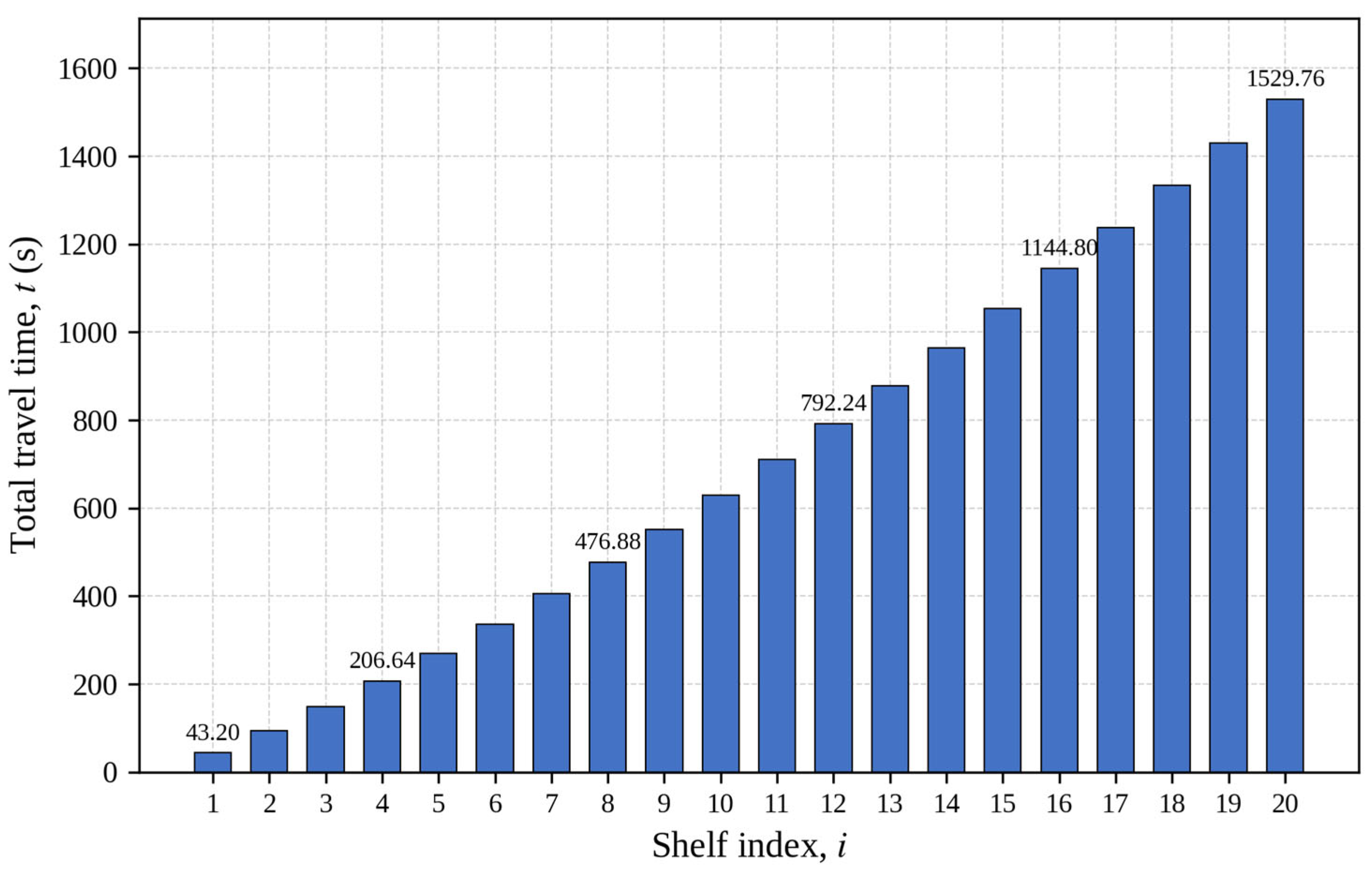
Table 5 shows the travel time required to load 240 units of load onto a crane with one load-carrying crane.
As illustrated in
Figure 15, since the storage distance changes after every 12 loads are stored, the travel time also changes in 12-load periods. A 1529.76 s travel time is needed to fill the 240-unit load storage area in a single transport platform crane.
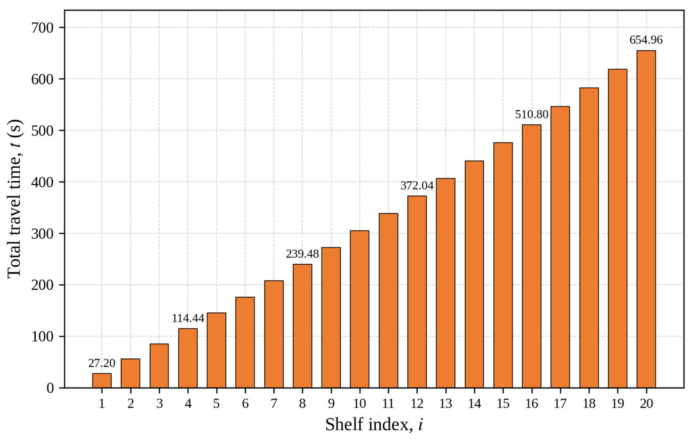
Table 6 shows the travel time required to fill the 240-unit storage area in the corridor where the crane with six transport platforms designed in this study moves.
The graph of the total travel times given in 12-unit load periods in
Table 6 is shown in
Figure 16. The crane travels each distance twice in order to take a total of 12 units of load on two opposite shelves.
According to
Figure 16, the crane with six load-carrying platforms takes 654.96 s to store 240 units of load.
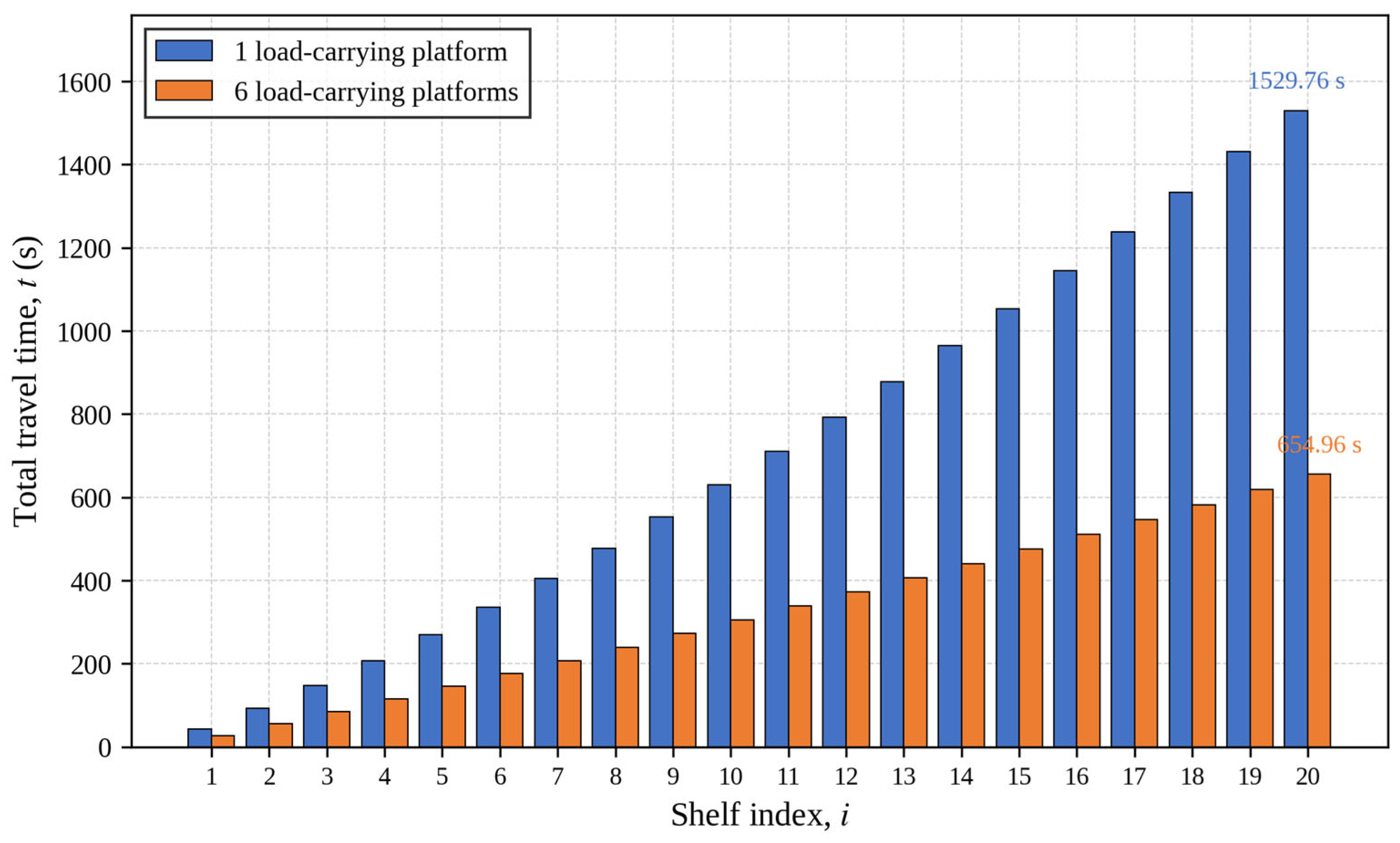
In
Figure 17, the travel time graphs of the cranes with a single and six load-carrying platforms are seen comparatively. As can be seen in the graph, the crane with six load-carrying platforms travels for 654.96 s for 240 units of load, while the crane with a single load-carrying platform travels for 1529.76 s. The designed system has a 58% less travel time than traditional methods. Although the obtained improvement appears significant, it should be interpreted as a theoretical upper bound rather than an exact real-world value.
According to the graph given in
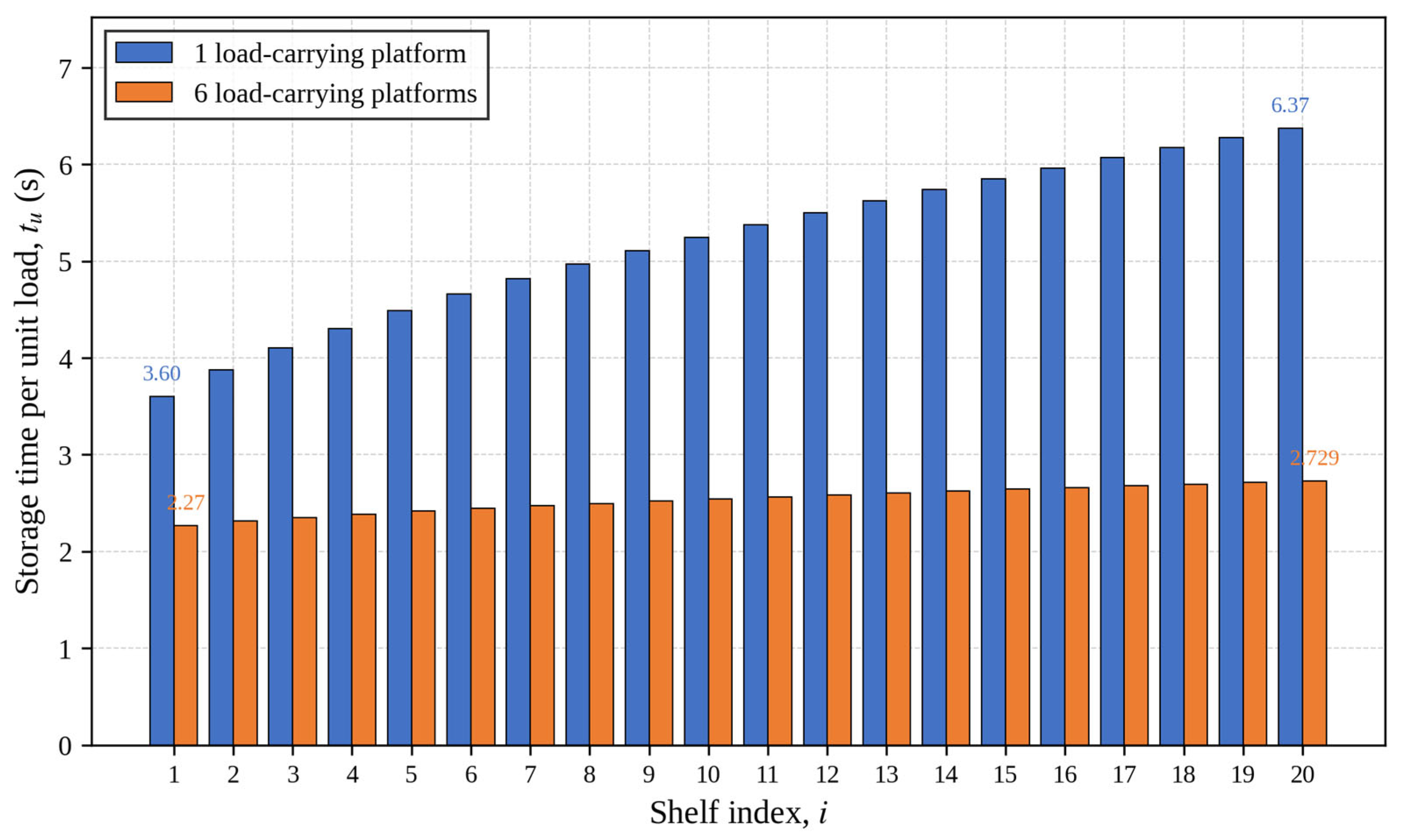
Figure 18 below, the carrying time of a unit load increases from 3.6 s for a crane with one load-carrying platform to 6.37 s for a 240-unit load, while it increases from 2.2 s to 2.729 s for a crane with six load-carrying platforms.
When the graph in
Figure 18 is examined, it is seen that, as the warehouse area grows, the storage capacity increases, the time of carrying a unit load of the crane with one load-carrying platform will increase more than the time of carrying a unit load of the crane with six load-carrying platforms, and the efficiency of the designed system will increase further.
The results of the travel time analysis indicate that the proposed multi-platform crane design has the potential to significantly improve the operational efficiency compared to conventional single-platform systems. By enabling the simultaneous transport of multiple load units, the system reduces idle movements and increases the throughput capacity.
However, this improvement is derived under simplified assumptions, and therefore should be interpreted as an idealized performance estimation. In real-world applications, factors such as acceleration limits, return travel times, and scheduling constraints may influence the achievable efficiency.
A review of the literature shows that, Polten et al. [
5] designed a crane capable of carrying two unit loads on a single platform. However, in that design, both loads must be placed on the same shelf. Consequently, retrieving one unit load requires retrieving the other to maintain storage efficiency. However, in the crane proposed in this study, the load-carrying platforms on the crane can access all rack locations and can place the desired load in the desired location. This system enables the warehouse areas to be used efficiently and without any congestion that may hinder production in high-throughput production environments.
In this study, both the mechanical design and the vertical-axis position control performance of the proposed multi-platform AS/RS crane were evaluated. The simulation results indicate that, while the classical PID controller provides an acceptable performance under nominal conditions, it exhibits significant degradation under varying load conditions and system parameter fluctuations. In contrast, the proposed MRAC-PID controller maintains a superior tracking performance and stability due to its robust adaptive structure. Furthermore, the integration of metaheuristic algorithms for tuning the adaptation gain significantly enhances the transient response characteristics and convergence speed. Among the evaluated methods, PSO and GA yielded more stable results and reduced the steady-state error compared to the slower adaptation observed with SA.
The integration of the proposed crane design with an adaptive control strategy is essential to fully realize the efficiency gains. While the 58% travel time reduction originates from the multi-platform mechanical architecture, its practical realization depends on the ability of each platform to reach its target position accurately within the allotted time window; a positioning error that requires re-homing would introduce additional travel time that partially offsets the structural advantage. The MRAC-PID controller, by maintaining the tracking accuracy under variable load conditions, is therefore a prerequisite for the full realization of the efficiency gain, not a separate contribution.
7. Conclusions
Using this model, the proposed six-platform crane system was compared with a traditional single-platform crane. The simulation results indicate up to a 58% reduction in travel time under the assumed operating conditions. This finding quantitatively demonstrates that multiple platforms significantly reduce the cycle time in AS/RSs.
In addition, the vertical motion of the crane was also analyzed from a control engineering perspective. It was observed that the adaptive control structure is more robust against changes in system parameters and disturbing effects, and follows the reference model more successfully.
In conclusion, this study proposes an effective solution for improving the efficiency and flexibility of high-investment AS/RSs by combining a novel crane design capable of carrying multiple loads simultaneously, an analytical travel time model, and an adaptive control approach. The findings clearly demonstrate the feasibility of the proposed system and its operational advantages, particularly in industrial facilities where mass production takes place and high-volume storage is required.
Future work will focus on the experimental validation of the proposed design through hardware-in-the-loop (HIL) testing and physical prototype implementation. The simulation results presented herein provide the necessary theoretical groundwork and parameter baseline to guide such experimental efforts, reducing both cost and risk in the prototyping phase.