1. Introduction
Plunge milling is a high-efficiency metal cutting process characterized by low radial cutting forces, excellent cutting stability, and the ability to utilize tools with large aspect ratios. These features make it particularly well-suited for roughing deep cavities and grooves [
1,
2]. In recent years, researchers have increasingly explored the application of plunge milling to the machining of integral impellers [
3,
4,
5]. During operation, the impeller is subjected to high stress levels in its outer region, with the stress in the shroud being higher than that in the hub. Consequently, stress concentration tends to occur at the blade root. To avoid this, the blade root must be properly filleted, as the machining quality of this region significantly affects the aerodynamic performance of the component.
Tool path planning is essential for machining the blade-root fillet region. Currently, this region is typically machined using ball-end cutters in a process known as cleaning root machining. Several researchers have explored different methods and techniques to optimize tool paths for efficient and accurate machining. Gian [
6] conducted a study to assess the viability of utilizing open regions and vector fields to determine the appropriate tool orientation in five-axis NC machining of cavity regions with undercut areas. They successfully implemented this approach to machine a specific type of impeller. Gong [
7] proposed a novel method for generating tool paths in flank milling while considering constraints for ball-end cutters. This method takes into account various constraints to optimize the tool path generation process. Ren [
8] introduced a technique that utilizes a series of intermediate virtual cutters to identify clean-up boundaries and construct clean-up tool paths. This method can be seamlessly integrated into CAD/CAM systems to automatically detect clean-up regions in polyhedral models and generate corresponding tool paths. Zhu [
9] presented an innovative approach for five-axis pencil-cut machining planning using a 5-DOF (degree of freedom) output haptic interface. They further demonstrated the practical implementation of the haptic pencil-cut system through relevant examples. Tang [
10] presented an efficient and robust tool path generation method that utilizes a ball-end cutter with a radius smaller than the design radius of the clean-up region. This approach allows for rapid planning of clean-up tool paths and results in excellent surface finish quality. Luo [
11] proposed a novel clean-up tool path generation approach for multi-patch solid models. The method relies on a theoretical model of the solid model, eliminating the need for STL forms and offset surfaces. This simplifies and accelerates the calculation process, significantly enhancing the level of automated programming. Feng [
12] put forward an innovative clean-up tool path planning method based on the cutter center point of the fillet boundary. The primary goal is to minimize excess residual material during machining. Moreover, this method can devise clean-up tool paths based on the cutter center point’s position, even in scenarios where data for combinatorial surfaces might be missing.
Recent international studies have further advanced impeller machining and five-axis tool-path planning from several perspectives. Digital-twin-based methods have been applied to impeller geometric optimization, machining-error prediction, and process optimization [
13,
14]. High-efficiency impeller machining strategies, including five-axis U-pass milling, double-row slotting plunge milling, SIRD-aware tool-path optimization, and transitional tool-path planning for large-diameter tool replacement, have also been reported [
15,
16,
17,
18]. These studies confirm the increasing relevance of plunge milling and advanced tool-path planning in integral impeller machining. However, their main focus is on global runner machining, machining-error control, cutting-load regulation, SIRD suppression, or residual material reduction, rather than on local overcutting avoidance at the blade-root fillet.
For the blade-root or blade-hub fillet region, existing studies have mainly focused on clean-up finishing or fillet radius design. Feng [
12] proposed a clean-up tool-path generation method for combinatorial surfaces based on the cutter center point of the fillet boundary, and Vavruska [
19] investigated impeller blade fillet radius determination for productive finish milling. These studies demonstrate the manufacturing importance of the blade-root fillet. Nevertheless, clean-up methods are mainly oriented toward ball-end or fillet-end finishing operations, whereas plunge milling generally uses flat-end cutters. Since cutter position and tool orientation are strongly coupled for flat-end cutters [
20], local interference avoidance in flat-end plunge milling is different from conventional ball-end clean-up machining. Therefore, automated local overcutting detection and correction for blade-root fillets in five-axis plunge milling remain insufficiently studied.
Currently, global verification methods, such as solid-model Boolean simulation, voxel representation, and signed-distance-field-based machining simulation, can be used to detect cutter-workpiece interference [
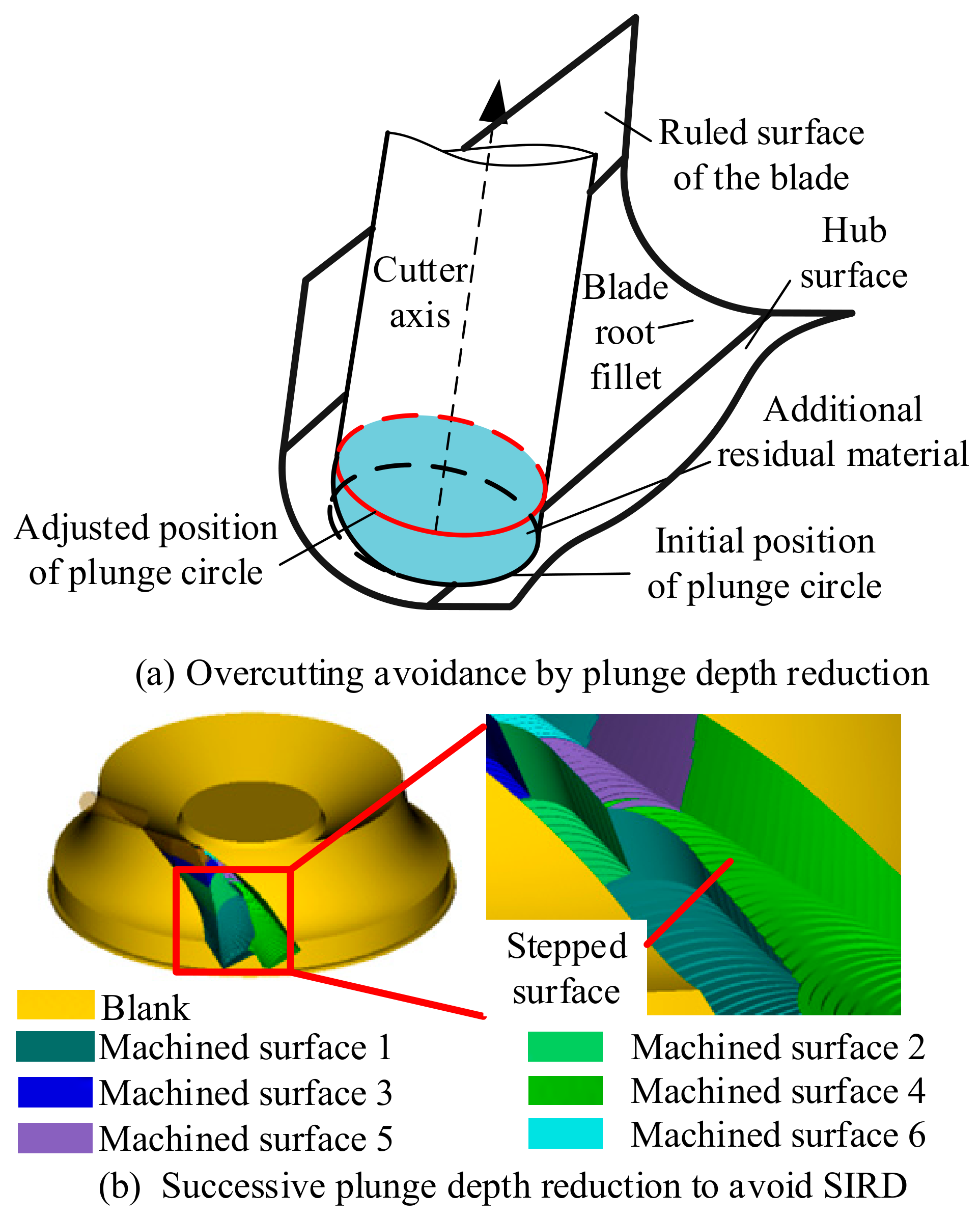
21]. However, these methods generally provide global or discretized machining-state information and do not directly extract the local overcutting depth and direction required for targeted tool-path correction. In practice, when overcutting is detected, the plunge depth is often reduced to avoid interference, as shown in
Figure 1a. However, if the plunge depth is reduced only at the cutter positions where overcutting occurs, subsequent plunge cuts must also be adjusted to avoid SIRD, as shown in
Figure 1b. This causes residual material on the hub surface to accumulate progressively and weakens the high-efficiency advantage of plunge milling.
To obtain local and actionable interference information, this study adopts a rolling-ball-based local modeling strategy for the blade-root fillet. The rationale is that engineering fillets are commonly generated as circular or sphere-envelope transition surfaces between adjacent functional surfaces. Compared with global solid-model Boolean operations, the rolling-ball model avoids repeated global subtraction and directly describes the local fillet geometry involved in overcutting. Compared with voxel or signed-distance-field representations, it retains parametric geometric information, making it easier to extract the interference direction and overcutting amount for subsequent tool-path adjustment. Compared with more flexible NURBS- or PDE-based blending models [
22], the rolling-ball model is simpler and more suitable for constant-radius or smoothly varying blade-root fillets commonly used in engineering design. Its limitation is that it is most suitable for regular circular or smoothly varying fillets; highly free-form, discontinuous, or non-standard transition regions may require additional fitting, segmentation, or hybrid modeling. Based on this model, this study develops a semi-analytical method to identify overcutting between a flat-end plunge cutter and the blade-root fillet, extract local interference information, and automatically modify the plunge milling tool path.
This paper presents a method to avoid overcutting at the blade-root fillet in plunge milling of integral impellers. The key features of this method are as follows:
- (1)
A semi-analytical model is established to identify overcutting between the plunge cutter and the blade-root fillet. This model enables rapid detection of cutter positions where overcutting occurs and extracts information about the overcut region, providing guidance for overcutting elimination.
- (2)
Compared with the conventional approach of reducing plunge depth to avoid overcutting, the proposed method achieves automated overcutting elimination. It significantly reduces the residual material volume, thereby fully leveraging the high efficiency of plunge milling.
2. Parameterized Model of Blade-Root Fillet
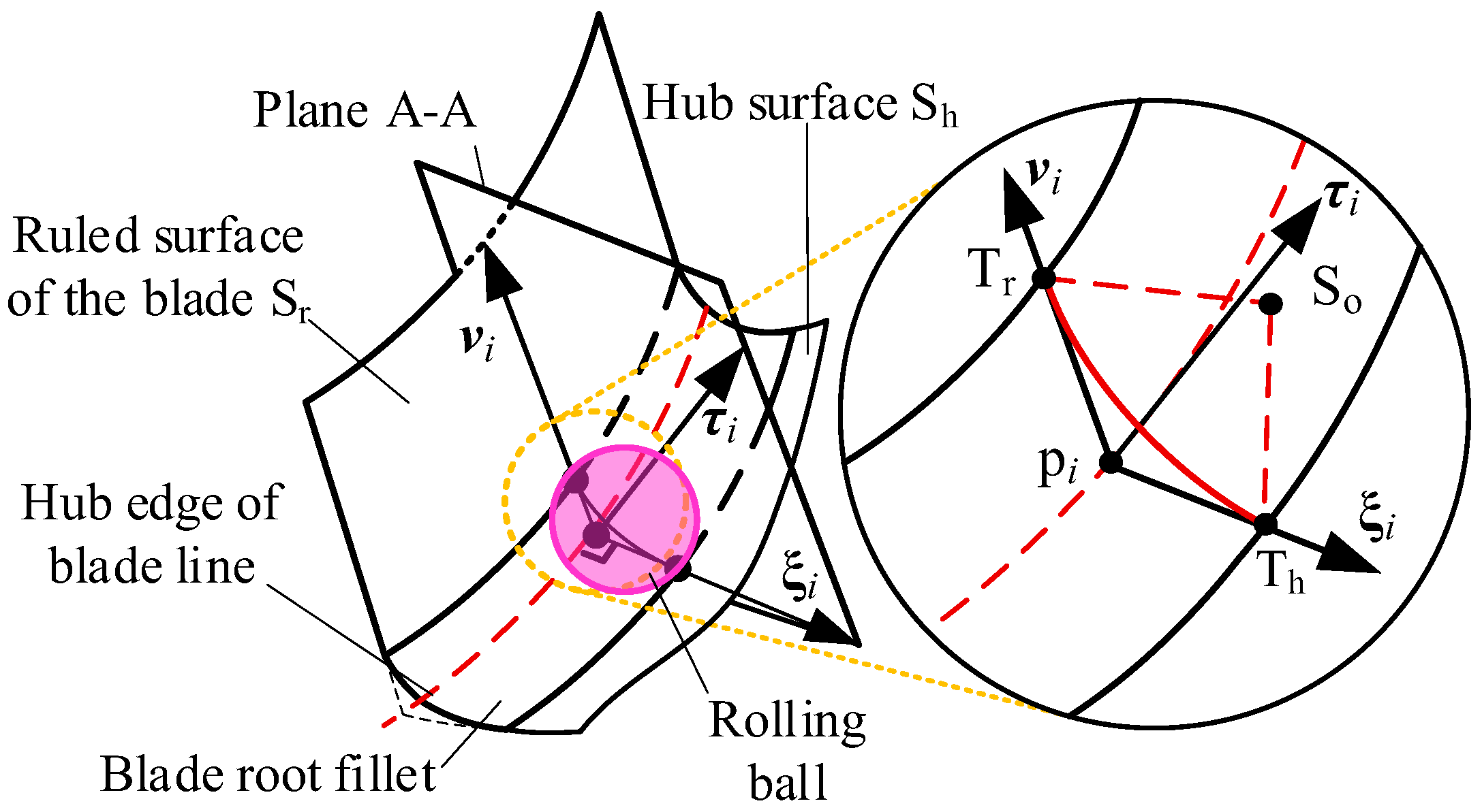
The geometric model of the blade-root fillet is created using the rolling ball model. The hub edge of blade P(
u) (where
u∈[0,1]) serves as the reference curve for constructing the blade-root fillet. Two contact surfaces adjacent to the hub edge of the blade are the ruled surface of the blade S
r and the hub surface S
h.
Figure 2 illustrates the geometric relationship at any point p
i on the hub edge of the blade in contact with a rolling ball of a specific radius R.
At any point p
i on the hub edge of blade P(
u) (where
u ∈ [0,1]), there exists a corresponding blade-root fillet curve. Let
τi represent the tangent vector at point p
i along the hub edge of the blade. Similarly, let
υi denote the generator vector of the ruled surface, where generator vector
υi is perpendicular to the tangent vector
τi:
As illustrated in
Figure 2, consider a rolling ball passing through the point p
i on the hub edge of the blade, being tangent to both the hub surface at point T
h and the ruled surface of the blade at point T
r. The center of the rolling ball is denoted as S
o. Based on the geometric relationships, we observe that S
o, p
i, T
h, and T
r are all located in the same plane, and the normal vector of this plane
τi, and the vector pointing from p
i to T
h is
ξi:
The angle α between the vector of the generator of the ruled surface
υi and
ξi can be expressed as:
The distance between the center of the sphere S
O and the tangent point T
h is
d, and the relationship between the angle α and the radius of the blade-root fillet
Rk can be expressed as follows:
Constructing the vector
λi with p
i as the starting point and the sphere center S
O as the end point can be expressed as:
From Equation (5), the coordinates of the center of the sphere S
O can be obtained, and the tangent point T
r of blade-root fillet on the ruled surface of the blade is then:
By using Equations (1)–(5), the tangent points of the blade-root fillet curve to the ruled surface of the blade and the hub surface can be found. Additionally, we can determine the center of the circle of the blade-root fillet curve. With this information, we can construct the blade-root fillet curve
Cr. The blade-root fillet surface S
rf(
u,
v) can then be obtained by sweeping the blade-root fillet curve
Cr along the hub edge P(
u) [
23]:
3. Identification Model of Overcutting Interference
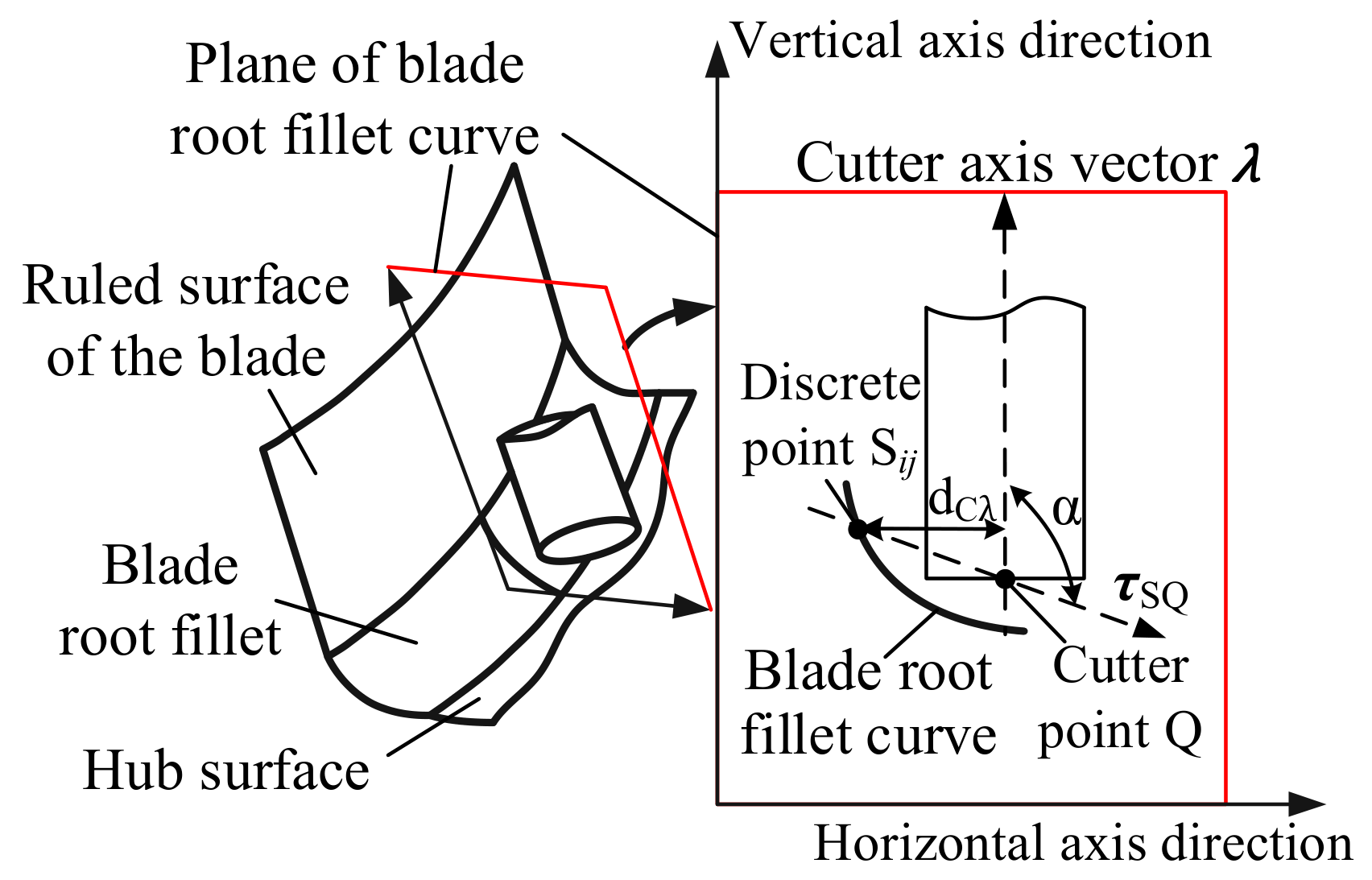
Considering the complexity of geometric interference between the plunge tool and the blade-root fillet surface, establishing an analytical model is challenging. Therefore, a mapping method for the plunge tool is proposed to simplify the geometric relationship in three dimensions. This method transforms the intricate geometric relationship between the plunge tool and the blade-root fillet surface into a relative position relationship between the plunge tool and the discrete points of the blade-root fillet curve in two dimensions, as depicted in
Figure 3.
The first step involves representing the plunge tool as a cylinder, where the bottom circle’s radius corresponds to the plunge tool’s radius, and the height represents the plunge tool’s length. Next, employing the micro-element discretization technique, the blade-root fillet surface is discretized into blade-root fillet curves. This discretization process serves as the inverse of the blade-root fillet parametric modeling. Subsequently, the blade-root fillet curve is further discretized into a set of judgment points {Sij}, where i denotes the number of blade-root fillet curve discretization, and j indicates the number of judgment point discretization. Finally, the identification of overcutting interference between the plunge tool and the blade-root fillet surface is transformed into a relative position judgment between the plunge tool and the discrete points.
In this semi-analytical model, the plunge cutter is geometrically simplified as an ideal cylinder with a sharp bottom edge and a flat end face; both the corner radius (or chamfer) and the inclination of the cutting edges are intentionally neglected. The justification for this idealization is twofold. First, a sharp-cornered, flat-ended cylinder completely envelops the actual geometry of a tool with a rounded or chamfered corner. Consequently, if the idealized tool is free of interference with the blade-root fillet, the real cutter, which is locally smaller at the bottom edge, is also guaranteed to be interference-free. This conservative assumption introduces an implicit safety margin that prevents missed overcutting detections. Second, the cutting edges on the tool face are usually inclined toward the tool body to prevent tool-center engagement, but this inclination does not alter the radial position of the outermost edge of the cutting lip. Hence, the flat-end-face assumption correctly preserves the radial location of the critical edge and adds an extra axial clearance, further contributing to the safety margin. These simplifications keep the interference test computationally efficient and industrially safe for roughing operations. The extension of the model to include realistic corner geometries and edge inclination is planned for future work aimed at semi-finishing applications.
The overcutting interference identification model, as depicted in
Figure 3, involves two position relationship cases between the discrete point S
ij and the plunge tool. The two cases are: (1) when the discrete point S
ij is inside the plunge tool, and (2) when the discrete point S
ij is located outside the tool. In both cases, we take the discrete point S
ij as the starting point and the cutter point Q (
xq,
yq,
zq) as the end point to define the vector
τCQ. At this point, the vector
τCQ intersects with the cutter axis vector
λ, forming an angle
β, as illustrated in
Figure 4. The expression for the angle
β is given by:
When
β < π/2, it indicates that the discrete point S
ij is located above the plane on which the bottom profile of the tool at the feed end (plunge circle) is situated, and when the distance from the discrete point S
ij(
xs,
ys,
zs) to the cutter point Q(
xq,
yq,
zq) is
dSQ and the distance to the cutter axis is
dSλ, then d
SQ and
dSλ can be expressed as follows:
When the distance dSλ between the discrete point Sij and the tool axis is less than or equal to the radius of the tool Rk, it signifies that the discrete point is located within the simplified cylindrical model of the plunge tool. This also means that the discrete point of the blade-root fillet is in contact with the tool, which is considered as an interference point. On the other hand, when dSλ is greater than Rk, the discrete point is positioned outside the simplified cylindrical model of the plunge tool, making it a non-interference point. If there is an interference point, it indicates that there is contact between the plunge tool and the blade-root fillet. Consequently, it is determined that overcutting interference between the tool and the blade-root fillet occurs at the current cutter position. Conversely, if there is no interference point, it is recognized that there is no overcutting interference between the plunge tool and the blade-root fillet at the current position.
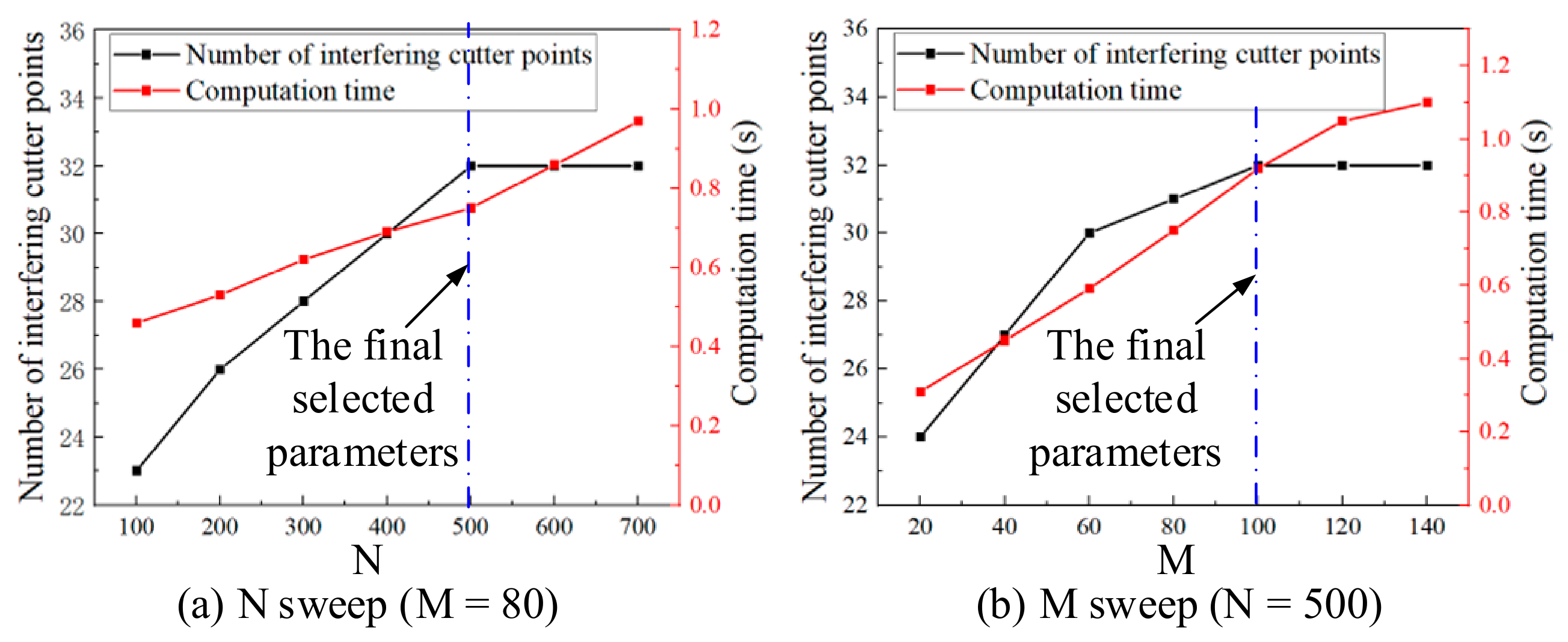
The accuracy and efficiency of the interference identification are directly influenced by the discretization strategy. The blade-root fillet surface is discretized into N fillet curves
Cri uniformly along the hub edge parameter
u with an increment Δ
u. The number of curves N is determined such that the maximum chordal deviation between two adjacent fillet curves is less than a tolerance
εu, typically set to 10% of the fillet radius
Rk. For each fillet curve
Cri, it is further discretized into M judgment points
Sij with a uniform angular increment Δθ. The number M is chosen to ensure the arc length between two adjacent points is less than
εθ, set to 1% of the fillet arc length. A convergence study, as depicted in
Figure 4, was performed, and it was found that for the impeller in this study (the impeller model is described in
Section 5), N = 500 and M = 100 provided a stable balance between computational cost (<1 s) and detection accuracy, with no additional interference points detected when further increasing the density.
4. Overcutting Interference Elimination of Plunge Milling
Currently, the resolution of overcutting interference in the plunge milling process involves the manual reduction of the plunge depth along the cutter axis vector at cutter positions where overcutting occurs. This method encounters challenges when machining impeller runners with large diameters, as the size of the chosen plunge tool is considerable. Consequently, reducing plunge depth leads to excessive residual material adhering to the hub surface. Moreover, it forms a step-like machined surface to avoid SIRD [
24], resulting in a significant volume of residual material. This scenario poses severe complications for subsequent semi-finishing and finishing processes, hampering the overall efficiency of plunge milling in impeller machining.
To address the aforementioned problem, a method for overcutting interference elimination is proposed, as illustrated in
Figure 5.
Initially, the cutter positions (cutter point O
itf and cutter axis vector
Vitf) that should be excluded from overcutting interference are extracted based on the identification result. Subsequently, the corresponding generator of the ruled surface vector, denoted as
l(
ui), is determined in accordance with the cutter axis vector:
Compute the vector
Vδ by passing through the cutter point O
itf and being perpendicular to
l(
ui). Consider
Vδ as the offset direction, and adjust the plunge tool by a distance Δd until it precisely aligns with the blade-root fillet without encountering overcutting interference. The resulting offset distance is
δ, as depicted in
Figure 6. This method ensures that the plunge circle remains in the same plane before and after the adjustment, effectively avoiding an increase in residual material on the hub surface. However, it may lead to an increase in residual material on the ruled surface of the blade, which requires further investigation to assess its impact on the machining process.
For the semi-finishing machining of the ruled surface of the blade, side milling is commonly employed, especially for thin-walled parts machining, while ensuring avoidance of chattering during the process [
25]. To achieve this, the milling width should not exceed W
max. Additionally, the distance d from the adjusted cutter axis to the ruled surface of the blade is calculated. If
dλ <
Wmax +
Rk +
ε, where
Rk is the current tool radius and
ε is the machining allowance, it indicates that the adjusted cutter position satisfies the requirements for subsequent semi-finishing machining.
Conversely, if dλ > Wmax + Rk + ε, it necessitates the arrangement of additional plunge milling processes after the cutter position adjustment. In these processes, the plunge depth along the cutter axis vector of the pre-adjusted cutter position is reduced until no overcutting interference occurs at the blade-root fillet. The resulting adjusted cutter position is then used for the additional plunge milling processes.
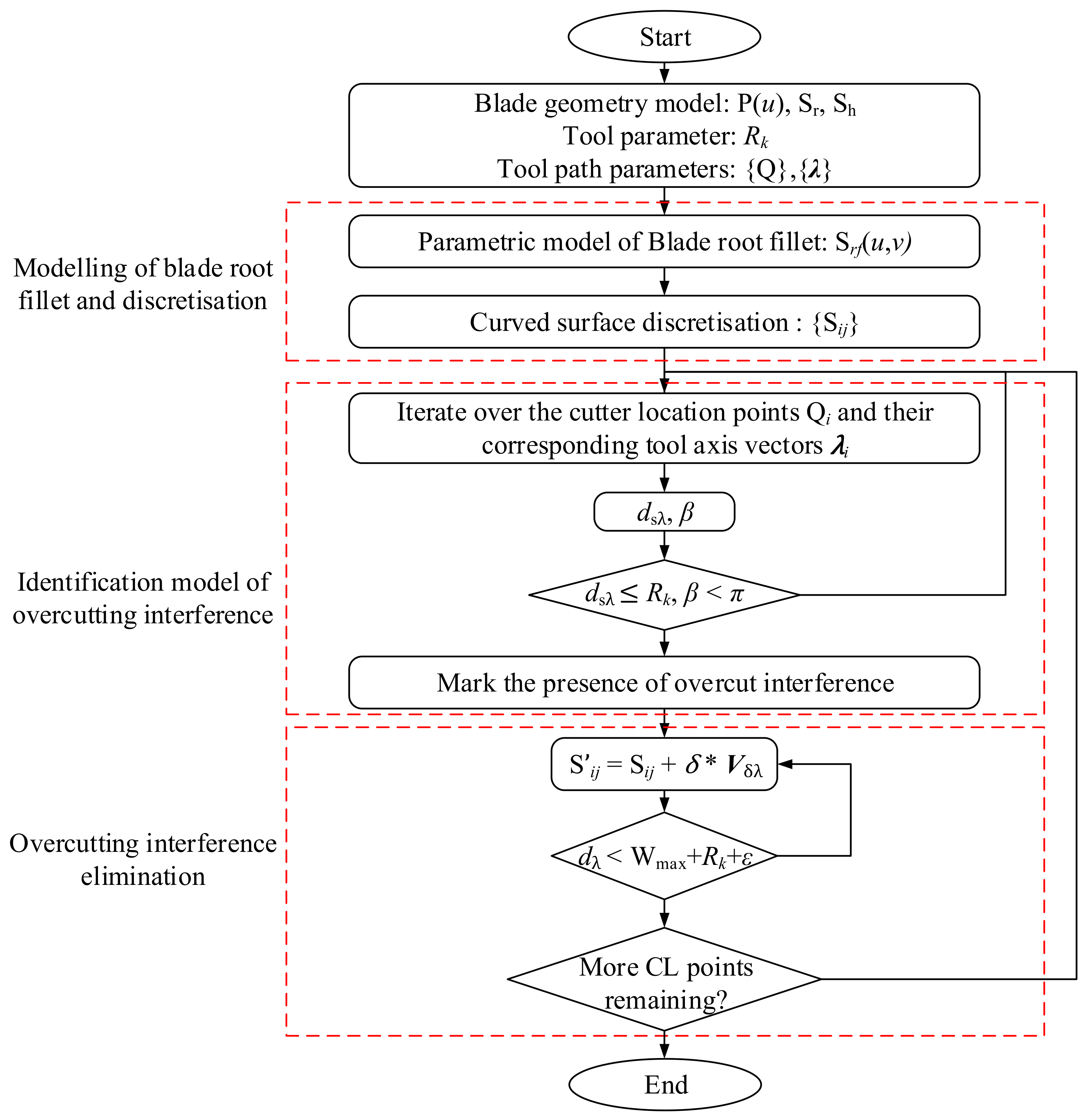
To provide a clear and integrated overview of the proposed methodology, from geometric modeling to the final interference-free tool path generation, the complete algorithm is summarized in the flowchart shown in
Figure 7. The workflow consists of three main stages: (1) parametric modeling and discretization; (2) interference identification; and (3) interference elimination and path regeneration.
The entire process is automatic: it takes the initial plunge milling tool path (planned based on blade boundaries) and outputs a modified set of tool paths free from blade-root fillet overcutting. The simulation and experimental validation are performed in MATLAB 2016b and UG NX 11.0, as detailed in
Section 5.
5. Simulation and Experimentation
The simulation aims to validate the reliability of the two objectives as follows: (1) confirming the reliability of the established parameterized model of blade-root fillet and the overcut interference identification model; and (2) verifying the effectiveness of the overcut interference elimination method in reducing excessive residual material.
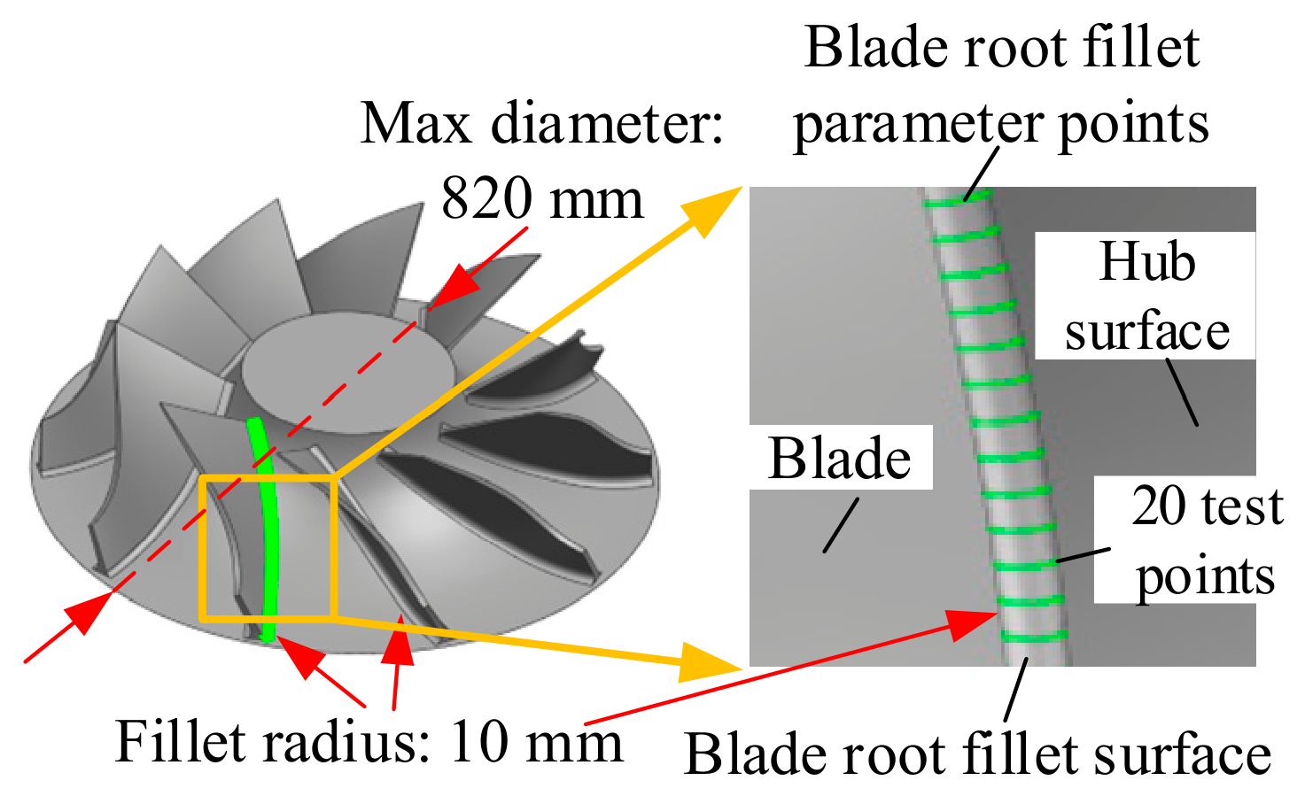
A certain type of aviation impeller is used as a simulation example; the maximum diameter of this impeller is 820 mm, the number of blades is 10, and the radius of the blade-root fillet is 10 mm. A total of 20 test points were randomly selected uniformly from the blade-root fillet parameter points to validate their accuracy against the corresponding data points in the 3D model, as shown in
Figure 8.
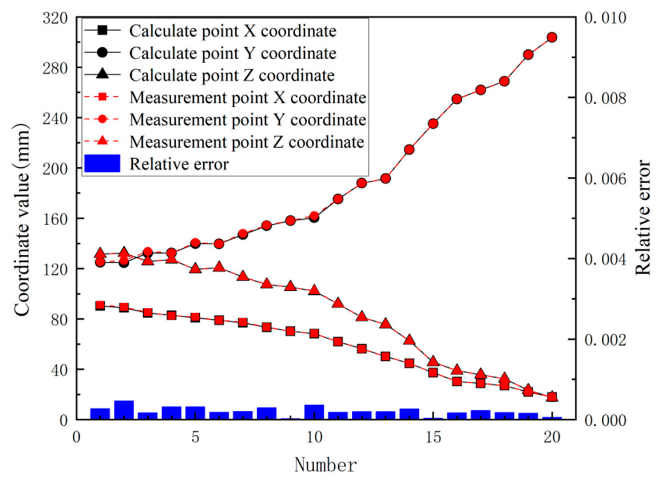
By comparing the coordinates of the parameter points extracted from the parametric modeling of the blade-root fillet with the data points of the blade-root fillet 3D model in the UG software, the results of this comparison are depicted in
Figure 9. The results demonstrate that among the 20 sampled parameter points, the maximum error in the X-direction coordinate value is 0.037%, the maximum error in the Y-direction coordinate value is 0.012%, the maximum error in the Z-direction coordinate value is 0.026%, and the maximum error in relative distance is 0.046%. It is worth noting that the errors of the 2nd, 3rd, and 10th selected points appear relatively large due to artificial measurement errors. It should be noted that the relative error along the Y-axis appears to increase slightly with the sampling index, which is in contrast to the trends observed along the X and Z axes. This behavior arises from the geometric location of the sampled fillet near the global Y-axis, where the hub edge curvature is high. As the sampling points approach this region, the absolute modeling error in the Y-direction increases, whereas those in X and Z decrease because of the diminishing coordinate magnitudes. However, the relative error is defined as the absolute error divided by the measured coordinate; since the Y coordinate itself also grows considerably, the resulting Y-direction relative error does not show a systematic monotonic trend but remains randomly distributed. All relative errors remain within an extremely low range (<0.05%), confirming that the parametric model possesses high and spatially uniform accuracy. Overall, all errors are well within 0.1%, providing strong evidence that the established parametric modeling accuracy of the blade-root rounding is reliable.
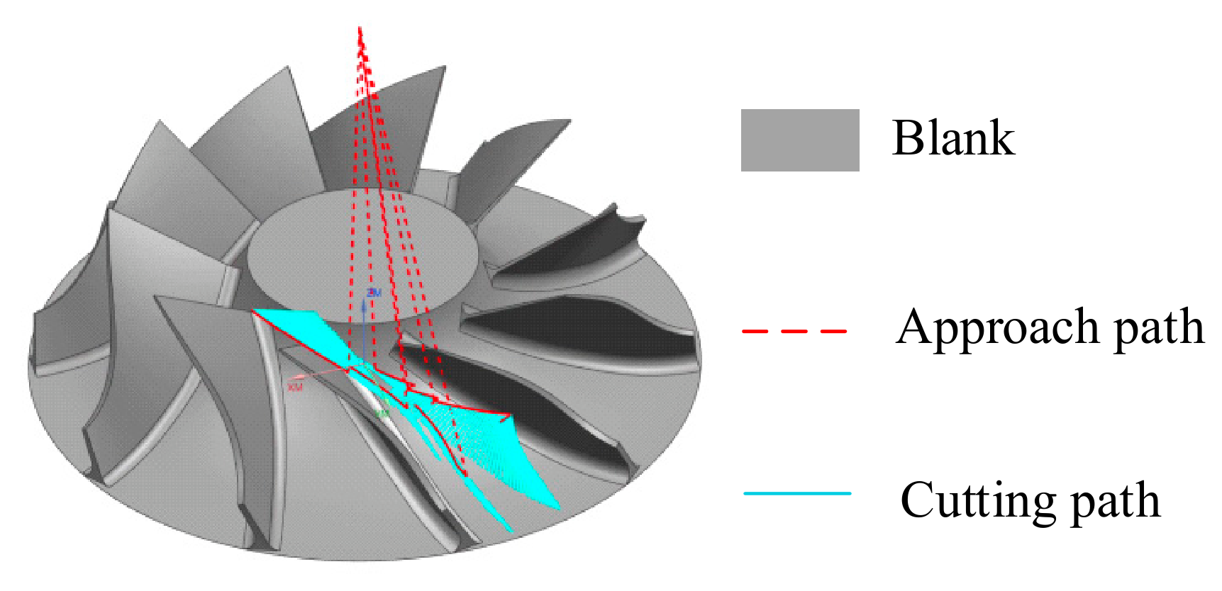
The plunge milling tool path is planned with reference to the blade boundaries on both sides of the runner [
16], and the planned tool path is depicted in
Figure 10.
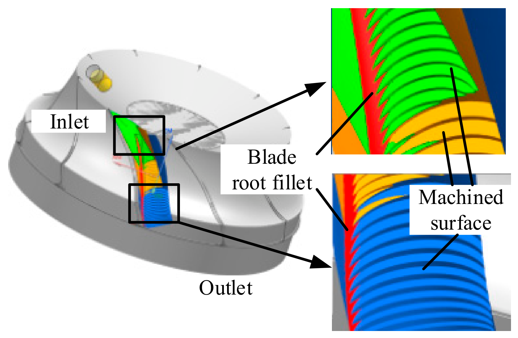
The tool path of plunge milling corresponding to the left blade is taken as an example, and the overcut interference is calculated for this tool path, resulting in an extraction of the identification result. The entire process is performed in Matlab and takes approximately 1.26 s. Subsequently, the plunge milling tool path is imported into UG for machining simulation, as depicted in
Figure 11. In the figure, the red region denotes the blade-root fillet region, while the blue, yellow, and green regions indicate the plunge-milled surfaces for tool diameters of 80 mm, 60 mm, and 42 mm, respectively. The simulation process, along with manual judgment, requires a total time of approximately 600 s.
For better observation, the blade-root fillet surface is displayed in green. The recognition results and simulation results are summarized in
Table 1, where each number represents the serial number of the plunge milling process. “Rec” denotes the recognition result, while “Sim” denotes the simulation result. “Y” denotes the occurrence of overcutting interference, while “N” indicates no overcutting interference. The comparison between the identification results and the simulation results shows consistency, validating the reliability of the overcutting interference identification model.
Table 2 provides a quantitative analysis of the identification performance, treating the CAD simulation results as the ground truth. The proposed semi-analytical model achieved 100% precision and recall, indicating perfect agreement with the simulation in this case study. Furthermore, the interference depth, defined as the maximum penetration distance of a discrete point inside the tool cylinder, was calculated. The average absolute error between the maximum interference depth identified by our model and that measured in the simulation was 0.01 mm, demonstrating a high degree of quantitative accuracy.
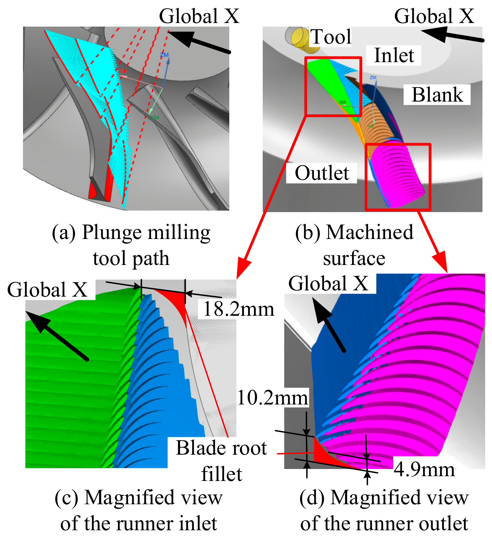
After extracting the position data of plunge milling tool locations where blade-root fillet overcut interference occurs, overcut interference elimination is performed. The adjusted plunge milling tool path is shown in
Figure 12a. This adjusted tool path modifies the initial plunge milling tool path and incorporates an additional row of plunge milling tool paths according to the method described in
Section 4, aiming to minimize residual material. The machining simulation results after tool path adjustment are presented in
Figure 12b–d. The simulation results confirm that no blade-root fillet overcut interference exists. At the runner inlet, the machined region corresponding to the adjusted initial plunge milling tool path is shown in dark blue, while the region corresponding to the additional tool path is shown in purple. At the runner outlet, the machined region corresponding to the adjusted initial plunge milling tool path is shown in green, while the region corresponding to the additional tool path is shown in sky blue.
At the runner outlet, the machined surface exhibits a stepped profile, which is characteristic of plunge milling [
2]. The residual material heights were measured at (1) the location closest to the blade-blade-root fillet junction and (2) near the midpoint of the blade-root fillet, yielding values of 10.2 mm and 4.9 mm, respectively. These values indicate that the machined region did not contact the blade-root fillet. At the runner inlet, the residual material height measured near the blade-blade-root fillet junction is 18.2 mm, which is substantially larger than the blade-root fillet radius of 10 mm. This occurs because the plunge milling depth must be reduced to avoid SIRD (the sudden increase of radial depth) [
17], resulting in considerable residual material. It is worth noting that in
Figure 12d, the blue region represents the adjusted tool path at the runner outlet, and this adjusted path can be observed to closely coincide with the additional tool path shown in purple. This spatial proximity indicates that the adjusted tool path at the outlet is offset by only a small distance (3 mm) perpendicular to the tool axis vector, yet it effectively prevents excessive residual material on the machined surface. Moreover, the additional plunge milling tool paths only need to remove material near the machined surface and can be executed with shorter feed paths; therefore, the extra plunge milling operation time is relatively small. For the impeller example presented in this paper, the additional machining time increases by only approximately 26%.
Due to the significant degree of blade twist, a considerable amount of residual material is inevitable at the outlet to ensure proper shaping of the blade. This excess material requires additional removal methods, which are not discussed in this paper. Instead, the focus is on comparing the size of the residual material resulting from different methods used to avoid blade-root fillet overcut interference. If the depth-reduction method is adopted, once overcut interference is identified, the plunge milling depth at the position closest to the runner outlet must be reduced by at least 10 mm. For the subsequent plunge milling operations intended to avoid SIRD, the plunge milling depth must also be no less than 10 mm. Software calculations show that, compared with the method proposed in this paper, the depth-reduction approach would generate a total of 153,264 mm
3 of additional residual material; these volumetric values were calculated using the UG software’s Boolean subtraction function, by subtracting the simulated machined solid model from the original design solid model of the impeller runner. Such a large volume of residual material poses severe challenges for subsequent machining stages. In contrast, by introducing an additional row of plunge milling tool paths according to the method described in
Section 4, the extra residual material is reduced to 52,324 mm
3. This comparison fully demonstrates the advantage of the blade-root fillet overcut interference elimination method proposed in this paper. While effectively avoiding overcut interference, this method minimizes the accumulation of excessive residual material as much as possible, thereby ensuring the machining efficiency of plunge milling.
Based on the above results, the introduction of an additional row of tool paths increases the plunge milling roughing time by approximately 26%. This estimation is based on the sum of the shorter feed paths for the additional cuts. While this represents a direct increase in roughing time, it fundamentally reduces the excessive residual material from 153,264 mm3 to 52,324 mm3. This 66% reduction in residual volume translates into a significantly lower workload for the subsequent semi-finishing and finishing operations, which typically use smaller, less efficient ball-end cutters. The avoidance of sharp, uneven stock also contributes to a more stable cutting process, potentially reducing tool wear and the risk of tool chipping in follow-up stages, thus favoring overall process economics.
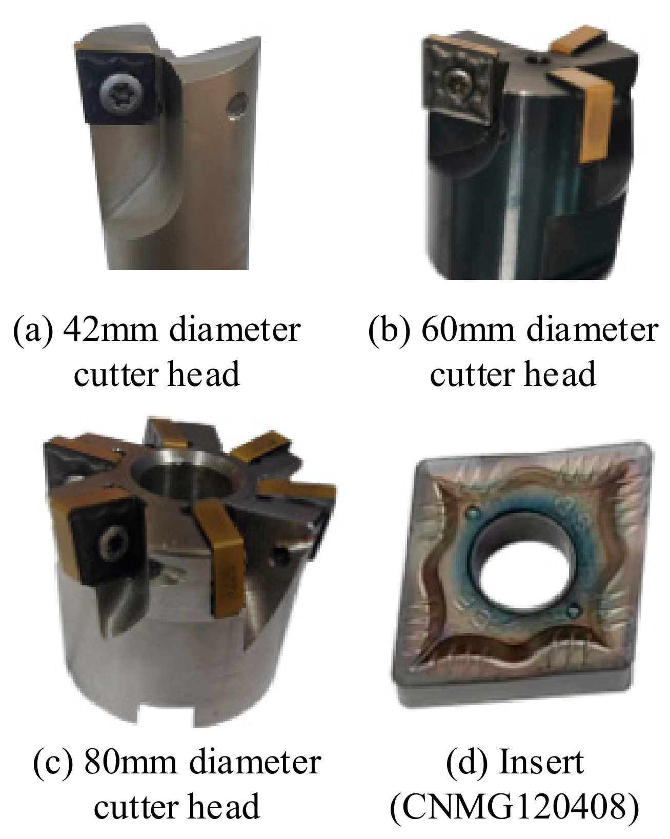
Machining tests were conducted on a DMG DMU 100P 5-axis CNC machining center using an FV520B-S1 stainless steel impeller forging (maximum diameter 820 mm). Three custom-designed plunge milling cutters with diameters of 80 mm, 60 mm, and 42 mm were employed, as shown in
Figure 13. The number of teeth was chosen as 6, 3, and 2, respectively, so that the feed rate could be kept sufficiently high when the spindle speed decreased with increasing diameter, thus preserving the material removal rate. All cutters were equipped with SANDVIK CNMG120408-PM inserts (mill-grade generalization of the turning grade, 80° rhombic shape, nose radius 0.8 mm). The cutting speed was held constant at 150 m/min. The radial depth was set to 10% of the cutter diameter (8 mm, 6 mm, and 4.2 mm). After machining, the residual material dimensions were measured with a Zeiss PRISMO coordinate measuring machine (CMM) equipped with a scanning probe. The machine’s maximum permissible error is MPEE = (1.2 + L/400) µm. Each reported value represents the average of three repeated measurements, and the expanded measurement uncertainty (k = 2) was within ±0.05 mm.
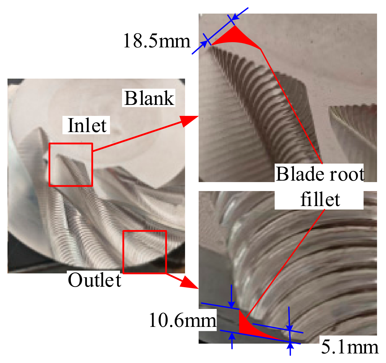
The plunge milling tool paths used in the experiment were identical to those in the simulation, and the machining results are shown in
Figure 14. At the runner inlet, the measured maximum residual material height is 18.5 mm. At the runner outlet, the residual material heights were measured at (1) the location closest to the blade–blade-root fillet junction and (2) near the midpoint of the blade-root fillet, yielding values of 10.6 mm and 5.1 mm, respectively. These actual machining results differ from the simulation results by 0.3 mm, 0.4 mm, and 0.2 mm, respectively, which may be attributed to manual measurement errors and machining system errors. Overall, the deviations are small and within an acceptable range. The experimental results are in general agreement with the simulation results, confirming the effectiveness of the blade-root fillet overcut interference elimination method proposed in this paper.
The proposed method is suitable for implementation as a specialized plug-in for impeller machining within commercial CAM systems. Its core algorithms, the automatic identification and elimination for overcut interference at blade-root fillet, operate on parametric curve and surface data, which are accessible through standard CAD/CAM APIs (NX, CATIA). A possible workflow consists of three steps. First, the API extracts the blade’s hub edge, ruled surface, and hub surface. Second, the parametric fillet model is constructed and discretized using the proposed algorithms implemented in a compiled dynamic-link library (DLL) for computational efficiency. Third, upon importing an initial plunge milling tool path, the DLL processes the path through the interference identification and elimination module. Finally, the adjusted and additional tool paths are written back into the operation navigator of the CAM session.
In summary, this study demonstrates that: (1) the rolling-ball-based parameterized model can accurately represent the blade-root fillet with less than a 0.1% error; (2) the semi-analytical model can reliably identify overcutting interference with high accuracy (100% precision/recall) and computational efficiency (<1.3 s); and (3) the proposed tool-position-adjustment method can effectively eliminate the identified overcutting while reducing residual material by 66% compared to the depth-reduction method, thus fully leveraging the high efficiency of plunge milling.
However, several limitations of this study should be acknowledged. First, the proposed method assumes a constant fillet radius; for variable-radius fillets, the parametric model would need to be extended. Second, the adjustment of tool positions introduces additional tool paths, and while the net effect on process economics appears positive, a detailed cost-benefit analysis was not performed. Third, the method currently does not account for tool wear or deflection, which could affect the actual interference state during machining. Future work will focus on extending the method to variable fillet radii and integrating dynamic cutting forces and tool wear models to enhance its industrial applicability.