


Abstract
The dual-arm cooperative operation mode can effectively address the problems of insufficient load capacity and limited motion flexibility of traditional single-arm robots during the installation of construction boards. However, the selection of the end-effector grasping position of dual-arm robots will significantly affect their motion performance during handling operations. To address this issue, this study proposes an end-effector grasping strategy for sheet installation in the dual-arm cooperative operation mode of a dual-arm robot, which determines the optimal grasping position to ensure the robot’s good operational performance. We developed a dual-arm robot prototype for board installation and established a kinematic model of the robot’s manipulators. Based on the dexterity index’s service sphere, we obtained the dexterity envelope surfaces of the robot end-effector at different grasping distances and analyzed the relationship between grasping distance and dexterity. The mechanical model of the robot was established, and simulations were performed for each joint. The effects of different grasping points on the torque, stiffness, and stability at the robot’s key points were investigated, and the end-effector grasping range of the robot with optimal mechanical performance was analyzed. Finally, the proposed robot grasping strategy was verified on the robot prototype. The results demonstrate that the strategy is feasible and effective, helping to improve the robot’s operational performance.
1. Introduction
With the continued development of the construction industry, demand for large prefabricated building components, such as large-sized construction boards, has grown steadily [1,2]. Construction board installation is one of the most frequent and arduous links in construction. Currently, it mainly relies on manual handling and assembly, which is characterized by low operational efficiency, high labor intensity, and high safety risks [3]. Construction robots have become an important research direction for improving the intelligence level of construction [4].
Current building board installation robots predominantly use single-arm configurations [5]. Notable examples include the ALC wall board installation robot developed by Li et al. [6] and the board installation robot designed by Hebei University of Technology [7]. Although single-arm configurations can meet the requirements of automated assembly, they often face challenges, including limited load capacity and a constrained workspace, when handling large or heavy building boards [8]. To address these challenges, we designed and developed a dual-arm robot for installing construction boards. By employing a dual-arm cooperative operation mode, the robot can effectively increase both the workspace and load capacity in practical construction operations [9,10].
During dual-arm cooperative operations, the selection of end-effector grasping positions significantly affects the dexterity and mechanical performance of the robotic system, which in turn determines its overall operational performance [11,12]. Robot dexterity is defined as the ability of a robotic system to perform precise, coordinated, and multi-degree-of-freedom tasks in complex environments [13]. There are various evaluation methods for robot dexterity. Vinogradov et al. [14] introduced the concept of the service sphere to define the robot dexterity index, providing a more intuitive representation of manipulative capability. Guohua et al. [15] analyzed the kinematic accuracy across various postures within the workspace, using dexterity indices derived from the Jacobian matrix. Leon et al. [16] analyzed the dexterity of robotic grasping based on tactile perception, aiming to improve the sensitivity in various grasping postures. Using dexterity-based evaluation indices, the team led by Ruonan assessed the operability of dual-arm robot cooperative operations and determined the optimal grasping posture for the dual-arm robot [17]. Mira et al. [18] evaluated the grasping dexterity of compliant robots using a Bayesian neural network, thereby quantifying their sensitivity to object grasping. Gosselin et al. introduced a kinematically redundant planar parallel mechanism, significantly expanding the robot’s dexterous workspace [19]. Guo et al. proposed a novel dexterity analysis method for 5-DOF manipulators, thereby broadening the evaluation framework for specific non-fully degree-of-freedom mechanisms [20]. Mechanical properties encompass force transmission, stiffness, and end-effector load capacity, reflecting the mechanism’s intrinsic characteristics. The selection of grasping points directly affects the forces experienced by each joint, and suboptimal grasping positions may damage the robot [21]. Liu et al. [22] proposed a novel formulation of mechanical indices for evaluating the singularity of parallel robots. Based on screw theory, Liu et al. [23] calculated the force transmission index in the motion of parallel robots and proposed a novel method for force/motion transmission in redundantly actuated and over-constrained parallel robots. Pei et al. [24] defined the magnitude and direction of the robot’s end-effector load capacity as the objective function and analyzed the optimal grasping points. Siyang et al. [25] established evaluation indices for input motion and force transmission performance based on screw theory and analyzed the robot’s kinematic performance. Nouri Rahmat Abadi et al. introduced an innovative parallel mechanism; comparative analyses with conventional parallel robots demonstrated that integrating kinematic redundancy significantly enhances robotic performance [26].
Although previous studies have achieved progress in optimizing either dexterity or mechanical performance separately, few have integrated both factors to enhance the operational performance of dual-arm robots during collaborative tasks. Furthermore, under heavy-load operating conditions, existing grasping-point selection strategies often exhibit inadequate mechanical performance. Therefore, it is necessary to develop an optimized dual-arm grasping strategy for complex, heavy-load operation scenarios.
To solve the problem of selecting the initial posture of a dual-arm sheet installation robot when grasping sheets under the dual-arm cooperative operation mode, this study proposes a dual-arm cooperative grasping strategy. This strategy can determine the optimal grasping position for the dual-arm robot, with mechanical performance as the primary objective and dexterity as the secondary objective. In this study, the mechanical performance of the robot was the primary evaluation criterion. By varying the robot’s grasping point, changes in stress, stiffness, and amplitude at different points were analyzed, and the optimal grasping range was determined. In addition, dexterity in robot operation was selected as the evaluation criterion. By varying the robot’s grasping point position, the robot’s dexterity at different positions was analyzed. Finally, the optimal grasping position of the robot was determined. In this process, both the mechanical performance and the robot’s motion dexterity were considered.
2. Dual-Arm Robot for Construction Board Installation
We developed a dual-arm robot for board installation, which consists of a mobile base equipped with two 7-DOF arms. The two robot arms are independent, and their bases are installed on the left and right sides of the chassis, enabling both single-arm standalone operation and dual-arm cooperative operation. The robot’s arms use a hybrid serial-parallel mechanism. This configuration can effectively improve structural stiffness and load capacity while maintaining the arms’ dexterity and workspace. The hybrid mechanism is composed of multiple parallelogram mechanisms connected in series, with electric cylinders as the driving elements.
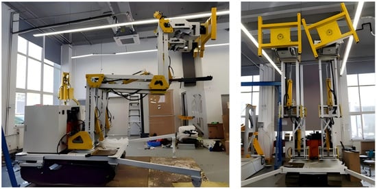
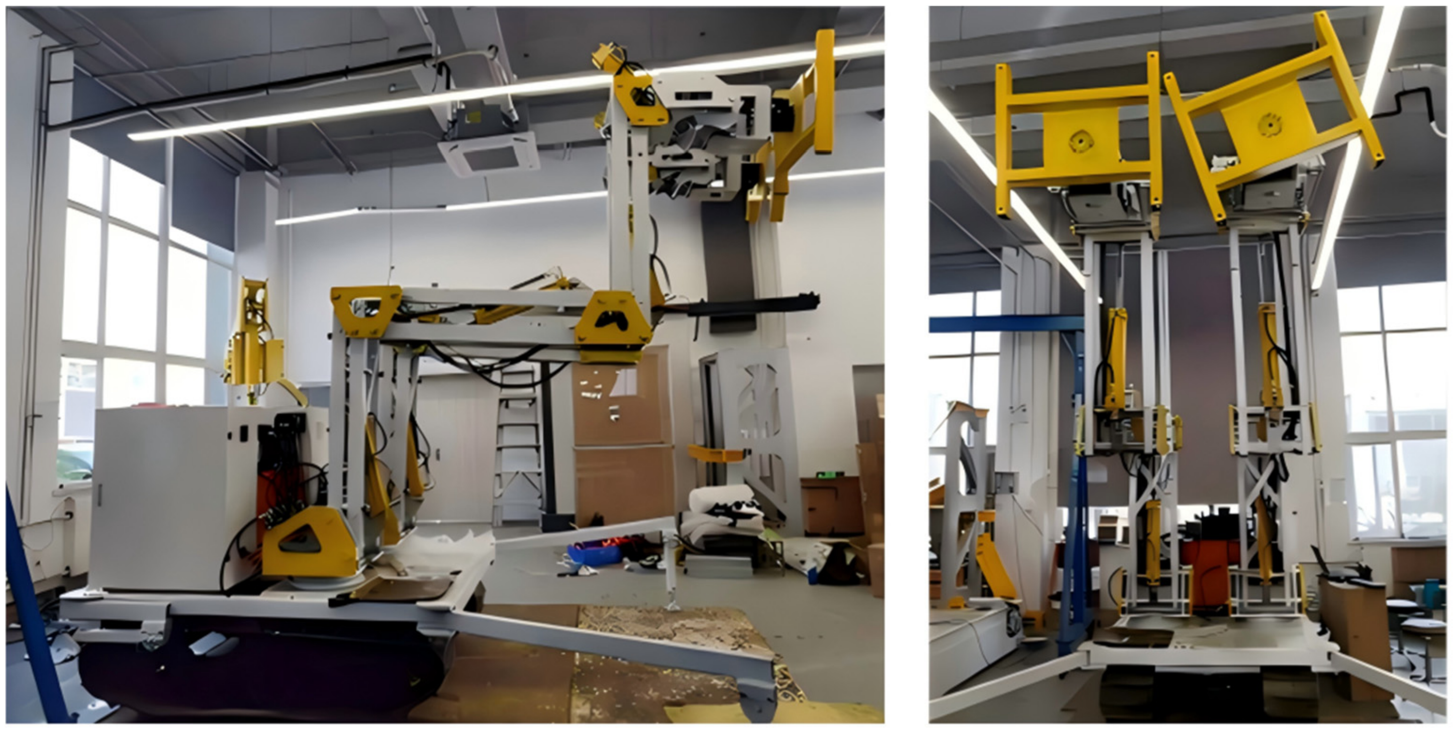
The developed manipulator is a seven-degree-of-freedom (7-DOF) hybrid manipulator. The first four degrees of freedom (DOFs) of the 7-DOF arm comprise one revolute joint and three parallelogram mechanisms, which facilitate adjustment of the end-effector’s spatial position. The last three degrees of freedom are revolute joints, which collectively constitute the wrist mechanism and are responsible for end-effector orientation adjustment. During a dual-arm cooperative operation, the entire assembly forms a redundantly actuated system. The motion synchronization and tracking accuracy of both arms are ensured through a proprietary actuation configuration strategy and control algorithm developed by the research team. Meanwhile, the mobile chassis of the dual-arm robot employs a tracked configuration, enabling it to adapt to most complex ground conditions encountered in practical construction operations. The robot is shown in Figure 1. The performance indices of the dual-arm robot during board installation are shown in Table 1.
Figure 1.
The dual-arm robot during construction board installation.
Table 1.
Robot performance indicators.
3. Dexterity Analysis
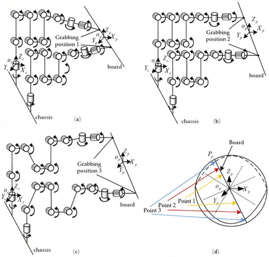
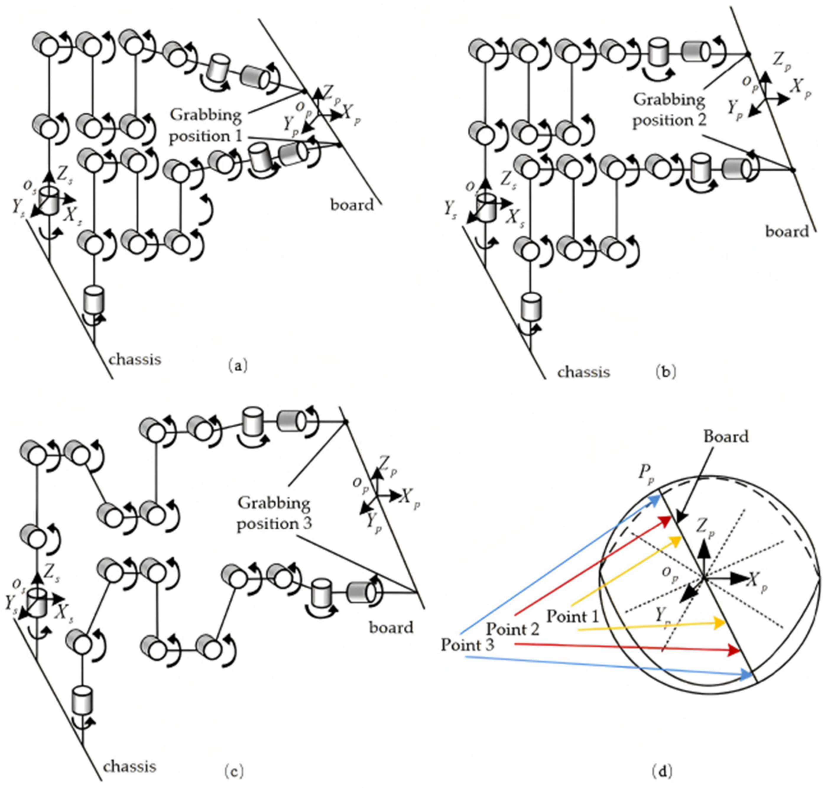
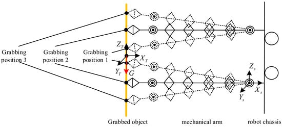
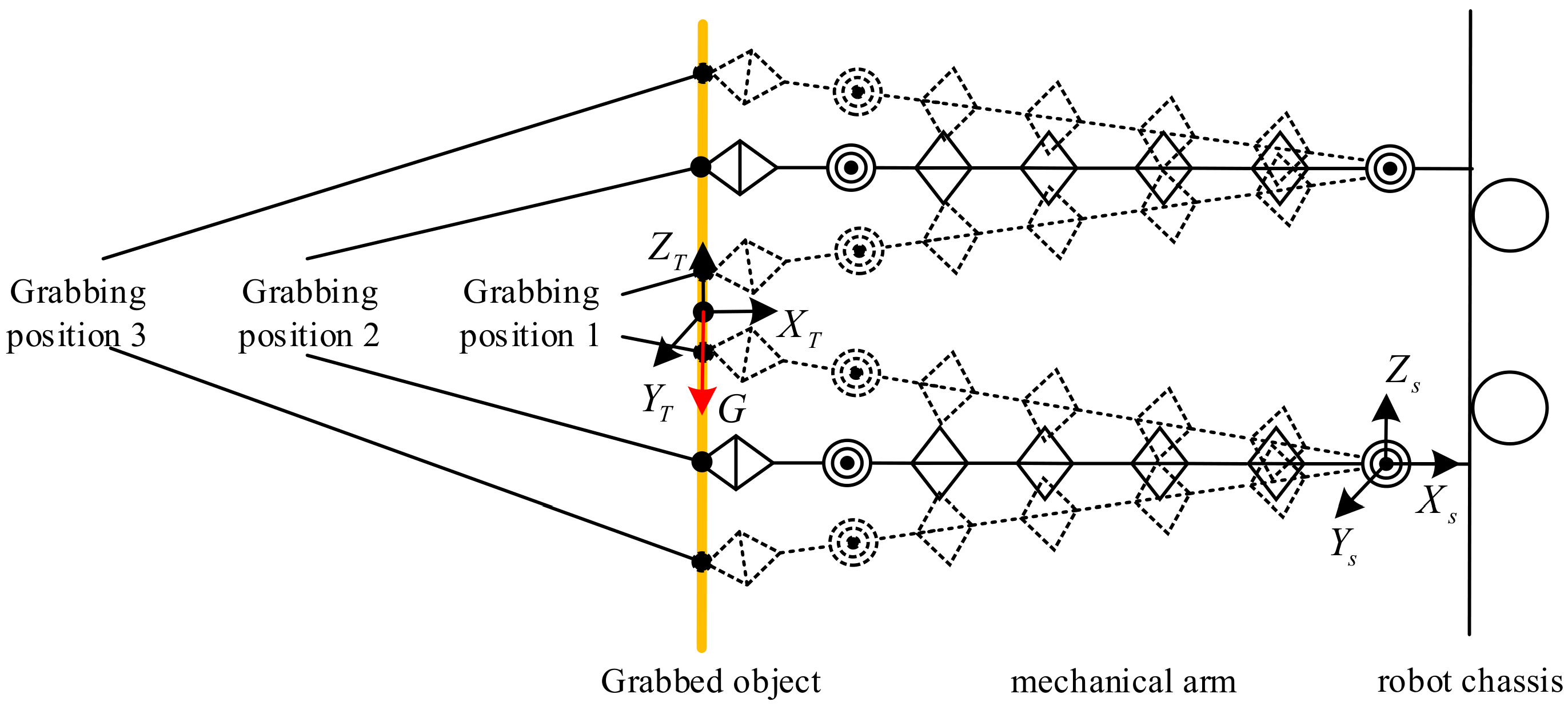
Dexterity refers to the total set of orientations that a robot manipulator can achieve while maintaining a fixed point on the end effector. During dual-arm cooperative operations, different end-effector grasping positions yield distinct robot grasping poses, as shown in Figure 2. Variations in robot grasping pose affect the robot’s dexterity during motion.
Figure 2.
(a) Grasping position 1; (b) grasping position 2; (c) grasping position 3; (d) variation in end-effector pose under different grasping positions.
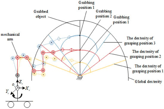
Based on the dexterity metric proposed by Vinogradov et al. [14], dexterity is defined in this study as the ratio of the reachable orientation spherical area to the total spherical area at a fixed end-effector position. Let denote the origin of the motion space of the two arms during plate grasping, and let denote a point at the plate edge. The end-effector grasping point is assumed to lie on the line segment connecting and , as illustrated in Figure 2d.
The two manipulators mounted on the dual-arm robot have identical configurations and are symmetrically arranged on the left and right sides of the mobile platform. Therefore, to simplify the calculation, a single manipulator and half of the plate are simplified as a spherical-joint model. The spherical joint has three rotational degrees of freedom, and its center is located at point , as shown in Figure 3. In Figure 3, the spherical area corresponding to each grasping point reflects the dexterity of the end-effector; the larger the spherical area, the higher the dexterity. On this basis, the robot’s dexterity is calculated. Given the robot’s symmetry and actual operating conditions, mutual interference may occur between the two arms during cooperative operations. Therefore, absolute-value treatment is required in the calculation.
Figure 3.
The dexterity diagram of different grasping position points.
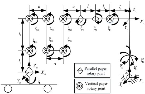
The kinematic model of a single manipulator and the spherical-joint linkage is established, as shown in Figure 4. As shown in the figure, the inertial coordinate system of the manipulator is defined as , the inertial coordinate system of the spherical-joint linkage is defined as , and the two mechanisms share the same tool coordinate system, denoted as . The parameters in the figure are shown in Table 2.
Figure 4.
A reference configuration diagram of the robot arm.
Table 2.
The design parameters of the robot arm.
Under the reference configuration shown in Figure 4, the initial configuration of each joint of the manipulator is defined as follows:
In the above equation, denotes the homogeneous transformation matrix of the manipulator in its initial (home) configuration.
Based on the reference configuration diagram of the robot arm, the screw coordinates of each joint of the manipulator are established as follows:
The position vectors of the joint-axis points of the manipulator can be obtained as follows:
Based on the product-of-exponentials formula and the corresponding equation in screw theory, the coordinate transformation matrix of each joint can be derived. The positive solution of kinematics is
where represents the pose transformation matrix when the joint angle is θ.
Then, the kinematics of the spherical-joint linkage is derived. Under the reference configuration shown in Figure 4, the initial configuration of each joint of the spherical-joint linkage is defined as follows:
The screw coordinates of each joint of the spherical-joint linkage are established as follows:
The position vectors of the joint-axis points of the spherical-joint linkage can be obtained as follows:
The positive solution of kinematics is
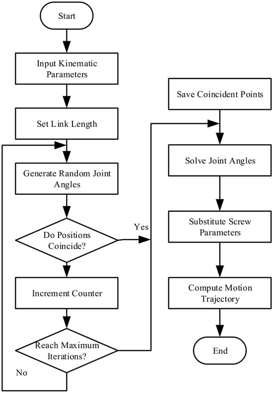
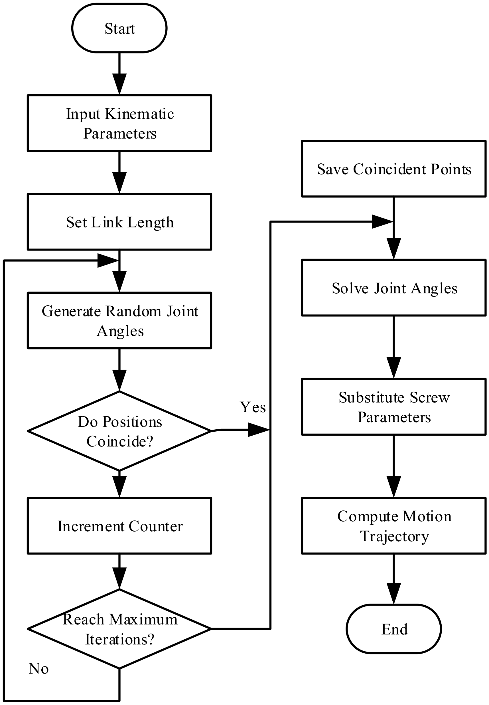
The dexterity solving process of the manipulator is shown in Figure 5. In this process, the kinematic transformation matrix derived above serves as the input to the solution procedure, in which the rod length of the spherical-joint mechanism is treated as a variable. Subsequently, n iterations are performed, in which the rand(1) function is used to randomly generate values within the ranges of the motion-joint angles of the two mechanisms. Points with identical positions are then identified and stored, and the loop terminates accordingly until all iterations are complete. Finally, based on the stored coincident-position data, the corresponding joint angles of the spherical joint are determined. These angles are then substituted into the kinematic parameters of the original-length, single-rod spherical-joint mechanism to obtain the dexterity of the single arm.
Figure 5.
The dexterity-solving flowchart for different grasping positions.
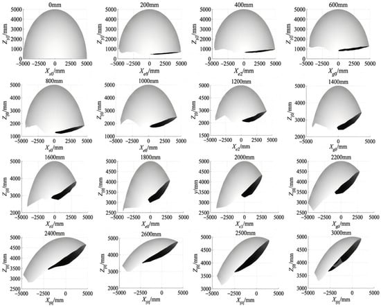
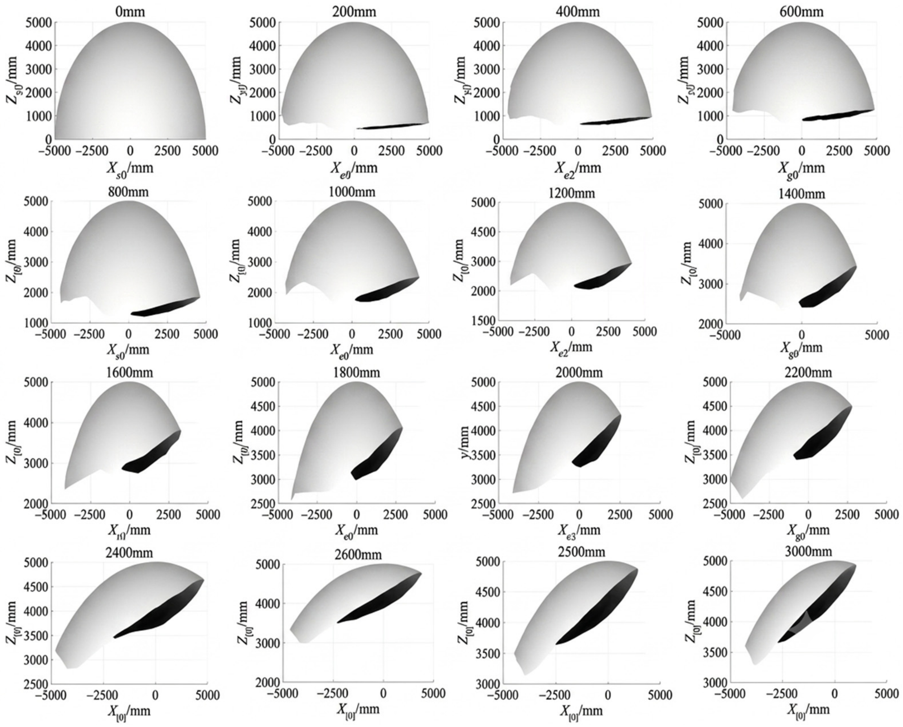
A simulation analysis was conducted on the dexterity of the dual-arm robot when the two arms jointly grasp the building board at different positions. In the simulation, the center point between the two dual-arm end-effectors during grasping was defined as the initial grasping point. An inertial coordinate system of the spherical joint was established at the center point between the two dual-arm end-effectors. In the simulation, 200 mm was used as the unit interval to vary the grasping position. The envelope surfaces formed by the point’s motion trajectory were analyzed as the grasping position varied from 0 to 3000 mm. The variation in the trajectory envelope surface reflects the manipulator’s dexterity. The simulation results are shown in Figure 6. Absolute value treatment was applied to the results. When the envelope surface forms a complete hemisphere, the manipulator is considered to achieve full dexterity.
Figure 6.
A dexterity envelope diagram of different grasping positions.
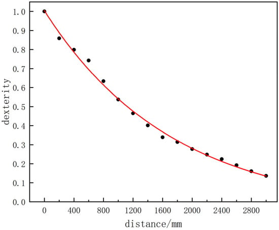
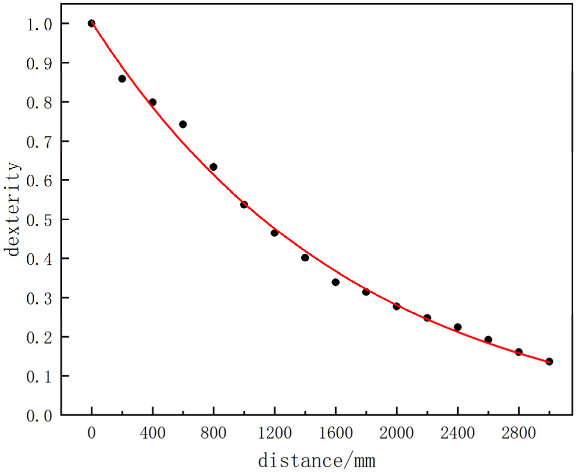
The simulation results indicate that when the grasping point is located at the center of the spherical-joint mechanism, the envelope surface forms a complete hemisphere, and the dexterity reaches its maximum. The envelope surface area obtained from the simulation results was extracted to calculate dexterity at each grasping position. The resulting data were then fitted, and the results are presented in Figure 7.
Figure 7.
Dexterity at different positions.
As the grasping point gradually moves away, the envelope surface progressively decreases and dexterity correspondingly deteriorates. Therefore, it can be concluded that, during board-grasping operations, the relative distance between the two end-effectors is negatively correlated with dexterity. Considering the practical operating conditions of the dual-arm robot, the dexterity index of the manipulator serves as an auxiliary optimization criterion on the premise that the robot’s load requirements are satisfied.
4. Analysis of Mechanical Properties
4.1. Torque Analysis of Different Grasping Points
As shown in Figure 8, when the two manipulators grasp the building board at different positions, forces and moments are generated at the locations where the two end-effectors contact the board. When grasping is performed at different positions, the resulting forces and moments vary accordingly. Meanwhile, due to force transmission, the forces at each point of the arm can be determined. By analyzing the forces at each point, the overall mechanical performance of the arm can be determined. Consistent with the approach adopted in the previous section, the robot has a symmetric structure; therefore, only a single manipulator needs to be considered in the kinematic analysis.
Figure 8.
A position and posture diagram of the manipulator at different grasping positions.
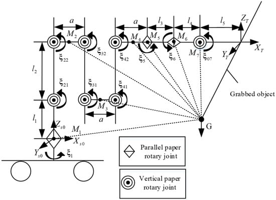
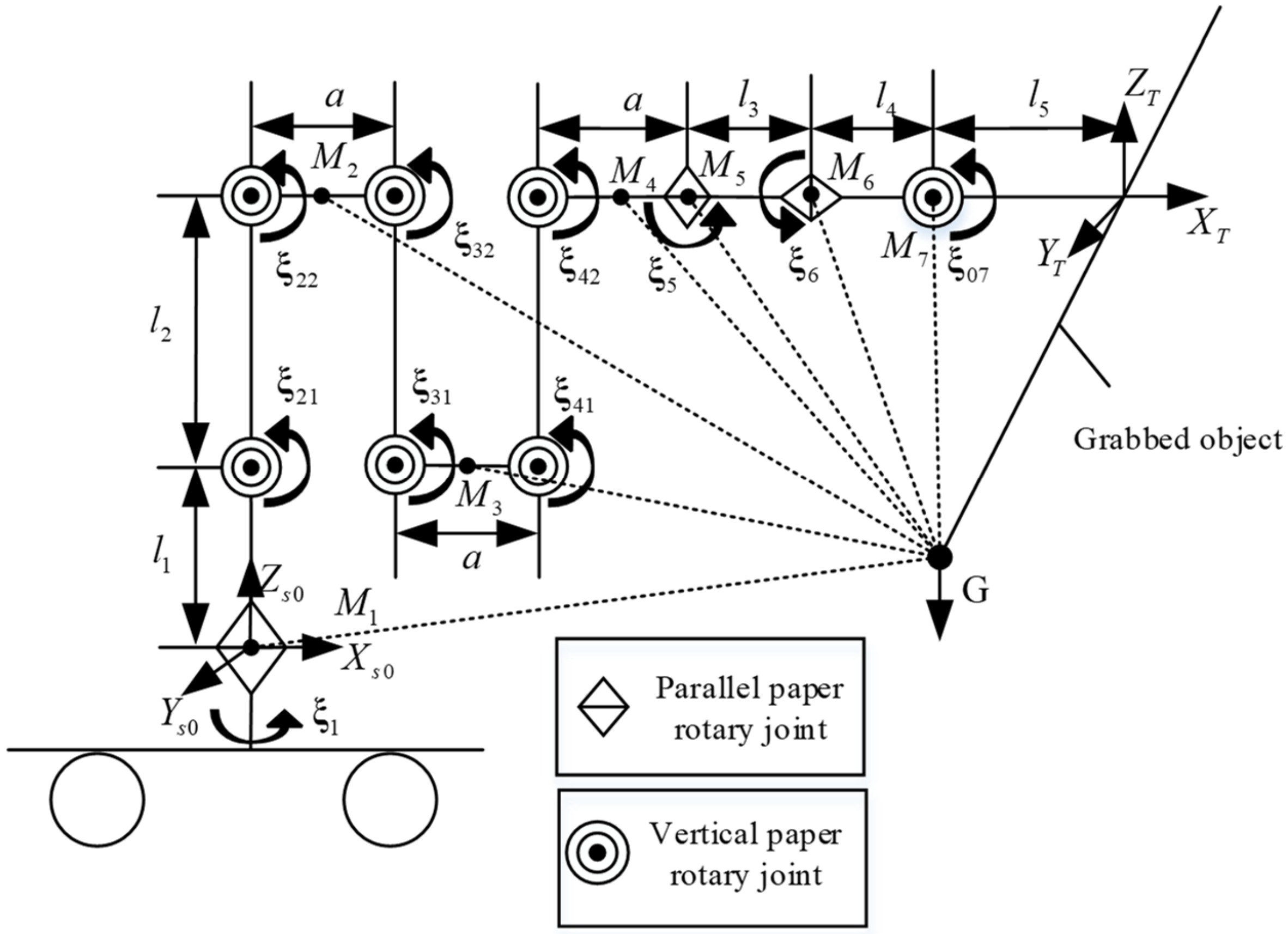
In Figure 9, a downward gravitational force G is applied at the center of the board, and the moment points Mi of the seven joints are defined. Because the manipulator assumes different poses at different grasping points, the distance between each moment point Mi and point G is determined for each pose, corresponding to the length of the dashed line shown in the figure. In the figure, joints and are reciprocal, and together they determine the position of the intermediate link between joints and . Here, M2 is defined at the midpoint between Joint and Joint , and the remaining moment points are determined in the same manner.
Figure 9.
A reference configuration diagram of the manipulator at different grasping positions.
The outward translation of the end-effector grasping position on the board can be regarded as a linear motion trajectory. The magnitude of the moment Mi is determined for different poses along the linear motion trajectory. In the solution process, inverse kinematics of the manipulator are first performed for different end-effector trajectories to obtain the angle of each joint. Subsequently, the positions of M1~M7 are determined, while the position of G is known and remains unchanged. Finally, the moments at M1~M7 are determined.
Calculate the distance of the torque:
In the above equation, denotes the coordinate vector of the gravity point G; denotes the first component of the matrix , and denotes the first component of the matrix ; the remaining components are defined in the same manner.
The torque of Joints 1–7 can be obtained as follows:
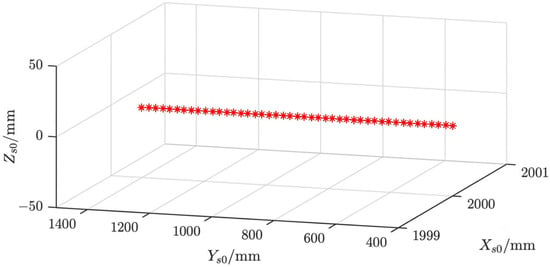
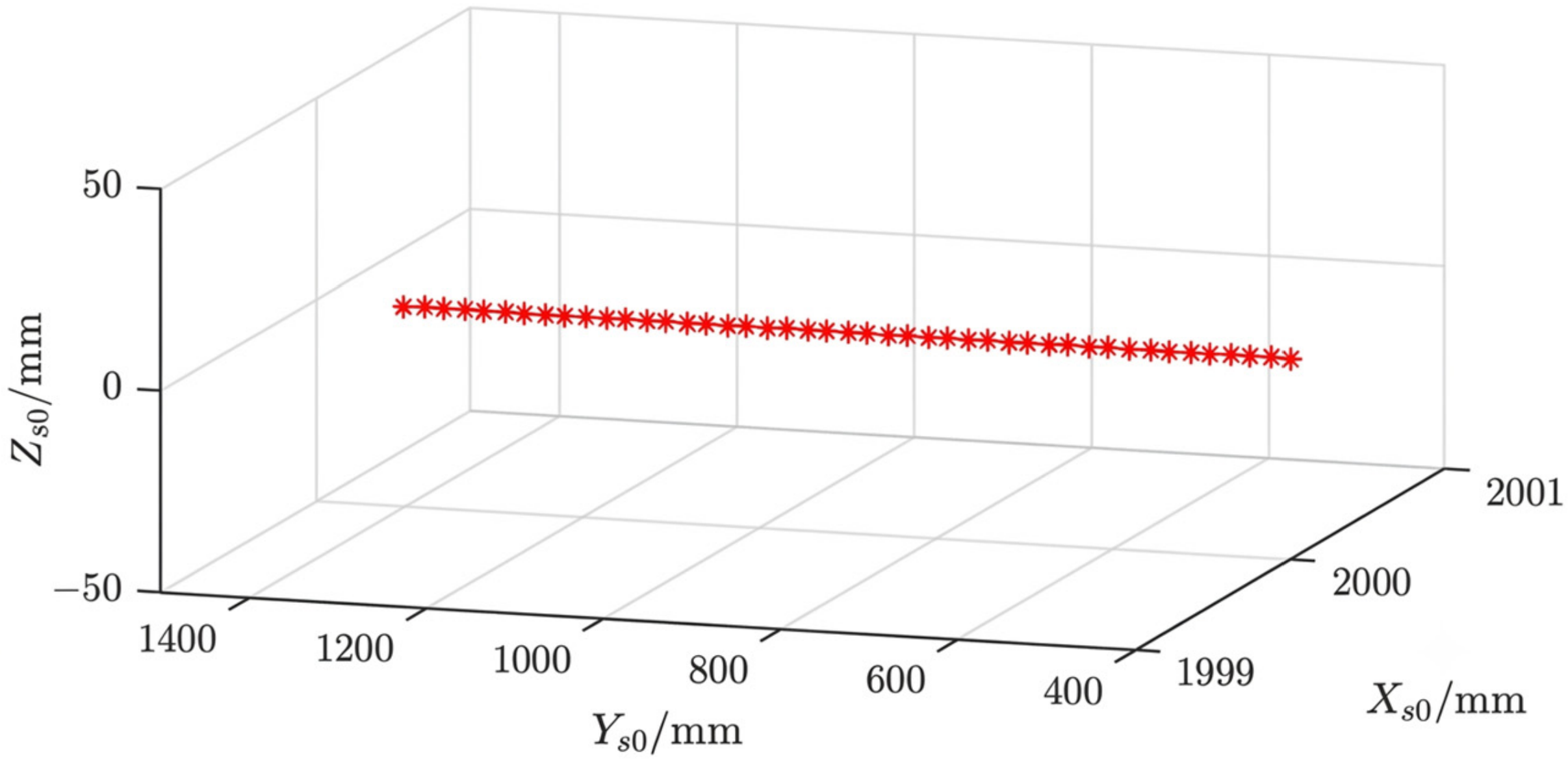
When the grasping point at the end of the two arms changes, the grasping distance of the two arms increases continuously. The translation of the grasping position on the board can be equivalently represented as a linear motion trajectory of the end-effector along the y-axis of the base coordinate system under a fixed load, as shown in Figure 10. The trajectory in the figure is based on the coordinate system of the robot. This trajectory is a straight line with y ranging from 0 mm to 1500 mm, where x = 2000 mm and z = 0 mm. In this situation, the moments at Mi are determined, while the end load at point G is set to 3500 N.
Figure 10.
Straight line movement trajectory.
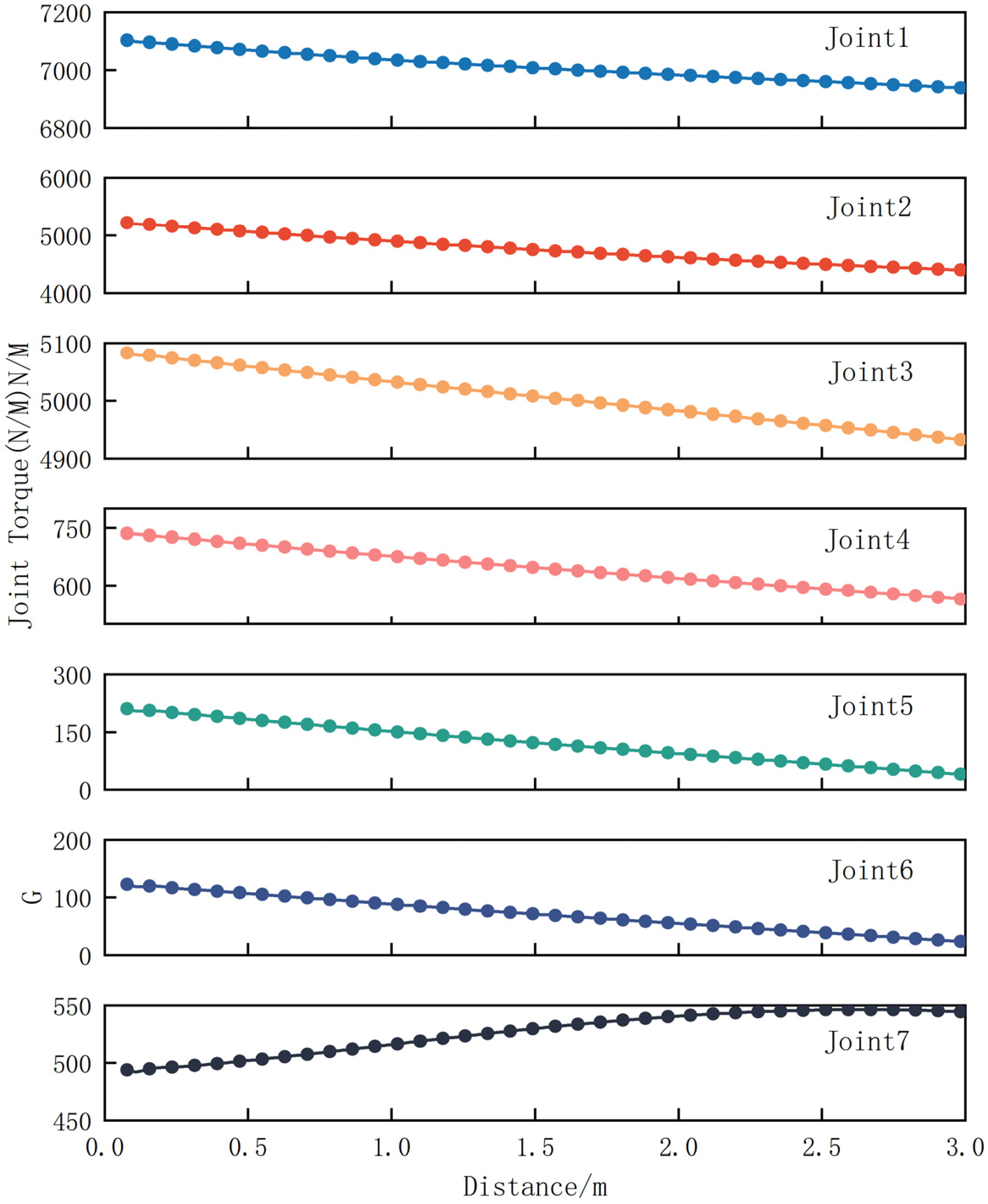
Mechanical simulations of each joint of the manipulator were conducted for every trajectory point shown in Figure 10, and the results are presented in Figure 11.
Figure 11.
The simulation results of each joint torque.
The above results indicate that as the relative distance between the two end-effectors increases, the torques of Joints 1–6 gradually decrease, the mechanism’s deformation decreases, the stiffness increases, and the mechanical performance shows a continuous improvement. Although the torque at Joint 7 shows an upward trend, it remains within the joint’s optimal load range. As the primary mechanical criterion for the robot, the end-effector moment index decisively influences the grasping strategy investigated in this study.
4.2. Finite Element Analysis of Different Grasping Points on the End-Effector
The above analysis indicates that the inter-end-effector grasping position distance is negatively monotonic with both torque and stiffness. However, in practice, stability is also a critical factor that warrants further investigation. In this section, finite element analysis is employed to investigate the vibration modes of the dual-arm end-effectors at different grasping positions.
Firstly, the finite element model is simplified by removing small geometric features such as chamfers, fillets, threaded holes, and non-load-bearing minor components. After defining the mesh size and related parameters in the Mesh module, automatic meshing is performed. The material is defined as Q355 steel, with an elastic modulus of 2.06 × 10¹¹ N/m2, a density of 7850 kg/m3, a shear modulus of 6.27 × 10¹⁰ N/m2, a tensile strength of 450 MPa, and a yield strength of 355 MPa. To simulate the force and constraint conditions of the robot under actual working conditions, Bonded and No Separation constraints are applied to the contact surfaces between joint interfaces to improve the accuracy of the simulation results.
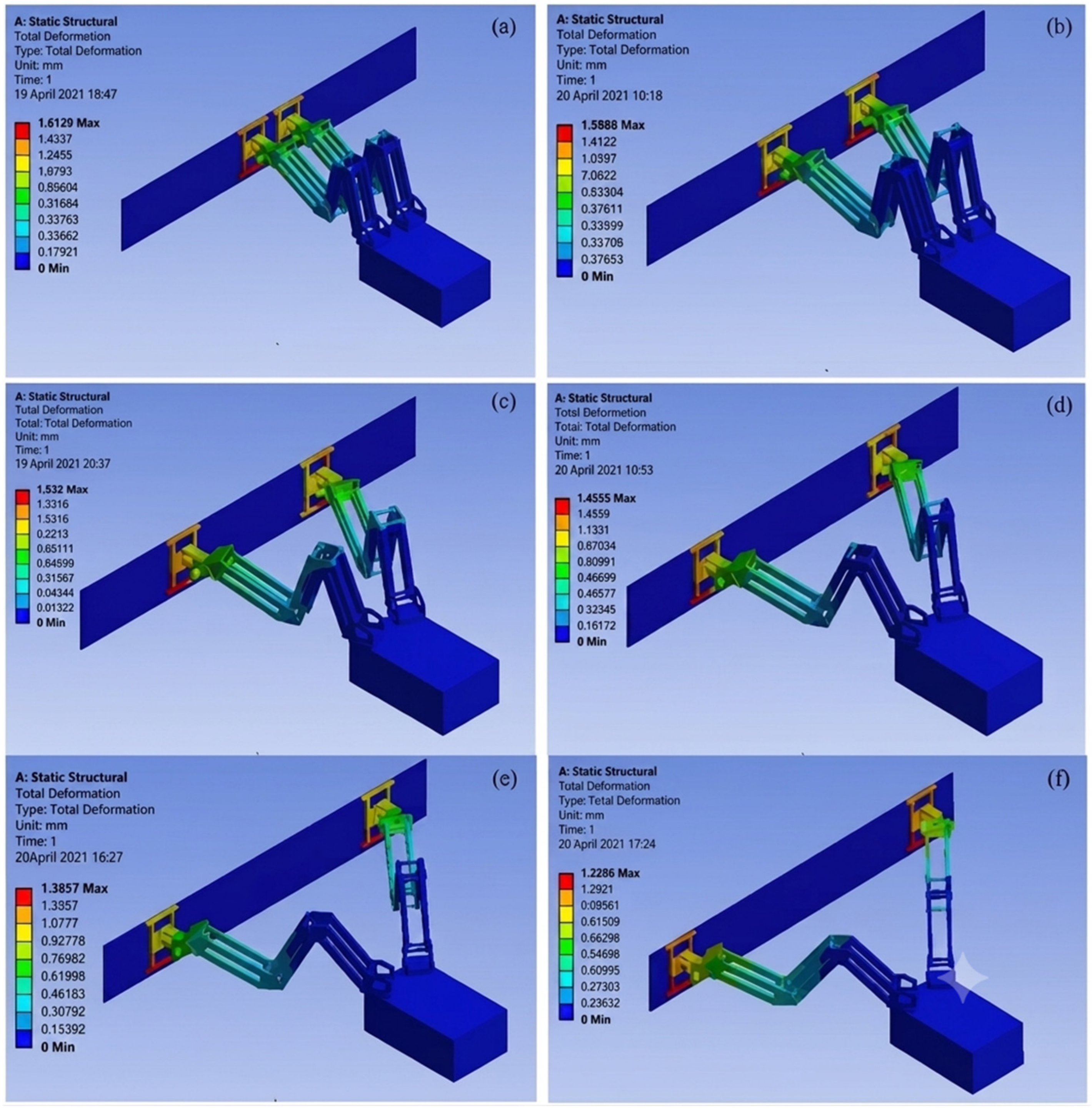
A force of 3500 N is applied at the center of the grasping plate. The static stiffness distributions under different grasping poses are obtained through simulation, as shown in Figure 12.
Figure 12.
Static stiffness under different grasping points: (a) 0 m; (b) 0.5 m; (c) 1 m; (d) 1.5 m; (e) 2 m; (f) 2.5 m.
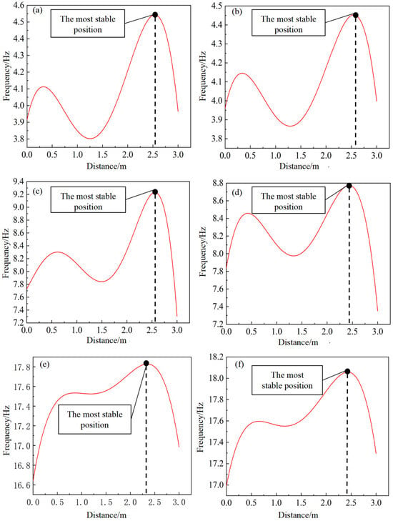
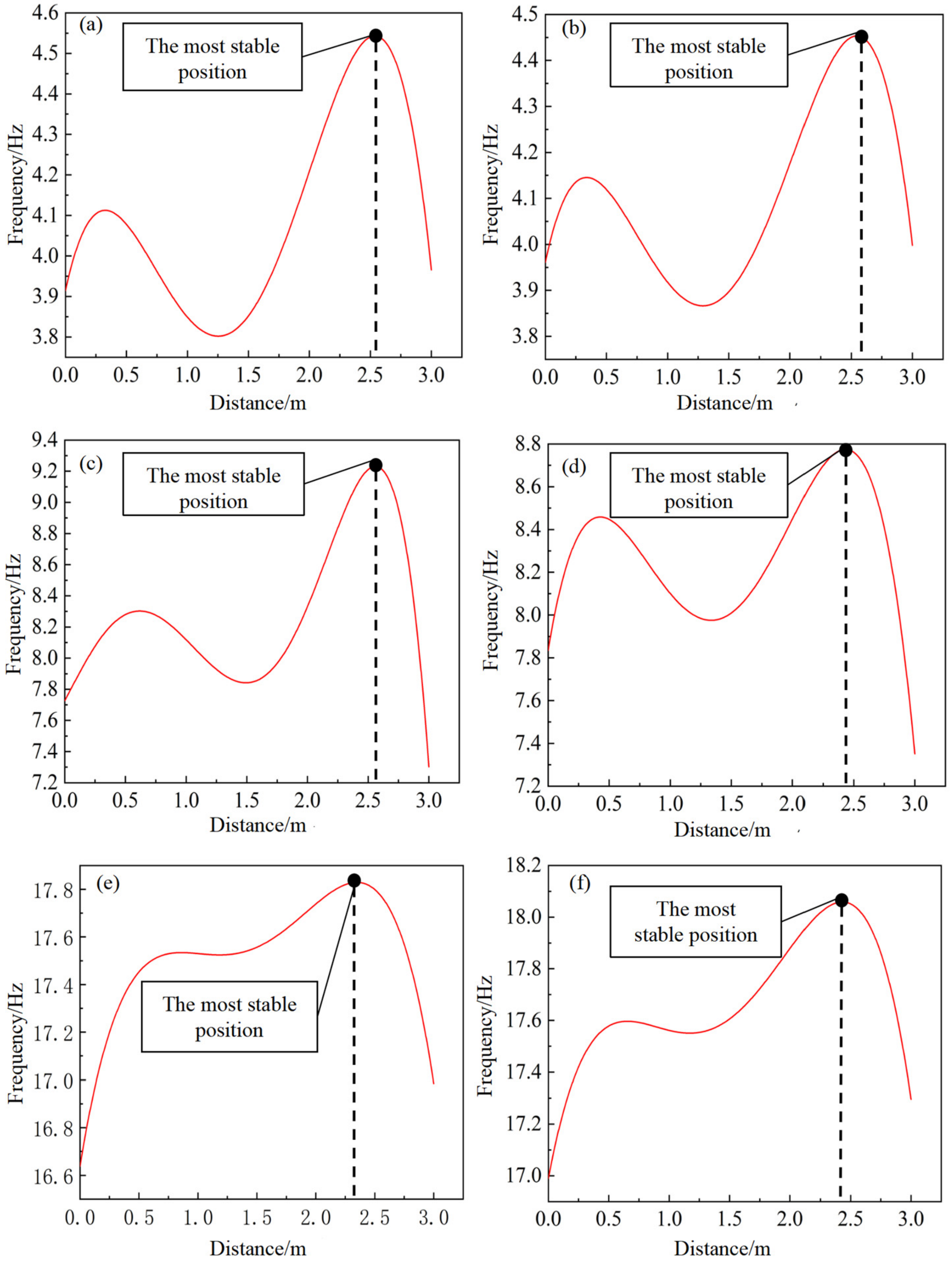
Finite element analysis was conducted to investigate the first through sixth-order vibration modes of the manipulators at different grasping positions. A gripping load of 3500 N was applied at the end-effector, and the corresponding vibration parameters were defined. Finite element models of the 7-DOF dual-arm robot with three parallelogram mechanisms were then established for different grasping positions. The simulation results are presented in Figure 13.
Figure 13.
The first- to sixth-order modes under different grasping points at different positions: (a) the first-order mode; (b) second-order mode; (c) third-order mode; (d) fourth-order mode; (e) fifth-order mode; (f) sixth-order mode.
The joint mechanical simulations and vibration modal analysis indicate that as the relative distance between the two end-effectors increases, the joint torques decrease, the stiffness increases, and the robot’s mechanical performance continues to improve. The vibration stability exhibits an optimal working range of 2.3–2.55 m.
The dual-arm plate installation robot is designed for large-sized, high-load plate assembly tasks. To meet the requirements of high-load operation, the mechanism design prioritizes mechanical performance. A peak stability region is observed within the range of 2.3–2.55 m in vibration stability analysis. In this interval, the distance between the dual-arm clamping points is relatively large, thereby significantly improving the robot’s structural stiffness. Meanwhile, the dexterity of the mechanism in this region still satisfies the operational requirements of plate installation tasks. Therefore, when the manipulator is extended to approximately 3.5 m, the range of 2.3–2.55 m is identified as the optimal grasping spacing. In addition, in this study, simulation results are referenced to the center points of the end-effectors of the dual-arm robot. However, in practice, the center-to-center distance between end-effectors cannot be measured accurately. Therefore, the boundary-to-boundary distance of the two end-effectors is adopted as the practical reference. In actual operation, the corresponding grasping range is 2–2.25 m, based on the end-effector boundary distance.
5. Experiment
To validate the engineering applicability and reliability of the proposed dual-arm grasping strategy, positioning repeatability experiments were conducted on a self-developed redundant dual-arm board installation robot prototype during collaborative manipulation of large- and medium-sized building boards.
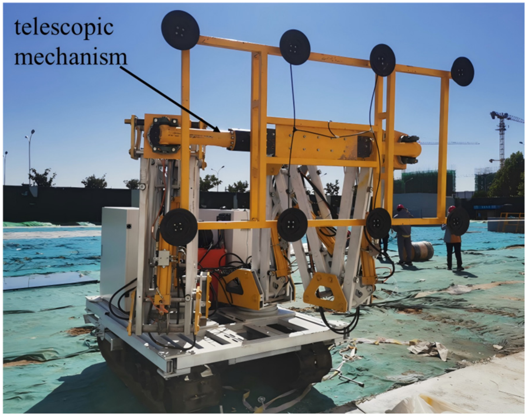
Furthermore, the building boards to be manipulated are generally large and heavy. Directly employing an end-effector designed for single-arm operation in dual-arm grasping applications can significantly degrade grasping stability. Meanwhile, the grasping strategy proposed in this study is designed with respect to the midpoint between the two end-effectors. Therefore, the original end-effector design cannot guarantee that the two end-effectors remain collinear during operation. To ensure experimental safety and achieve precise alignment of the dual-arm end-effectors, a dedicated end-effector was developed based on the optimal grasping strategy for collaborative dual-arm operations. As shown in Figure 14. The proposed end-effector incorporates a built-in telescopic mechanism, enabling dynamic adjustment of the distance between the centers of the two end-effectors.
Figure 14.
The dual-arm robot equipped with the proposed end-effector.
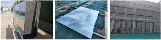
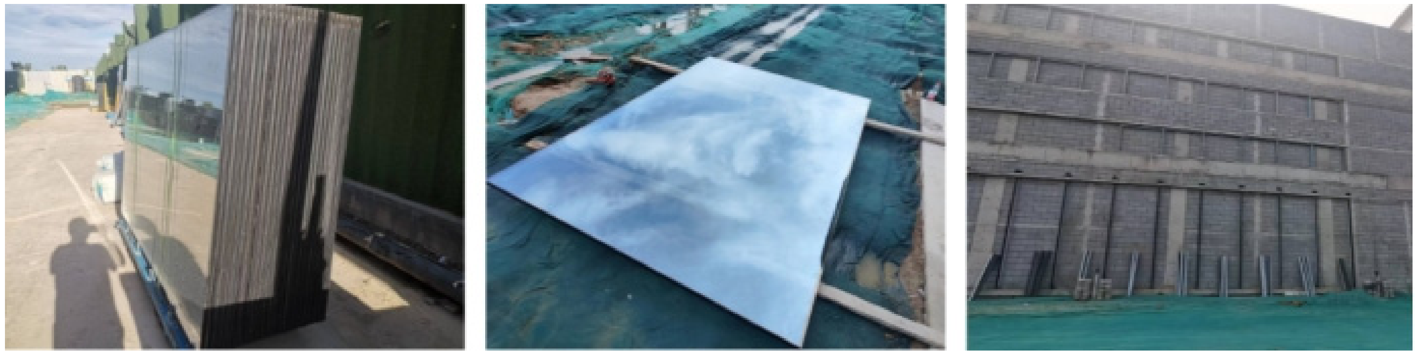
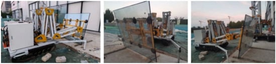
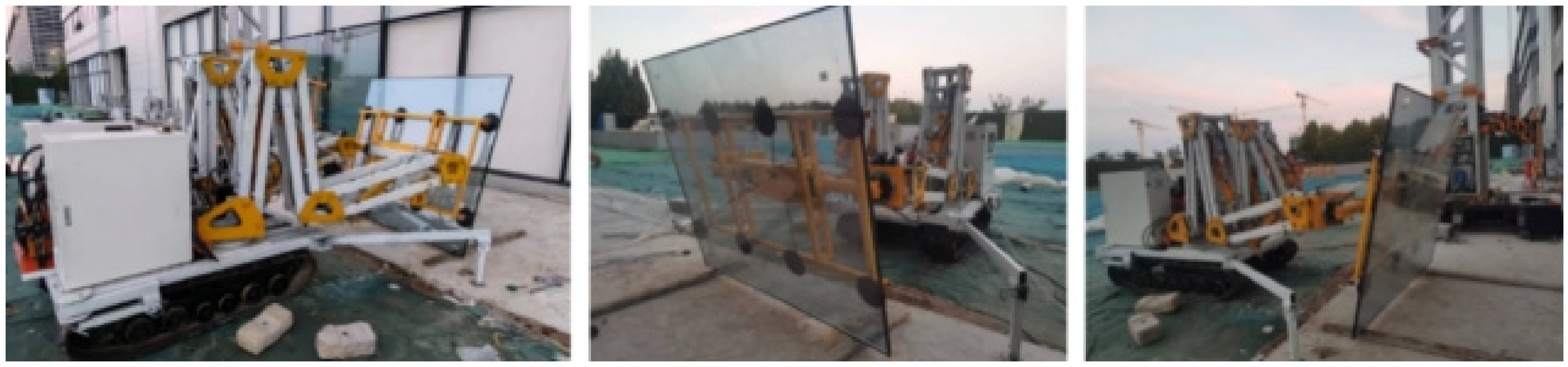
A 2 m × 3 m glass curtain wall board commonly used in building construction was selected as the test specimen for the positioning repeatability experiments. The board had a mass of 350 kg. Its weight and dimensions aligned with the installation conditions for large- and medium-sized boards, realistically reflecting actual construction loads and operational requirements. Figure 15 illustrates the experimental board and the test environment.
Figure 15.
The experimental board and test environment.
Positioning repeatability is defined as the ability of a robot end-effector to repeatedly reach the same spatial position under identical operating conditions and is widely regarded as a key indicator of robot performance. For the positioning repeatability experiment under loaded conditions, the center point between the two end-effectors was first adjusted to the optimal grasping position determined by the proposed grasping strategy, yielding a center-to-center distance of 2.3 m. As shown in Figure 16. The vacuum gripper was then activated to securely grasp the glass curtain wall board.
Figure 16.
The dual-arm cooperative operation mode.
To evaluate the positioning repeatability of the board installation parallel robot, three measurement points were selected within the robot workspace. The coordinates of the measurement points W1, W2, and W3 are listed in Table 3.
Table 3.
Measuring point coordinates.
To conduct the repeatability experiment, the motion trajectory of the manipulator was planned in advance. A laser tracker was used to monitor the motion trajectory in real time, and the spatial coordinates of the initial point and three measurement points were collected. The repeat positioning accuracy was calculated using the measured data for the target points W1, W2, and W3, and the results are presented in Table 4.
Table 4.
Measurement point coordinates.
The results show that, when the dual-arm grasping strategy proposed in this study is used to conduct the repeat positioning accuracy experiment, the maximum positioning error of the robot under load conditions is 0.593 mm, which is within the design requirement of ±1 mm. This confirms that the proposed grasping strategy meets the robot’s operational performance requirements. Furthermore, the experimental results demonstrate that the proposed optimal end-effector grasping strategy for the dual-arm system is effective and feasible. It significantly improves the cooperative performance of the dual-arm plate installation robot and provides reliable technical support for the automated installation of large- and medium-scale building boards.
6. Conclusions
To address the issue that end-effector grasping positions significantly affect the overall operational performance of dual-arm building board installation robots during cooperative operations, this study employed a self-developed 7-DOF redundant dual-arm building board installation robot as the experimental platform and systematically investigated the optimal dual-arm end-effector grasping strategy based on the optimization principle of prioritizing static performance while considering dexterity.
In this study, the symmetric dual-arm system was simplified into a model consisting of a single manipulator connected to a central spherical-joint mechanism, and a kinematic model of the manipulator and the spherical-joint linkage was established. Based on the service sphere in the dexterity index, the dexterity envelope surfaces corresponding to different grasping distances were derived, confirming a negative linear correlation between the end-effector grasping distance and dexterity. Subsequently, the variation in grasping-point spacing was equivalently transformed into the linear trajectory of the end load, the joint torques were calculated, and mechanical simulations were performed based on the force transmission characteristics of rigid-body mechanics. Finite element analysis was further conducted for the first time through sixth-order vibration modes. Considering joint torques, stiffness, vibration stability, and dexterity constraints comprehensively, the optimal relative grasping distance between the two end-effectors was determined to be 2.3–2.55 m when the manipulator was extended to approximately 3.5 m. Finally, prototype grasping experiments were conducted to validate the proposed strategy. The results show that under load conditions, the maximum repeat positioning error is 0.593 mm, enabling accurate achievement of the target pose and meeting the robot’s performance requirements. The experimental results demonstrate that the proposed dual-arm grasping strategy is effective, reliable, and suitable for practical engineering applications.
Future research will further investigate the influence of the robot-to-plate distance and the redundant actuation configuration on system performance. In addition, dynamic trajectory planning will be incorporated to optimize the stability of cooperative grasping, thereby improving operational accuracy and reliability under complex working conditions. Meanwhile, the robot’s overall workspace and the dexterous workspace of the end-effector will be analyzed. The reachable position range and allowable orientation range of the end-effector will be quantified to clearly define the mechanism’s operational boundaries in complex construction scenarios.
Author Contributions
Conceptualization, Z.M., Y.L. (Yuxin Liu) and Y.L. (Yongbin Li); methodology, Z.M., Y.L. (Yuxin Liu), Y.L. (Yongbin Li) and T.L.; software, Z.M., Z.N. and Z.K.; validation, Z.M., Y.L. (Yuxin Liu) and Y.L. (Yongbin Li); formal analysis, Z.N. and Z.K.; investigation, Z.M., Y.L. (Yuxin Liu) and Y.L. (Yongbin Li); resources, Y.L. (Yuxin Liu) and Y.L. (Yongbin Li); data curation, Z.M.; writing—original draft preparation, Z.M.; writing—review and editing, Z.M.; supervision, T.W.; project administration, Z.L. All authors have read and agreed to the published version of the manuscript.
Funding
The work presented in this paper was supported by the Integrated Project of the Regional Innovation and Development Joint Fund of the National Natural Science Foundation of China (No. U24A6005), the Central Guidance Fund for Local Science and Technology Development from Hebei Provincial Department of science and technology (No. 246Z1907G), the Science Research Project of the Hebei Education Department (No. JZX2024014), the Key R&D and SME Innovation Program of Shijiazhuang from Shijiazhuang Municipal Bureau of science and technology (No. 2512301901A), the Hebei Natural Science Foundation (No. E2025208064), and the Key R&D Special Project Funded for Hebei-Based Universities in Shijiazhuang from Shijiazhuang Municipal Bureau of science and technology (No. 51174112).
Data Availability Statement
The data supporting the findings of this study are available within the article. For further information, please contact the corresponding authors.
Acknowledgments
The authors would like to express their sincere gratitude to the anonymous reviewers and editors for their valuable comments and suggestions on this paper.
Conflicts of Interest
The authors Yuxin Liu and Yongbin Li were employed by the Hebei Construction Engineering Group Co., Ltd. The authors Zedan Li and Tong Wang were employed by the Hebei Construction Engineering Group Building Decoration Engineering Co., Ltd. The relevant authors are merely employed by the above companies, and there are no conflicts of interest. The remaining authors declare that the research was conducted in the absence of any commercial or financial relationships that could be construed as a potential conflict of interest.
References
- Mika, P.; Temirkhan, T.; Leila, Z. Classification of precast concrete façade elements used in contemporary residential buildings. Sr. Mieszk. Hous. Environ. 2023, 45, 33–37. [Google Scholar] [CrossRef] [Scilit]
- Luo, X.; Zheng, X.; Liao, C.; Xiao, Y.; Deng, C.; Liu, S.; Chen, Q. Research on the modular design method and application of prefabricated residential buildings. Buildings 2024, 14, 3014. [Google Scholar] [CrossRef] [Scilit]
- Antwi-Afari, M.F.; Li, H.; Edwards, D.J.; Pärn, E.A.; Seo, J.; Wong, A.Y.L. Biomechanical analysis of risk factors for work-related musculoskeletal disorders during repetitive lifting task in construction workers. Autom. Constr. 2017, 83, 41–47. [Google Scholar] [CrossRef] [Scilit]
- Bogue, R. What are the prospects for robots in the construction industry? Ind. Robot 2018, 45, 1–6. [Google Scholar] [CrossRef] [Scilit]
- Xiao, B.; Chen, C.; Yin, X. Recent advancements of robotics in construction. Autom. Constr. 2022, 144, 104591. [Google Scholar] [CrossRef] [Scilit]
- Li, S.; Zhou, X.; Cheng, G.; Teng, W.; Zeng, Y.; Wei, G.; Chen, Y. A scheme of installing ALC wall panels based on autonomous mobile robot. J. Build. Eng. 2024, 94, 109991. [Google Scholar] [CrossRef] [Scilit]
- Yang, D.; Li, Y.; Li, T.; Zhang, T.; Han, M.; Yan, H. The system design of external cladding installation robot. Int. J. Adv. Robot. Syst. 2020, 17, 1729881420969062. [Google Scholar] [CrossRef] [Scilit]
- Kim, R.; Balakirsky, S.B.; Ahlin, K.J.; Marcum, M.; Mazumdar, A. Enhancing payload capacity with dual-arm manipulation and adaptable mechanical intelligence. J. Mech. Robot. 2021, 13, 021012. [Google Scholar] [CrossRef] [Scilit]
- Peta, K.; Wiśniewski, M.; Kotarski, M.; Ciszak, O. Comparison of single-arm and dual-arm collaborative robots in precision assembly. Appl. Sci. 2025, 15, 2976. [Google Scholar] [CrossRef] [Scilit]
- Wang, H.; Li, R.; Gao, Y.; Cao, C.; Ge, L. Comparative study on the redundancy of mobile single- and dual-arm robots. Int. J. Adv. Robot. Syst. 2016, 13, 1729881416666782. [Google Scholar] [CrossRef] [Scilit]
- Ren, Y.; Zhou, Z.; Xu, Z.; Yang, Y.; Zhai, G.; Leibold, M.; Ni, F.; Zhang, Z.; Buss, M.; Zheng, Y. Enabling versatility and dexterity of the dual-arm manipulators: A general framework toward universal cooperative manipulation. IEEE Trans. Robot. 2024, 40, 2024–2045. [Google Scholar] [CrossRef] [Scilit]
- Wang, J.; Zhang, T.; Wang, Y.; Luo, D. A novel learning-based approach for dual-arm robot operation point selection. In Proceedings of the 2023 IEEE International Conference on Development and Learning (ICDL), Macau, China, 9–11 November 2023; IEEE: Piscataway, NJ, USA, 2023; pp. 492–499. [Google Scholar] [CrossRef] [Scilit]
- Culleton, M.; McGinn, C.; Kelly, K. Framework for assessing robotic dexterity within flexible manufacturing. J. Intell. Robot. Syst. 2017, 87, 507–529. [Google Scholar] [CrossRef] [Scilit]
- Vinogradov, I.B.; Kobrinskiy, A.Y.; Stepanenko, Y.A.; Tyves, L.I. Features of the Kinematics of Manipulators and Volumes Methods; Mechanics of Machines, No. 27/28; NASA-TT-F-14336; NASA: Washington, DC, USA, 1973; pp. 4–19. [Google Scholar]
- Gao, G.; Liu, C.; Wang, H. Kinematic accuracy of picking robot constructed by wire-driven continuum structure. Proc. Inst. Mech. Eng. Part E J. Process Mech. Eng. 2021, 235, 299–311. [Google Scholar] [CrossRef] [Scilit]
- Léon, J.-C.; Dupeux, T.; Chardonnet, J.-R.; Perret, J. Dexterous grasping tasks generated with an add-on end effector of a haptic feedback system. J. Comput. Inf. Sci. Eng. 2016, 16, 030903. [Google Scholar] [CrossRef] [Scilit]
- Xu, R.; Luo, J.; Wang, M. Optimal grasping pose for dual-arm space robot cooperative manipulation based on global manipulability. Acta Astronaut. 2021, 183, 300–309. [Google Scholar] [CrossRef] [Scilit]
- Mira, D.; Delgado, A.; Mateo, C.M.; Puente, S.T.; Candelas, F.A. Study of dexterous robotic grasping for deformable objects manipulation. In Proceedings of the 2015 IEEE Industrial Electronics Society Conference on Control & Automation, Kathmandu, Nepal, 21–23 December 2015; pp. 262–266. [Google Scholar]
- Gosselin, C.; Laliberté, T.; Veillette, A. Singularity-free kinematically redundant planar parallel mechanisms with unlimited rotational capability. IEEE Trans. Robot. 2015, 31, 457–467. [Google Scholar] [CrossRef] [Scilit]
- Guo, W.; Li, R.; Cao, C.; Gao, Y. A novel method of dexterity analysis for a 5-DOF manipulator. J. Robot. 2016, 2016, 8901820. [Google Scholar] [CrossRef] [Scilit]
- Hu, H.; Cao, J.; Cao, Y. Prescribed time tracking control without velocity measurement for dual-arm robots. Inf. Sci. 2023, 629, 533–550. [Google Scholar] [CrossRef] [Scilit]
- Liu, X.-J.; Wu, C.; Wang, J. A new approach for singularity analysis and closeness measurement to singularities of parallel manipulators. J. Mech. Robot. 2012, 4, 041001. [Google Scholar] [CrossRef] [Scilit]
- Liu, H.; Huang, T.; Kecskeméthy, A.; Chetwynd, D.G. A generalized approach for computing the transmission index of parallel mechanisms. Mech. Mach. Theory 2014, 74, 245–256. [Google Scholar] [CrossRef] [Scilit]
- Pei, J.-F.; Cheng, J.-S. Optimization of force directional manipulability of dexterous robot hand. In Proceedings of the 2010 International Conference on System Science, Engineering Design and Manufacturing Informatization (ICSEM), Yichang, China, 12–14 November 2010; IEEE: Piscataway, NJ, USA, 2010; Volume 1, pp. 226–229. [Google Scholar] [CrossRef] [Scilit]
- Peng, S.; Cheng, Z.; Che, L.; Zheng, Y.; Cao, S. Kinematic performance analysis of a parallel mechanism for loading test of hydraulic support. Mech. Mach. Theory 2022, 168, 104592. [Google Scholar] [CrossRef] [Scilit]
- Nouri Rahmat Abadi, B.; Carretero, J.A. Modeling and real-time motion planning of a class of kinematically redundant parallel mechanisms with reconfigurable platform. J. Mech. Robot. 2023, 15, 021004. [Google Scholar] [CrossRef] [Scilit]

Disclaimer/Publisher’s Note: The statements, opinions and data contained in all publications are solely those of the individual author(s) and contributor(s) and not of MDPI and/or the editor(s). MDPI and/or the editor(s) disclaim responsibility for any injury to people or property resulting from any ideas, methods, instructions or products referred to in the content. |
© 2026 by the authors. Licensee MDPI, Basel, Switzerland. This article is an open access article distributed under the terms and conditions of the Creative Commons Attribution (CC BY) license.