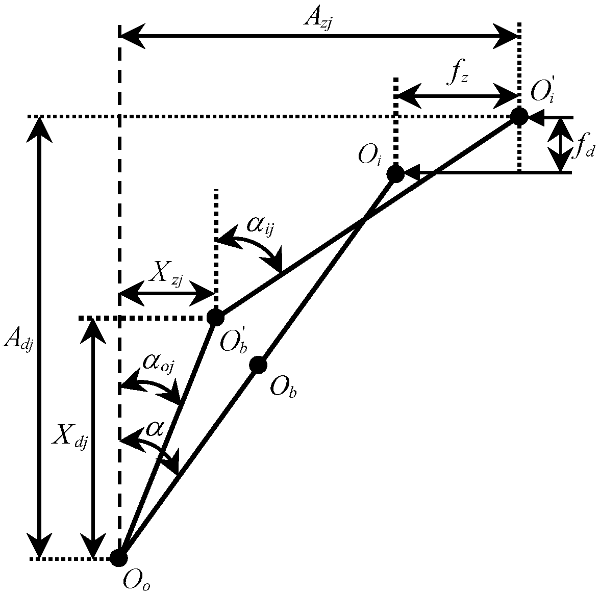
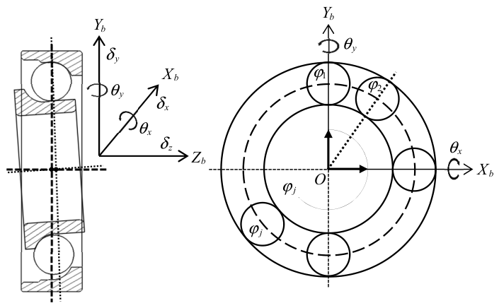
Figure 1.
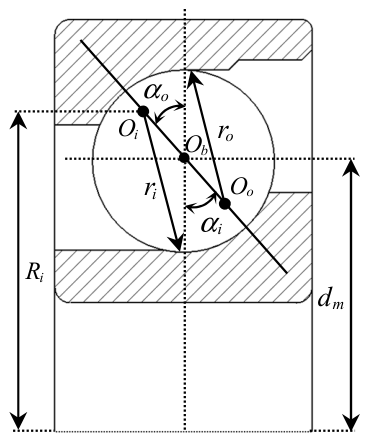
Angular contact ball bearing geometry.
Figure 1.
Angular contact ball bearing geometry.
Figure 2.
Radial and axial views of the bearing.
Figure 2.
Radial and axial views of the bearing.
Figure 3.
The relationship between ball and raceway.
Figure 3.
The relationship between ball and raceway.
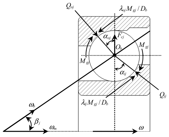
Figure 4.
Force analysis of the ball.
Figure 4.
Force analysis of the ball.
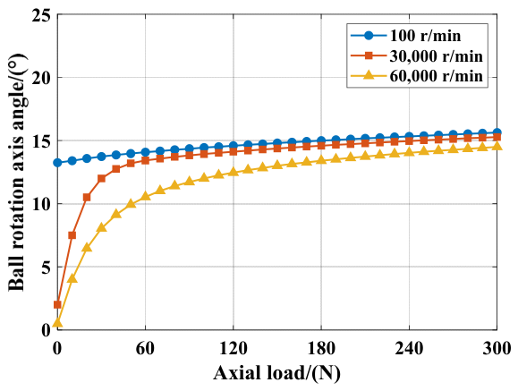
Figure 5.
Numerical calculation of β under low-speed and high-speed conditions.
Figure 5.
Numerical calculation of β under low-speed and high-speed conditions.
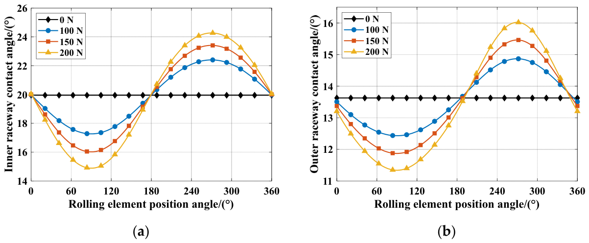
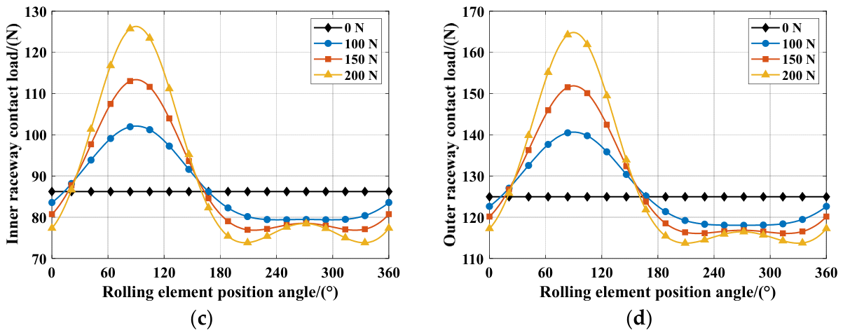
Figure 6.
Effect of radial force on the contact angle and contact load. (a) Variation of inner raceway contact Angle with load; (b) Variation of outer raceway contact Angle with load; (c) Variation of inner raceway contact load with load; (d) Variation of outer raceway contact load with load.
Figure 6.
Effect of radial force on the contact angle and contact load. (a) Variation of inner raceway contact Angle with load; (b) Variation of outer raceway contact Angle with load; (c) Variation of inner raceway contact load with load; (d) Variation of outer raceway contact load with load.
Figure 7.
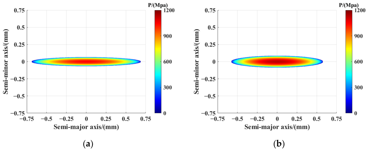
Compressive stress distribution on the inner and outer raceway contact ellipses. (a) Stress distribution on the inner contact ellipse; (b) Stress distribution on the outer contact ellipse.
Figure 7.
Compressive stress distribution on the inner and outer raceway contact ellipses. (a) Stress distribution on the inner contact ellipse; (b) Stress distribution on the outer contact ellipse.
Figure 8.
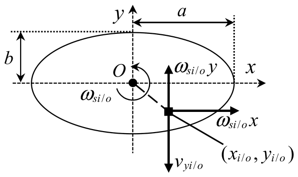
Sliding velocity distribution on contact ellipse.
Figure 8.
Sliding velocity distribution on contact ellipse.
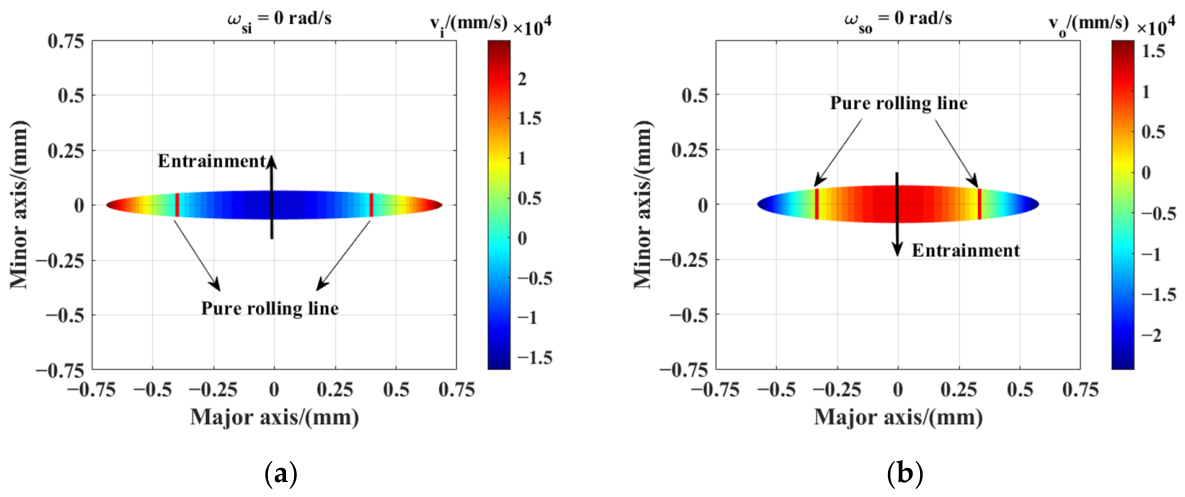
Figure 9.
Sliding velocity distribution without spin. (a) Inner raceway contact ellipse sliding velocity distribution; (b) Outer raceway contact ellipse sliding velocity distribution.
Figure 9.
Sliding velocity distribution without spin. (a) Inner raceway contact ellipse sliding velocity distribution; (b) Outer raceway contact ellipse sliding velocity distribution.
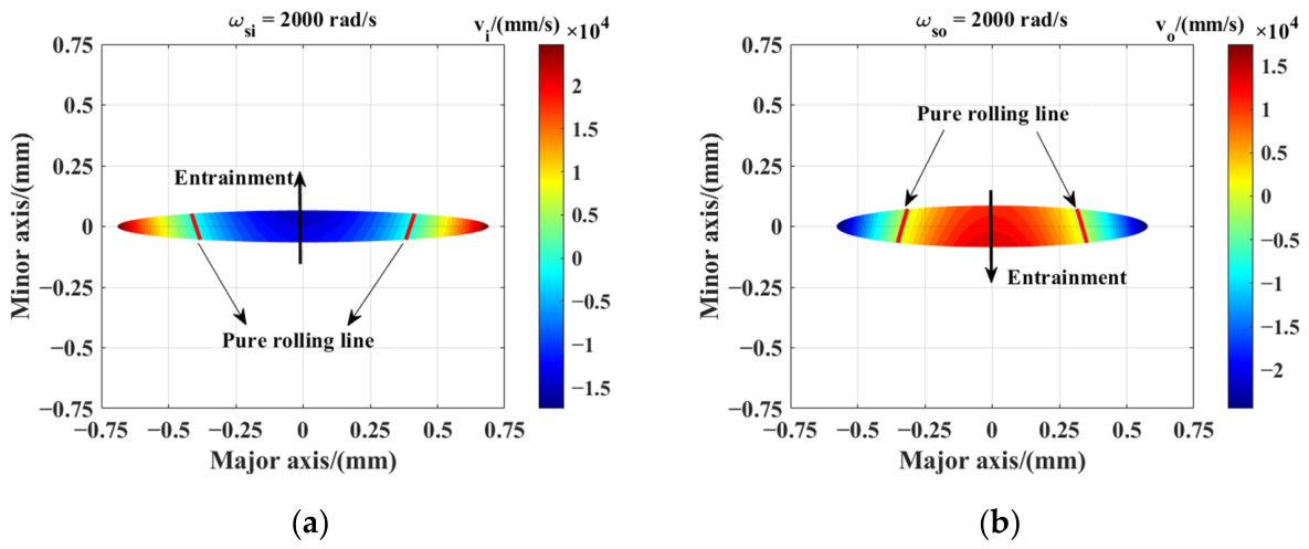
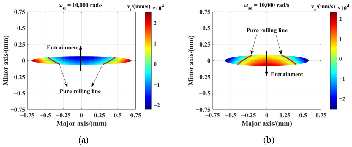
Figure 10.
Sliding velocity distribution at a spin speed of 2000 rad/s. (a) Inner raceway contact ellipse sliding velocity distribution; (b) Outer raceway contact ellipse sliding velocity distribution.
Figure 10.
Sliding velocity distribution at a spin speed of 2000 rad/s. (a) Inner raceway contact ellipse sliding velocity distribution; (b) Outer raceway contact ellipse sliding velocity distribution.
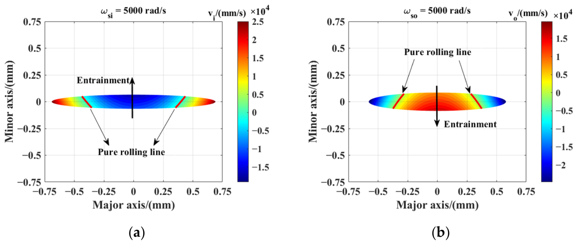
Figure 11.
Sliding velocity distribution at a spin speed of 5000 rad/s. (a) Inner raceway contact ellipse sliding velocity distribution; (b) Outer raceway contact ellipse sliding velocity distribution.
Figure 11.
Sliding velocity distribution at a spin speed of 5000 rad/s. (a) Inner raceway contact ellipse sliding velocity distribution; (b) Outer raceway contact ellipse sliding velocity distribution.
Figure 12.
Sliding velocity distribution at a spin speed of 10,000 rad/s. (a) Inner raceway contact ellipse sliding velocity distribution; (b) Outer raceway contact ellipse sliding velocity distribution.
Figure 12.
Sliding velocity distribution at a spin speed of 10,000 rad/s. (a) Inner raceway contact ellipse sliding velocity distribution; (b) Outer raceway contact ellipse sliding velocity distribution.
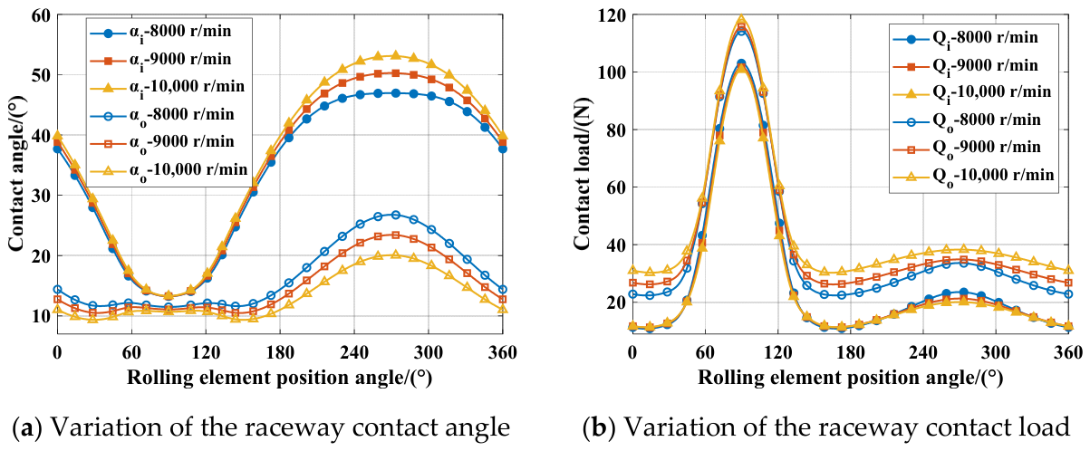
Figure 13.
Contact angles and contact loads of the inner and outer raceways.
Figure 13.
Contact angles and contact loads of the inner and outer raceways.
Figure 14.
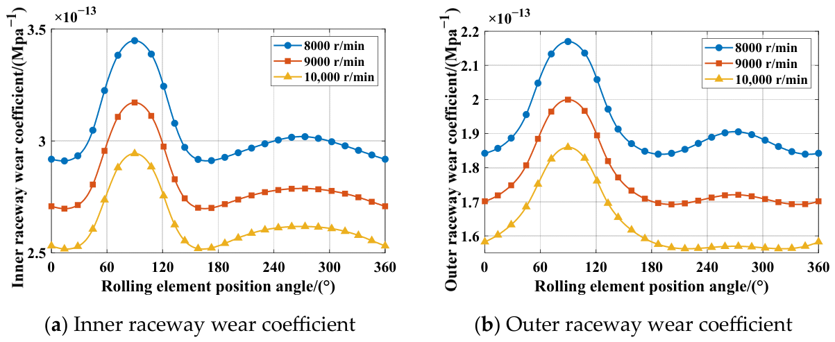
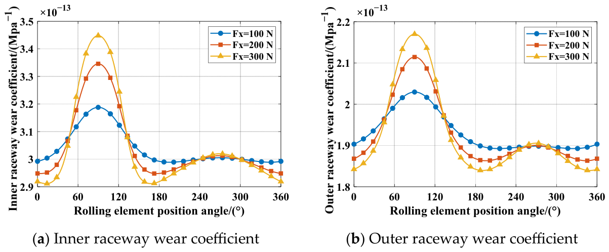
Effect of rotational speed on the wear coefficient of the inner and outer raceways.
Figure 14.
Effect of rotational speed on the wear coefficient of the inner and outer raceways.
Figure 15.
Contact angles and contact loads of the inner and outer raceways.
Figure 15.
Contact angles and contact loads of the inner and outer raceways.
Figure 16.
Effect of load on the wear coefficient of the inner and outer raceways.
Figure 16.
Effect of load on the wear coefficient of the inner and outer raceways.
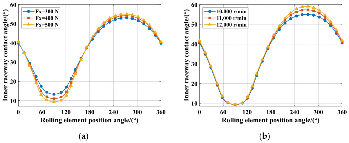
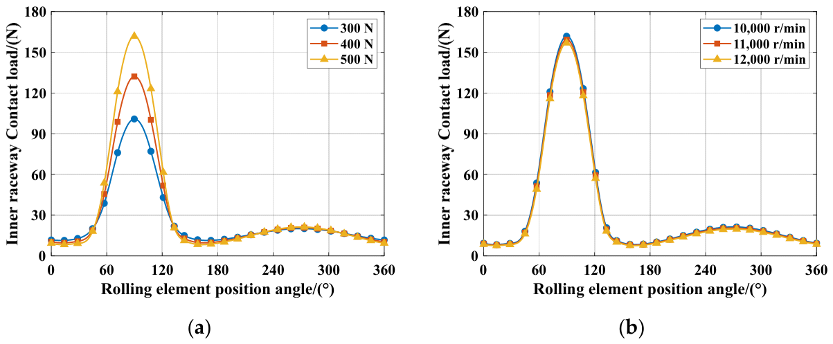
Figure 17.
Contact angles of the inner raceways. (a) Variation of inner contact angle with load; (b) Variation of inner contact angle with rotational speed.
Figure 17.
Contact angles of the inner raceways. (a) Variation of inner contact angle with load; (b) Variation of inner contact angle with rotational speed.
Figure 18.
Contact loads of the inner raceway. (a) Variation of inner contact load with load; (b) Variation of inner contact load with rotational speed.
Figure 18.
Contact loads of the inner raceway. (a) Variation of inner contact load with load; (b) Variation of inner contact load with rotational speed.
Figure 19.
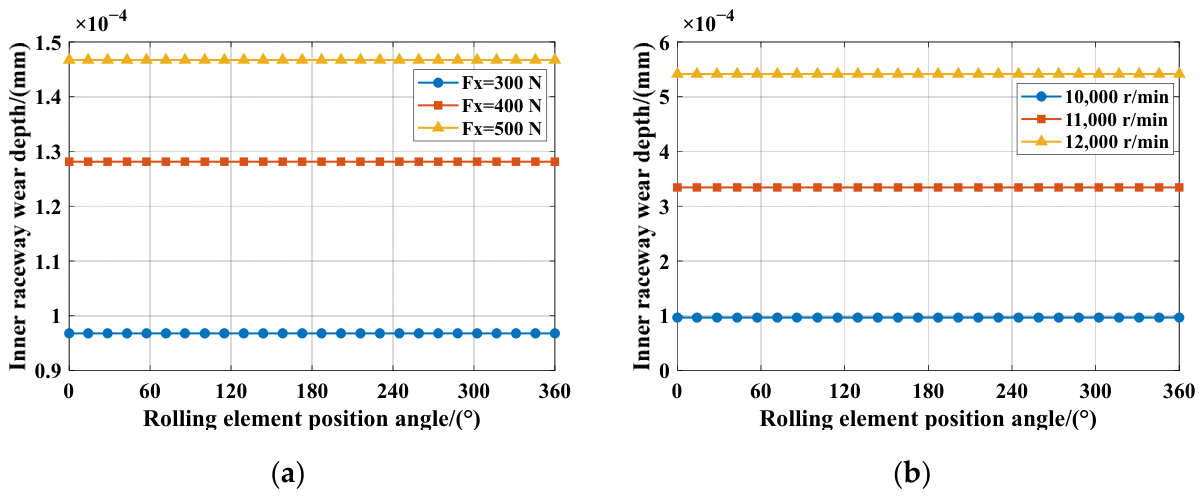
Effects of load and rotational speed on the inner raceway wear depth. (a) Variation of inner raceway wear depth with load; (b) Variation of inner raceway wear depth with rotational speed.
Figure 19.
Effects of load and rotational speed on the inner raceway wear depth. (a) Variation of inner raceway wear depth with load; (b) Variation of inner raceway wear depth with rotational speed.
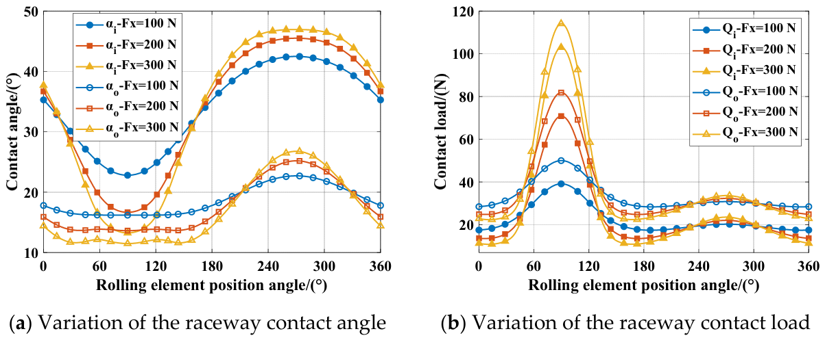
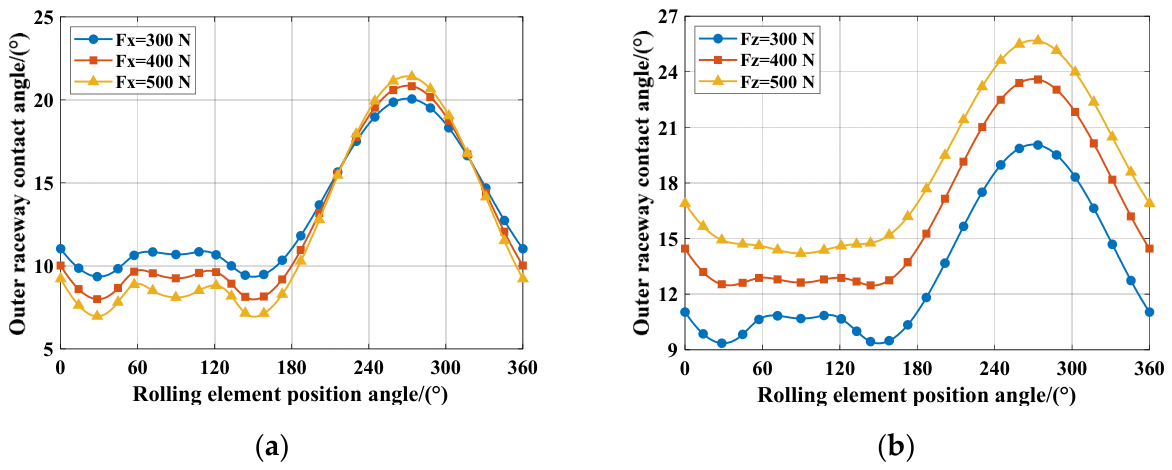
Figure 20.
Contact angles of the outer raceway. (a) Variation of outer contact angle with radial load; (b) Variation of outer contact angle with axial load.
Figure 20.
Contact angles of the outer raceway. (a) Variation of outer contact angle with radial load; (b) Variation of outer contact angle with axial load.
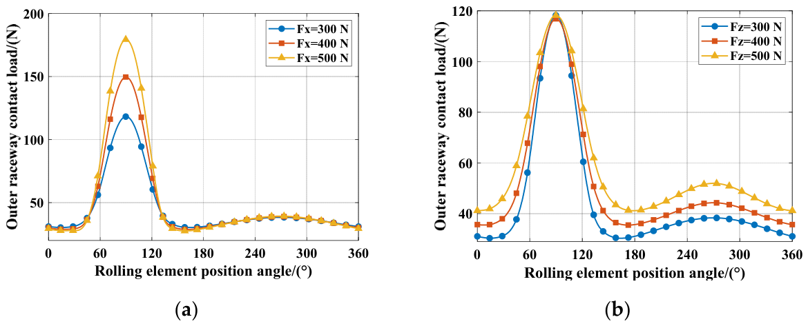
Figure 21.
Contact loads of the outer raceways. (a) Variation of outer contact load with radial load; (b) Variation of outer contact load with axial load.
Figure 21.
Contact loads of the outer raceways. (a) Variation of outer contact load with radial load; (b) Variation of outer contact load with axial load.
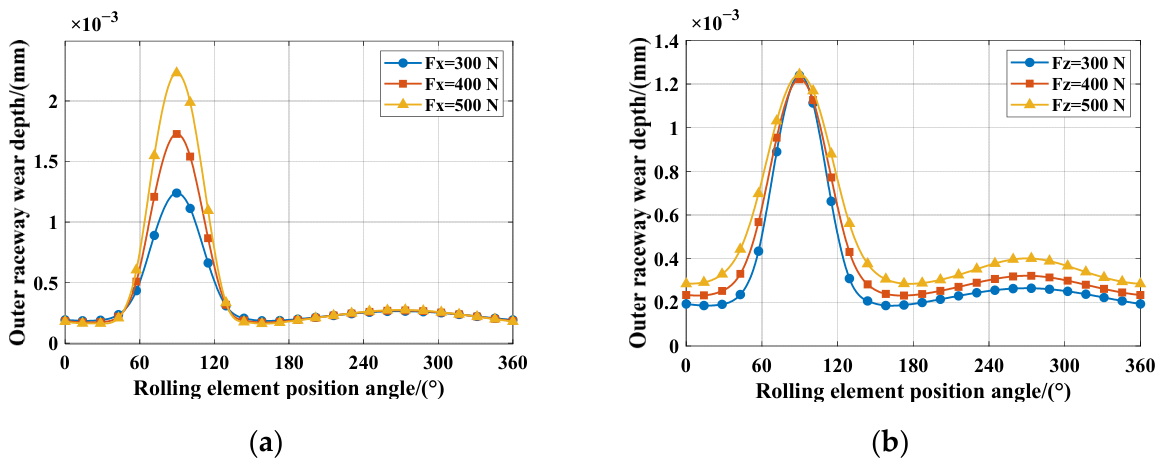
Figure 22.
Effect of load on the outer raceway wear depth. (a) Variation of outer raceway wear depth with radial load; (b) Variation of outer raceway wear depth with axial load.
Figure 22.
Effect of load on the outer raceway wear depth. (a) Variation of outer raceway wear depth with radial load; (b) Variation of outer raceway wear depth with axial load.
Figure 23.
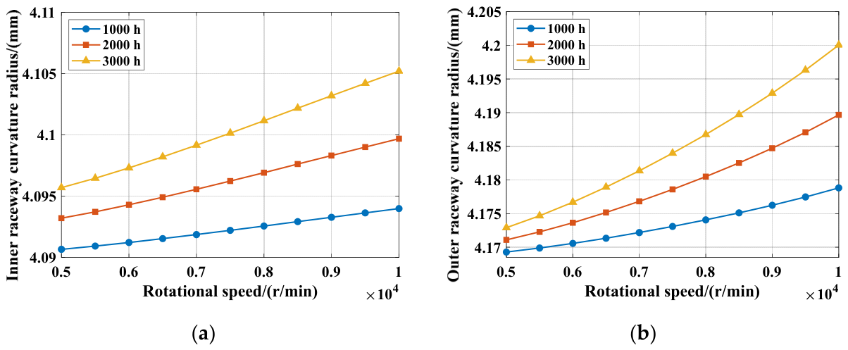
Variations in the curvature radii of the inner and outer raceways with wear. (a) Variation of the inner raceway curvature radius with wear time; (b) Variation of the outer raceway curvature radius with wear time.
Figure 23.
Variations in the curvature radii of the inner and outer raceways with wear. (a) Variation of the inner raceway curvature radius with wear time; (b) Variation of the outer raceway curvature radius with wear time.
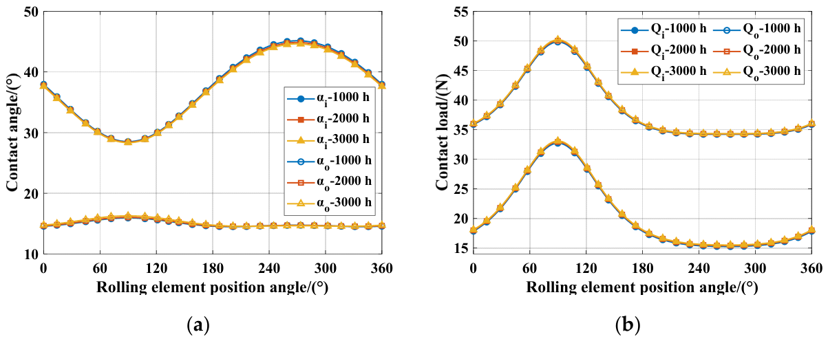
Figure 24.
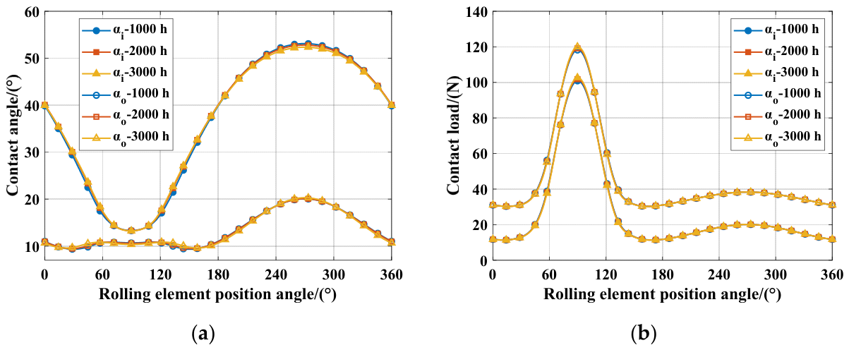
Contact angles and contact loads of the inner and outer raceways. (a) Variation of the raceway contact angle with wear time; (b) Variation of the raceway contact load with wear time.
Figure 24.
Contact angles and contact loads of the inner and outer raceways. (a) Variation of the raceway contact angle with wear time; (b) Variation of the raceway contact load with wear time.
Figure 25.
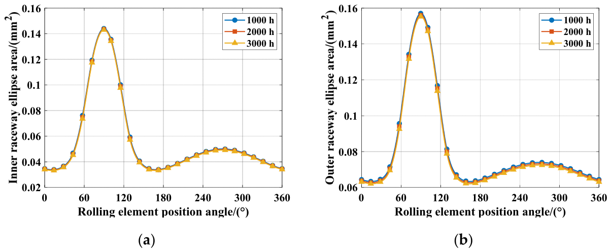
Effect of wear on the contact ellipse area. (a) Variation of inner contact ellipse area with wear time; (b) Variation of outer contact ellipse area with wear time.
Figure 25.
Effect of wear on the contact ellipse area. (a) Variation of inner contact ellipse area with wear time; (b) Variation of outer contact ellipse area with wear time.
Figure 26.
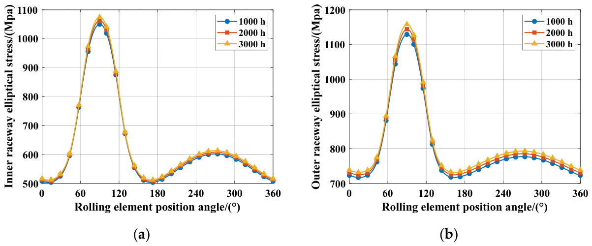
Effect of wear on the contact stress. (a) Inner contact ellipse contact stress versus wear time; (b) Outer contact ellipse contact stress versus wear time.
Figure 26.
Effect of wear on the contact stress. (a) Inner contact ellipse contact stress versus wear time; (b) Outer contact ellipse contact stress versus wear time.
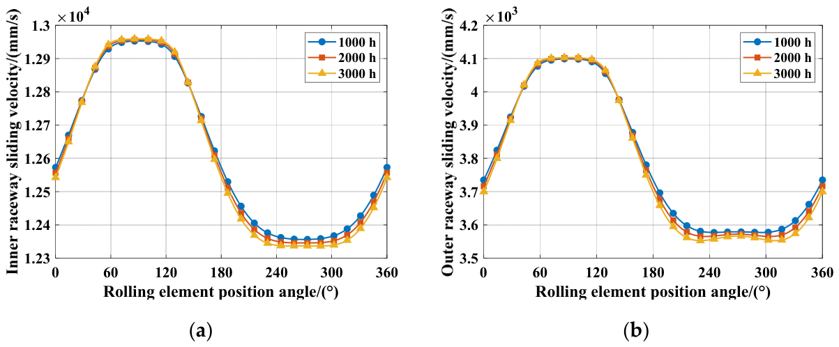
Figure 27.
Effect of wear on the sliding velocity. (a) Inner contact ellipse sliding velocity versus wear time; (b) Outer contact ellipse sliding velocity versus wear time.
Figure 27.
Effect of wear on the sliding velocity. (a) Inner contact ellipse sliding velocity versus wear time; (b) Outer contact ellipse sliding velocity versus wear time.
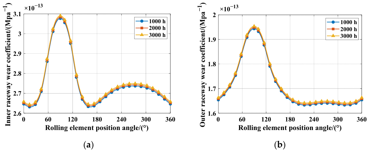
Figure 28.
Effect of wear on the wear coefficient of the inner and outer raceways. (a) Inner raceway wear coefficient versus wear time; (b) Outer raceway wear coefficient versus wear time.
Figure 28.
Effect of wear on the wear coefficient of the inner and outer raceways. (a) Inner raceway wear coefficient versus wear time; (b) Outer raceway wear coefficient versus wear time.
Figure 29.
Numerical calculation of bearing wear life.
Figure 29.
Numerical calculation of bearing wear life.
Figure 30.
Contact angles and contact loads of the inner and outer raceways. (a) Variation of the raceway contact angle with wear time; (b) Variation of the raceway contact load with wear time.
Figure 30.
Contact angles and contact loads of the inner and outer raceways. (a) Variation of the raceway contact angle with wear time; (b) Variation of the raceway contact load with wear time.
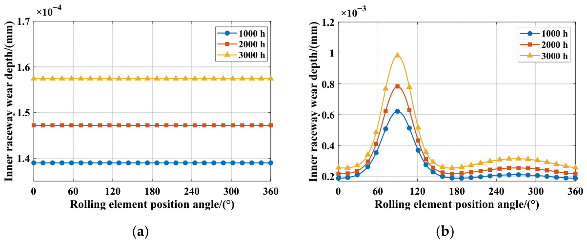
Figure 31.
Effect of raceway condition on wear depth. (a) Variation of inner raceway wear depth with wear time; (b) Variation of outer raceway wear depth with wear time.
Figure 31.
Effect of raceway condition on wear depth. (a) Variation of inner raceway wear depth with wear time; (b) Variation of outer raceway wear depth with wear time.
Table 1.
Design parameters of the SKF 7012ACE/HCP4A bearing.
Table 1.
Design parameters of the SKF 7012ACE/HCP4A bearing.
| Bearing Design Parameters | Value |
|---|
| Inner raceway curvature radius ri/o /(mm) | 4.08807 |
| Outer raceway curvature radius ri/o /(mm) | 4.16745 |
| Initial contact angle α0/(°) | 25 |
| Number of rolling elements z | 25 |
| Rolling element diameter D/(mm) | 7.938 |
| Pitch circle diameter Dm/(mm) | 77.591 |
| Density (kg/m3) | 7800 |
| Elastic modulus (Mpa) | 2.07 × 10⁵ |
| Poisson’s ratio | 0.28 |
Table 2.
Design parameters of the 7011C bearing [
43].
Table 2.
Design parameters of the 7011C bearing [
43].
| Bearing Design Parameters | Value |
|---|
| Inner raceway curvature radius ri/o /(mm) | 5.72 |
| outer raceway curvature radius ri/o /(mm) | 5.72 |
| Initial contact angle α0/(°) | 15 |
| Number of rolling elements z | 17 |
| Rolling element diameter D/(mm) | 11 |
| Pitch circle diameter Dm/(mm) | 72.5 |
| Density (kg/m3) | 7850 |
| Elastic modulus (Mpa) | 2 × 10⁵ |
| Poisson’s ratio | 0.3 |
Table 3.
Design parameters of the RPF7039 bearing [
44].
Table 3.
Design parameters of the RPF7039 bearing [
44].
| Bearing Design Parameters | Value |
|---|
| Inner/outer raceway curvature radius ri/o /(mm) | 9.16/9.38 |
| Initial contact angle α0/(°) | 40 |
| Number of rolling elements z | 12 |
| Rolling element diameter D/(mm) | 17.7 |
| Pitch circle diameter Dm/(mm) | 72.5 |
Table 4.
Verification of the bearing stiffness solution.
Table 4.
Verification of the bearing stiffness solution.
| Stiffness/(N∙mm−1) | Experimental
Result [44] | Present Result | Error/(%) |
|---|
| Axial stiffness | 226,011.1 | 230,175.1 | 1.8 |
| Radial stiffness | 172,131.6 | 166,519.9 | −3.3 |
| Radial stiffness | 155,520.7 | 166,504.6 | 7.1 |
| Angular stiffness | 139,304,365.4 | 143,212,104.9 | 2.8 |
| Angular stiffness | 157,160,958.5 | 153,228,230.2 | −2.5 |
Table 5.
Numerical calculation results of contact angle and contact load.
Table 5.
Numerical calculation results of contact angle and contact load.
| Calculation Parameter | Inner Raceway | Outer Raceway |
|---|
| Contact angle | 13.344° | 10.696° |
| Contact load | 99.812 N | 117.194 N |
Table 6.
Numerical calculation results of the sliding velocity on the contact ellipse.
Table 6.
Numerical calculation results of the sliding velocity on the contact ellipse.
| Calculation Parameter | Inner Contact Ellipse | Outer Contact Ellipse |
|---|
| Semi-major axis | 0.6907 mm | 0.5789 mm |
| Semi-minor axis | 0.0659 mm | 0.0858 mm |
| Max sliding (ωsi = 0 rad/s) | 26,295 mm/s | 12,894 mm/s |
| Min sliding (ωsi = 0 rad/s) | −13,148 mm/s | −25,789 mm/s |
| Max sliding (ωsi = 2000 rad/s) | 26,300 mm/s | 14,610 mm/s |
| Min sliding (ωsi = 2000 rad/s) | −14,466 mm/s | −25,808 mm/s |
| Max sliding (ωsi = 5000 rad/s) | 26,360 mm/s | 17,184 mm/s |
| Min sliding (ωsi = 5000 rad/s) | −16,443 mm/s | −25,908 mm/s |
| Max sliding (ωsi = 10,000 rad/s) | 26,566 mm/s | 21,474 mm/s |
| Min sliding (ωsi = 10,000 rad/s) | −19,738 mm/s | −26,265 mm/s |
Table 7.
Parameter values used for the calculation of the wear coefficient [
47].
Table 7.
Parameter values used for the calculation of the wear coefficient [
47].
| Calculation Parameters for the Wear Coefficient | Literature Result |
|---|
| Contact pair material parameters α * | 3.433 × 10⁻⁸ |
| Lubricant characteristic parameters β * | −1.032 |
| Brinell hardness of bearing material H/(Mpa) | 8470 |
| RMS roughness of rolling element surface σr /(μm) | 0.18 |
| RMS roughness of raceway surface σr/(μm) | 0.18 |
| Pressure–viscosity coefficient of lubricant ξ/(m2/N) | 2.2 × 10⁻⁸ |
| Absolute viscosity of lubricant η0/(Pa·s) | 0.04 |
| Effective elastic modulus E/(Mpa) | 1.12 × 10⁵ |
Table 8.
Variation of the peak wear coefficient of the inner raceway with rotational speed.
Table 8.
Variation of the peak wear coefficient of the inner raceway with rotational speed.
| Rotational Speed | Direction Wear Coefficients | Direction Wear Coefficients |
|---|
| 8000 r/min | 3.4482 × 10⁻¹³ | 3.0193 × 10⁻¹³ |
| 9000 r/min | 3.1717 × 10⁻¹³ | 2.7879 × 10⁻¹³ |
| 10,000 r/min | 2.9441 × 10⁻¹³ | 2.6184 × 10⁻¹³ |
Table 9.
Variation of the peak wear coefficient of the outer raceway with rotational speed.
Table 9.
Variation of the peak wear coefficient of the outer raceway with rotational speed.
| Rotational Speed | Direction Wear Coefficients | Direction Wear Coefficients |
|---|
| 8000 r/min | 2.1701 × 10⁻¹³ | 1.9053 × 10⁻¹³ |
| 9000 r/min | 2.0001 × 10⁻¹³ | 1.7205 × 10⁻¹³ |
| 10,000 r/min | 1.8597 × 10⁻¹³ | 1.5697 × 10⁻¹³ |
Table 10.
Variation of the peak wear coefficient of the inner raceway with radial load.
Table 10.
Variation of the peak wear coefficient of the inner raceway with radial load.
| Rotational Speed | Direction Wear Coefficients | Direction Wear Coefficients |
|---|
| 100 N | 3.1881 × 10⁻¹³ | 3.0052 × 10⁻¹³ |
| 200 N | 3.3459 × 10⁻¹³ | 3.0125 × 10⁻¹³ |
| 300 N | 3.4482 × 10⁻¹³ | 3.0193 × 10⁻¹³ |
Table 11.
Variation of the peak wear coefficient of the outer raceway with radial load.
Table 11.
Variation of the peak wear coefficient of the outer raceway with radial load.
| Rotational Speed | Direction Wear Coefficients | Direction Wear Coefficients |
|---|
| 100 N | 2.0296 × 10⁻¹³ | 1.8983 × 10⁻¹³ |
| 200 N | 2.1144 × 10⁻¹³ | 1.9001 × 10⁻¹³ |
| 300 N | 2.1701 × 10⁻¹³ | 1.9053 × 10⁻¹³ |
Table 12.
Variation of the peak contact ellipse area with time.
Table 12.
Variation of the peak contact ellipse area with time.
| Operating Time | Direction
(Inner Raceway/Outer Raceway) | Direction
(Inner Raceway/Outer Raceway) |
|---|
| 1000 h | 0.1441 mm2/0.1571 mm2 | 0.0500 mm2/0.0741 mm2 |
| 2000 h | 0.1435 mm2/0.1561 mm2 | 0.0496 mm2/0.0732 mm2 |
| 3000 h | 0.1430 mm2/0.1553 mm2 | 0.0492 mm2/0.0725 mm2 |
Table 13.
Variation of the peak contact stress at the center of the contact ellipse with time.
Table 13.
Variation of the peak contact stress at the center of the contact ellipse with time.
| Operating Time | Direction
(Inner Raceway/Outer Raceway) | Direction
(Inner Raceway/Outer Raceway) |
|---|
| 1000 h | 1050.00 Mpa/1129.16 Mpa | 601.86 Mpa/776.92 Mpa |
| 2000 h | 1062.68 Mpa/1144.05 Mpa | 607.49 Mpa/785.33 Mpa |
| 3000 h | 1074.59 Mpa/1157.87 Mpa | 612.86 Mpa/793.12 Mpa |
Table 14.
Variation of the peak sliding velocity at the center of the contact ellipse with time.
Table 14.
Variation of the peak sliding velocity at the center of the contact ellipse with time.
| Operating Time | Direction
(Inner Raceway/Outer Raceway) | Direction
(Inner Raceway/Outer Raceway) |
|---|
| 1000 h | 12,953 mm/s/4099 mm/s | 12,356 mm/s/3579 mm/s |
| 2000 h | 12,957 mm/s/4102 mm/s | 12,346 mm/s/3572 mm/s |
| 3000 h | 12,960 mm/s/4103 mm/s | 12,337 mm/s/3566 mm/s |
Table 15.
Variation of the peak wear coefficient with time.
Table 15.
Variation of the peak wear coefficient with time.
| Operating Time | Direction
(Inner Raceway/Outer Raceway) | Direction
(Inner Raceway/Outer Raceway) |
|---|
| 1000 h | 3.0771 × 10⁻¹³/1.9437 × 10−13 | 2.7367 × 10⁻¹³/1.6406 × 10−13 |
| 2000 h | 3.0841 × 10⁻¹³/1.9487 × 10−13 | 2.7430 × 10⁻¹³/1.6449 × 10−13 |
| 3000 h | 3.0909 × 10⁻¹³/1.9538 × 10−13 | 2.7493 × 10⁻¹³/1.6492 × 10−13 |
Table 16.
Average wear depth of the inner raceway and peak wear depth of the outer raceway.
Table 16.
Average wear depth of the inner raceway and peak wear depth of the outer raceway.
| Operating Time | Inner Raceway Average Wear Depth | Outer Raceway Peak Wear Depth |
|---|
| 1000 h | 1.39 × 10⁻⁴ mm | 6.22 × 10⁻⁴ mm |
| 2000 h | 1.47 × 10⁻⁴mm | 7.83 × 10⁻⁴ mm |
| 3000 h | 1.57 × 10⁻⁴mm | 9.83 × 10⁻⁴mm |





 ,
,