Article

Displacement Centre of Gravity and Stability Arm in Longitudinal Tilt of a Floating Body with Circular Floats

Department of Machine and Industrial Design, Faculty of Mechanical Engineering, VSB–Technical University of Ostrava, 17, listopadu 2172/15, Poruba, 708 00 Ostrava, Czech Republic
*
Author to whom correspondence should be addressed.
Machines 2026, 14(5), 576; https://doi.org/10.3390/machines14050576
Submission received: 22 April 2026 / Revised: 15 May 2026 / Accepted: 17 May 2026 / Published: 21 May 2026
(This article belongs to the Section Automation and Control Systems)

Abstract

Floating belt conveyor routes consisting of serially arranged belt conveyors, the end parts of which are mechanically attached to floating bodies, are designed for the continuous transport of extracted granular materials from water. This paper deals with the analytical determination of the position of the centre of gravity of the buoyancy force, the coordinates of which change depending on the longitudinal deflection of the floating body from the equilibrium state, which acts as a supporting element of individual conveyor belts. Analysis of the individual phases of deflection of the floating body, consisting of a pair of floats with a circular cross-section, shows that the complete submergence of one of the floats occurs at a higher value of the angle of inclination in the case when the floats are initially submerged under the surface to exactly half their diameter. On the realized experimental device, the buoyancy force was detected using strain gauges during the deflection of the floating body from the equilibrium position for three defined levels of immersion. The floating body of the experimental device consists of a pair of floats with a circular cross-section with a diameter of 80 mm. The output is a structured methodological procedure for determining the position of the centre of gravity of the displacement (centre of buoyancy) of a floating body when it deviates from the equilibrium position and a methodology for calculating the stability arm, which is a key parameter for assessing the buoyancy and stability of the body. On the basis of the laboratory measurements, the magnitude of the buoyancy force can be quantified as a function of the immersion depth of the floating body. It was found that the buoyancy force remains constant when the body deflects only when the immersion corresponds to half the diameter of a float with a circular cross-section. If the depth of the immersion is less than the radius of the float, the buoyancy force increases during deflection; however, if the immersion is greater than the radius of the float, the buoyancy force decreases.

1. Introduction

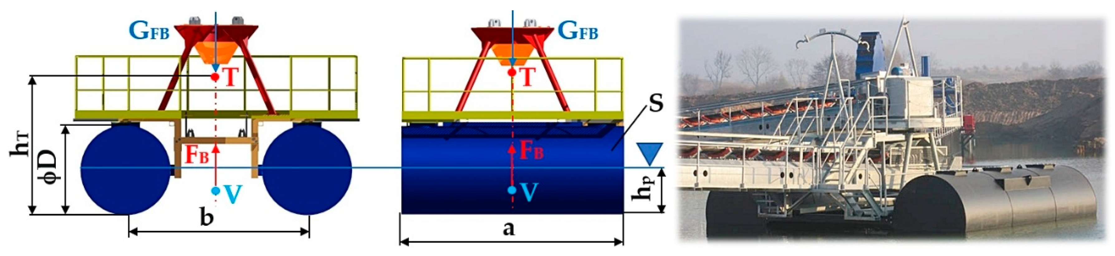
Floating belt conveyors [1] consist of two floating bodies [2], co called pontoons, of a rectangular [3] or circular [4] cross-section, as shown in Figure 1, with several watertight chambers, equipped with overflows and a turning mechanism.
The main objective of this paper is to investigate the buoyancy of floating conveyors; considering the loss of stability, this is essential to ensure their safe and reliable operation. Understanding the mechanisms that lead to loss of stability helps to prevent accidents, minimize the risk of damage to equipment and the surrounding environment, and optimize the design of conveyors. At the same time, it contributes to more efficient operation, extended equipment life and reduced economic losses associated with breakdowns or downtime.
When designing the floating bodies of floating belt conveyors in the design of end floats, it is necessary to ensure the condition of unsinkability [5,6]. The unsinkability of the floating body of a floating conveyor belt is defined as the floating body’s ability to retain its buoyancy [2,7,8,9] when one or more of its parts are flooded. In practice, unsinkability is ensured by dividing the partial floats by watertight transverse or even longitudinal watertight bulkheads into so-called chambers. In order to ensure unsinkability [10,11,12], it is necessary to determine the optimum location and the minimum number of these chambers, because flooding of the sub-chambers results in a change in the displacement and mean draught, a change in the longitudinal slope and a reduction in the metacentric stability height (the effect of the free surface in the flooded chambers).
For floating bodies, stability is important [13,14]. A body floats stably if, when deflected, a pair of forces acts on the body to bring it back to its original equilibrium position. A floating body can have essentially three positions [15,16]: stable (steady), unstable (wobbly) and indifferent (free).
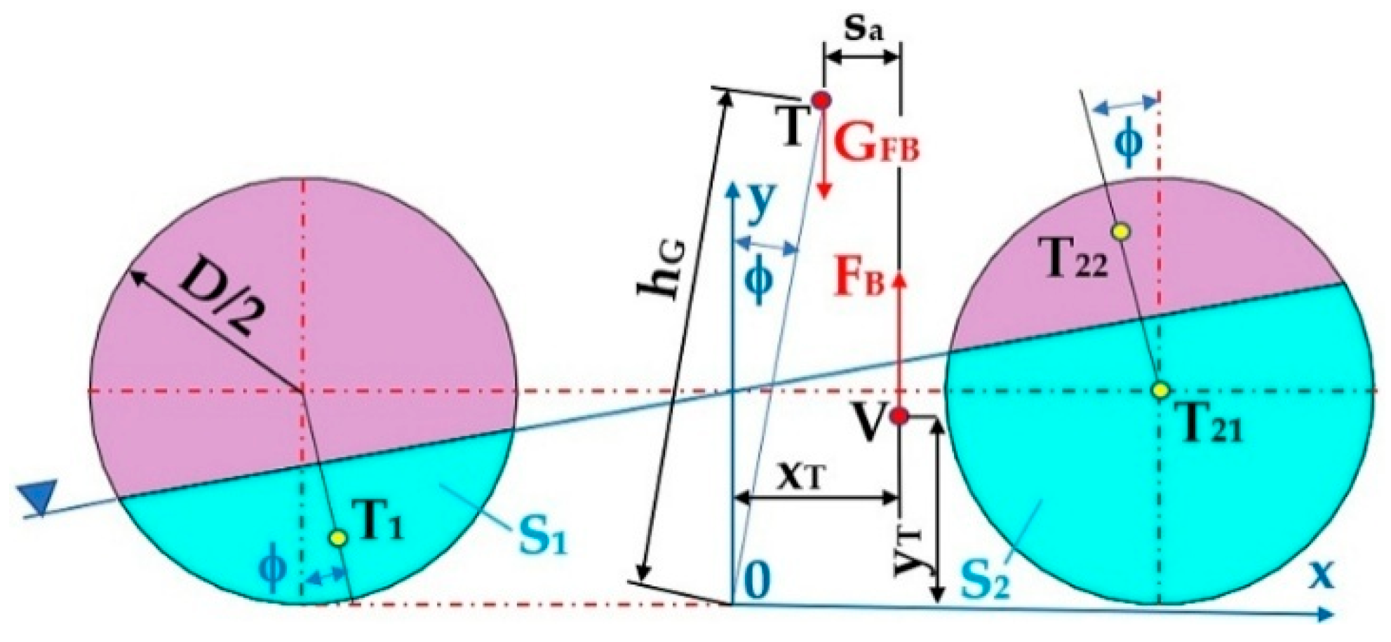
For floating bodies, two points [1] are most important, which lie on a common vertical axis, the so-called axis of floating, during equilibrium. These denote the centre of gravity “T” of the floating body, on which the gravitational force G F B   N of the body acts, and the centre of gravity “V” of the liquid body of volume V m 3 displaced by the floating body, the point on which the buoyant force F B N acts—see Figure 2.
For a homogeneous body [17], point T is always above point V . In the centre of gravity T of a body, the downward force of gravity G F B N tries to take the lowest possible position after the body is deflected, whereas the centre of gravity V , on which the upward force of buoyancy F B N acts, takes the highest possible position [1,2]. If we move the body out of this position by a small angle ϕ   [ d e g ] , the shape of the liquid body changes, although its volume V m 3 is preserved—the position of the centre of gravity T changes. When a floating body is deflected from a stable position, forces F B N , [N], and G F B N , are generated, which, through moment of force, return the deflected body to its equilibrium position. The stable position is easily judged by point M [2], which is the intersection of the buoyancy force carrier and the deflected axis of float. Point M is called the metacenter [1] and the distance T M [2] is the metacentric height. For a stably floating body, point M is above point T and the metacentric height T M is defined as positive. The greater the metacentric height T M , the faster the deflected body returns to its equilibrium position.
If the metacentre M falls below the centre of gravity T , the body is in an unstable position when floating, because when it is deflected from its equilibrium position by a small angle ϕ   [ d e g ] , a pair of forces, F B N and G F B N , begins to act on the body through a knock-on moment of force, which overturns it. The metacentric height T M is negative in this case.
In addition to the stable and labile position, the body may be in an indifferent position, where the metacentre M is at the centre of gravity “M”. If in the indifferent position during floating, there is probably a longer rotating cylinder with a horizontal axis or a sphere [1,2]. The metacentric height T M is zero.
Buoyancy [18] is defined as the ability of a body to float on a still liquid surface through the action of hydrostatic buoyancy [19]. Buoyancy is one of the basic properties of a floating body, characterized by the ability of the body to remain in equilibrium when immersed in a liquid. The buoyancy reserve is defined as the mass amount of load the floating body is capable of carrying before the total immersion of the floating body in liquid [20].
Stability [21,22] inherently falls into a broader group of the navigation properties of floating bodies. The stability of a floating body [23,24] is defined as its ability to return to its equilibrium position after deflection if the external forces causing the deflection cease to act on it.
According to the direction of deflection of the floating body, two variants of stability are recognized, “transverse” stability [25,26,27] and “longitudinal” stability.
Depending on the deflection of the floating body, we can distinguish between “initial” stability and “high angle of heel” stability.
According to the time effect of external forces and the influence of the inertia of masses, it is possible to define “static” stability (which is defined by the magnitude of the return moment when the body is deflected from the equilibrium position) and “dynamic” stability (which is determined by the amount that the floating body is able to absorb when deflected from the equilibrium position).
The issue of stability in floating belt conveyors has not yet been fully investigated systematically, especially in the case of floating body designs using floats with circular cross-sections [28,29]. These specific floating body designs can significantly affect the buoyancy distribution, the position of the centre of gravity and the overall stability behaviour of the system, but the available literature only marginally addresses this area. Insufficient knowledge of these influences poses a risk in the design and operation of the equipment, especially in terms of the possibility of loss of stability under variable operating conditions. Detailed research on this issue is therefore necessary to gain a deeper understanding of the behaviour of these systems, to refine design methods and to improve the safety and reliability of floating conveyors.
The current state of knowledge in the field of the stability of floating bodies was analyzed looking at the available literature. It was found that the vast majority of publications searched focus mainly on the buoyancy and stability of ships, while the specific area of floating conveyor belts remains virtually uncovered in professional sources. This disparity points to an existing gap in the research and highlights the need for a focused study of the stability of these devices, whose design and operating conditions differ from conventional vessels in many respects.
The stability of a floating body with a rectangular cross-section is addressed in [30,31]. For these types of floating bodies, the coordinates of the centre of gravity of the buoyancy force can be determined at different immersion depths and angles of deflection of the floating body from the equilibrium state using the static moments of surfaces [1].

2. Materials and Methods

The detailed description of the procedures and methods used in this section is intended to ensure the transparency of the research, to enable reproducibility of the results and to support their use in subsequent studies or practical applications.
The total gravity G F B N acting on the floating body is assumed. The weight G F B N acts at the centre of gravity T , which is h T m away from the bottom plane of the floating body; see Figure 2. In the equilibrium position ( ϕ = 0   d e g ), the horizontal axes of the floats of the circular cross-section are parallel to the water surface. The buoyant force F B N must be in balance with the gravity G F B N   (1).
F B = ρ · V p · g = ρ · a · S · g = G F B N
where ρ k g · m 3 is the density of water; V p   [ m 3 ] is the total volume of the submerged parts of the two floats (2); S m 2 is the submerged plan area of the floats; and a m is the length of the floats.
S o = π · D 2 4 m 2 ; V p = 2 · S 2 · a m 3
where D   [ m ] is the diameter of the circular float.

2.1. Longitudinal Tilt of the Float Body When the Floats Are Submerged h p = D 2 [ m ]

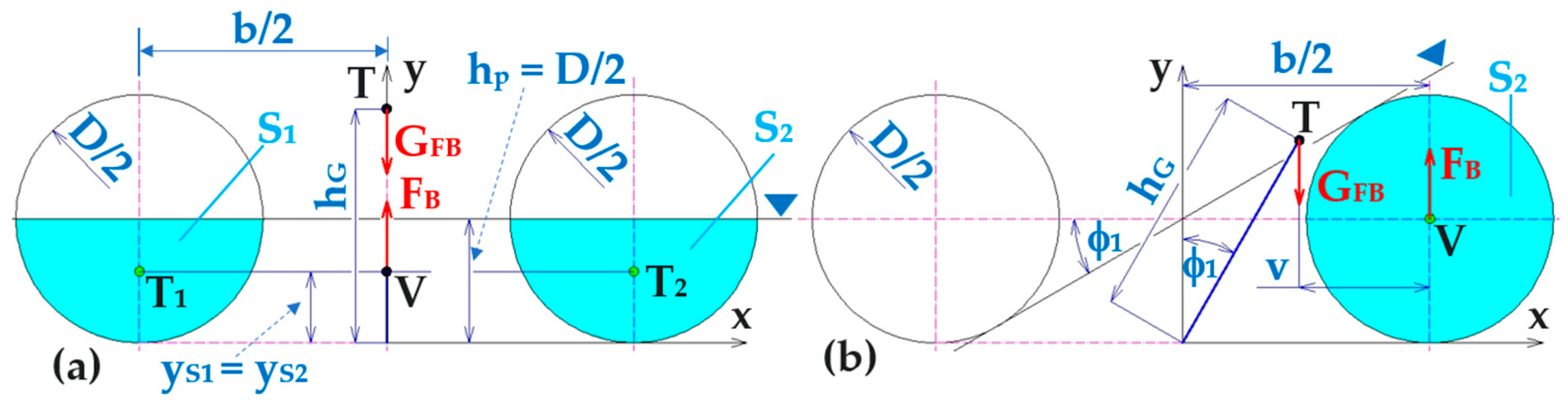
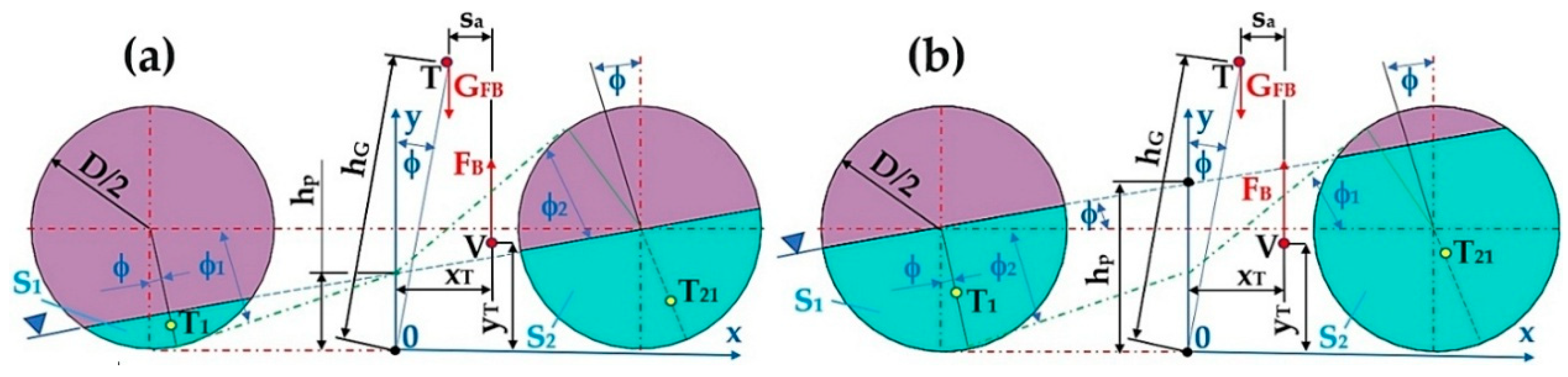
The 1st phase starts in the equilibrium position ϕ = ϕ 0 = 0 d e g , as shown in Figure 2, and ends with the right cylindrical float dipping below the surface ϕ = ϕ 1 d e g ( ϕ 1 = a s i n D b   [ d e g ] ).
The area S m 2 bounded by the circular faces of both floats (the left S 1 m 2 , as shown in Figure 3, and the right S 2 m 2 ) of its bottoms and surface can be expressed as shown in Equation (3).
S = S 1 + S 2 m 2
where S 1   [ m 2 ] is the sumberged area of the left float and S 2   [ m 2 ] is the submerged area of the right float.
Figure 3. Floating body (a) in equilibrium state ϕ = 0   d e g ; (b) when deflected by an angle of ϕ = ϕ 1 d e g .
Machines 14 00576 g003
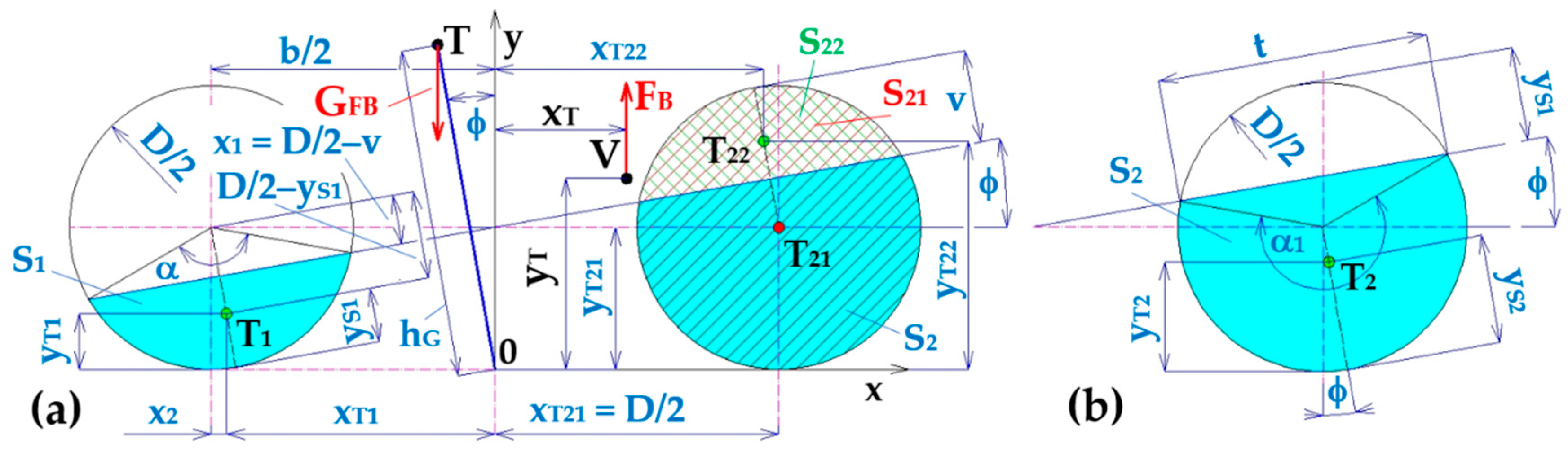
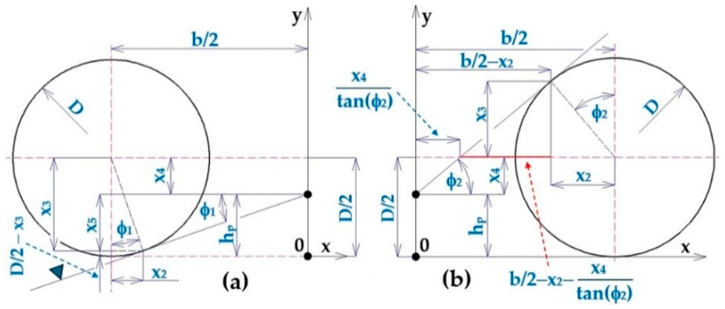
According to Figure 4, Equation (4) applies to the length x 1   [ m ] and the height of the circular segment v [ m ] .
s i n ϕ = 2 · x 1 b x 1 = s i n ϕ · b 2 m ; v = D 2 x 1   [ m ]
The central angle α d e g of the submerged area (circular segment) S 1 m 2 of the left float of the floating body can be expressed according to Equation (5).
α = 2 · a s i n x 1 D   [ d e g ]
The length of the chord t m , the angle α d e g (see Figure 4a) and the angle α 1 d e g (see Figure 4b) are given by Equation (6).
t = 2 · v · D v m ; α = 2 · a s i n t D d e g ; α 1 = 2 · π a s i n t D d e g
The distance of the centre of gravity y S 1 m of the submerged area S 1 m 2 of the left float, as shown in Figure 4a, and the distance of the centre of gravity y S 2 m of the immersed area S 2 m 2 of the right float, as shown in Figure 4b, can be expressed according to Equation (7).
y S 1 = 2 · D 2 3 · α 4 s i n α 4 s i n α 2 3 3 D 2 2 · α 2 s i n α 2 m ; y S 2 = 2 · D 2 3 · α 1 4 s i n α 1 4 s i n α 1 2 3 3 D 2 2 · α 1 2 s i n α 1 2 m
Area S 1 m 2 of the submerged part of the left float and the area of S 2 m 2 of the submerged part of the right float can be analytically determined according to Equation (8).
S 1 = 1 2 · D 2 2 · α s i n ( α ) m 2 ;   S 2 = D 2 2 · π α s i n ( α ) 2   [ m 2 ]
The coordinates of the centres of gravity of the sub-plots S 1 m 2 , S 21 m 2 and S 22 m 2 are given in Equations (9) and (10).
x T 1 = b 2 + D 2 y S 1 · s i n ϕ m ;   x T 21 = b 2 m ; x T 22 = b 2 D 2 y S 1 · s i n ϕ   [ m ]
y T 1 = D 2 D 2 y S 1 · c o s ϕ m ;   y T 21 = D 2 m ; y T 22 = D 2 + D 2 y S 1 · c o s ϕ   [ m ]
The coordinates of the centre of gravity of the displacement x T m , y T m are given by Equation (11).
x T = S 1 · x T 1 + S · x T 21 S 1 · x T 22 S m ;   y T = S 1 · y T 1 + S · y T 21 S 1 · y T 22 S m
The stability arm s a m , shown in Figure 5, is given by Equation (12).
s a = x T · c o s ϕ + y T · s i n ϕ h G · s i n ϕ   [ m ]
The coordinates of the centre of gravity x T , y T m , m of the buoyant force F B N of the floating body during the first phase of deflection 0 ϕ ϕ 1 d e g , analytically calculated according to (11) at the float immersion depth (in the equilibrium state ϕ = 0   d e g ) h p = 795   m m , are given in Table 1.
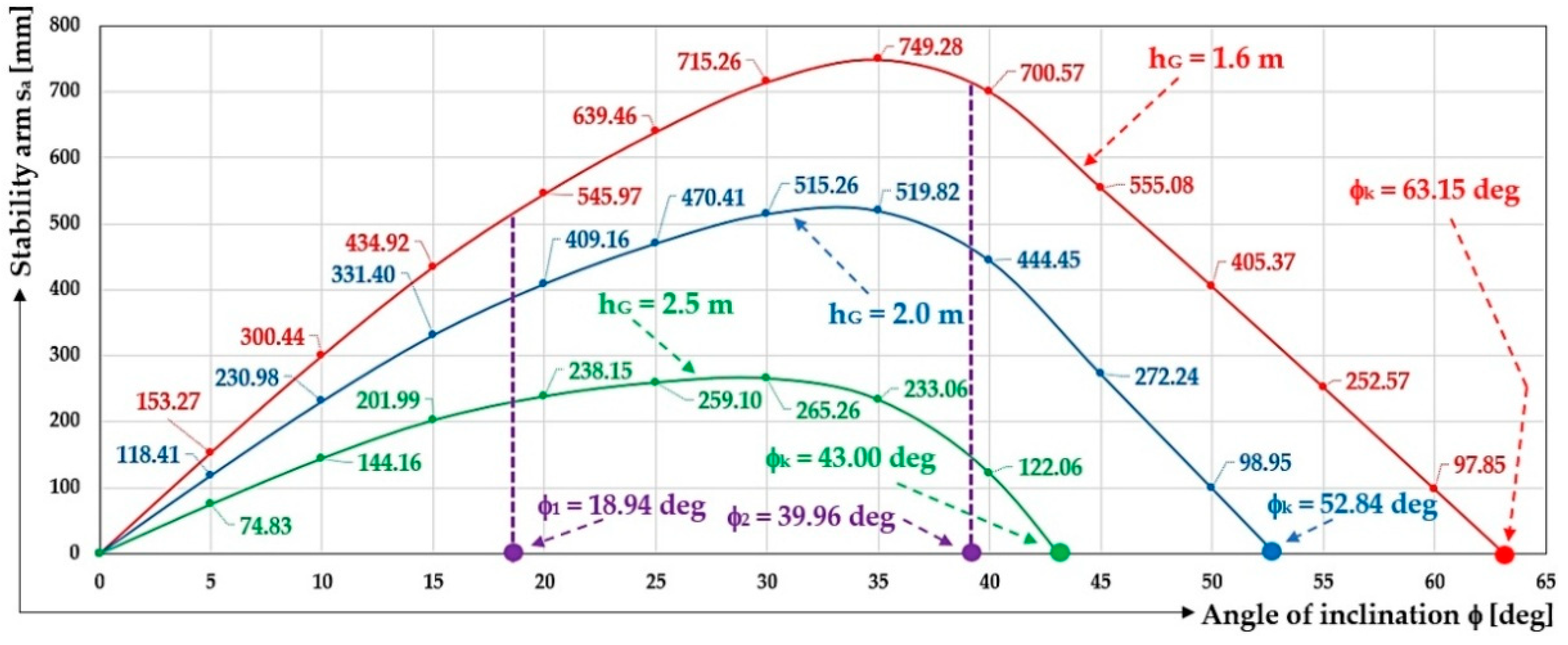
Figure 6 presents the size of the stability arm s a m (12) when the floating turntable is deflected out of equilibrium, with the immersion depth (in the steady state ϕ = 0   d e g ) of the floating body being h p = 795   m m .
The second phase begins by submerging the right cylindrical float below the surface ϕ = ϕ 1 = 30   d e g (13) and ends with the loss of buoyancy of the floating body ϕ k   [ d e g ] (13).
ϕ 1 = a s i n D b d e g ;   ϕ k = a t a n b 2 · h G D   [ d e g ]
The coordinates of the centre of gravity x T , y T m , m of the buoyancy force F B N of the floating body during the second phase of deflection ϕ 1 ϕ ϕ k , at the float immersion depth (in the equilibrium state ϕ = 0   d e g ) h p = 795   m m , are given in Table 2.
Figure 7 presents the deflection of the floating body during phase 2. The left float of the circular cross-section S 1 m 2 is completely above the water surface and the right float of the cross-section S 2 = S m 2 (2) is completely submerged below the water surface.

2.2. Longitudinal Tilt of the Float Body When the Floats Are Submerged h p < D 2 [ m ]

The total gravity G F B N acting on the floating body is assumed. The weight G F B N acts at the centre of gravity T, which is h T m away from the bottom plane of the floating body; see Figure 2. In the equilibrium position ( ϕ = 0   d e g ), the horizontal axes of the floats of circular cross-section are parallel to the water surface. The buoyant force F B N must be in balance with the gravity G F B N (1).
Displacement of the floating body from the equilibrium state during phase 1, when the floats h p < D 2 [ m ] and h p > D 2 [ m ] are submerged, is shown in Figure 8.
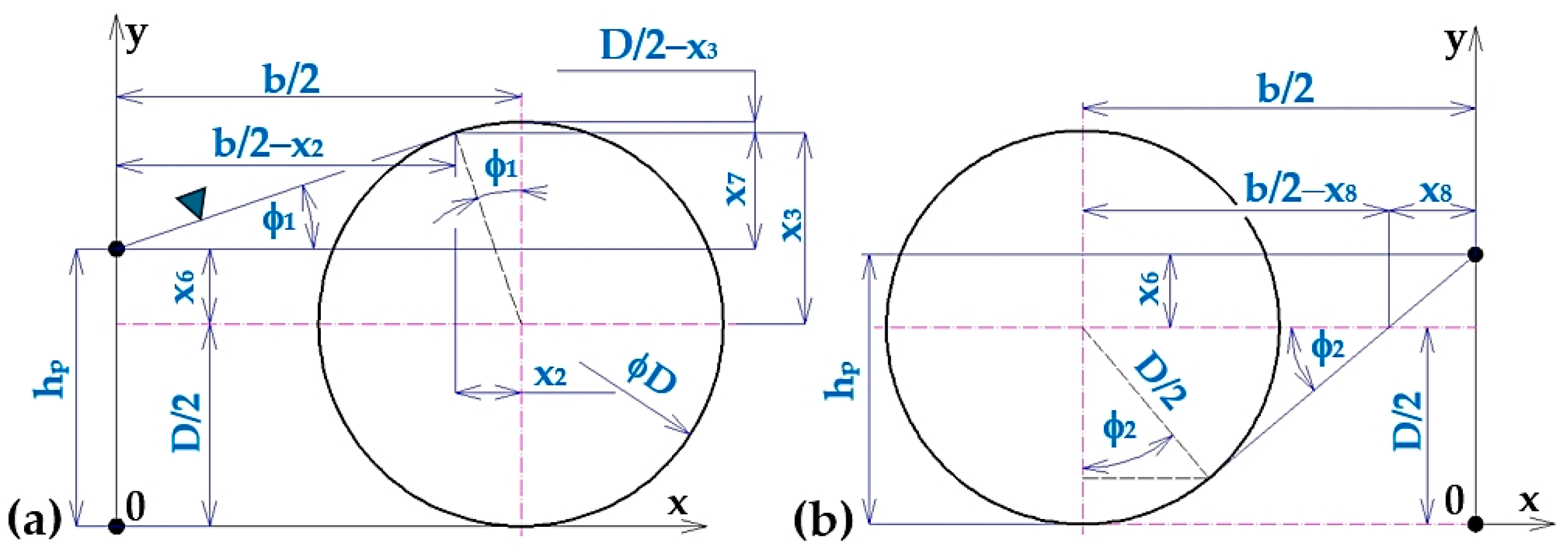
The 1st phase starts in the equilibrium position ϕ = ϕ 0 = 0 deg, as shown in Figure 2, and ends with the left float of the circular cross-section emerging from the water surface ϕ = ϕ 1 = 18.94   d e g (16); see Figure 9a.
x 2 = D 2 · s i n ϕ 1 m ;   x 3 = D 2 · c o s ϕ 1 m ; x 4 = D 2 h p m
x 5 = D 2 D 2 x 3 x 4 = D 2 · c o s ϕ 1 1 + h p m
t a n ϕ 1 = x 5 b 2 x 2 ϕ 1 = a t a n D 2 · c o s ϕ 1 1 + h p b 2 D 2 · s i n ϕ 1   [ d e g ]
The magnitude of the angle ϕ 1 = 18.94   d e g can be determined in the Mathcad programming environment (version 14.0.0.163) [32] by the “Given−Find” instruction, or analytically from quadratic Equation (17), derived from Equation (16); see (18).
A 1 · c o s ( ϕ 1 ) 2 + B 1 · cos ϕ 1 + C 1 = 0 ,
where A 1 = b 2 2 + h p D 2 2 m 2 ; B 1 = D · h p D 2 m 2 ;   C 1 = D 2 b 2 4 m 2 .
ϕ 1 = a c o s B 1 + B 1 2 4 · A 1 · C 1 2 · A 1   [ d e g ]
The coordinates of the centre of gravity x T , y T m , m of the buoyant force F B N of the floating body during the first phase of deflection 0 ϕ ϕ 1 d e g , where ϕ 1 d e g can be determined according to (16) and (18), at the float immersion depth (in the equilibrium state ϕ = 0   d e g ) h p = 500   m m , are given in Table 3.
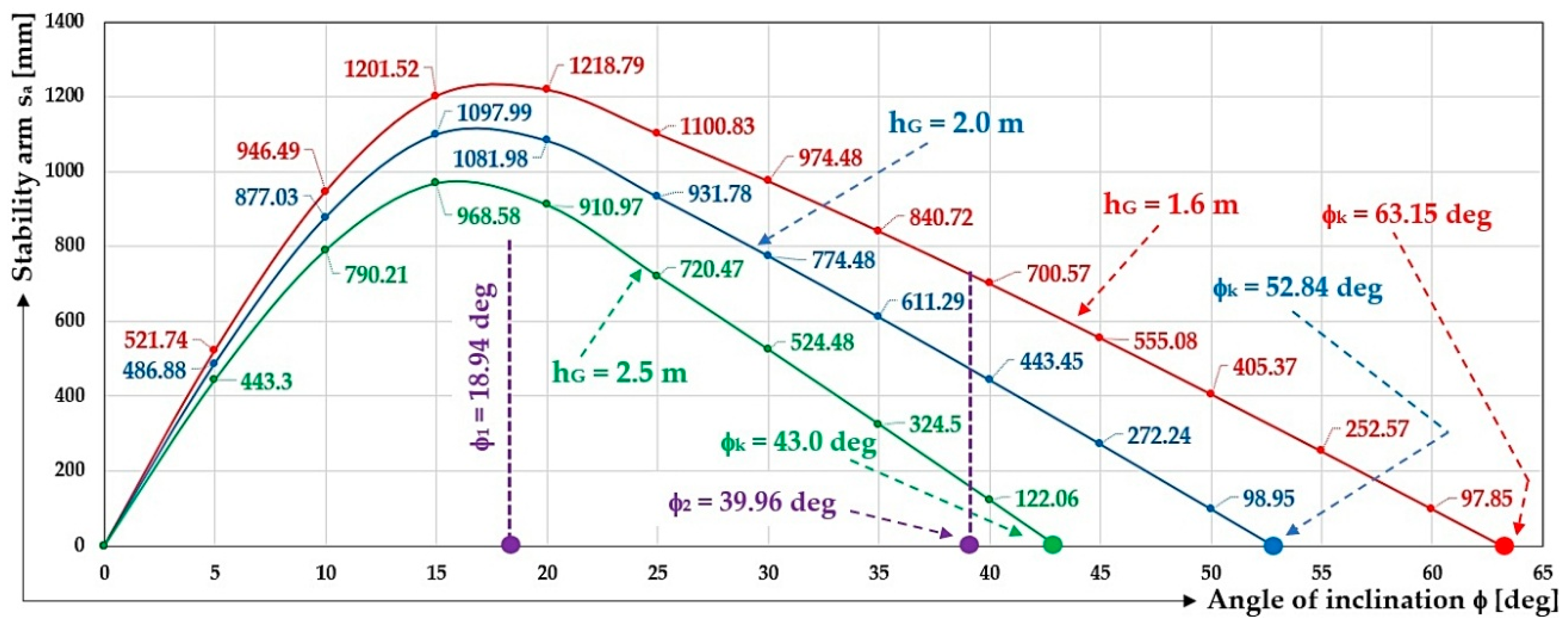
Figure 10 presents the size of the stability arm s a m (12) when the floating turntable is deflected out of equilibrium, with the float immersion depth (in the steady state ϕ = 0   d e g ) h p = 500   m m .
The 2nd phase begins with by bringing the left cylindrical float above the surface ϕ 1 = 18.94   d e g (see Figure 10) and ends after the right cylindrical float drops below the water surface ϕ = ϕ 2 d e g (19) ( ϕ 2 = 39.96   d e g ), as shown in Figure 9b, assuming that the distances x 2   [ m ] , x 3   [ m ] and x 4 m are determined by (14).
t a n ϕ 2 = x 3 b 2 x 4 t a n ϕ 2 x 2 ϕ 2 = a t a n D 2 · c o s ϕ 2 b 2 D 2 h p t a n ϕ 2 D 2 · s i n ϕ 2   [ d e g ]
The magnitude of the angle ϕ 2 = 39.96   d e g was solved in the Mathcad programming environment (version 14.0.0.163) [32] using “Given−Find”, or analytically from the quadratic Equation (20), derived from Equation (19); see (21).
A 2 · c o s ( ϕ 2 ) 2 + B 2 · cos ϕ 2 + C 2 = 0 ,
where A 2 · c o s ( ϕ 2 ) 2 + B 2 · cos ϕ 2 + C 2 = 0 .
ϕ 2 = a c o s B 2 + B 2 2 4 · A 2 · C 1 2 · A 2   [ d e g ]
The coordinates of the centre of gravity x T , y T m , m of the buoyancy force F B N of the floating body during the second phase of deflection ϕ 1 ϕ ϕ 2 d e g , and the magnitude of the angle ϕ 2 d e g —see (19) and (21)—at the float immersion depth (in the equilibrium state ϕ = 0   d e g ) h p = 500   m m , are given in Table 4.
The 3rd phase begins in the right cylindrical float below the water surface ϕ = ϕ 2 = 39.96 deg (19), (21), as shown in Figure 11b, and ends with the loss of buoyancy of the floating body ϕ k   [ d e g ] ; see Table 5.
The coordinates of the centre of gravity x T , y T m , m of the buoyancy force F B N of the floating body during the 3rd phase of deflection ϕ 2 ϕ ϕ k d e g at the float immersion depth (in the equilibrium state ϕ = 0   d e g ) h p = 500   m m are given in Table 5.

2.3. Longitudinal Tilt of the Float Body When the Floats Are Submerged h p > D 2 [ m ]

The 1st phase starts in the equilibrium position ϕ = ϕ 0 = 0 deg, as shown in Figure 2, and ends with the right float of the float body submerged below the water surface ϕ = ϕ 1 = 18.94   d e g (16), (18); see Figure 11a and Table 6.
x 6 = h p D 2   m ; x 7 = D 2 D 2 x 3 x 6 = D 2 · 1 + c o s ϕ 1 h p   m ; x 8 = x 6 t a n ϕ 2   m
where the distance x 3   [ m ] is stated in (14).
t a n ϕ 1 = x 7 b 2 x 2 ϕ 1 = a t a n D 2 · 1 + c o s ϕ 1 h p b 2 D 2 · s i n ϕ 1   [ d e g ]
The magnitude of the angle ϕ 1 = 18.94   d e g (23) was solved in the Mathcad programming environment (version 14.0.0.163) [32] by the “Given−Find” instruction or analytically from the quadratic Equation (24), derived from Equation (23); see (25).
A 3 · c o s ( ϕ 1 ) 2 + B 3 · cos ϕ 1 + C 3 = 0
where A 3 = A 2 m 2 ; B 3 = B 2 m 2 ; C 3 = C 1   [ m 2 ] .
ϕ 1 = a c o s B 2 + B 2 2 4 · A 2 · C 1 2 · A 2   [ d e g ]
The coordinates of the centre of gravity x T , y T m , m of the buoyant F B N force during the first phase of deflection 0 ϕ ϕ 1 d e g , analytically calculated according to (18) at the float immersion depth (in the equilibrium ϕ = 0   d e g ) h p = 1090   m m , are given in Table 6.
Table 6. Coordinates of the centre of gravity x T , y T m , m of the buoyancy force F B N of the floating body during phase 1 of deflection 0 ϕ ϕ 1 at immersion depth h p = 1090   m m .
b = 3.18 m; D = 1.59 m; h G = 1.6 m; h p = 1.09 m
ϕ d e g 0510152018.94 = ϕ 1 2
x T 10 3 · m 0239.82474.70700.12911.39868.56
x T · c o s ϕ 0238.91467.49676.26856.43821.54
y T 610.12617.42638.03667.53692.29689.34
y T · s i n ϕ 053.81110.79172.77236.78223.74
h G · s i n ϕ 0139.45277.84414.11547.23519.32
s a 10153.27300.44434.92545.97525.96
S 1 10 3 · m 2 14,508.3412,381.3010,157.057923.835769.696211.11
S 2 14,508.3416,447.8418,101.9119,345.4519,855.6519,855.65
V 1 10 6 · m 3 5,803,337.614,952,518.694,062,821.643,169,532.572,307,876.722,484,443.55
V 2 5,803,337.616,579,134.857,240,762.957,738,178.577,942,260.397,942,260.39
V11,606,675.2211,531,653.5511,303,584.5910,907,711.1410,250,137.1110,426,703.94
b = 3.18 m; D = 1.59 m; h G = 2.0 m; h p = 1.09 m
ϕ d e g 0510152018.94 = ϕ 1   2
h G · s i n ϕ 10 3 · m 0174.31347.3517.64684.04649.16
s a   10118.41230.98331.40409.16396.12
b = 3.18 m; D = 1.59 m; h G = 2.5 m; h p = 1.09 m
ϕ d e g 0510152018.94 = ϕ 1   2
h G · s i n ϕ 10 3 · m 0217.89434.12647.05855.05811.44
s a   1074.83144.16201.99238.15233.84
1 See Figure 12, 2 see Figure 11a.
Figure 11. Total draft of the (a) left float ϕ = ϕ 1 d e g and (b) right float ϕ = ϕ 2   d e g of the floating body at h p > D 2 [ m ] .
Machines 14 00576 g011
Figure 12 presents the size of the stability arm s a m (12) when the floating turntable is deflected from its equilibrium state, with the float immersion depth (in the steady state ϕ = 0   d e g ) h p = 1090   m m .
Figure 12. Stability arm size s a   m at deflection ϕ d e g of the floating turn from equilibrium, at h p = 1090   m m .
Machines 14 00576 g012
The 2nd phase begins by plunging the right float of the float body below the water surface ϕ 1 = 18.94   d e g (23), as shown in Figure 11a, and ends with the right float of the float body rising above the water surface ϕ 2 = 39.96   d e g (26); see Figure 11b and Table 7.
s i n ϕ 2 = D 2 b 2 x 8 ϕ 2 = a s i n D 2 b 2 h p D 2 t a n ϕ 2   [ d e g ]
where the distance x 8   [ m ] is as shown in (22).
The magnitude of the angle ϕ 2 = 39.96   d e g (26) was solved in the Mathcad programming environment (version 14.0.0.163) [32] by the “Given−Find” instruction, or analytically from the quadratic Equation (27), derived from Equation (26); see (28).
A 4 · c o s ( ϕ 2 ) 2 + B 4 · cos ϕ 2 + C 4 = 0
where A 4 = A 1 m 2 ; B 4 = B 1 m 2 ; C 4 = C 1 m 2 .
ϕ 2 = a c o s B 1 + B 1 2 4 · A 1 · C 1 2 · A 1   [ d e g ]
The coordinates of the centre of gravity x T , y T m , m of the buoyancy force F B N of the floating body during the second phase of deflection ϕ 1 ϕ ϕ 2 d e g , at the float immersion depth (in the equilibrium state ϕ = 0   d e g ) h p = 1090   m m , are given in Table 7.
The 3rd phase begins with the left cylindrical float rising above the water surface ϕ 2 = 39.96   d e g (26), as shown in Figure 11b, and ends with the loss of buoyancy of the floating body ϕ k   [ d e g ] ; see Table 8.
The coordinates of the centre of gravity x T , y T m , m of the buoyancy force F B N of the floating body during the 3rd phase of deflection ϕ 2 ϕ ϕ k d e g , at the float immersion depth (in the equilibrium state ϕ = 0   d e g ) h p = 1090   m m , are given in Table 8.

2.4. Analytical Calculation of the Longitudinal Stability of a Floating Turntable with Cylindrical Floats

In the equilibrium state of the floating body, when the immersion of both floats reaches the height h p = D 2 [ m ] , the area of the immersed surface of the left float S 1   [ m 2 ] (for α = π = 180   d e g ) can be expressed as shown in Figure 3 by Equation (8).
The total S   [ m 2 ] (2) immersion area of the two floats in the equilibrium state ( ϕ = 0   d e g ) corresponds to the sum of the immersion areas S 1   [ m 2 ] (8) and S 2   [ m 2 ] (8) of the two cylindrical floats.
When calculating the stability and buoyancy of a floating body consisting of floats of circular cross-section by numerical solution according to the calculation program created in the Mathcad environment (version 14.0.0.163) [32], it is necessary to decompose the solution into two basic directions. These two directions result from the defined limiting angle ϕ 1 d e g (13), which is defined as the tangent angle to the contours of the floats with respect to the horizontal plane; see Figure 3b.
The general angle ϕ   [ d e g ] of inclination of a floating body can take (with respect to the angle ϕ 1   [ d e g ] ) two values, described by the following states:
The 1st condition occurs when the tilt angle of the floating body ϕ   [ d e g ] is less than the angle ϕ 1   [ d e g ] and, at the same time, greater than 0   d e g ; see (29). A general illustration of this state of float body tilt is given in Figure 4a.
0 < ϕ ϕ 1 d e g   o r   0 < ϕ a s i n D b   [ d e g ]
The 2nd condition occurs when the tilt angle of the floating body ϕ   [ d e g ] is greater than the angle ϕ 1   [ d e g ] and, at the same time, less than π 2 = 90   d e g , as shown in Equation (30); see Figure 7.
ϕ 1 ϕ < 90   d e g   o r   a s i n D b ϕ < π 2 [ d e g ]
Now Equations (29) and (30) will be defined in more detail.
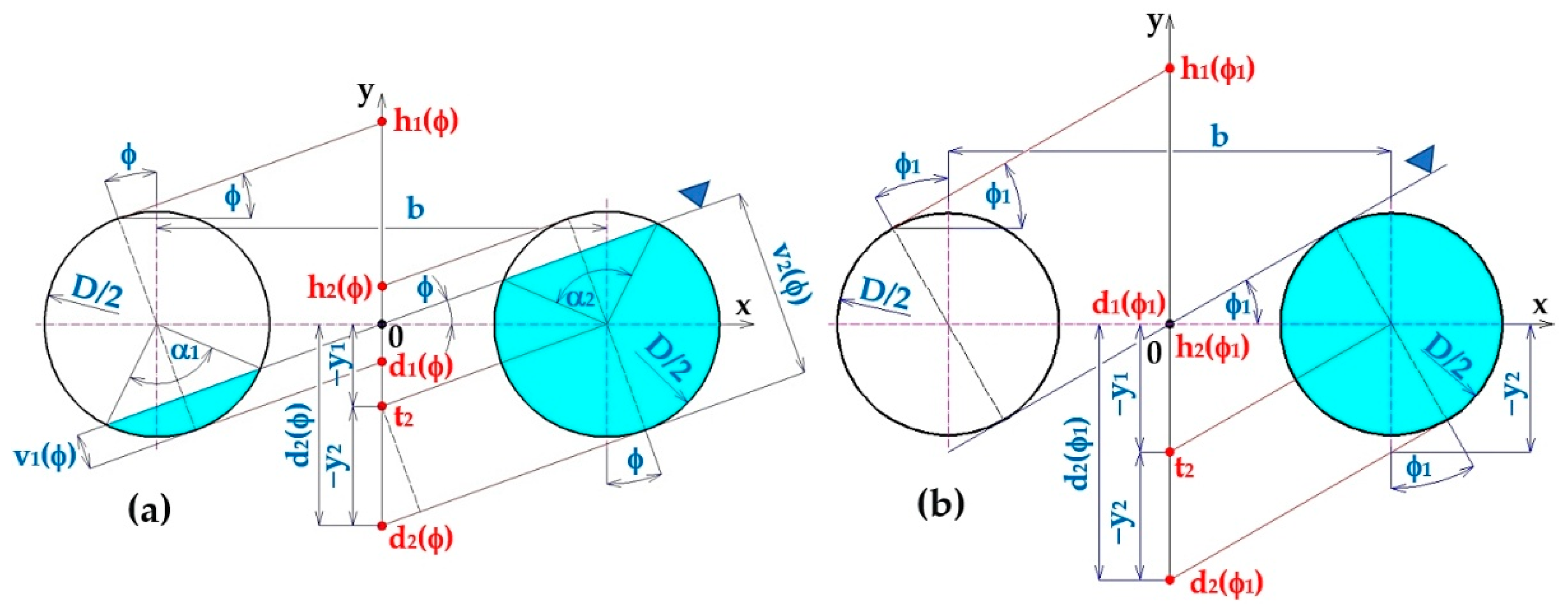
A general illustration of the floating body roll condition in which the float angle range is valid ϕ   [ d e g ]   (29) is given in Figure 13a.
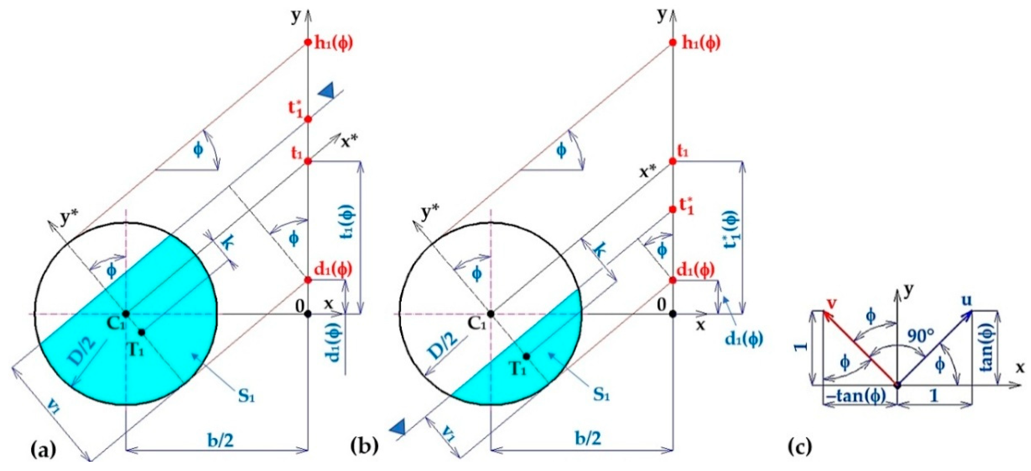
The distance of the intersection d 2 ϕ (this point is defined as the intersection of the tangent line with the vertical axis of symmetry of the floating body, drawn at an angle ϕ   [ d e g ] to the bottom of the right float) from the origin of the coordinate system, as shown in Figure 13a, can be expressed by Equation (31).
d 2 ϕ = y 1 y 2 = b 2 · t a n ϕ D 2 · c o s ϕ [ m ]
where y 1   [ m ] is the length of the segment on the y-axis expressed by Equation (32) using Figure 13a; y 2 m is the length of the segment on the y-axis expressed by Equation (33) using Figure 13a.
t a n ϕ = y 1 b / 2 y 1 = b 2 · t a n ϕ   [ m ]
c o s ϕ = D / 2 y 2 y 2 = D / 2 c o s   ( ϕ ) [ m ]
The intersection distance h 1 ϕ (this point is defined as the intersection of the tangent of the left float of the floating body with the vertical axis), as shown in Figure 13a, can be expressed by Equation (34).
h 2 ϕ = d 2 ϕ + 2 · y 2 = b 2 · t a n ϕ + D 2 · c o s ϕ m
The distance of the intersection d 1 ϕ (this point is defined as the intersection of the tangent line with the vertical axis of the floating body, drawn at an angle ϕ   [ d e g ] to the bottom of the left float) from the origin of the coordinate system, as shown in Figure 13a, can be expressed by Equation (35).
d 1 ϕ = h 2 ϕ = b 2 · t a n ϕ D 2 · c o s ϕ m
The distance of the intersection h 1 ϕ (this point is defined as the intersection of the tangent line with the vertical axis of symmetry of the floating body, drawn at an angle ϕ   [ d e g ] to the top of the left float from the origin of the coordinate system), as shown in Figure 13a, can be expressed by Equation (36).
h 1 ϕ = d 2 ϕ = b 2 · t a n ϕ + D 2 · c o s ϕ m
With an angle ϕ   [ d e g ] of inclination of the floating body within the range defined by Equation (29), the individual points (see Figure 13b) take on the following absolute magnitudes (37):
d 2 ϕ m < h 2 ϕ m d 1 ϕ m < h 1 ϕ m
The state of deflection of the floating body from the equilibrium position defined by Equation (29) must be further decomposed into two states, described by h p = D 2 m , h p < D 2 m and h p > D 2 m .
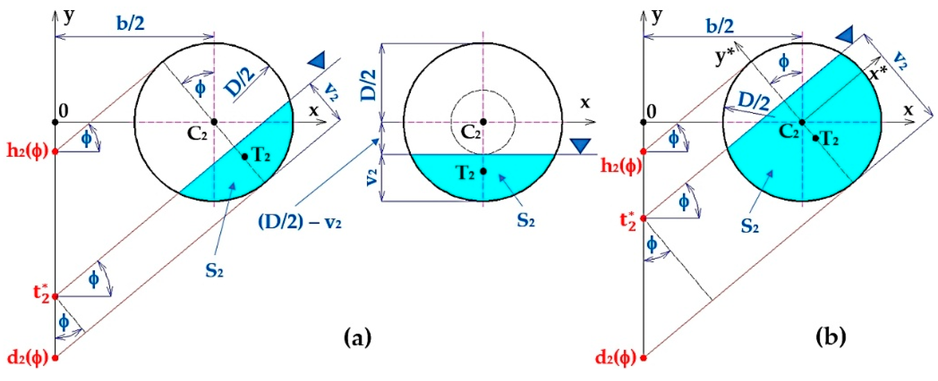
1a) The state of inclination of a floating body consisting of two cylindrical floats for which the angle ϕ   [ d e g ] of heeling is described by Equation (29) and the case where the position of the surface does not exceed the centre of the right float when the float is tilted; see Figure 14a.
Point t 2 * (the intersection of the water surface with the vertical axis of symmetry when the floating body is deflected from the equilibrium position) lies in the interval t 2 * d 2 ϕ ; h 2 ϕ .
The height v 2   [ m ] of the submerged part of the right float (height of the circular section) can be expressed according to Figure 14a by Equation (38).
c o s ϕ = v 2 t 2 * d 2 ϕ v 2 = t 2 * d 2 ϕ · c o s ϕ   [ m ]
The surface area S 2 t 2 *   [ m 2 ] of the submerged part of the right cylindrical float can be expressed based on Figure 14a by Equation (39).
S 2 t 2 * = D 2 D 2 + v 2 D 2 2 y 2 D 2 2 y 2 d x · d y m 2
The position of the centre of gravity T 2 t 2 *   [ m ] of the submerged part of the right cylindrical float can be expressed by Equation (40) based on Figure 14a.
T 2 t 2 * = 0 ; D 2 D 2 + t 2 * d 2 ϕ · c o s ϕ D 2 2 y 2 D 2 2 y 2 y · d x · d y S 2 t 2 * = 0 ; y 2 t 2 * m ; m
Position of the centre of gravity T 2 ϕ   [ m ] of the submerged part of the right float of a cylindrical floating body can be expressed where the plane of the water surface exceeds the centre of the float, as shown in Figure 14b, by Equation (41).
The centre of gravity T 2 ϕ   [ m ] of the immersed area S 2   [ m 2 ] of the right float is on a line perpendicular to a line whose origin passes through point t 2 , inclined at angle ϕ   [ d e g ] , at a distance of b / 2   [ m ] from the centre C 2 of the float. The coordinates of the position of the centre of gravity T 2   [ m ] of the immersed area S 2   [ m 2 ] of the right float can be expressed according Equation (41).
x T 2 ; y T 2 = b 2 ; 0 + k · t a n ϕ ; 1 1 + t a n ϕ 2 [ m ; m ]
where k [ m ] is the distance of the centre of gravity of the plunging surface of the right float from its centre; as shown in Figure 15c and Equation (44), this takes the size of y 2 . t a n ϕ ; 1 1 + t a n ϕ 2 is the size of the unit vector in the direction of the axis y * , as shown in Figure 15c.
Figure 15c shows the unit vector u = 1 ; t a n ϕ . From the mathematical analysis, the scalar product of two vectors, u = u 1 , u 2 and vector v = v 1 , v 2 , can be described by Equation (42); the result of the scalar product is a number. If the scalar product of two vectors is zero, these vectors are perpendicular to each other.
u · v = u 1 · v 1 + u 2 · v 2
If, according to Figure 15c, vector “v” is perpendicular to vector “u” its coordinates must be v = t a n ϕ ; 1 because then the condition that the scalar product of the two vectors is equal to zero is satisfied, as shown in Equation (43).
u · v = u 1 · v 1 + u 2 · v 2 = 1 · t a n ϕ + t a n ϕ · 1
T 2 t 2 * = b 2 ; 0 + y 2 t 2 * · t a n ϕ ; 1 1 + t a n ϕ 2 = b 2 t a n ϕ 1 + t a n ϕ 2 · y 2 t 2 * ; 1 1 + t a n ϕ 2 · y 2 t 2 * m ; m
The heeling condition of a floating body consisting of two cylindrical floats for which the angle ϕ   [ d e g ] of heel is described by Equation (29) and the surface plane exceeds the centre of the left float when the floating body is heeled; see Figure 15a. Point t 1 * (the intersection of the water surface with the vertical axis of symmetry of the floating turntable when the turntable is deflected from the equilibrium position) lies in the interval t 1 * d 1 ϕ ; h 1 ϕ .
According to Figure 15a, the height v 1   [ m ] of the submerged part of the left float (height of the circular section) can be determined by Equation (45).
c o s ϕ = v 1 ϕ t 1 * d 1 ϕ v 1 ϕ = t 1 * d 1 ϕ · c o s ϕ   [ m ]
The surface area S 1 t 1 * m 2 of the submerged part of the left cylindrical float can be expressed by Equation (46) based on Figure 15a.
S 1 t 1 * = D 2 D 2 + v 1 ϕ D 2 2 y 2 D 2 2 y 2 d x · d y = D 2 D 2 + t 1 * d 1 ϕ · c o s ϕ D 2 2 y 2 D 2 2 y 2 d x · d y m 2
The position of the centre of gravity T 1 t 1 *   [ m ] of the submerged part of the left float of the cylindrical floating body can be expressed by the Equation (47) based on Figure 15a.
T 1 t 1 * = 0 ; D 2 D 2 + t 1 * d 1 ϕ · c o s ϕ D 2 2 y 2 D 2 2 y 2 y · d x · d y S 1 t 1 * = 0 ; y 1 t 1 * m ; m
The position of the centre of gravity T 1 ϕ   [ m ] of the submerged part of the left cylindrical float of the float body can be expressed, in the case where the plane of the water surface exceeds the centre of the float, by Figure 15b, using Equations (48) and (49).
x T 1 ; y T 1 = b 2 ; 0 + k · t a n ϕ ; 1 1 + t a n ϕ 2 [ m ; m ]
T 1 t 1 * = b 2 ; 0 + y 1 t 1 * · t a n ϕ ; 1 1 + t a n ϕ 2 = b 2 t a n ϕ 1 + t a n ϕ 2 · y 1 t 1 * ; 1 1 + t a n ϕ 2 · y 1 t 1 * m ; m
In case h p = D 2 m , when the right float is not completely submerged below the water surface and the left float is not above the water surface, i.e., ϕ < ϕ 1 d e g , the immersion depth of the right float can be v 2 ϕ m and the left float v 1 ϕ m can be expressed according to Equation (50).
v 1 ϕ = D 2 b 2 · s i n ϕ   [ m ] ; v 2 ϕ = D 2 + b 2 · s i n ϕ   [ m ]
The submerged area S 2 t 2 *   [ m 2 ] of the right cylindrical float, and the submerged area S 1 t 2 *   [ m 2 ] of the left float, as shown in Figure 13a, can be expressed using ϕ ϕ 1 = 30   d e g (13) by Equation (39).
The position of the centre of gravity T 1 t 1 *   [ m ] of the immersed surface S 1 t 2 *   [ m 2 ] of the left float can be expressed by Equation (49). The position of the centre of gravity T 2 t 2 *   [ m ] of the immersed surface S 2 t 2 *   [ m 2 ] of the right float, as shown in Figure 13a, can be expressed by Equation (44).
The coordinates of the centre of gravity x T 12 , y T m , m of the floating body buoyancy force during the first phase of deflection 0 ϕ ϕ 1 at the float immersion depth h p = 795   m m , expressed according to Equations (44) and (49), are given in Table 9.
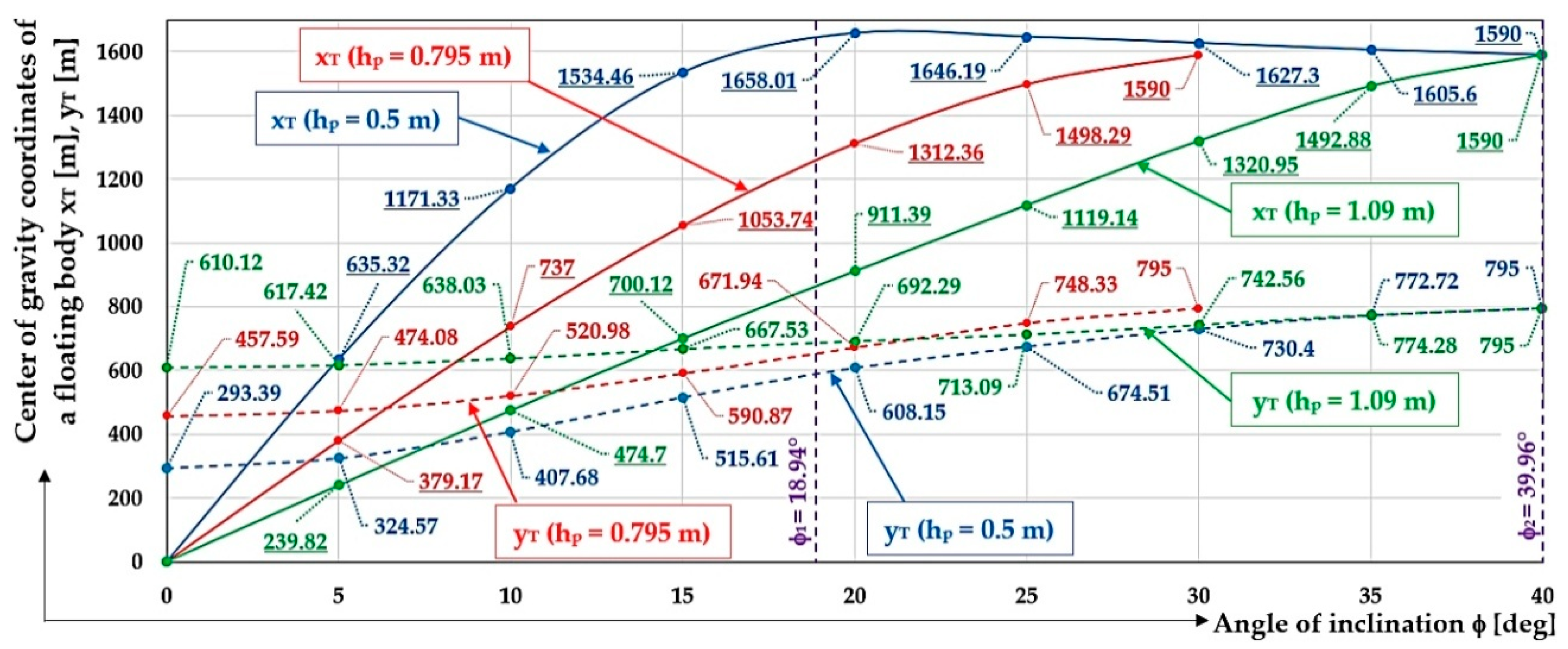
The coordinates of the centre of gravity x T , y T m , m of buoyant force F B N of the floating body during deflection 0 ϕ ϕ 2 d e g at different immersion depths h p m are presented in Figure 16.
In case h p < D 2 m , when the port float is not completely above the water surface, i.e., ϕ < ϕ 1 d e g , the immersion depth of the right float can be v 2 ϕ m and the left float v 1 ϕ m can be expressed according to Equation (51).
v 1 ϕ = t 2 * d 1 ϕ · c o s ϕ   [ m ] ; v 2 ϕ = t 2 * d 2 ϕ · c o s ϕ   [ m ] .
for t 2 * = h p D 2 m .
The area of the submerged surface S 2 t 2 * m 2 , as shown in Figure 14a, of the right cylindrical float can be expressed for ϕ ϕ 1 = 18.94   d e g (16), (18) by Equation (39). The submerged area S 1 t 2 * m 2 , shown in Figure 15b, of the left cylindrical float can be expressed for ϕ ϕ 1 = 18.94   d e g (16) by Equation (46).
The centre of gravity T 1 t 1 * m of the immersed surface S 1 t 2 * m 2 of the left float of the floating body is expressed by Equation (47). The centre of gravity T 2 t 2 *   [ m ] of the immersed surface S 2 t 2 *   [ m 2 ] of the right float of a floating body can be expressed by Equation (40).
The coordinates of the centre of gravity x T 12 , y T m , m of the buoyancy force of the floating body during the first phase of deflection 0 ϕ ϕ 1 at the float immersion depth h p = 500   m m , expressed according to Equations (44) and (49), are given in Table 10.
For h p < D 2 m , when the port float is completely above the water surface, i.e., ϕ 1 ϕ ϕ 2 d e g , the immersion depth of the right float v 2 ϕ m can be expressed by Equation (51).
The area of the submerged surface S 2 t 2 *   [ m 2 ] , shown in Figure 14a, of a right cylindrical float can be expressed for ϕ 1 ϕ ϕ 2 d e g (21) by Equation (39).
The centre of gravity T 2 t 2 *   [ m ] of the immersed surface S 2 t 2 *   [ m 2 ] of the right float of a floating body can be expressed by Equation (40).
The coordinates of the centre of gravity x T 12 , y T m , m of the floating body’s buoyancy force during the second phase of deflection ϕ 1 ϕ ϕ 2 at the float immersion depth h p = 500   m m , expressed according to Equations (44) and (49), are given in Table 11.
For the case h p > D 2 m , where the right float is not completely submerged below the water surface, i.e., ϕ ϕ 1 d e g , the submergence depth of both the right float v 2 ϕ m and the left float v 1 ϕ m can be expressed by Equation (51).
The area content of the submerged surface S 2 t 2 * m 2 , shown in Figure 14a, of a right cylindrical float can be expressed for ϕ ϕ 1 = 18.94   d e g (25) by Equation (39). The submerged area S 1 t 2 * m 2 , shown in Figure 15b, of the left cylindrical float can be expressed for ϕ ϕ 1 = 18.94   d e g (25) by Equation (46).
The centre of gravity T 1 t 1 * m of the immersed surface S 1 t 2 * m 2 of the left float of the floating body is expressed by Equation (47). The centre of gravity T 2 t 2 *   [ m ] of the immersed surface S 2 t 2 *   [ m 2 ] of the right float of the floating body is expressed by Equation (40).
The coordinates of the centre of gravity x T 12 , y T m , m of the buoyant body buoyancy force during the first phase of deflection 0 ϕ ϕ 1 at the float immersion depth h p = 1090   m m , expressed according to Equations (44) and (49), are given in Table 12.
In case h p > D 2 m , when the right float is completely submerged under the water surface, i.e., ϕ 1 ϕ ϕ 2 d e g , the immersion depth of the left float v 1 ϕ m can be expressed by the relation (51).
The area of the submerged surface S 1 t 2 *   [ m 2 ] , shown in Figure 14a, of the left cylindrical float can be expressed for ϕ 1 ϕ ϕ 2 d e g (21) by Equation (46).
The centre of gravity T 1 t 1 *   [ m ] of the immersed surface S 1 t 1 *   [ m 2 ] of the left float of the floating body is expressed by Equation (49).
The coordinates of the centre of gravity x T 12 , y T m , m of the buoyant body buoyancy force during the second phase of deflection ϕ 1 ϕ ϕ 2 at the float immersion depth h p = 1090   m m , expressed according to Equations (44) and (49), are given in Table 13.
The immersion area S 0 m 2 of the entire right float of the floating body is as follows (52):
S 0 = D 2 D 2 D 2 2 y 2 D 2 2 y 2 d x · d y m 2
The 2nd phase begins with the time of total emergence of the left right float ( ϕ = ϕ 1   [ d e g ] ), the right float, and the floating body, and ends with loss of stability ( ϕ = ϕ k   [ d e g ] ).
Since, from the tilt angle ϕ 1 = a s i n D b d e g of the floating body, at immersion depth h p = D 2 m the right float is completely immersed S 2 = S 0 m 2 (Figure 7), the surfaced area of the left float S 1 m 2 acquires (with respect to the initial immersion depth h p = D 2 m ) an area S 1 = S 0 m 2 (Figure 7 shows the floating body is further tilted ϕ > ϕ 1 d e g . The position of the centre of gravity x T 2 ; y T 2 m ; m of the immersed surface S 2   [ m 2 ] of the right float of the floating body can be expressed as shown in Table 2.
Starting from the angle of inclination ϕ 2 d e g (21) of the floating body, the right float is fully submerged S 2 = S 0 m 2 (52) at immersion depth h p < D 2 m . The position of the centre of gravity x T 2 ; y T 2 m ; m of the immersed surface S 2   [ m 2 ] of the right float can be expressed as shown in Table 5.
From the angle of inclination ϕ 2 d e g (28) of the floating body, the right float is fully submerged S 2 = S 0 m 2 (52) at the immersion depth h p > D 2 m . The position of the centre of gravity x T 2 ; y T 2 m ; m of the immersed surface S 2   [ m 2 ] of the right float can be expressed according to Table 8.

3. Results

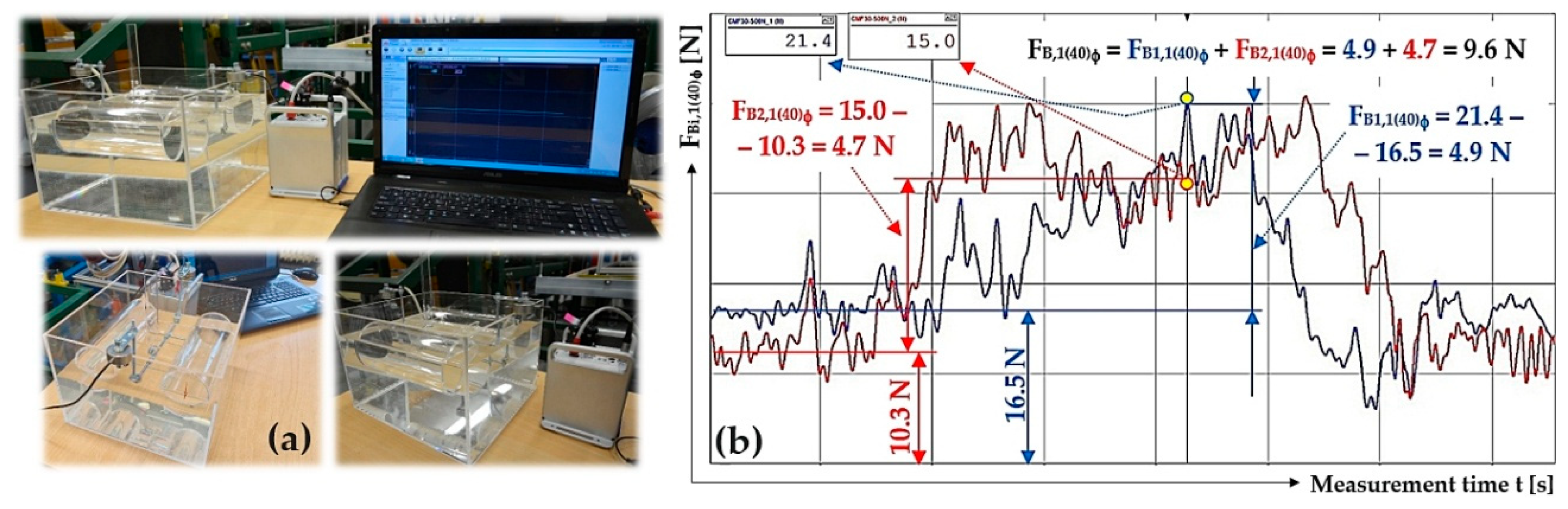
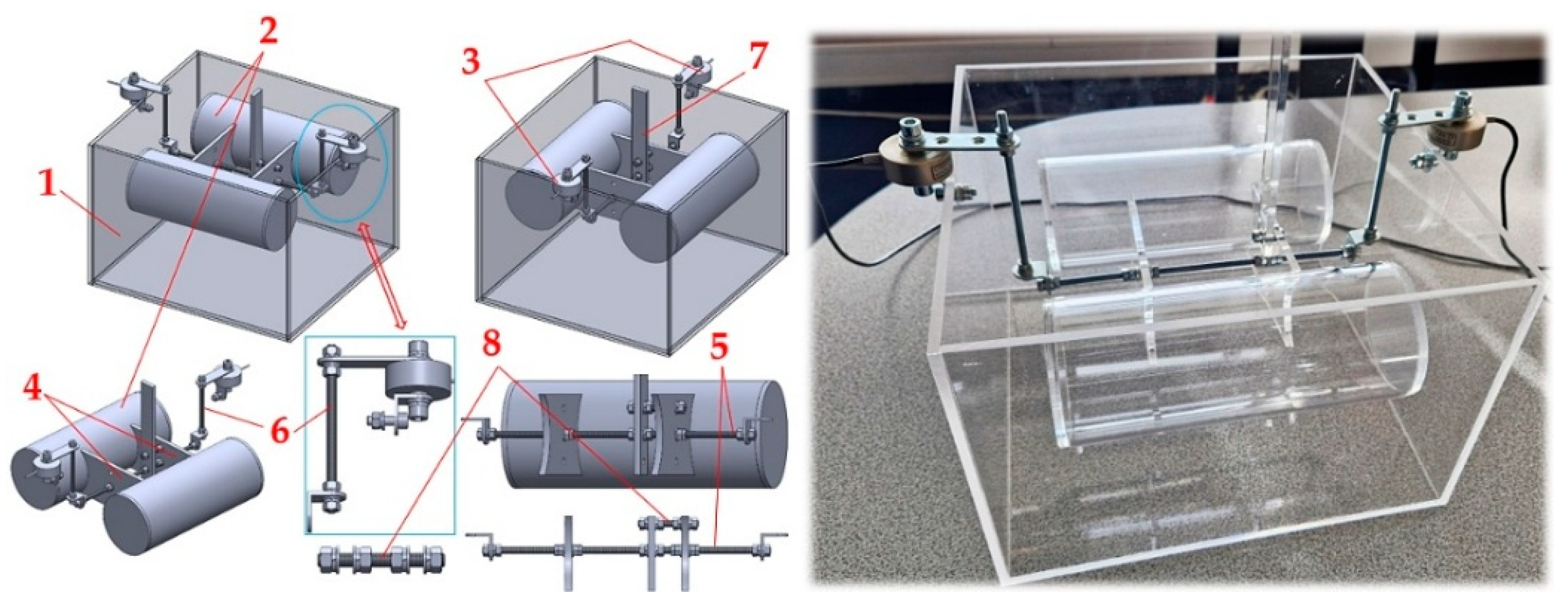
Verification of the buoyancy of the floating body in laboratory conditions was carried out on a test machine, whose 3D model, created in the SolidWorks software environment (version Premium 2012×64, edition SP5.0) [33], is presented in Figure 17. The testing machine consists of a watertight tank (1) and a floating body (2) (which consists of two floats made of PLEXI pipe with 80/72 mm outer/internal diameter [34], length 200 mm and two connecting parts (4)), which is mechanically attached to two force transducers (3), type MCF-100 N [35].
According to Archimedes’ law, the volume V m 3 of the floating body of the mass testing machine m F B k g is immersed below the water surface. The floating body is buoyed by a force equal to the gravity of a fluid of the same volume as the submerged part of the floating body V m 3 .
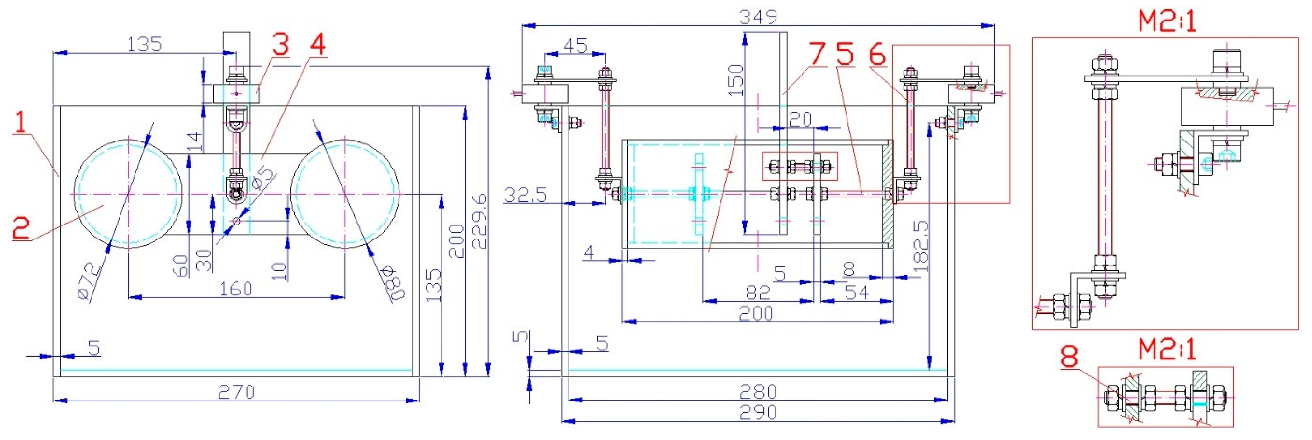
In the equilibrium state of the floating body of the test machine (angle ϕ = 0   d e g ) of mass m F B = 0.746   k g , the frontal surfaces of both floats (diameter D m and length of one float and m ; see Figure 2) are submerged below the water surface by S m 2 . If the floating body is designed so that its centre of gravity lies on the vertical axis of symmetry of the floating body, as shown in Figure 18, then the horizontal axes of both floats of a circular cross-section are parallel to the water surface.
The total immersion area of a floating body S m 2 (53) is given by the sum of the immersion areas of the two floats S = S 1 + S 2 m 2 . Assuming that S 1 = S 2 m 2 can be (with known value S 1 m 2 and the diameter of the float D m ) calculated in the Mathcad software environment (version 14.0.0.163) [32] by the instruction “Given−Find”, the central angle α d e g of the immersed area (circular segment) of one float from relation (54) and the depth h p ( m )   m of the immersion of the float (height of the circular segment) can be determined through Equation (55).
ρ · V = ρ · S · a = m F B S = m F B ρ · a = 0.746 1000 · 0.2 = 37.3 · 10 4   m 2
S 1 = S 2 = 1 2 · D 2 2 · α s i n α m 2 α = 156.46   d e g
S 1 = D 2 2 · a c o s D 2 h p m D 2 D 2 h p m · 2 · h p m · D 2 h p m 2 m 2 h p m = 31.84   m m
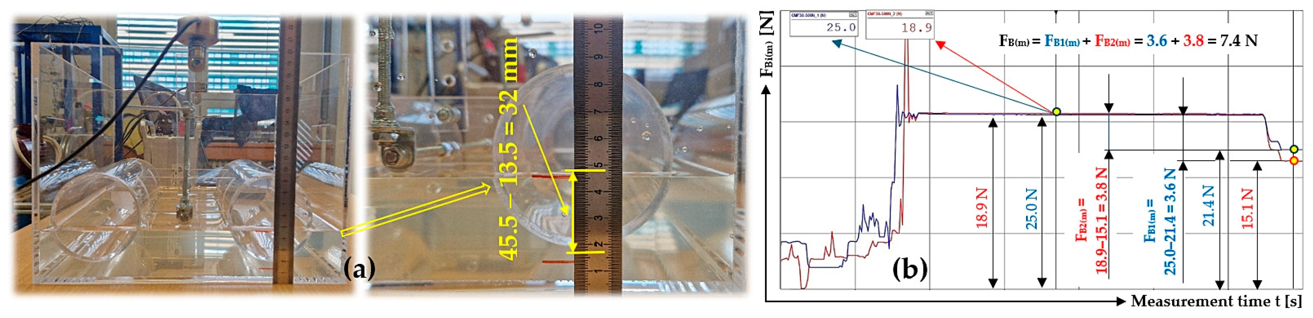
A buoyancy force F B ( m ) N (56) is exerted on the floating body of the test machine, consisting of cylindrical floats of diameter D = 80   m m and length a = 200   m m , at the immersion depth h p m = 31.84   m m ; see Figure 19a,b.
F B m = ρ · S · a · g = 1000 · 37.3 · 10 4 · 20 · 10 3 · g = 7.32   N
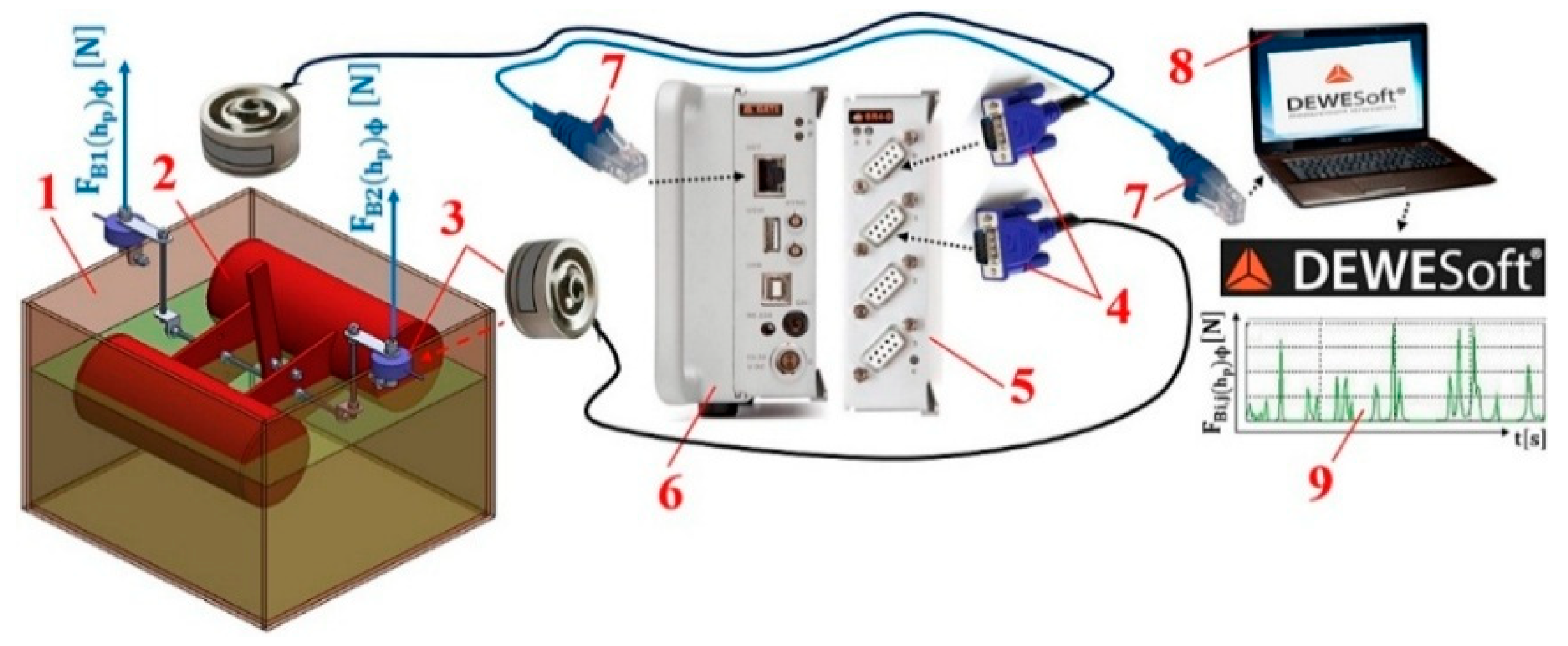
A load sensor cable equipped with a D-Sub plug 4 was plugged into the socket of the measuring module BR4–D 4 [36] of the strain gauge apparatus DS NET during the laboratory measurements; see Figure 20. A PC 8 (ASUS K72JR–TY131 laptop) was connected to the DS NET strain gauge 6 using a network cable with RJ–45 connectors 7 at both ends.
With a known magnitude h p   [ m ] for the floats that are below the water surface in the equilibrium state ( ϕ = 0   d e g ), the floating body was deflected in the longitudinal direction by a known magnitude of angle ϕ   [ d e g ] through PLEXI plate 7. When the floating body was deflected out of its equilibrium state, the magnitudes of the buoyancy forces were detected by force transducers 3; see Figure 20, F B i , j h p ϕ N (where i is the force transducer number and j is the measurement number).
The results of the experimental measurements of the buoyancy force F B i , j h p ϕ N at an immersion depth for the floating body of the testing machine h p = 20   m m below the water surface and the known value of the longitudinal deflection of the floating body from the equilibrium state ϕ d e g are shown in Table 14.
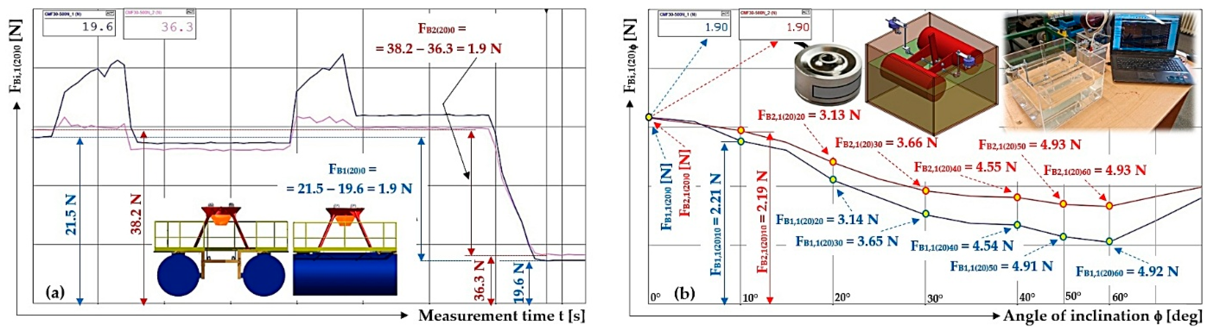
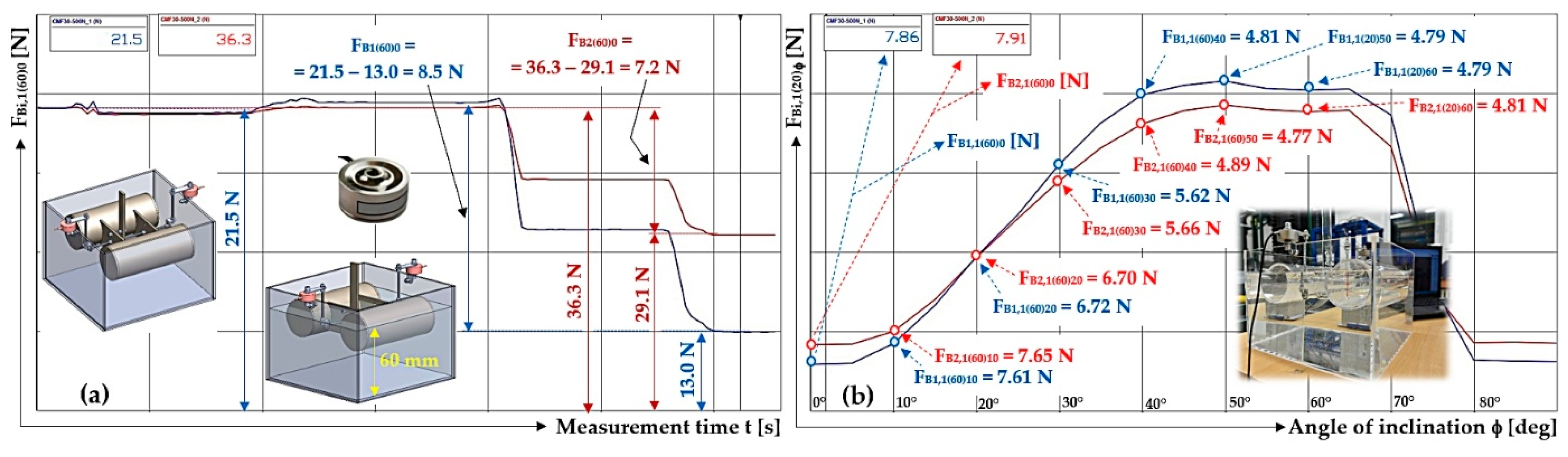
Figure 21a shows the buoyancy force values F B j h p 0 N measured by force sensors MCF-100 N, with floats with a circular cross-section not submerged below the water surface at float submergence depth h p = 20   m m floats and the angle of deflection ϕ = 0   d e g .
Figure 21b shows the buoyancy force values F B i , 1 20 ϕ N measured by force sensors MCF–100 N at an immersion depth of h p = 20   m m for the floats, with gradual deflection of ϕ = 0 ÷ 60   d e g for the floating body of the testing machine.
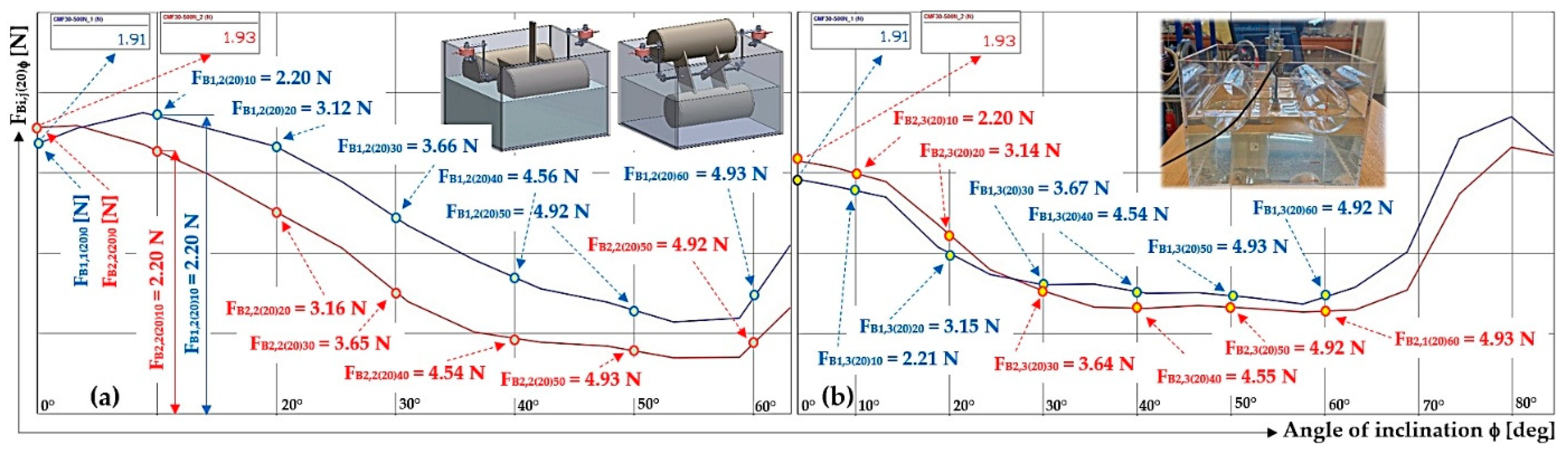
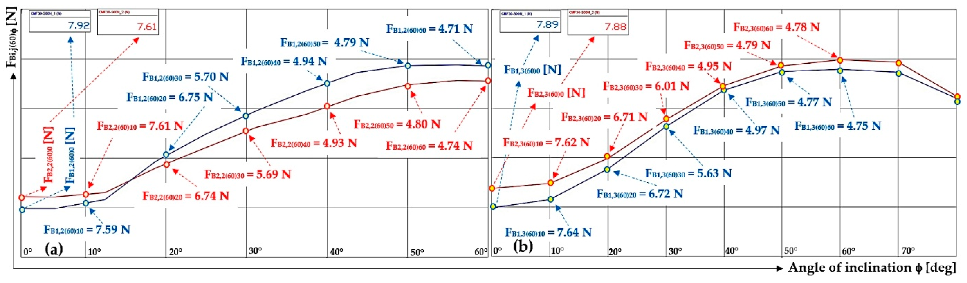
Figure 22 shows the buoyancy force values F B i , j 20 ϕ N measured by force [37] sensors MCF–100 N at the immersion depth h p = 20   m m for the floats, with a gradual deflection of ϕ = 0 ÷ 60   d e g in the floating body of the testing machine.
From measurements repeated three times ( n = 3 ) under the same technical conditions, the arithmetic mean F B i h p ϕ N and the marginal error κ i β , n ϕ   N (57) were calculated according to Student’s distribution [38].
κ i β , n ϕ = t β , n · s ¯   [ N ]
where t β , n is Student’s coefficient (for the chosen risk β = 5 % and the number of measured values n = 3 can be determined according to [38] t β , n = t 5 % , 3 = 4.3 ); s ¯   [ N ] is the standard deviation of the arithmetic mean (58).
s ¯ 5 4 · j = 1 3 F B i , j h p ϕ F B i h p ϕ n · n 1 N
From the measured mean value of the buoyancy force F B h p ϕ N , determined according to Equation (59), the total immersed area of the floats S h p ϕ m 2 on the floating body of the testing machine at immersion depth h p m and deflection angle ϕ d e g of the floating body compared to the equilibrium state can be calculated as follows:
S h p ϕ = F B h p ϕ ρ · a · g m 2
Table 15 shows the total immersed area of the floats S h p ϕ m 2 of the testing machine at the immersion depth h p = 20   m m and deflection angle ϕ d e g from the equilibrium state.
The results of the experimental measurements of the buoyancy force F B i , j h p ϕ N at an immersion depth for the floating body of the testing machine of h p = 40   m m , as well as the known value of longitudinal deflection of the floating body from the equilibrium state ϕ d e g , are shown in Table 16.
Figure 23b shows the buoyancy force values F B i , 1 40 ϕ N measured by force sensors MCF–100 N at an immersion depth of h p = 40   m m below the water surface, with a gradual deflection of ϕ = 0 ÷ 60   d e g for the floating body of the testing machine.
The results of the experimental measurements with the buoyancy force F B i , j h p ϕ N at an immersion depth h p = 60   m m below the water surface and the known value of longitudinal deflection of the floating body from the equilibrium state ϕ d e g are shown in Table 17.
Figure 24a shows the buoyancy force values F B j , 1 60 ϕ N measured by force sensors MCF-100 N, with floats with a circular cross-section not submerged below the water surface at a float submergence depth h p = 60   m m and deflection angle of ϕ = 0   d e g .
Figure 24b shows the buoyancy force values F B i , 1 60 ϕ N measured by force sensors MCF–100 N for floats at an immersion depth of h p = 60   m m below the water surface, with a gradual deflection of ϕ = 0 ÷ 60   d e g for the floating body of the testing machine.
Figure 25 shows the buoyancy force values F B i , j 60 ϕ N measured by force sensors MCF–100 N for floats at an immersion depth of h p = 60   m m below the water surface, with a gradual deflection of ϕ = 0 ÷ 60   d e g for the floating body of the testing machine.
Table 18 shows the total immersed area of the floats S h p ϕ m 2 of the floating body of the testing machine at the immersion depth h p = 60   m m and a deflection angle of ϕ d e g from the equilibrium state.

4. Discussion

The longitudinal and transverse stability of floating belt conveyors using floating bodies with floats of a circular cross-section [28,39] has not been comprehensively and systematically analyzed, as evidenced by the lack of relevant scientific articles and publications in this area.
In the presented paper, two methodological approaches are described to determine the centre of gravity of the displacement of a floating body during longitudinal deflection from the equilibrium state.
The first method (see Section 2.1, Section 2.2 and Section 2.3) is based on the graphical and numerical determination of the centre of gravity of the displacement of the floating body, complemented by the use of 3D modelling tools (e.g., SolidWorks [33] or Inventor). The computationally demanding and time-consuming analytical procedure for determining the centre of gravity of the displacement when the body is deflected from its equilibrium position can be effectively replaced by determining the centre of gravity based on a volume model created in a CAD system environment.
The obtained coordinates of the centre of gravity of displacement x T ; y T m ; m (i.e., the centre of buoyancy force F B N ) at each stage in the deflection of the floating body from the equilibrium state by a known magnitude of angle ϕ d e g , at three immersion depths h p m 0.795 ; 0.5 ; 1.09 , are given in Table 1, Table 2, Table 3, Table 4, Table 5, Table 6, Table 7 and Table 8.
Maximum stability arm value s a = 997.98 · 10 3   m was achieved for cylindrical floats of diameter D = 1.59   m , whose submergence below the water surface reached exactly half the float diameter, i.e., h G = D 2 = 0.795   m , at a heel angle of ϕ = 25   d e g (see Table 1).
Maximum stability arm value s a = 1.24   m was achieved for cylindrical floats of diameter D = 1.59   m whose submergence below the water surface did not exceed half the diameter, e.g., h G < D 2 = 0.5   m , at heel angle of ϕ 19   d e g (see Table 3).
Maximum stability arm size s a = 701.01 · 10 3   m was achieved for cylindrical floats of diameter D = 1.59   m whose submergence below the water surface exceeded half the diameter, e.g., h G > D 2 = 1.09   m , at a heel angle of ϕ 40   d e g (see Table 7).
The second method (see Section 2.4) is based on the analytical determination of the coordinates for the centre of gravity of the displacement of the floating body. The coordinates for the centre of gravity of the displacement are identical to the values of x T , y T m , m , determined by the “first method”.
Table 9 presents the coordinates for the centre of gravity x T 12 , y 12 m , m of the buoyancy force of the floating body during phase 1 of deflection at an immersion depth of h p = 795   m m .
Table 10 presents the coordinates of the centre of gravity x T 12 , y 12 m , m of the buoyancy force of the floating body during phase 1 of deflection, and Table 11 presents the coordinates of the centre of gravity x T 12 , y 12 m , m of the buoyancy force of the floating body during the 2nd phase of deflection, at the depth of immersion h p = 500   m m .
Table 12 presents the coordinates for the centre of gravity x T 12 , y 12 m , m of the buoyancy force of the floating body during phase 1 of deflection, and Table 13 presents the coordinates for the centre of gravity x T 12 , y 12 m , m of the buoyancy force of the floating body during the 2nd phase of the yaw, at the depth of immersion h p = 1090   m m .
The aim of the experimental tests carried out using laboratory equipment (see Figure 23a) was to determine the actual buoyancy force values based on direct measurements using force transducers [35], depending on the angle of inclination ϕ d e g and immersion h p m below the liquid surface [1].
Experimental measurements verified the correctness of the analytical determination of the centre of gravity of the displacement of the floating body during its longitudinal deflection from the equilibrium position.
Based on Figure 21b and Figure 22, the conclusion can be formulated that when the floating body is submerged below the surface by a value exceeding half of the float diameter (circular cross-section), the magnitude of the buoyancy force decreases with increasing angle of inclination.
When the floating body is immersed to half the diameter of the cylindrical floats, the buoyancy force remains constant; see Figure 23b. When a floating body is more or less submerged, the buoyancy force changes with increasing angle of inclination, either decreasing or increasing depending on the specific submergence conditions.
Based on Figure 24b and Figure 25, it can be concluded that when the floating body is submerged below the surface by a value not exceeding half of the float diameter (circular cross-section), the magnitude of the buoyancy force increases with increasing angle of inclination.
Future research in the area of floating conveyor belt buoyancy should also focus on a detailed analysis of the stability loss mechanisms in relation to the transverse stability of the floating body [40]. The key topic is to deepen the understanding of critical states in which a transition from steady-state to unsteady behaviour occurs due to changes in buoyancy distribution and metacentre shifts during transverse deflection of the floating body [41].
Furthermore, the research could be extended through a experimental and numerical modelling of the dynamic response of floating conveyors to external loads, including the effects of waves, uneven loading and changes in embedment. Attention should also be paid to the influence of the geometrical parameters of the floats and their arrangement on the so-called “metacentric height” [2,28], and the overall lateral stability of the system.
Optimization of the structural design to increase the stability margin is also a promising area, especially through modifications to the shape of the floats, their mutual configuration and the weight distribution of the conveyor [21,25]. At the same time, the development of advanced computational methods is recommended [7,18,19,22], which would allow for the reliable prediction of stability limit states in real operating conditions.

5. Conclusions

Floating belt conveyor routes, consisting of serially arranged belt conveyors, the end parts of which are mechanically fixed to floating bodies, are used for the continuous transport of extracted granular materials from the water. This paper focuses on the analytical determination of the centre of gravity of the buoyancy force, the coordinates of which change depending on the longitudinal deflection of the floating body from the equilibrium position, while this body function as the supporting element in individual conveyor belts.
The analysis of the individual phases of deflection of the floating body, consisting of a pair of cylindrical floats with a circular cross-section, showed that the complete immersion of one of the floats occurs at a higher angle of inclination when, in the equilibrium position, floats are immersed to just half of their diameter.
The experimental verification was carried out on a laboratory machine, where the magnitude of the buoyancy force was measured using strain gauges during the gradual deflection of the floating body from the equilibrium position at three defined levels of immersion. The floating body used in the experiment consisted of a pair of cylindrical floats with a circular cross-section with a diameter of 80 mm.
This work provides a systematic methodological procedure for determining the centre of gravity of displacement (centre of buoyancy) when a floating body deviates from the equilibrium position, together with a methodology for calculating the stability arm as a key parameter for assessing the buoyancy and lateral stability of a structure.
Based on laboratory measurements, the behaviour of the buoyancy force as a function of the immersion depth was further quantified. It was found that the buoyancy force remains constant during deflection only at an immersion corresponding to half the float’s diameter. At lower immersion, the buoyancy force increases with increasing bank angle, while at higher drafts, its magnitude decreases with increasing bank.

Supplementary Materials

The following supporting information can be downloaded at: https://www.mdpi.com/article/10.3390/machines14050576/s1.

Author Contributions

Conceptualization, L.H.; methodology, L.H.; software, L.H. and L.K.; validation, L.H., P.K. and L.K.; formal analysis, L.H.; investigation, L.H.; resources, L.H. and P.K.; data curation, L.H.; writing—original draft preparation, L.H.; writing—review and editing, L.H.; visualization, L.H.; supervision, L.H.; project administration, L.K.; funding acquisition, L.H. All authors have read and agreed to the published version of the manuscript.

Funding

This research was funded by The Ministry of Education Youth and Sports (MEYS, MŠMT in Czech), grant number SP2026/001. The APC was funded by MSM: SV20266640 Specifický výzkum VŠB-TUO.

Data Availability Statement

Measured data of buoyancy forces F B i , j h p ϕ N (force sensors ESM30–100N [35]), listed in Table 14, Table 16 and Table 17 and processed using DEWESoft X software (2024.5 RELEASE-241202 64-bit), can be provided upon request after prior written agreement in *.XLSX (Microsoft Excel) format or in *.DXD (DEWESOFT X [37]).

Acknowledgments

I would like to express my sincere gratitude to all collaborators who contributed to this research by providing intellectual support, technical assistance, and specialized equipment. I also wish to thank VSB–Technical University of Ostrava for their financial support. This work has been supported by The Ministry of Education, Youth and Sports of the Czech Republic from the Specific Research Project SV 340664 (SP2026/001).

Conflicts of Interest

The authors declare no conflicts of interest. The funders had no role in the design of the study; in the collection, analyses, or interpretation of data; in the writing of the manuscript; or in the decision to publish the results.

Nomenclature

a m length of the floats
D [ m ] diameter of the circular float
F B N buoyancy force
F B i , j h p ϕ N measurement buoyancy force
G F B N gravitational force of the body
h p m draught
h T m distance of the point of application of the gravitational force
S m 2 submerged plan area of the floats
S 1 [ m 2 ] sumberged area of the left float
S 2 [ m 2 ] submerged area of the right float
s ¯ [ N ] standard deviation of the arithmetic mean
t m ength of the chord of a circular segment
t β , n Student’s coefficient
v [ m ] sagitta of a circular segment
V p [ m 3 ] total volume of the submerged parts of the two floats
x T , y T m , m centre of gravity
α d e g central angle of a circular segment
ϕ d e g angle of deviation of a floating body from the equilibrium position
ρ k g · m 3 density of water

References

  1. Hrabovsky, L. Pásové Dopravní Trasy ve Vodních Pískovnách, (In English: Belt Conveyor Systems in Sand and Gravel Quarries with Water-Filled Pits), 1st ed.; VSB—Technical University of Ostrava: Ostrava, Czech Republic, 2010; p. 156. ISBN 8024823136. Available online: https://ceskadigitalniknihovna.cz/view/uuid:ba286a00-7495-11e8-87bd-005056827e52?page=uuid:cb42f540-8a06-11e8-9690-005056827e51&source=mzk (accessed on 18 March 2021).
  2. Zadnik, B. Stavba a Opravy Lodí, (In English: Shipbuilding and Ship Repair), 1st ed.; NADAS: Praha, Czech Republic, 1980; p. 461. [Google Scholar]
  3. Floating Conveyor Belts. Available online: https://prosand.cz/stroje/plovouci-dopravnikove-pasy (accessed on 18 March 2021).
  4. Floating Conveyor Belts. Available online: https://www.ffa-fiebig.de/index.php/en/belt-conveyors/floating-belt-conveyors (accessed on 20 November 2025).
  5. Vassalos, D.; Paterson, D. Towards unsinkable ships. Ocean Eng. 2021, 232, 109096. [Google Scholar] [CrossRef]
  6. Grochowalski, S.; Pawlowski, M. The safety of Ro-Ro vessels in the light of the probabilistic concept for standardizing unsinkability. Int. Shipbuild. Prog. 1981, 28, 63–72. [Google Scholar] [CrossRef]
  7. Hrabovsky, L.; Nenicka, P.; Fries, J. Laboratory machine verification of force transmission provided by friction acting on the drive drum of a conveyor belt. Machines 2023, 11, 544. [Google Scholar] [CrossRef]
  8. Kassem, A.H. The Legal Aspects of Seaworthiness: Current Law and Development. Doctoral Dissertation, Swansea University, Swansea, UK, 13 March 2006. [Google Scholar]
  9. Chamlee, G.H. The absolute warranty of seaworthiness: A history and comparative study. Mercer Law Rev. 1973, 24, 519. [Google Scholar]
  10. Padovan, A.V. The elements of seaworthiness in the context of marine insurance revisited. In Proceedings of the 4th International Scientific Conference on Maritime LAW–ISCML Split 2023: Modern Challenges of Marine Navigation, Split, Croatia, 13–14 April 2023; pp. 101–122. Available online: https://iscml-split.com/wp-content/uploads/2024/04/zbornik_pomorsko-pravo_2023.pdf (accessed on 6 May 2023).
  11. So, L.K.; Sooksripaisarnkit, P. Seaworthiness and autonomous ships: Legal implications in the 21st century. Aust. N. Z. Marit. Law J. 2021, 35, 21–30. [Google Scholar]
  12. Girvin, S. The Obligation of Seaworthiness: Shipowner and Charterer. In Proceedings of the 25th Pan–American Conference of Naval Engineering, COPINAVAL, Panama City, Panama, 16–19 October 2017. [Google Scholar] [CrossRef]
  13. Gonzalez, M.M.; Sobrino, P.C.; Alvarez, R.T.; Casas, V.D.; Lopez, A.M.; Pena, F.L. Fishing vessel stability assessment system. Ocean Eng. 2012, 41, 67–78. [Google Scholar] [CrossRef]
  14. Umar, A.; Ahmad, S.; Datta, T.K. Stability analysis of a moored vessel. J. Offshore Mech. Arct. Eng. 2004, 126, 164–174. [Google Scholar] [CrossRef]
  15. Leira, B.J.; Berntsen, P.I.B.; Aamo, O.M.; Sorensen, A.J. Reliability-based dynamic position control of floating vessels: A numerical and experimental study. Ships Offshore Struct. 2009, 4, 207–214. [Google Scholar] [CrossRef]
  16. Halyna, D. Vessel dynamic positioning system mathematical model. In Proceedings of the VIII International Science Conference—Modern Technologies of Human Development, Bordeaux, France, 6–8 November 2023; Available online: https://lib.udau.edu.ua:8443/server/api/core/bitstreams/6e7388ca-eda5-4aa2-9e03-db68b13bf9ae/content (accessed on 11 April 2025).
  17. Michalik, P.; Dobransky, J.; Hrabovsky, L.; Petrus, M. Assessment of the Manufacturing Possibility of Thin-Walled Robotic Portals for Conveyor Worklace. Adv. Sci. Technol. Res. J. 2018, 12, 338–345. [Google Scholar] [CrossRef]
  18. Francescutto, A.; Papanikolaou, A.D. Buoyancy, stability, and subdivision: From Archimedes to SOLAS 2009 and the way ahead. Proc. Inst. Mech. Eng. Part M J. Eng. Marit. Environ. 2011, 225, 17–32. [Google Scholar] [CrossRef]
  19. Ruponen, P. Principles of Ship Buoyancy and Stability, 1st ed.; Aalto University: Helsinki, Finland, 2021; p. 174. Available online: https://aaltodoc.aalto.fi/server/api/core/bitstreams/a9de4444-baa0-4009-96a6-88a96b8e669a/content (accessed on 27 June 2022).
  20. Martic, I.; Degiuli, N.; Grlj, C.G.; Borcic, K.; Andrisic, J.; Lalovic, I. Impact of the longitudinal center of buoyancy on the total resistance of a passenger ship. J. Mar. Sci. Eng. 2024, 12, 1749. [Google Scholar] [CrossRef]
  21. Spyrou, K.J. The stability of floating regular solids. Ocean Eng. 2022, 257, 111615. [Google Scholar] [CrossRef]
  22. Cao, X.; Zhou, Z.; Zhang, H.; Zhang, N. A review on the stability of towed floating bodies during wet towing operations. Ocean Eng. 2025, 340, 122449. [Google Scholar] [CrossRef]
  23. Shames, I.H. Mecánica de Fluidos, 3rd ed.; Faculty of Engineering and Applied Science: New York, NY, USA, 2008; pp. 154–196. Available online: https://www.academia.edu/8066544/Mecanica_de_fluidos_shames (accessed on 20 November 2024).
  24. Streeter, V.A. Mecánica de los Fluidos, 1st ed.; McGraw-Hill Interamericana, S.A.: Ciudad de México, Mexico, 2000; p. 747. Available online: https://www.google.cz/books/edition/Mecánica_de_los_fluidos/CMsK0QEACAAJ?hl=cs (accessed on 3 January 2009).
  25. Atua, K.; Ayyub, B.M. Reliability analysis of transverse stability of surface ships. Nav. Eng. J. 2009, 109, 129–140. [Google Scholar] [CrossRef]
  26. Haddara, M.R.; Wishahy, M.; Wu, X. Assessment of ship’s transverse stability at sea. Ocean Eng. 1994, 21, 781–800. [Google Scholar] [CrossRef]
  27. Megel, J.; Kliava, J. Metacenter and ship stability. Am. J. Phys. 2010, 78, 737–747. [Google Scholar] [CrossRef]
  28. Hrabovsky, L. Příčná stabilita plovoucího tělesa válcového tvaru plováků (In English: Transverse stability of a floating body with cylindrical-shaped floats). Perner’s Contacts 2010, 5, 85–94. Available online: https://pernerscontacts.upce.cz/index.php/perner/article/view/942 (accessed on 13 July 2010).
  29. Hrabovsky, L. Podélná stabilita plovoucího tělesa válcového tvaru plováků–1. fáze (In English: Longitudinal stability of a floating body with cylindrical-shaped floats—Phase 1). Perner’s Contacts 2010, 5, 84–94. Available online: https://pernerscontacts.upce.cz/index.php/perner/article/view/997 (accessed on 14 July 2010).
  30. Lazecky, P. Stabilita Plovoucího Dopravníku s Koncovými Plováky (In English: Stability of Floating Conveyor with End Floats). Bachelor’s Thesis, VSB—Technical University of Ostrava, Ostrava, Czech Republic, 2012. Available online: http://hdl.handle.net/10084/93886 (accessed on 16 August 2012).
  31. Livecka, E.; Melzer, L. Vodní Bagrování (In English: Water Dredging), 1st ed.; SNTL: Brno, Czech Republic, 1964; p. 302. Available online: https://vufind.mzk.cz/Record/svkpk.PNA01-000303323 (accessed on 13 July 2020).
  32. Mathcad 14.0—User’s Guide. Available online: https://www.scribd.com/doc/3239532/Mathcad-14-Users-Guide (accessed on 8 May 2007).
  33. Pagac, M. Učebnice SolidWorks (In English: SolidWorks Textbook); Vydavatelství Nová Media s. r. o.: Prague, Czech Republic, 2020; p. 416. ISBN 978-80-270-0918-3. Available online: https://eshop.solidvision.cz/ucebnice-solidworks-2/ (accessed on 22 November 2020).
  34. PLEXIGLAS® Trubky a Tyče Technický List (In English: LEXIGLAS® Tubes and Rods—Technical Data Sheet). Available online: https://www.zenit.cz/public/media/Plasty/Zenit_Technicky_List_Plasty_Plexiglas_trubky_tyce.pdf?_ga=2.46977383.1190389475.1773304708-1782010313.1773304708 (accessed on 13 August 2025).
  35. Tenzometrický Snímač Síly EMS30 (In English: EMS30 Strain Gauge Force Sensor). Available online: https://www.emsyst.sk/products/force-sensors/standard/files/EMS30_sk.pdf (accessed on 28 July 2025).
  36. Technical Reference Manual DS–NET V20–1. Available online: https://d36j349d8rqm96.cloudfront.net/3/6/Dewesoft-DS-NET-Manual-EN.pdf (accessed on 17 November 2016).
  37. User Manual Getting Started with Dewesoft® V21–1. Available online: https://downloads.dewesoft.com/manuals/dewesoftx-getting-started-manual-en.pdf (accessed on 7 January 2021).
  38. Madr, V.; Knejzlik, J.; Kopecny, I.; Novotny, I. Fyzikální Měření (In English: Physical Measurement); SNTL: Prague, Czech Republic, 1991; p. 304. ISBN 80-03-00266-4. [Google Scholar]
  39. Hrabovsky, L.; Maslaric, M. Device designed for detection and setting the required tensile force in ropes. Adv. Sci. Technol. Res. J. 2018, 12, 200–206. [Google Scholar] [CrossRef]
  40. Thompson, J.M.T.; Rainey, R.C.T.; Soliman, M.S. Ship stability criteria based on chaotic transients from incursive fractals. Philos. Trans. R. Soc. Lond. Ser. A Phys. Eng. Sci. 1990, 332, 149–167. [Google Scholar] [CrossRef]
  41. Surendran, S.; Reddy, J.V.R. Numerical simulation of ship stability for dynamic environment. Ocean Eng. 2003, 30, 1305–1317. [Google Scholar] [CrossRef]
Figure 1. Floating belt conveyor. I—floating body; II—belt conveyor; 1—turntable structure; 2—float of a circular cross-section.
Machines 14 00576 g001
Figure 2. Floating body of a conveyor belt with circular floats.
Machines 14 00576 g002
Figure 4. (a) The area of immersion of the left S 1 m 2 float and right float S 2 m 2 at deflection ϕ d e g of the floating body; (b) coordinates y T 2 m of the centre of gravity T 2 of the right float.
Machines 14 00576 g004
Figure 5. Arm stability s a   m of a floating body deflected from equilibrium by an angle of ϕ d e g .
Machines 14 00576 g005
Figure 6. Stability arm size s a   m at deflection ϕ d e g of the floating turn from equilibrium at h p = 795   m m .
Machines 14 00576 g006
Figure 7. 2D phase of floating body deflection from the equilibrium state ϕ 1 ϕ ϕ k d e g .
Machines 14 00576 g007
Figure 8. Displacement of the floating body from the equilibrium state during phase 1, when the floats (a) h p < D 2 [ m ] and (b) h p > D 2 [ m ] are submerged.
Machines 14 00576 g008
Figure 9. Total immersion of the (a) left float ϕ = ϕ 1 d e g and (b) right float ϕ = ϕ 2 d e g of the floating body at h p < D 2 [ m ] .
Machines 14 00576 g009
Figure 10. Stability arm size s a   m at deflection ϕ d e g of the floating turn from equilibrium at h p = 500   m m .
Machines 14 00576 g010
Figure 13. Deflection of the floating turntable by an angle ϕ   [ d e g ] (a) defined by Equation (32); (b) definition of the intersection distance d 2 ( ϕ ) [m] from the origin of the coordinate system.
Machines 14 00576 g013
Figure 14. Right float of a floating body out of equilibrium, where water level (a) does not exceed the centre C2 of the float and (b) exceeds the centre C2 of the float.
Machines 14 00576 g014
Figure 15. Left float of a floating body out of equilibrium at water level (a) over the centre C 1 of the left float; (b) water level exceeds the centre C 1 of the left float; (c) a representation of the vectors.
Machines 14 00576 g015
Figure 16. Coordinates of the centre of gravity x T , y T m , m buoyancy forces of the floating body during deflection 0 ϕ ϕ 2 at immersion depth h p   m .
Machines 14 00576 g016
Figure 17. 3D model of a laboratory device used to determine the buoyancy of a floating body. 1—tank; 2—floating body; 3—force transducer; 4—float connecting part; 5—axis; 6—connecting assembly of axis with force transducer; 7—PLEXI plate; 8—connecting element.
Machines 14 00576 g017
Figure 18. Basic dimensions of the testing machine. 1—tank; 2—floating body; 3—force transducer [35]; 4—float connecting part; 5—axis; 6—connecting assembly of axis with force transducer; 7—PLEXI plate; 8—connecting element.
Machines 14 00576 g018
Figure 19. (a) Plunging h p m m of the floating body by its own mass m F B k g ; (b) buoyancy force F B m N of a floating body by its own mass m F B k g .
Machines 14 00576 g019
Figure 20. Measurement chain using DS NET to sense tensile forces F B i , j h p ϕ   [ N ] . 1—tank; 2—floating body; 3—force sensor [35]; 4—D–Sub plug; 5—measuring module; 6—gateway module DS GATE; 7—network cable; 8—laptop; 9—software DEWESoft X2 SP5 [37].
Machines 14 00576 g020
Figure 21. Measured buoyancy force waveform (a) F B j h p 0 N of the non-immersed and immersed h p = 20   m m floating body; (b) F B i , 1 20 ϕ N when submerged h p = 20   m m and deflection ϕ = 0 ÷ 60   d e g of the floating body from the equilibrium position.
Machines 14 00576 g021
Figure 22. Measured buoyancy force during deflection of ϕ = 0 ÷ 60   d e g of the floating body from the equilibrium position: (a) F B i , 2 20 ϕ N ; (b) F B i , 3 20 ϕ N .
Machines 14 00576 g022
Figure 23. (a) The testing machine; (b) measurement of the buoyancy force during a deflection of ϕ = 0 ÷ 60   d e g of the floating body from the equilibrium position F B i , 2 40 ϕ N .
Machines 14 00576 g023
Figure 24. Measured buoyancy force waveform (a) F B j h p 0 N of the non-immersed and immersed h p = 60   m m floating body; (b) F B i , 1 60 ϕ N when submerged at h p = 60   m m with a deflection of ϕ = 0 ÷ 60   d e g of the floating body from the equilibrium position.
Machines 14 00576 g024
Figure 25. Measured buoyancy force during a deflection of ϕ = 0 ÷ 60   d e g of the floating body from the equilibrium position (a) F B i , 2 60 ϕ N ; (b) F B i , 3 60 ϕ N .
Machines 14 00576 g025
Table 1. Coordinates of the centre of gravity x T , y T m , m of the buoyant force F B N of the floating body during phase 1 of deflection 0 ϕ ϕ 1 at the immersion depth of h p = 795   m m .
b = 3.18 m; D = 1.59 m; h G = 1.6 m; h p = 0.795 m
ϕ d e g 051015202530 = ϕ 1
x T 10 3 · m 0379.177371053.741312.361498.291590
x T · c o s ϕ 0377.73725.801017.831233.221357.911376.98
y T 457.59474.08520.98590.87671.94748.33795
y T · s i n ϕ 041.3290.47152.93229.82316.26397.50
h G · s i n ϕ 0139.45277.84414.11547.23676.19800
s a   10279.60538.43756.65915.80997.98974.48
S 1 10 4 · m 2 9927.837735.655627.753689.872013.25708.50974.48
S 2 9927.8312,120.0014,227.9116,165.7817,842.4019,147.1519,855.65
S19,855.65
V 1 10 6 · m 3 3,971,130.193,094,260.272,251,098.181,475,948.36805,300.66283,401.910
V 2 3,971,130.194,848,000.115,691,162.216,466,312.037,136,959.727,658,858.487,942,260.39
V7,942,260.39
b = 3.18 m; D = 1.59 m; h G = 2.0 m
h G · s i n ϕ 10 3 · m 0174.31347.30517.64684.04845.241000
s a 10244.73468.97653.12778.99828.93774.48
b = 3.18 m; D = 1.59 m; h G = 2.5 m
h G · s i n ϕ 10 3 · m 0217.89434.12647.05855.051056.551250
s a 10201.16382.15523.72607.98617.62524.48
1 See Figure 6.
Table 2. Coordinates of the centre of gravity x T , y T m , m of the buoyant force F B N of the floating body during phase 2 of deflection ϕ 1 ϕ ϕ k d e g at the immersion depth of h p = 795   m m .
b = 3.18 m; D = 1.59 m; h G = 1.6 m; h p = 0.795 m
ϕ d e g 3540455055606563.15 = ϕ k
x T 10 3 · m 1590
x T · c o s ϕ 1302.451218.011124.301022.03911.99795.00671.96718.13
y T 795
y T · s i n ϕ 455.99511.15562.15609.01651.23688.49720.51709.29
h G · s i n ϕ 917.721028.461131.371225.671310.641385.641450.091427.51
s a   1840.72700.57555.08405.37252.5797.85−57.610
S 2 19,855.65
V 10 6 · m 3 7,942,260.39
b = 3.18 m; D = 1.59 m; h G = 2.0 m
ϕ d e g 354045505552.84 = ϕ k
h G · s i n ϕ 10 3 · m 1147.151285.581414.211532.091683.301593.9
s a   2611.29443.45272.2498.95−75.090
b = 3.18 m; D = 1.59 m; h G = 2.5 m
ϕ d e g 35404543.00 = ϕ k
h G · s i n ϕ 10 3 · m 1433.941606.971767.771705.00
s a   3324.50112.06−81.320
s a = 0   m for ϕ k d e g = 1 63.15; 2 52.84; 3 43.00; see Figure 6.
Table 3. Coordinates of the centre of gravity x T , y T m , m of the buoyant force F B N of the floating body during phase 1 of deflection 0 ϕ ϕ 1 at the immersion depth of h p = 500   m m .
b = 3.18 m; D = 1.59 m; h G = 1.6 m; h p = 0.5 m
ϕ d e g 0510152018.94 = ϕ 1   2
x T 10 3 · m 0635.321171.331534.461658.011659.32
x T · c o s ϕ 0632.901153.531482.171558.021569.48
y T 293.39324.57407.68515.62608.15593.00
y T · s i n ϕ 028.2970.79133.45208.00192.47
h G · s i n ϕ 0139.45277.84414.11547.23519.32
s a   10521.74946.491201.521218.791242.63
S 1 10 4 · m 2 5347.313407.811753.74510.2100
S 2 5347.317474.359698.6011931.8214,085.9613,640.31
S10,694.6110,882.1711,452.3412,442.02
V 1 10 6 · m 3 2,138,922.781,363,125.54701,497.43204,081.8200
V 2 2,138,922.782,989,741.693,879,438.754,772,727.825,634,383.675,456,122.06
V4,277,845.564,352,867.234,580,936.184,976,809.645,634,383.675,456,122.06
b = 3.18 m; D = 1.59 m; h G = 2.0 m; h p = 0.5 m
ϕ d e g 0510152018.94 = ϕ 1 2
h G · s i n ϕ 10 3 · m 0174.31347.3517.64684.04649.16
s a   10486.88877.031097.991081.981112.80
b = 3.18 m; D = 1.59 m; h G = 2.5 m; h p = 0.5 m
ϕ d e g 0510152018.94 = ϕ 1   2
h G · s i n ϕ 10 3 · m 0217.89434.12647.05855.05811.44
s a   10443.30790.21968.58910.97950.51
1 See Figure 10; 2 see Table 3.
Table 4. Coordinates of the centre of gravity x T , y T m , m of the buoyancy force F B N of the floating body during the 2nd phase of deflection ϕ 1 ϕ ϕ 2   d e g at the immersion depth h p = 500   m m .
b = 3.18 m; D = 1.59 m; h G = 1.6 m; h p = 0.5 m
ϕ d e g 2530354039.96 = ϕ 2  1
x T 10 3 · m 1646.191627.301605.6015901590
x T · c o s ϕ 1491.951409.281315.231218.011218.72
y T 674.51730.40772.72795795
y T · s i n ϕ 285.06365.20443.21511.02510.59
h G · s i n ϕ 676.19800.00917.721028.461027.60
s a   21100.83974.48840.72700.57701.71
S 1 10 3 · m 2 0
S 2 16,071.3517,792.4819,133.2919,855.6519,855.65
V 1 10 6 · m 3 0
V 2 = V 6,428,540.837,116,990.817,653,314.247,942,260.397,942,260.39
b = 3.18 m; D = 1.59 m; h G = 2.0 m; h p = 0.5 m
ϕ d e g 2530354039.96 = ϕ 2 1
h G · s i n ϕ 10 3 · m 845.2410001147.151285.581284.51
s a   2931.78774.48611.29443.45444.81
b = 3.18 m; D = 1.59 m; h G = 2.5 m; h p = 0.5 m
ϕ d e g 2530354039.96 = ϕ 2 1
h G · s i n ϕ 10 3 · m 1056.551250.001433.941606.97
s a   2720.47524.48324.50122.06123.68
1 See (18); 2 see Figure 10.
Table 5. Coordinates of the centre of gravity x T , y T m , m of the buoyancy force F B N of the floating body during the 3rd phase.
b = 3.18 m; D = 1.59 m; h G = 1.6 m; h p = 0.5 m
ϕ d e g 455055606563.15   = ϕ k   1
x T 10 3 · m 1590
x T · c o s ϕ 1124.301022.03911.99795.00671.96718.13
y T 795
y T · s i n ϕ 562.15609.01651.23688.49720.51709.29
h G · s i n ϕ 1131.371225.671310.641385.641450.091427.51
s a   1555.08405.37252.5797.85−57.610
S 1 10 3 · m 2 0
S 2 19,855.65
V 1 10 6 · m 3 0
V 2 = V 7,942,260.39
b = 3.18 m, D = 1.59 m, h G = 2.0 m, h p = 0.5 m
ϕ d e g 45505552.84   = ϕ k   1
h G · s i n ϕ 10 3 · m 1414.211532.091638.301593.90
s a   1272.2498.95−75.090
b = 3.18 m; D = 1.59 m; h G = 2.5 m; h p = 0.5 m
ϕ d e g 4543.00   = ϕ k   1
h G · s i n ϕ 10 3 · m 1767.771705.00
s a   1−81.320
1 See Figure 10.
Table 7. Coordinates of the centre of gravity x T , y T m , m of the buoyancy force F B N of the floating body during the 2nd phase of deflection ϕ 1 ϕ ϕ 2   d e g at immersion depth h p = 1090   m m .
b = 3.18 m; D = 1.59 m; h G = 1.6 m; h p = 1.09 m
ϕ d e g 2530354039.96 = ϕ 2 2
x T 10 3 · m 1119.141320.951492.8815901590
x T · c o s ϕ 1014.291143.981222.901218.011218.72
y T 713.09742.56774.28795795
y T · s i n ϕ 301.36371.28444.11511.02510.59
h G · s i n ϕ 676.19800.00917.721028.461027.60
s a   1639.46715.26749.28700.57701.71
S 1 10 3 · m 2 3784.302063.17722.3700
S 2 19,855.65
V 1 10 6 · m 3 1,513,719.56825,269.57288,946.1500
V 2 7,942,260.39
V9,455,979.957,942,260.398,231,206.547,942,260.397,942,260.39
b = 3.18 m; D = 1.59 m; h G = 2.0 m; h p = 1.09 m
ϕ d e g 2530354039.96 = ϕ 2   1
h G · s i n ϕ 10 3 · m 845.2410001147.151285.581284.51
s a   1470.41515.26519.82444.45444.81
b = 3.18 m; D = 1.59 m; h G = 2.5 m; h p = 1.09 m
ϕ d e g 2530354039.96 = ϕ 2   1
h G · s i n ϕ 10 3 · m 1056.551250.001433.941606.971605.63
s a   1259.10265.26233.06122.06123.68
1 See Figure 12; 2 see Figure 11b.
Table 8. Coordinates of the centre of gravity x T , y T m , m of the buoyancy force F B N of the floating body during the 3rd phase of deflection ϕ 2 ϕ ϕ k   d e g at immersion depth h p = 1090   m m .

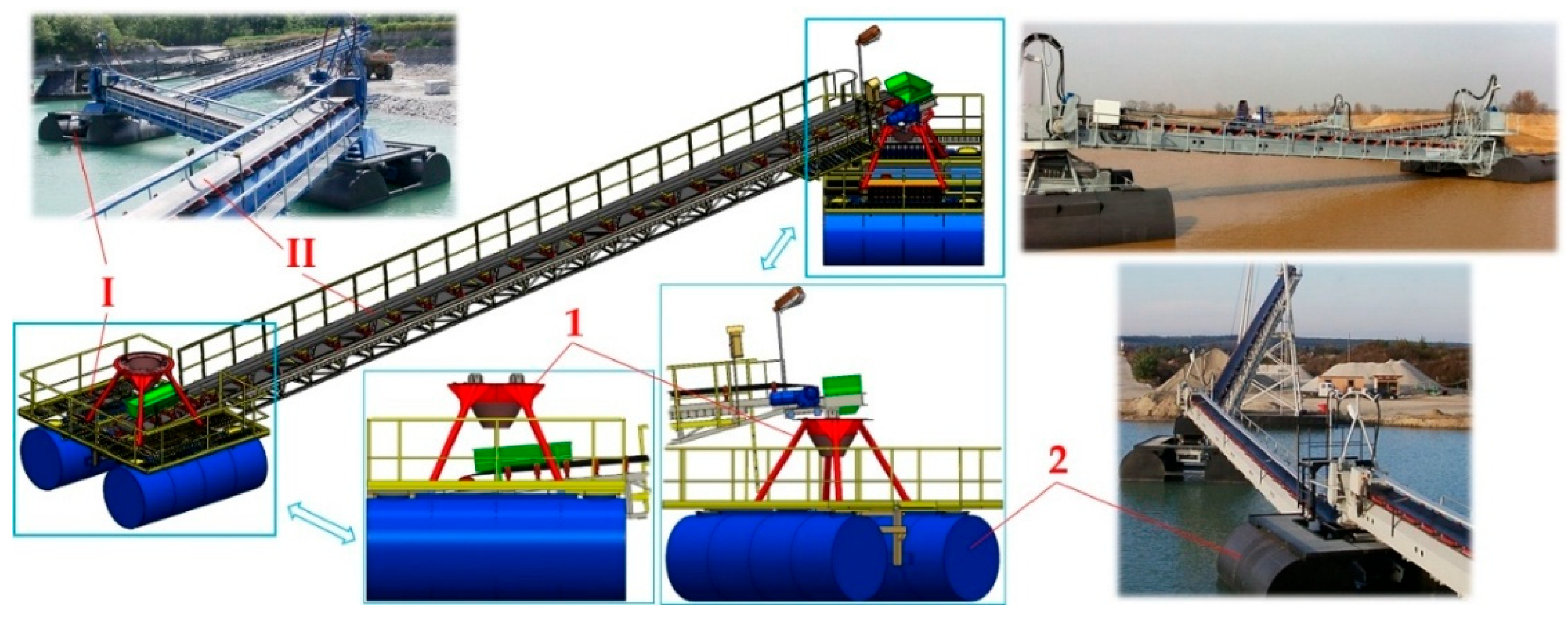
b = 3.18 m; D = 1.59 m; h G = 1.6 m; h p = 1.09 m
ϕ d e g 455055606563.15   = ϕ k   1
x T 10 3 · m 1590
x T · c o s ϕ 1124.301022.03911.99795.00671.96718.13
y T 795
y T · s i n ϕ 562.15609.01651.23688.49720.51709.29
h G · s i n ϕ 1131.371225.671310.641385.641450.091427.51
s a   1555.08405.37252.5797.85−57.610
S 1 10 3 · m 2 0
S 2 19,855.65
V 1 10 6 · m 3 0
V 2 = V 7,942,260.39
b = 3.18 m; D = 1.59 m; h G = 2.0 m; h p = 1.09 m
ϕ d e g 45505552.84   = ϕ k   1
h G · s i n ϕ 10 3 · m 1414.211532.091638.31593.90
s a   1272.2498.95−75.090
b = 3.18 m; D = 1.59 m; h G = 2.5 m; h p = 0.5 m
ϕ d e g 4543.00   = ϕ k 1
h G · s i n ϕ 10 3 · m 1767.771705.00
s a   1−81.320
1 See Figure 12.
Table 9. Coordinates of the centre of gravity x T 12 , y T m , m of the buoyancy force of the floating body during phase 1 of deflection at the immersion depth h p = 795   m m .
b = 3.18 m; D = 1.59 m; h p = 0.795 m
ϕ d e g 051015202530 = ϕ 1
x T 1 (49) 10 3 · m −1590−1553.97−1504.77−1442.83−1369.13−1285.07−1192.5
x T 2 (44)159016131623.711623.591614.921601.281590
x T 12   10379.177371053.741312.361498.291590
y T 1 (49)−337.41−411.87−483.39−549.23−606.84−653.92688.49
y T 2 (44)−337.41−262.88−191.2−125.36−68.47−24.20
y T 12   1−337.41−320.92−274.02−204.13−123.06−46.670
y T = h p y T 12  1457.59474.08520.98590.87671.94748.33795
S 1 t 1 * (46) 10 4 · m 2 9927.837735.655627.753689.872013.25708.500
S 2 t 2 * (39)9927.8312,120.0014,227.9116,165.7817,842.4019,147.1519,855.65
S = S 1 t 1 * + S 2 t 2 * (2)19,855.65
Table 10. Coordinates of the centre of gravity x T 12 , y T m , m of the buoyancy force of the floating body during phase 1 of deflection at immersion depth h p = 500   m m .
b = 3.18 m; D = 1.59 m; h p = 0.5 m
ϕ d e g 05101518.94 = ϕ 1
x T 1 (49) 10 3 · m −1590−1539.38−1475.53−1399.48−1659.32
x T 2 (44)15901626.851649.951659.921590
x T 12  10635.321171.331534.461590
y T 1 (49)−501.61−578.53−649.18−711.020
y T 2 (44)−501.61−421.15−339.97−260.930
y T 12 −501.61−470.43−387.32−279.39−295
y T = D / 2 y T 12  1293.39324.57407.68515.61500
S 1 t 1 * (46) 10 4 · m 2 5347.313407.821753.75510.210
S 2 t 2 * (39)5347.317474.369698.6011,931.8210,694.62
S   = S 1 t 1 * + S 2 t 2 * 10,694.6210,882.1811,452.3512,442.0310,694.62
Table 11. Coordinates of the centre of gravity x T 12 , y T m , m of the buoyancy force of the floating body during phase 2 of deflection at immersion depth h p = 500   m m .
b = 3.18 m; D = 1.59 m; h p = 0.5 m
ϕ d e g 2025303539.96 = ϕ 2
x T 1 10 3 · m 0
x T 2 (44) = x T 12 1658.011646.191627.301605.601590
y T 1 0
y T 2 (44) = y T 12 −186.85−120.49−64.60−22.280
y T = h p y T 12 608.15 1674.51 2730.40 2772.72 2795 2
S 1 10 4 · m 2 0
S = S 2 t 2 * (39)14,085.9716,071.3617,792.4919,133.319,855.37
Table 12. Coordinates of the centre of gravity x T 12 , y T m , m of the buoyancy force of the floating body during phase 1 of deflection at immersion depth h p = 1090   m m .
b = 3.18 m; D = 1.59 m; h p = 1.09 m
ϕ d e g 05101518.94 = ϕ 1
x T 1 (49) 10 3 · m −1590−1567.76−1532.76−1484.72−1437.87
x T 2 (44)15901600.491601.091595.021590
x T  10239.82474.70700.12868.15
y T 1 (49)−184.88−254.54−324.62−392.91−443.32
y T 2 (44)−184.88−119.87−62.89−18.750
y T 12 −184.88−177.58−156.97−127.47−105.69
y T = D 2 y T 12  1610.12617.42638.03667.53689.31
S 1 t 1 * (46) 10 4 · m 2 14,508.3512,381.310,157.067923.846215.35
S 2 t 2 * (39)14,508.3516,447.8418,101.9219,345.4619,855.67
S = S 1 t 1 * + S 2 t 2 * 29,016.728,829.1528,258.9727,269.3026,071.02
Table 13. Coordinates of the centre of gravity x T 12 , y T m , m of the buoyancy force of the floating body during phase 2 of deflection at immersion depth h p = 1090   m m .
b = 3.18 m; D = 1.59 m; h p = 1.09 m
ϕ d e g 2025303539.96 = ϕ 2
x T 2 (44) 10 3 · m 1590
x T 1 (49)−1423.97−1351.39−1268.37−1176.71−1079.44
x T 12 911.39 11119.14 21320.95 21492.88 21590 2
y T 1 (49)−456.17−511.7−557.09−590.24−609.39
y T 2 (44)0
y T 12 −456.17−511.7−557.09−590.24−609.39
y T = D 2 y T 12 692.29 1713.09 2742.56 2774.28 2795 2
S 1 t 1 * (46) 10 4 · m 2 5769.73784.302063.18722.370
S 2 t 2 * = S 0 (52)19,855.67
S = S 1 t 1 * + S 2 t 2 * (39)25,625.3623,639.9721,918.8420,578.0419,855.67
Table 14. Buoyancy force F B i , j 20 ϕ N at the submergence depth of h p = 20   m m and longitudinal deflection of the floating body from the equilibrium state ϕ d e g .
h p   [ 10 3 · m ] ϕ d e g 0102030405060
20 F B 1 , j 20 ϕ N j
11.90 12.21 23.14 23.65 24.54 24.91 24.92 2
2 31.912.203.123.664.564.924.93
3 41.912.213.153.674.544.934.92
F B 1 20 ϕ N 1.912.213.143.664.554.924.92
κ 1 5 % , 3 ϕ   [ N ] ±0.02±0.02±0.04±0.03±0.03±0.03±0.02
h p   [ 10 3 · m ] ϕ d e g 0102030405060
20 F B 2 , j 20 ϕ N j
11.90 12.19 23.13 23.66 24.55 24.93 24.93 2
2 31.932.203.163.654.544.934.92
3 41.932.203.143.644.554.924.93
F B 2 20 ϕ N 1.922.203.143.654.554.934.93
κ 2 5 % , 3 ϕ   [ N ] ±0.05±0.02±0.04±0.03±0.02±0.02±0.02
h p = 20   m m ϕ d e g 0102030405060
F B 20 ϕ = F B 1 20 ϕ + F B 2 20 ϕ N 3.834.416.287.319.109.859.85
1 See Figure 21a; 2 see Figure 21b; 3 see Figure 22a; 4 see Figure 22b.
Table 15. Submerged area of floats S 20 ϕ m 2 on the floating body of the testing machine at the immersion depth h p = 20   m m and deflection angle ϕ d e g .
ϕ d e g 0102030405060
F B 20 ϕ N  13.834.416.287.319.109.859.85
S 20 ϕ 10 6 · m 2 1952.762248.473201.913727.064639.715022.105022.10
1 See Table 14.
Table 16. Submerged area of floats S 20 ϕ m 2 of the floating body of the testing machine at the immersion depth h p = 40   m m and deflection angle ϕ d e g .
h p   [ 10 3   m ] ϕ d e g 0 ÷ 60
40 F B 1 , j 40 ϕ N j
14.9 1
24.8
34.9
F B 1 40 ϕ N 4.9
κ 1 5 % , 3 ϕ   [ N ] ±0.2
h p   [ 10 3   m ] ϕ d e g 0 ÷ 60
40 F B , 2 j 40 ϕ N j
14.7 1
24.7
34.8
F B 2 40 ϕ N 4.7
κ 2 5 % , 3 ϕ   [ N ] ±0.1
h p = 40   m m ϕ d e g 0 ÷ 60
F B 40 ϕ = F B 1 40 ϕ + F B 2 40 ϕ N 9.6
S 40 ϕ 10 6 · m 2 4894.64
1 See Figure 23b.
Table 17. Submerged area of floats S 20 ϕ m 2 of the floating body of the testing machine at the immersion depth h p = 60   m m and deflection angle ϕ d e g .
h p   [ 10 3 · m ] ϕ d e g 0102030405060
60 F B 1 , j 60 ϕ N j
17.86 17.61 26.72 25.62 24.81 24.79 24.79 2
2 37.927.596.755.704.944.744.71
3 47.897.646.725.634.974.774.75
F B 1 60 ϕ N 7.897.616.735.654.914.774.75
κ 1 5 % , 3 ϕ   [ N ] ±0.02±0.07±0.05±0.13±0.09±0.07±0.10
h p   [ 10 3 · m ] ϕ d e g 0102030405060
60 F B , 2 j 60 ϕ N j
17.91 17.65 26.70 25.66 24.89 24.77 24.81 2
2 37.867.616.745.694.934.804.74
3 47.887.626.716.014.954.794.78
F B 2 60 ϕ N 7.887.636.725.794.924.794.78
κ 2 5 % , 3 ϕ   [ N ] ±0.02±0.06±0.06±0.57±0.03±0.02±0.04
h p = 60   m m ϕ d e g 0102030405060
F B 60 ϕ = F B 1 60 ϕ + F B 2 60 ϕ N 15.7715.2413.4511.449.839.569.53
1 See Figure 24a; 2 see Figure 24b; 3 see Figure 25a; 4 see Figure 25b.
Table 18. Submerged area of floats S 60 ϕ m 2 of the floating body of the testing machine at the immersion depth h p = 60   m m and deflection angle ϕ d e g .
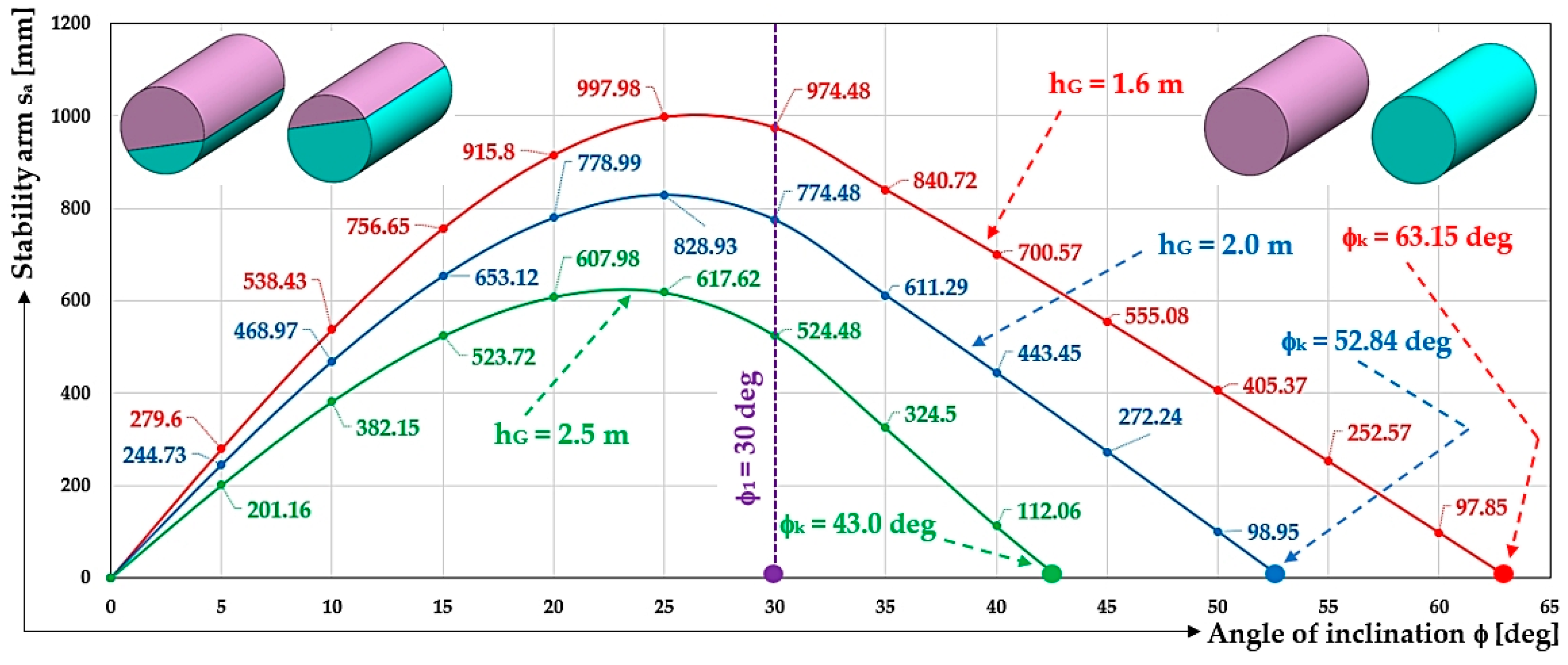
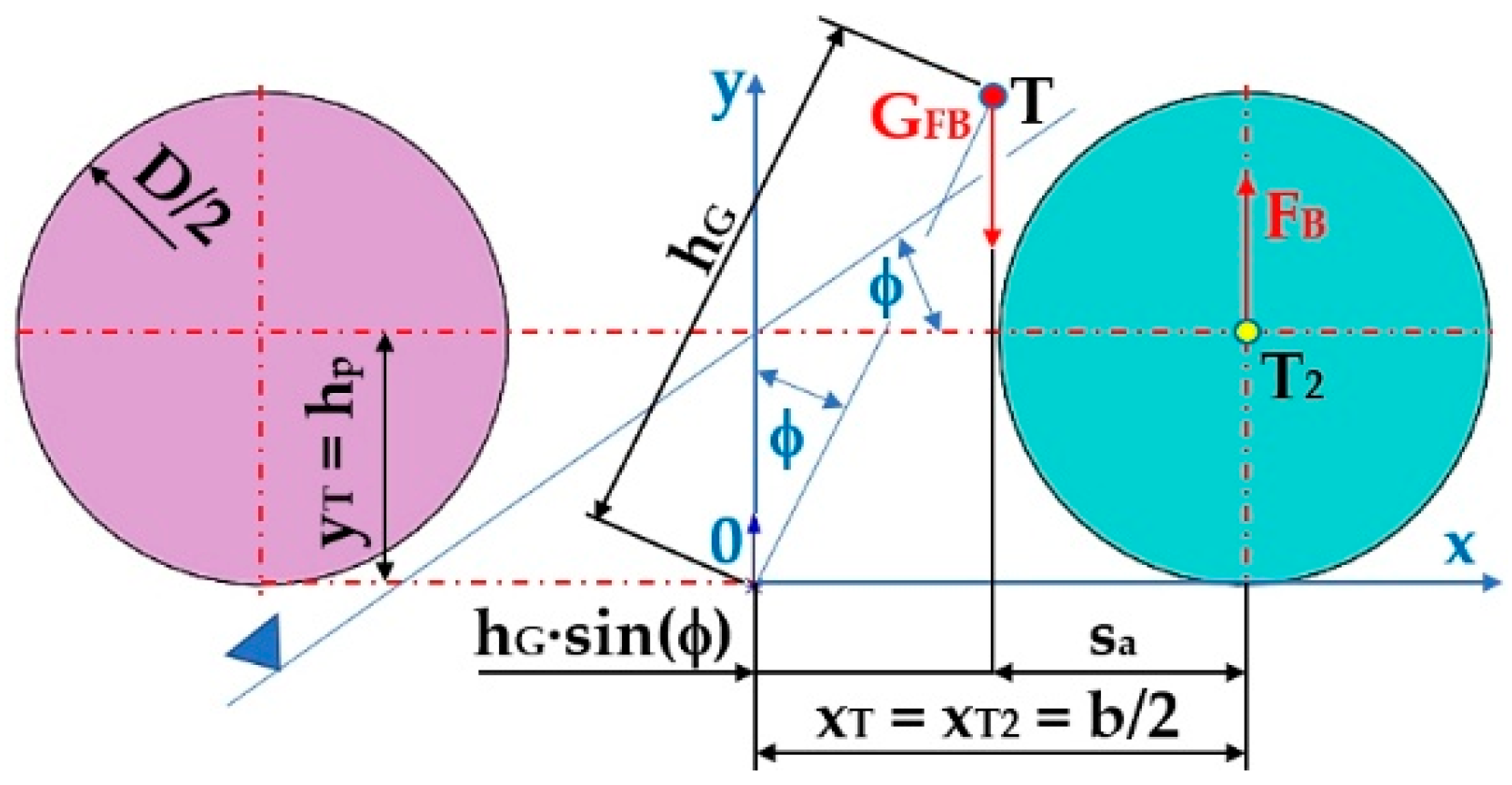
ϕ d e g 0102030405060
F B 60 ϕ N  115.7715.2413.4511.449.839.569.53
S 60 ϕ 10 6 · m 2 8040.467770.246857.595832.785011.914874.244858.95
1 See Table 18.
Disclaimer/Publisher’s Note: The statements, opinions and data contained in all publications are solely those of the individual author(s) and contributor(s) and not of MDPI and/or the editor(s). MDPI and/or the editor(s) disclaim responsibility for any injury to people or property resulting from any ideas, methods, instructions or products referred to in the content.