Article

Determination and Progress in Establishing the Robotic Observatory of Space Objects (ROSO)

by
Francisco Espartero
1,2,*,
Javier Cubas
1 and
Santiago Pindado
1
1
Escuela Técnica Superior de Ingeniería Aeronáutica y del Espacio (ETSIAE), Instituto Universitario de Microgravedad “Ignacio Da Riva” (IDR/UPM), Universidad Politécnica de Madrid (UPM), Pl. Cardenal Cisneros 3, Moncloa–Aravaca, 28040 Madrid, Spain
2
ECS Engineering & Astrophysics, Santa Mónica 8 Bajo, Alcalá de Henares, 28804 Madrid, Spain
*
Author to whom correspondence should be addressed.
Machines 2026, 14(5), 532; https://doi.org/10.3390/machines14050532
Submission received: 29 January 2026 / Revised: 23 April 2026 / Accepted: 4 May 2026 / Published: 9 May 2026
(This article belongs to the Section Robotics, Mechatronics and Intelligent Machines)

Abstract

The gradual increase in man-made objects in the space surrounding our planet is becoming increasingly evident. This significant rise in terrestrial materials is reflected in a greater presence of artificial satellites, space debris and waste from space missions. These objects orbiting close to Earth pose a significant risk in the event of uncontrolled re-entry, as well as collisions between the artificial satellites themselves, launch vehicles and space stations in Earth orbit. This article presents the experimental progress achieved during the prototype phase of a new model of robotic satellite observatory (SRO), featuring significant advances in its design and capabilities. These new SROs are intended to have dual capability to operate simultaneously in both scientific and military contexts. The possibility of forming a network with these devices will provide a system that substantially improves orbital determination and the identification of space objects of interest. The result presented here is an advanced model of the SRO, featuring substantial design improvements from both an ergonomic and economic perspective, as well as a significant enhancement in its ability to monitor and track space objects of uncertain origin that may be of interest or considered a threat to security, thereby expanding its Space Situational Awareness (SSA).

1. Introduction

Currently, the surveillance and monitoring of extraterrestrial objects in our immediate environment has evolved significantly in recent decades [1,2]. Since the last century, there have been major advances, with a shift from analog to digital technology [3,4,5]. The study of near-Earth objects, such as asteroids, meteors, comets and even impact debris from the Moon and Mars [6,7], has evolved thanks to advances in the optical means used [8], such as telescopes, astrographs and even small-format wide-field cameras, such as all- sky format cameras. Astrophysical research on these objects suggests that between 40,000 and 80,000 tons of interplanetary matter may reach Earth annually [9,10]. A significant part of this material consists of meteoroids, solid objects of various kinds, moving through space with a size of less than 10 m and greater than 100 μm [11]. These meteoroids may originate, for the most part, from the fragmentation and degradation of various celestial bodies, mainly comets and asteroids [12,13]. Most meteoroids, once detached from their parent bodies, continue their movement in the solar system in orbits very similar to those of the objects from which they originate, but others, however, penetrate the Earth’s atmosphere, posing a potential risk to our safety.
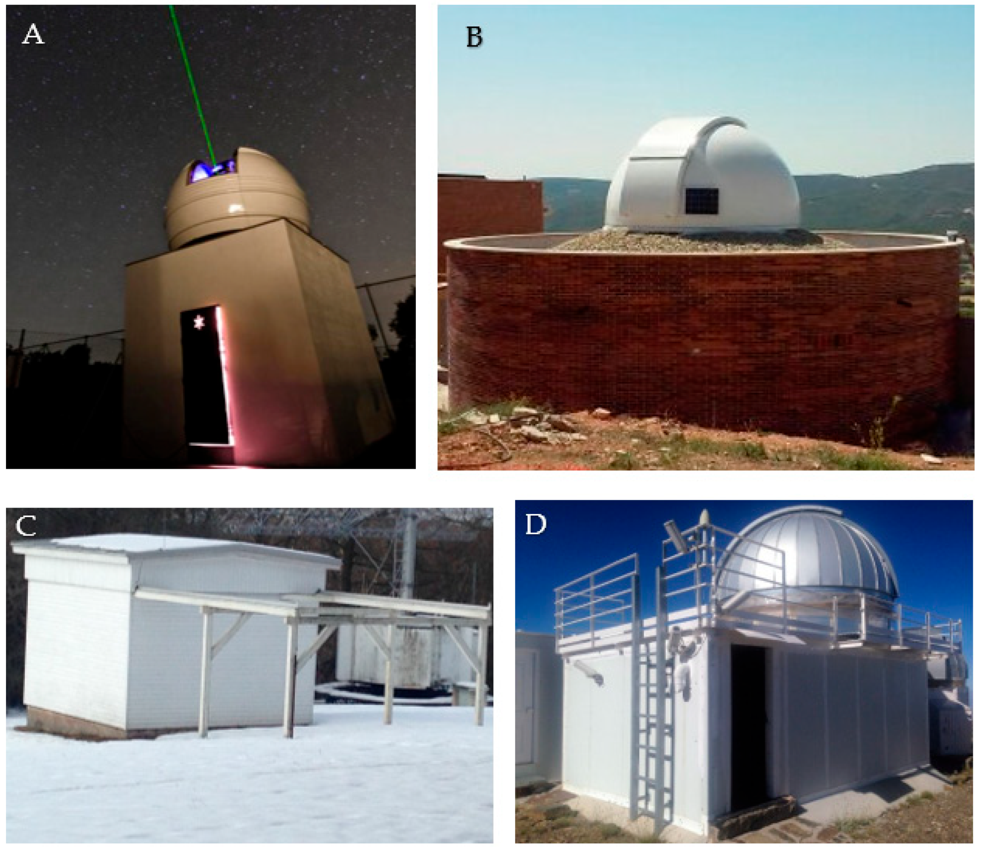
Scientific research into the smaller bodies of the solar system has played a very important role in driving the development of astronomical equipment, to which must also be added the evolution of astronomical observatories themselves (Figure 1), as they have become specific facilities that provide support and security for the telescopes and sensors they house.
These advances, promoted by scientific research in astrophysics, have also contributed to the development and application of photographic sensors, moving from analog devices to CCD (Charge Coupled Device) cameras and later to CMOS (Complementary Metal-Oxide-Semiconductor) cameras. In conjunction with these advances and based on classical observatories (Figure 1), improvements and advances have also been made in the models and designs of observatories [14], which have traditionally been used almost exclusively for astrophysical research [15]. By incorporating new techniques and hardware and software improvements, new advanced models have been developed that can operate without human presence, known as robotic astronomical observatories (RAO).
An exhaustive study of RAOs has been carried out, focusing on those observatories known as “small” because their telescopes are mostly commercial in format and in no case exceed one meter in diameter (dimension of their main mirror). This study and analysis have culminated in the development of new models that can meet current needs. Seeking an exclusive application in the field of near-Earth satellite objects, where the surveillance and tracking of these celestial bodies is paramount [16], the set of robotic devices comprising the observatory, telescope and sensors was named the Satellite Robotic Observatory (SRO).
These devices have yielded good results for their intended purpose, enabling the determination of orbital trajectories and the identification of numerous satellite objects [17,18], using techniques based on astrometry or the determination of light curves [19]. These SROs are equipped with advanced telescopes, many of which have evolved from the classic Schmidt–Cassegrain (S/C) optics to Ritchey–Chrétien (R/C) devices, with the aim of reducing the focal length and providing a large field of view that allows for surveillance with a wider and less restricted field [20,21]. The incorporation of CMOS technology in the new sensors has also made it possible to obtain more accurate images and data, with greater sensitivity and shorter exposure times [22,23], as well as reducing noise and increasing the quality of the images obtained in FITS format (Flexible Image Transport System). These improvements also include a new type of commercial software [24] that allows FITS image data to be transferred in TLE (Two Line Element) format, enabling this information to be integrated into specific software that can determine and identify the orbital trajectories of these objects.
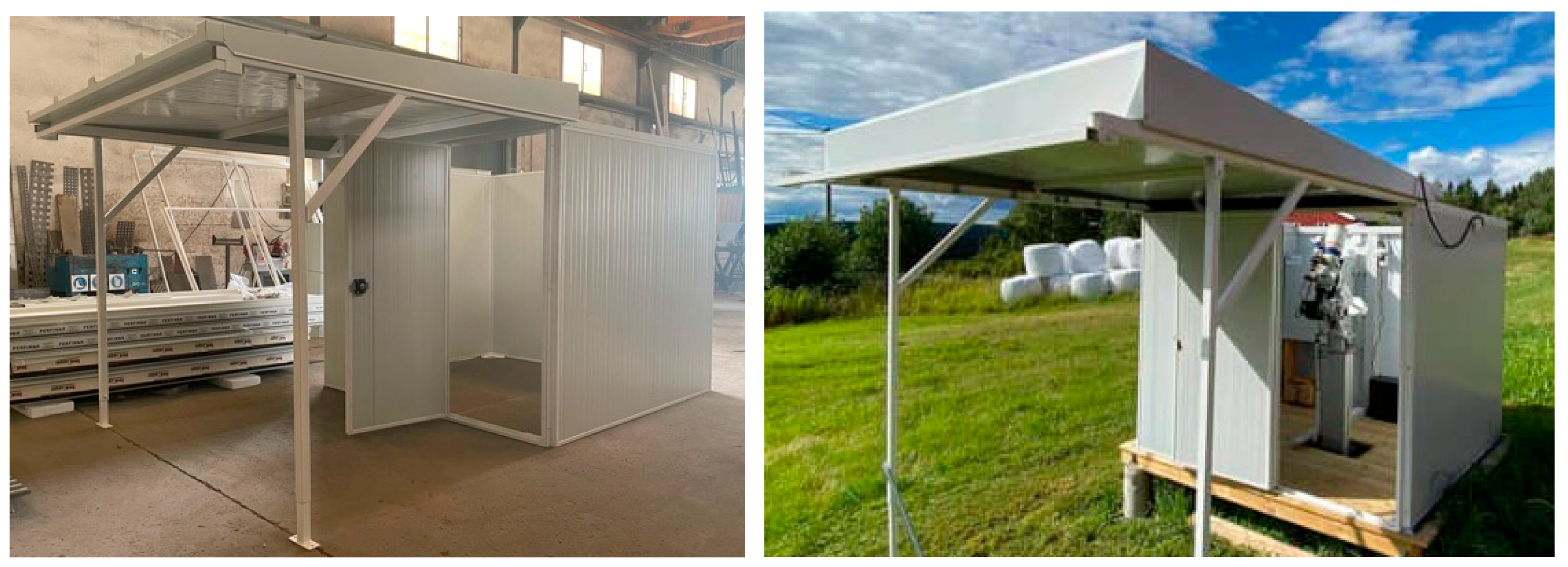
The traditional domes and roofs of observatories have evolved, as has the equipment they house, adapting to new requirements [25,26]. New SROs incorporate advanced roll-off roofs (Figure 2) or double-opening systems that meet the needs of observatories housing two or more telescopes [27,28].
Understanding the main technical characteristics of the different RAO models is essential for determining the best techniques needed to design a new robotic observatory model for tracking and monitoring satellite objects. This has been the fundamental idea behind our work from 2011 to the present day; different types of RAOs have been visited and studied at different sites, with very different purposes and configurations, as shown in Table 1. The previous list of observatories also analyzed their main characteristics, such as the roof, the materials used in their construction, their degree of automation and their capacity to service the telescope inside. Although their locations and purposes vary, it has been noted that there is no manufacturing standard. Each observatory is designed exclusively for each telescope and each project, which makes this task complex and expensive, as well as making it difficult to compare their characteristics.
This table compares astronomical observatories with small telescopes (diameter less than 1 m) based on their ability to detect a celestial object (*) in brightness magnitudes (their value may be one or two units higher if the sky is of excellent quality). The telescope used as a reference is also shown according to its diameter in inches and its optical configuration (**): S/C, Schmidt–Cassegrain; R/C, Ritchey–Chrétien; Dobsonian and Refractor. https://srmastro.uvacreate.virginia.edu/astr313/lectures/telescopes/telescopes_lgp.html (accessed on 17 December 2025). This analysis and study of RAOs indicates that these observatories were designed for a very specific purpose (Table 1), with designs and models that are not susceptible to updates. There is a clear need to design a new model of robotic observatory for tracking and monitoring satellite objects and space debris: simultaneous surveillance and tracking of space objects using small telescopes and advanced sensors such as CMOS requires a new design concept that allows them to be integrated in a simple, safe and effective way to capture simultaneous data and images, offering a new dual capability for the new needs of identifying and determining the trajectories of the increasingly numerous satellite objects.

2. Materials and Methods

The growing demand for space surveillance services presents a new challenge [29]. Robotic observatories must evolve to meet the new requirements of both public institutions and government bodies, as well as private companies within the rapidly evolving space sector, where the number of satellites is gradually increasing due to new missions, satellites and space activities [30].
The need to gather information on man-made objects orbiting our planet presents new challenges, such as the requirement for a mobile observatory model that can be relocated according to the needs arising from the detection of artificial satellites, constellations, space debris and space missions, and which can also offer various possibilities and configurations to meet the interests of the defense and security industry. Dual capability, agility, portability and the rapid integration of tracking systems and sensors are shaping a new SRO model based on new requirements for a greater number of sensors at different locations. To meet these new objectives, a model needs to be developed which, building on previous SROs, offers a series of substantial and innovative improvements, providing functional solutions with a design that is agile, robust, effective and more economical than current models. The method applied in this work has two distinct yet complementary parts.

2.1. Technical and Environmental Considerations

Firstly, based on a study of SROs and traditional astronomical observatories [31], technical improvements previously applied in large-scale observatories (primarily dedicated to astrophysical research) have been incorporated, but in our case, have been adapted to the new model we aim to develop [32]. In this way, technical measures are adopted whose functionality has been proven and tested, but applied on a smaller scale and adapted to a new format of mobility, as detailed in Table 2 for RAOs and SROs [33,34].

2.1.1. Weather Station

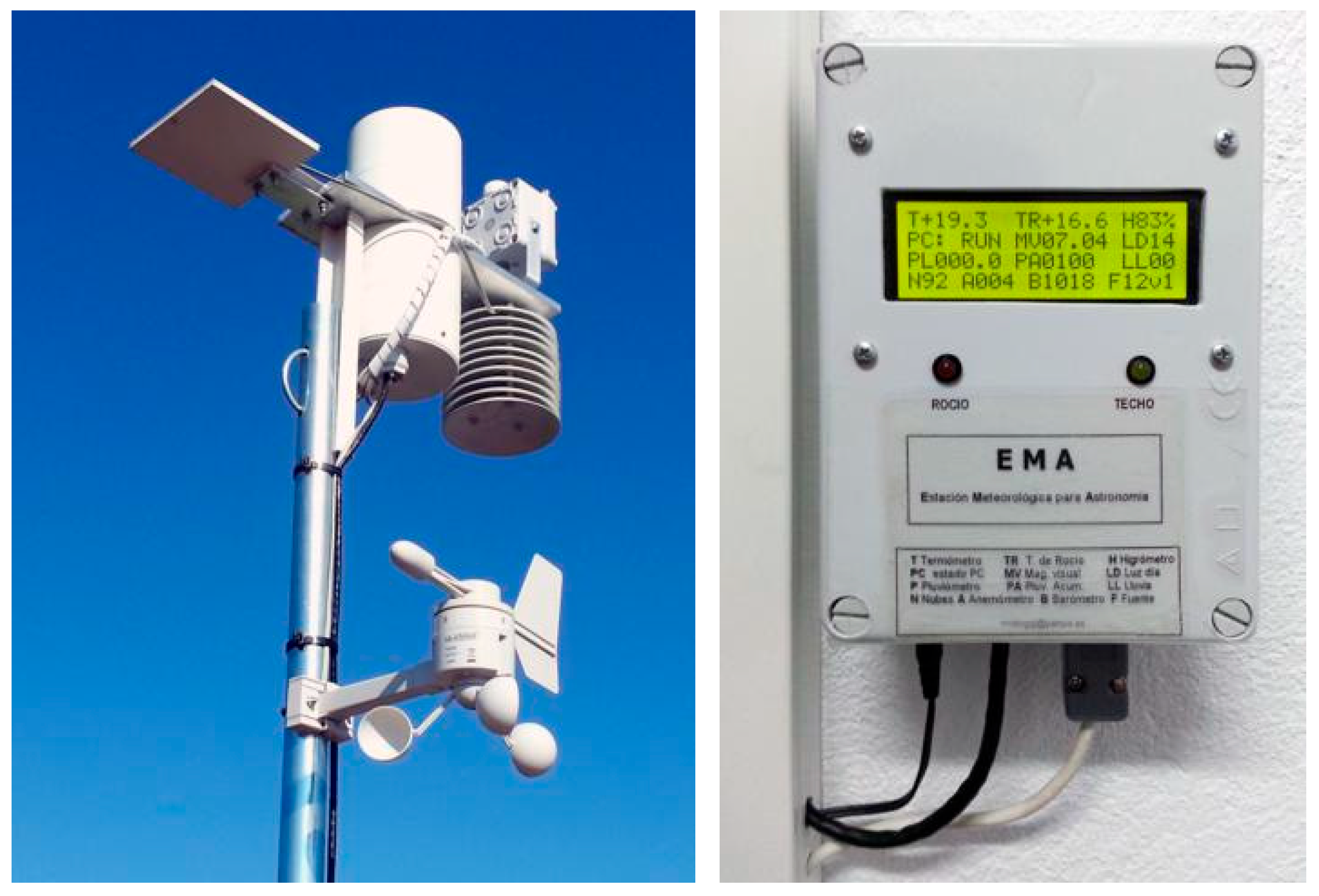
A weather station designed for scientific astronomy applications (Figure 3) can measure sky brightness (Sky Quality Meter), air speed (anemometer) or cloud cover (using a Peltier system that measures the difference in infrared radiation between the ground and the sky). The latter is the most relevant indicator for our protection system, as when cloud cover reaches 33%, the observatory roof is closed as a safety measure [35,36,37]. At this point, the station sends a signal to the automatic protection module to close its sliding roof, while the telescopes and sensors remain on standby. The system does not shut down and remains in “standby” mode until the cloud cover reduces, and it automatically resumes operation.
The weather station ensures the correct functioning of the system (observatory roof, mounts, telescopes and sensors) and its operating logic is quite intuitive. The entire system is interconnected, so that it activates at sunset and deactivates at sunrise, allowing it to be switched off and the observatory roof to remain closed during daylight hours. By switching on/off according to the brightness of the sky, there is no need to update any astronomical clock or timer as the days go by, as it is self-regulating on a daily basis [38].
All operations begin with the opening of the dome shortly after sunset, provided that the sky brightness value exceeds 12 mag/arcsec2 (visual magnitude limit −3), as images obtained at lower values become saturated. When this value drops shortly before dawn, the systems stop operating, and the observatory dome is closed.

2.1.2. Optical Supports and Lightweight Pillars

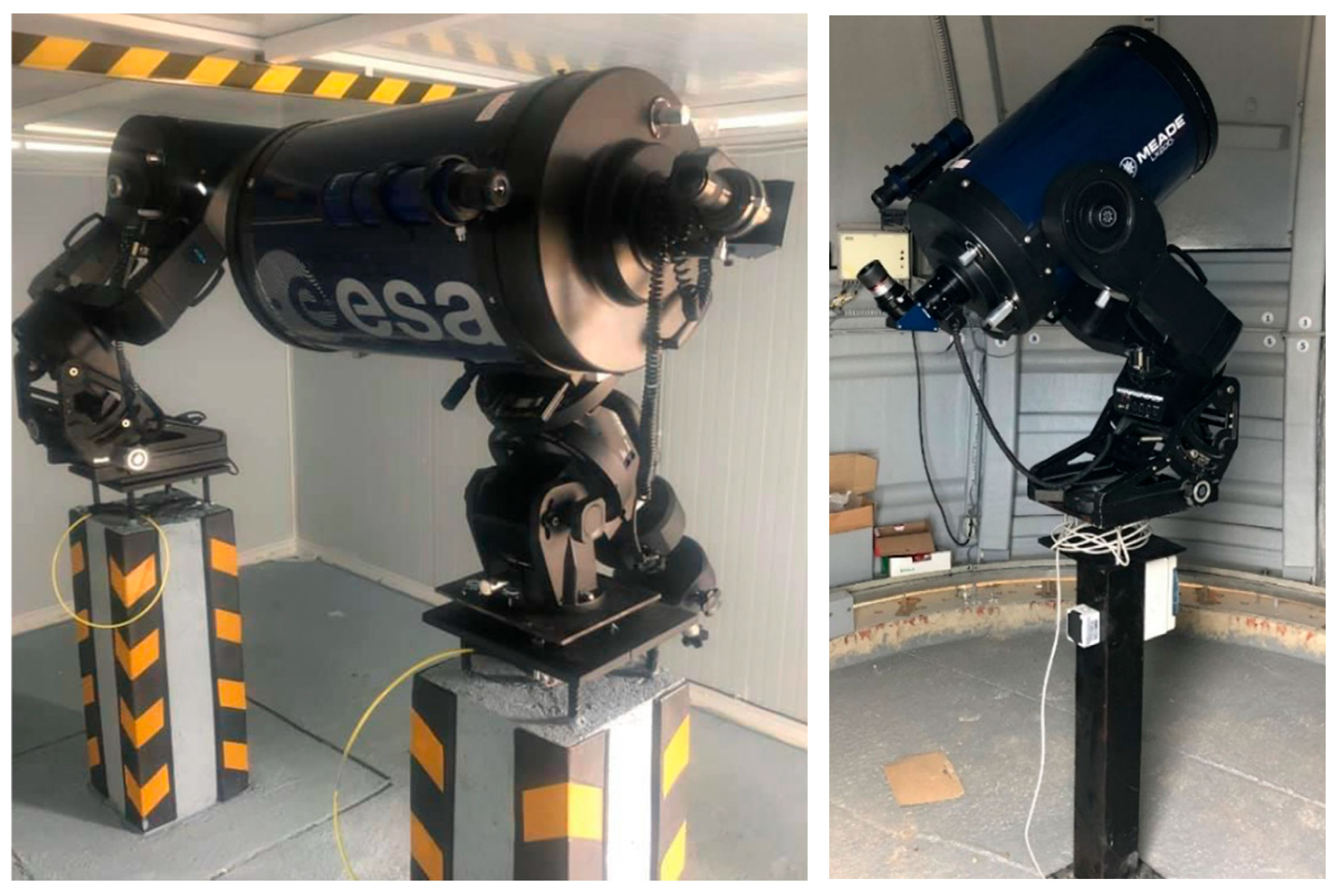
For the observatory to have a dual and versatile configuration, it needs a new design for the base that supports the telescopes and their mounts [39]. A concrete pillar cannot be used, as the new supports must be lightweight and strong, but at the same time easy to dismantle if the observatory needs to be moved. The pillar itself must have a hollow interior (Figure 4) to house the electrical/electronic and data connections, facilitating a quick and secure connection to the telescope and its sensors [32].

2.1.3. Lightweight, Agile and Resistant Cover and Mechanics

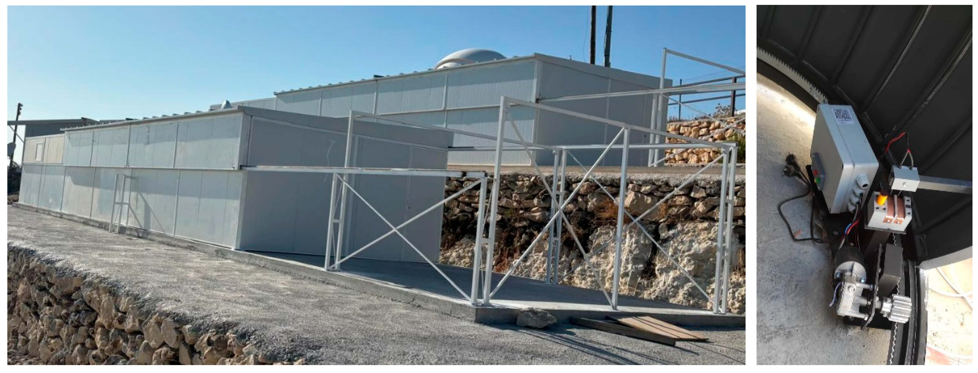
The observatory’s mechanical opening/closing systems must be made of mechanically resistant materials that are durable against inclement weather and corrosion [40]. To this end, appropriate materials must be used that are lightweight and do not add excessive weight. Well-adjusted and balanced rack-and-pinion mechanical systems are a good solution if they are correctly adjusted using a variable speed drive that provides smooth, progressive movement (Figure 5). This mechanism, combined with a lightweight roof, can give optimal results if its movement is supported by self-lubricating carbon steel bearings [41].
The walls and roof are made of sandwich panels, and the structure is made of hollow carbon steel tubing. This gives it the necessary rigidity and strength while also allowing this material to be easily assembled/disassembled and even transported, due to its light weight. The zippers and internal mechanical systems are made of galvanized steel, which prevents damage to the motor pinion during friction movement.

2.1.4. Insulation, Temperatures and Stray Light

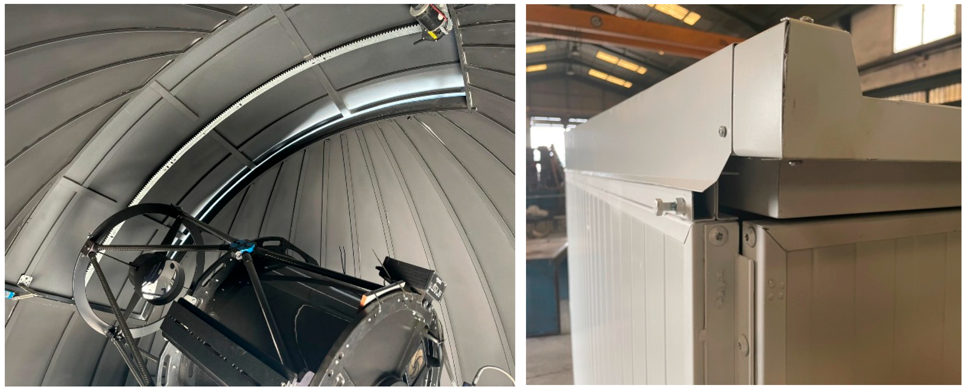
The RSOs have provided valuable information regarding the observatory’s operating dynamics and some areas for improvement that are now being considered in this work (Table 1 and Table 3). An improved design allows the observatory to increase its thermal insulation, minimize the effect of stray light (Figure 6, left) and reduce humidity. When assembling the roof and walls, sufficient space can be left to avoid a high thermal contrast between the interior and exterior of the observatory, as this significantly impairs the optical performance of the equipment and the quality of the data provided by the sensors [42]. This is achieved with an overlapping design between the roof protections and the roof’s running/movement rail (Figure 6, right). This system also prevents water or snow from entering due to the effect of the wind. With regard to the interior finish, it is advisable to apply a fire-retardant coating that is also matt black (non-glossy) to avoid unwanted reflections and stray light, which are very detrimental to such sensitive instrumentation.

2.1.5. Automation

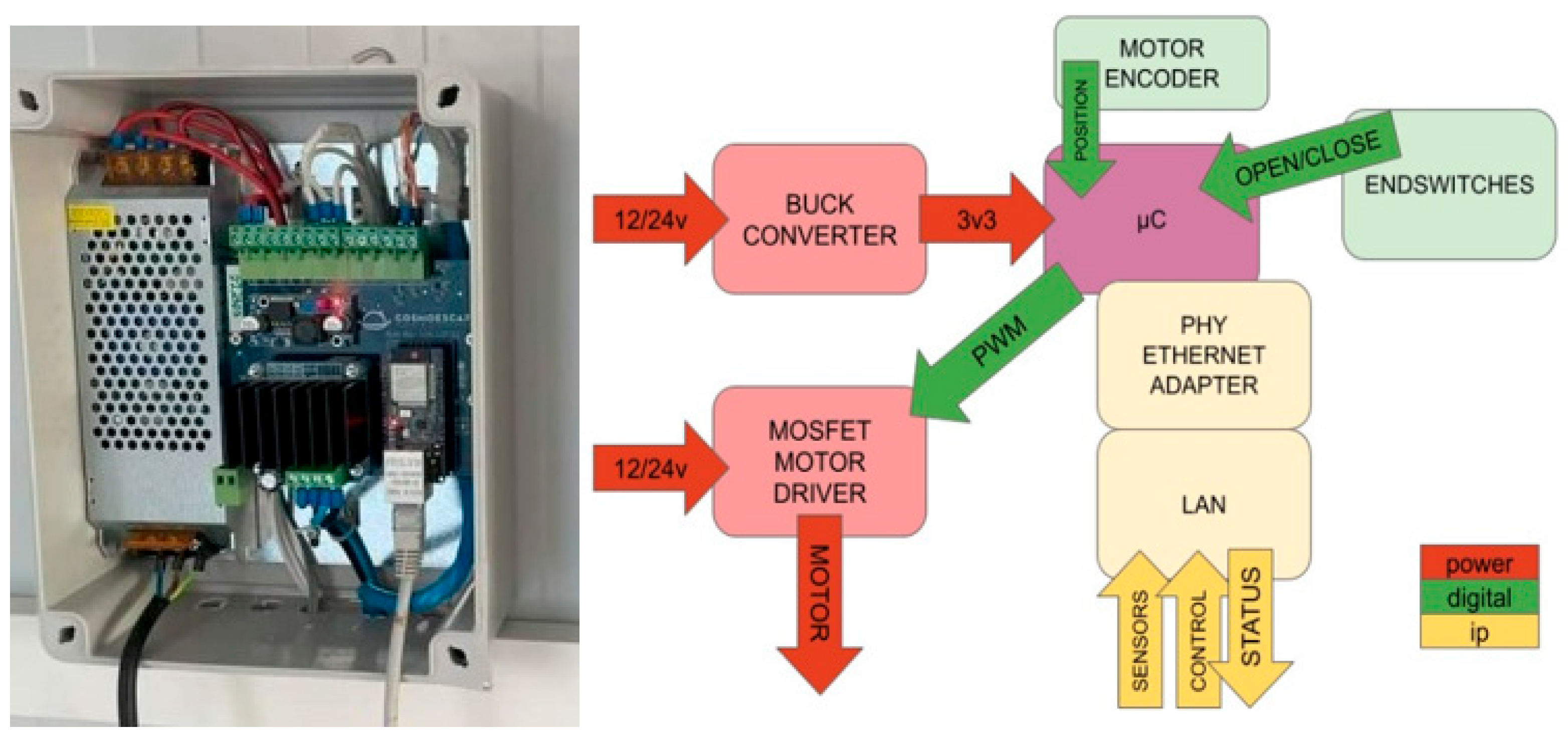
This roll-off system integrates complete control of the observatory’s mobile roof into a single device, without the need for a specific PC for control, although this equipment is usually installed to integrate all optical devices and sensors that operate autonomously or under remote control [43]. The microcontroller directly manages the motor via PWM (pulse width modulation), reading the position in real time through the encoder and ensuring precise and safe movements. Limit switches provide an additional layer of physical protection against mechanical or control errors. The power supply is suitable for 12/24 V installations (Figure 7).
The system connects directly to the network via Ethernet, enabling remote control and monitoring without the need for intermediate software (Figure 7). It uses ASCOM-ALPACA controllers to operate. One of its main new features is native integration with multiple external sensors (including meteorological sensors), whose statuses directly influence opening or closing decisions. The result is a compact, robust and autonomous solution, designed for remote observatories without the need for continuous maintenance.

2.2. Operational and Functional Considerations

Secondly, based on the analysis and study of the observatories shown in Table 1, and in order to identify the key elements and most relevant factors—so that action can be taken to improve the design and capabilities of an SRO—we have drawn on the advice of an expert team of architects and engineers who, objectively, have identified the most critical elements of an observatory whilst establishing a system that allows for a quantifiable and realistic assessment of the technical elements comprising these facilities.
A team of experts has identified the key critical elements (Table 2) and technical aspects (Table 3) that can determine the optimal performance of RAOs and SROs through a quantifiable assessment.

2.2.1. Based on Their Use

The following have been identified as critical elements to incorporate or improve:
Ease of Access
Traditional observatories are designed such that the facility is typically accessed from ground level, with visitors then ascending to a dome or upper level via stairs or mechanical means (they usually comprise several rooms on different floors). This is often a hindrance to maintenance work, and staff are restricted in their movements and duties. The new RSO opts for a simple, ergonomic and functional design, in which all equipment and facilities are located on the same floor and within the same space, thereby simplifying and streamlining all operational and maintenance tasks.
Horizon Visibility
The horizon has traditionally been disregarded on the grounds that the images obtained are affected by atmospheric refraction and are therefore invalid. In RSO observations, however, the horizon is considered important for obtaining astrometric data and is not disregarded; rather, the aim is to cover the entire sky to the greatest extent possible.
Telescope Capacity
An RAO incorporates a single telescope, whereas RSOs may have two or more telescopes, depending on the different optical models and mount types.
Thermal Insulation
This has traditionally not been a major consideration, as observatories used to open their domes one or two hours before starting work in order to equalize the internal and external temperatures, since temperature differences can damage optical systems. In the new RSO models, this option has been implemented, allowing observatories to open their domes almost as soon as they begin operating. This enhances safety and reduces the risk of environmental pollution.
Ease of Transport
Normally, observatories cannot be moved, as they are either fixed to the ground or their unique dome-shaped design makes it very difficult to move them or change their position. The new RSO observatories, however, do offer this possibility and can be moved quickly and easily using a crane lorry or similar vehicle.
Wind Conditions
Wind can cause telescopes to move and vibrate, which can render the captured images and data unusable. A well-designed cover helps to minimize this effect, so classic RAO telescopes should have their covers closed when wind speeds exceed 40 km/h.

2.2.2. Regarding the Roof

As the main structural element of any observatory, the following configurations have been considered [44].
Single Roof
A basic structure used mainly for small or amateur-level observatories. It is usually a simple and very economical design.
Double Roof
A structure capable of housing more than one telescope, with two independent roofs that allow for the use of either half of the observatory or the entire structure.
Double Housing
Large-scale roofs are installed in observatories that collectively house a large number of telescopes.
Dome
A model that, due to its height, allows for the installation of large telescopes.
Retractable Roof
An innovative design allows the telescope to be positioned so that opening the roof provides a clear view of the entire horizon. An ergonomic, simple model offering good value for money.
Lower Access Dome
A classic observatory model that can be large in size, but only accommodates a single telescope inside.
Side Access Dome
An ergonomic dome design comprising a single structural element, allowing access via a small door. This is a small model intended for astro-tourism and small telescopes.
Shell Dome
A dome design consisting of several interlocking sections that slide past one another, allowing it to open almost completely. This is the most expensive model.
Table 3 presents a weighted matrix in which critical elements are compared according to their use (from Section Ease of Access to Section Wind Conditions) against roof types (from Section Single Roof to Section Shell Dome), using an objective rating criterion (from 1 to 10) that indicates their quality level.
The commercial models listed in Table 3 have been sourced from the following companies: Scope Dome https://www.scopedome.com/?page_id=2924&lang=en, (accessed on 27 December 2025).Omegon https://www.omegon.eu/observatories/17Dome, (accessed on 27 December 2025). Parts https://www.astrogfk.com/projects/ (accessedon 27 December 2025). and ECS https://esparterocs.com/en/home/ (accessed on 14 December 2025). Having analyzed the market prices of this equipment, it is clear that the cost of these robotic observatories varies, with the model described in Section Single Roof being the cheapest and the one in Section Shell Dome the most expensive.

3. Results

The results presented in this paper were obtained during an initial prototyping phase, and some of them were collected independently, as they have not yet been fully integrated into ROSO.

3.1. Potential for Improvement and Development

Next, the main technical (critical) aspects affecting the use of an observatory based on its roof covering were considered in order to reflect its final value (Table 3). Considering six critical elements, a theoretical maximum value of 60 is established, which contrasts with the values obtained between a minimum of 35 (58% of the maximum) and a maximum of 42 (70% of the maximum), suggesting that there is significant room for improvement to reach 100%. RSOs have evolved from RAOs with new improvements and advances, but in this work, areas have been identified where further progress and improvement can be made to achieve a new observatory model.
Based on these considerations, the maximum score achieved in the assessment by the external team of architects and engineers would be 70% at most, and our ROSO aims, as a realistic target, to increase this capacity by 20%, reaching 90% of the total with a score of 54. New models have been designed, and the key improvements required to develop a robust, mobile and effective ROSO, capable of accommodating more telescopes and sensors, are now known.

3.2. Integration and Autonomy

The set of all the devices, equipment and facilities resulting from the above has been named the Robotic Observatory of Space Objects (ROSO) and, although its main objective is to monitor artificial objects close to our planet, it is worth highlighting its dual capacity, as its use and capacity also cover natural objects such as meteoroids, NEOs and NEAs.

The optical equipment and sensors are commercially available and have been selected for their efficiency, sensitivity, ease of use, control and integration [45]. It is essential to integrate all ROSO equipment together, which has been achieved under the ASCOM protocol https://ascom-standards.org/ (accessed on 3 January 2026) ensuring the proper functioning of all devices and the acquisition of accurate, high-quality data, which is the ultimate and fundamental objective of this project [46,47].

3.3. Previous Data

The images shown below were captured using a telescope and separate sensors, and will be integrated into ROSO following its manufacture and final validation. They show how the same technique can be used to obtain images of both artificial and natural objects.
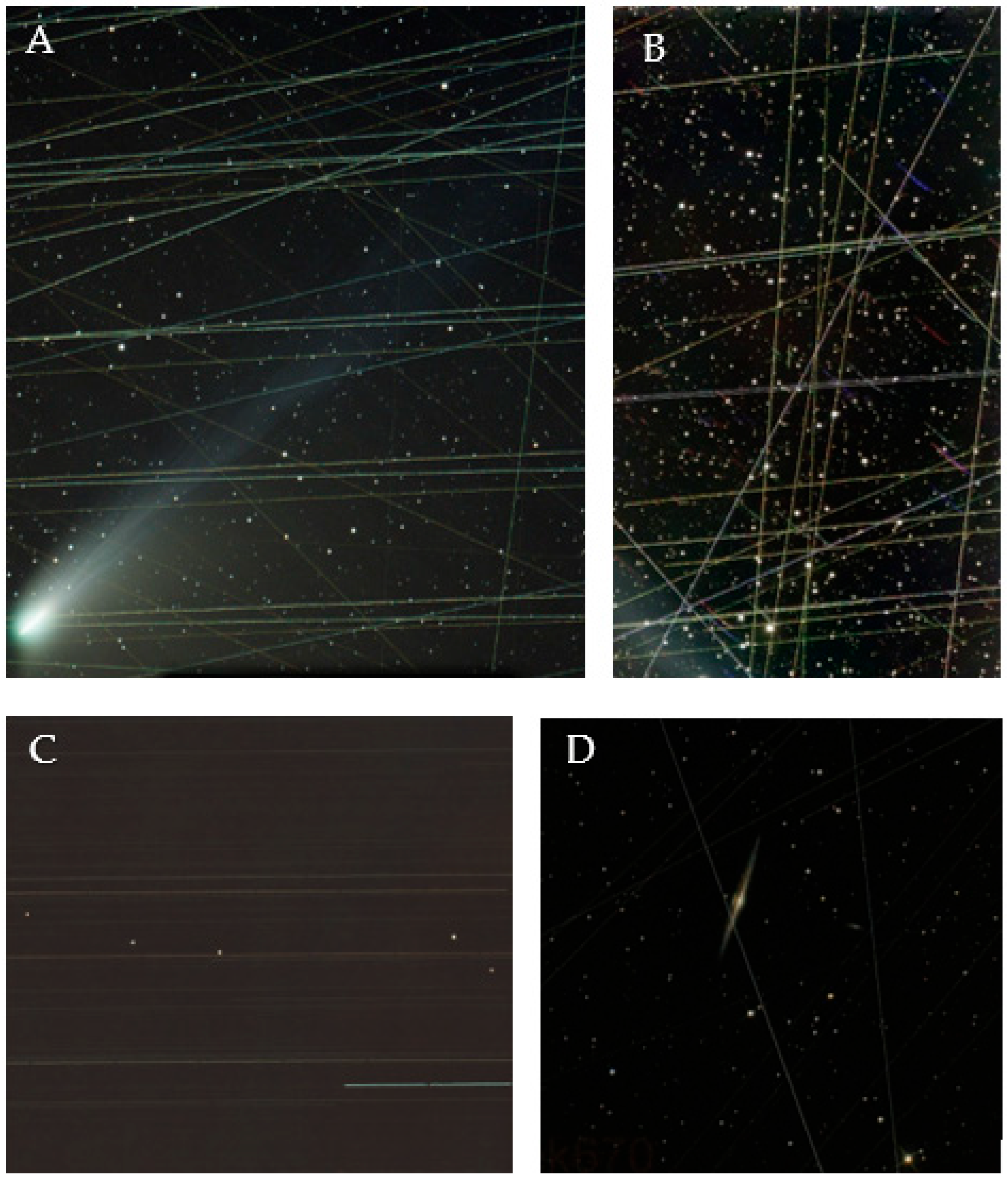
Numerous tests have been carried out with commercial telescopes of different optical configurations, ranging from S/C to R/C (see Section 1) to the new Rowe–Ackermann-Schmidt astrograph models, which have been fitted with ZWO and CMOS sensors. The results obtained and the images captured have been very revealing and raise high expectations for the new SOOs. Figure 8 shows several image captures with exposure times of 30 s, stacked and processed with DeepSkyStacker v.5.1.6 and SkyTrack I v.4.4.7, a Meade 10” S/C telescope (Meade, Irvine, CA, USA), and a QHY628C camera (Atik Cameras. 2021. Cambridge, UK). These telescopes and sensors are currently integrated, installed and calibrated at the AstroCamp Observatory in Nervio (Spain) https://www.astrocamp.es/ (accessed on 4 January 2026).

3.4. Technical Advances and Improvements

Section 2.1 describes the new methods, developments and materials incorporated into the RSO.

3.5. Lower Cost and Dual Capability

The new observatory and its new capabilities, as described in this paper, help to reduce production and maintenance costs, whilst offering the dual capability of monitoring and tracking multiple objects simultaneously. This results in a significantly lower overall cost. ROSO is simpler, cheaper and has greater capability.

4. Discussion

Classic robotic observatories have a dome cover, which is usually made of polyester and fiberglass. They are manufactured using standardized molds, which means that their dimensions are small and they cannot house more than one telescope. These materials deform over time and are very expensive to repair, so they are usually replaced with an identical model.
Taking the roof (ceiling or dome) as the main distinguishing feature, a detailed study has been carried out on the capabilities of the observatories in Table 1, considering their main advantages and shortcomings. In order to obtain a realistic estimate, a generic evaluable classification has been established, in which, according to the study presented in Section 1, the factors and facilities have been quantitatively evaluated (Table 2) to determine their degree of quality and proper functioning. This reference and assessment system, in which the maximum quality value of the main critical aspects is estimated, has served as a reference for the technical evaluation of RAOs and SROs.
SROs have provided the basis for the development of a robotic observatory capable of monitoring and tracking satellite objects. The need for multiple pieces of equipment and sensors that can operate simultaneously and perform complementary tasks was the main motivation for the SRO, but the significant increase in satellite objects and the growing demand from industry and private entities to meet this need have resulted in an immediate new requirement [48,49].
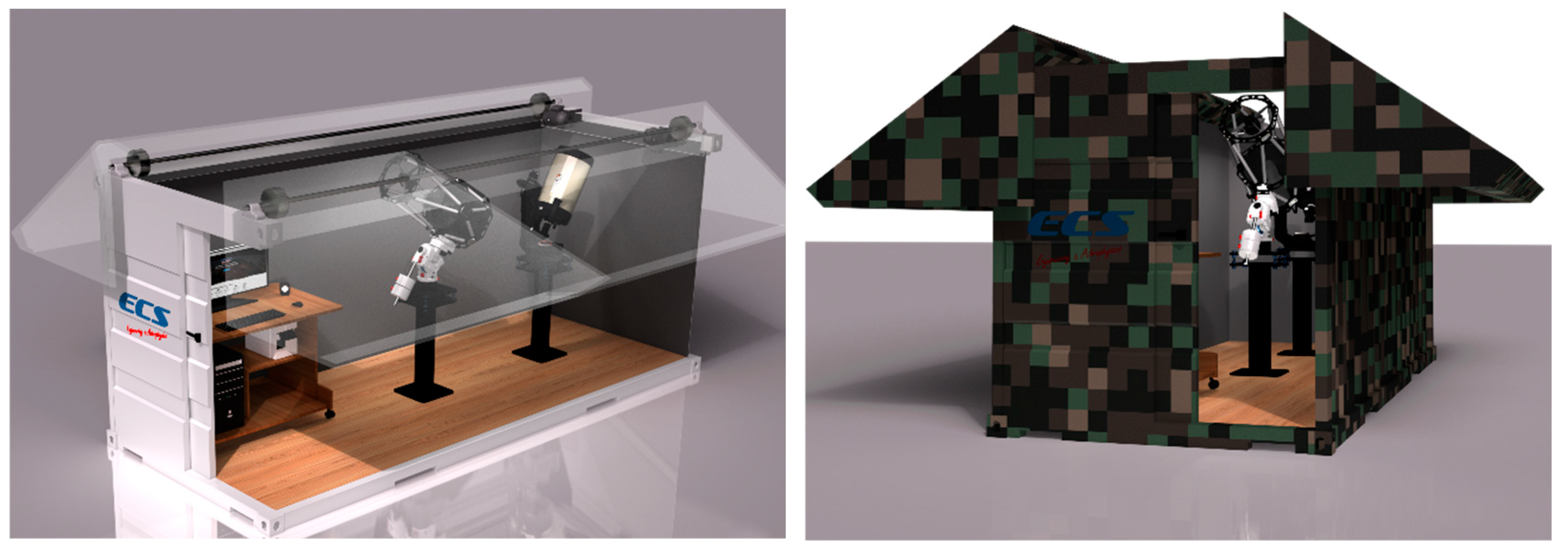
A new RSO model is needed that is transportable and allows observation and tracking campaigns to be carried out at different locations (to determine good locations and perform effective site testing). It is also considered important that the new SRO can be configured into a network [50] to improve astrometric accuracy and the ability to determine an object’s orbital parameters [51]. These new improvements would be decisive in identifying objects of dubious origin and would be of great interest in terms of security and from a military [52,53,54] and defense perspective (Figure 9).
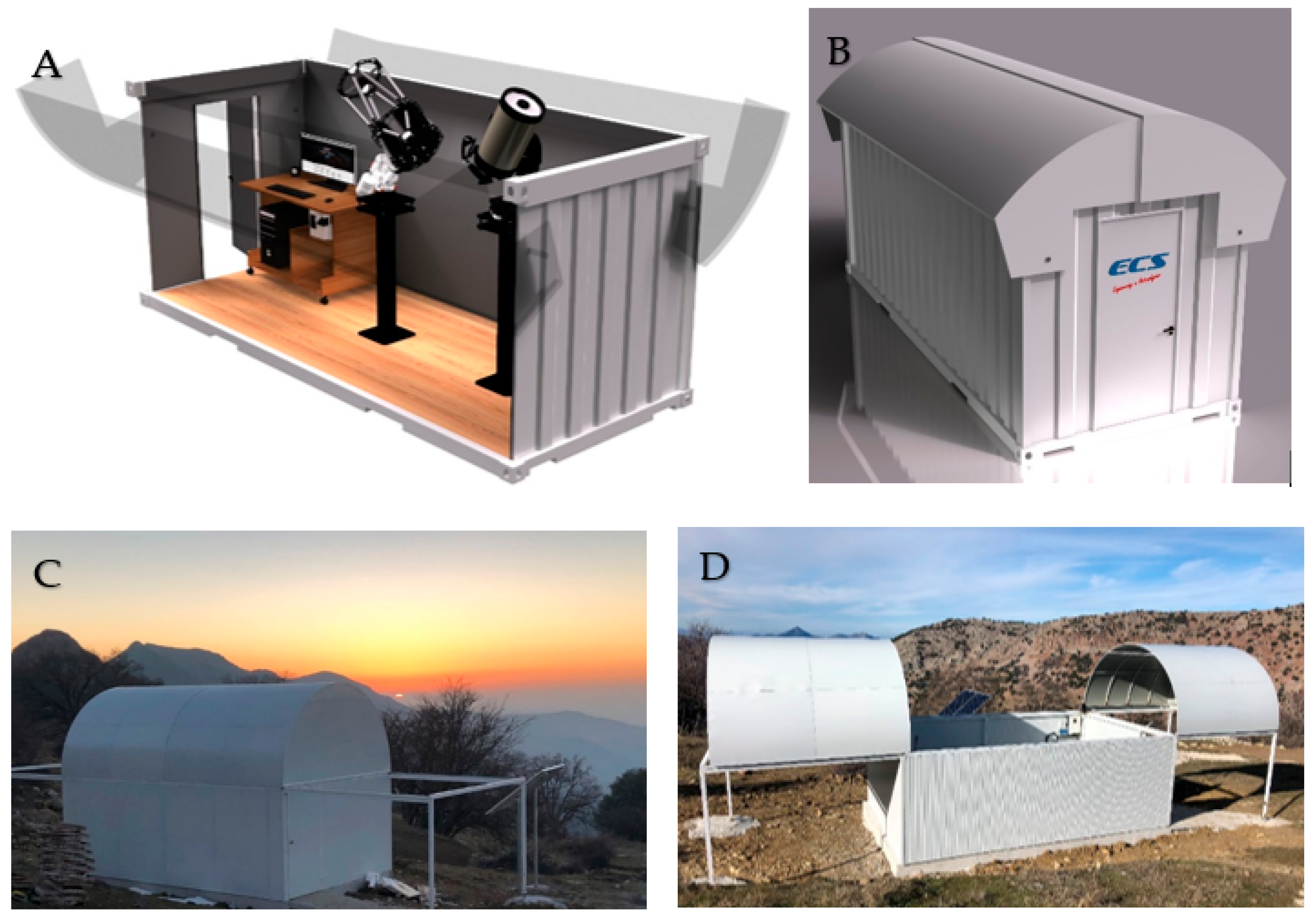
The double-sloped roof allows telescopes to be placed underneath it and, when opened, provides an unobstructed view of the entire horizon. This system was tested in prototypes and subsequently tested at SRO with very positive results, as it is a fast, simple and safe opening/closing system from a mechanical point of view.
As another option that serves as a counterpoint, a new roof model with similar characteristics has been modeled, although the roof does not slide according to its slope, as it is vaulted, but rather rotates on a double lateral axis (Figure 10), with a similar result to the previous one. This system also leaves the horizon free for optical systems and does not leave any blind spots, as can be seen in Figure 10 (images below), with a similar design, but which is not 100% effective and free of obstacles.
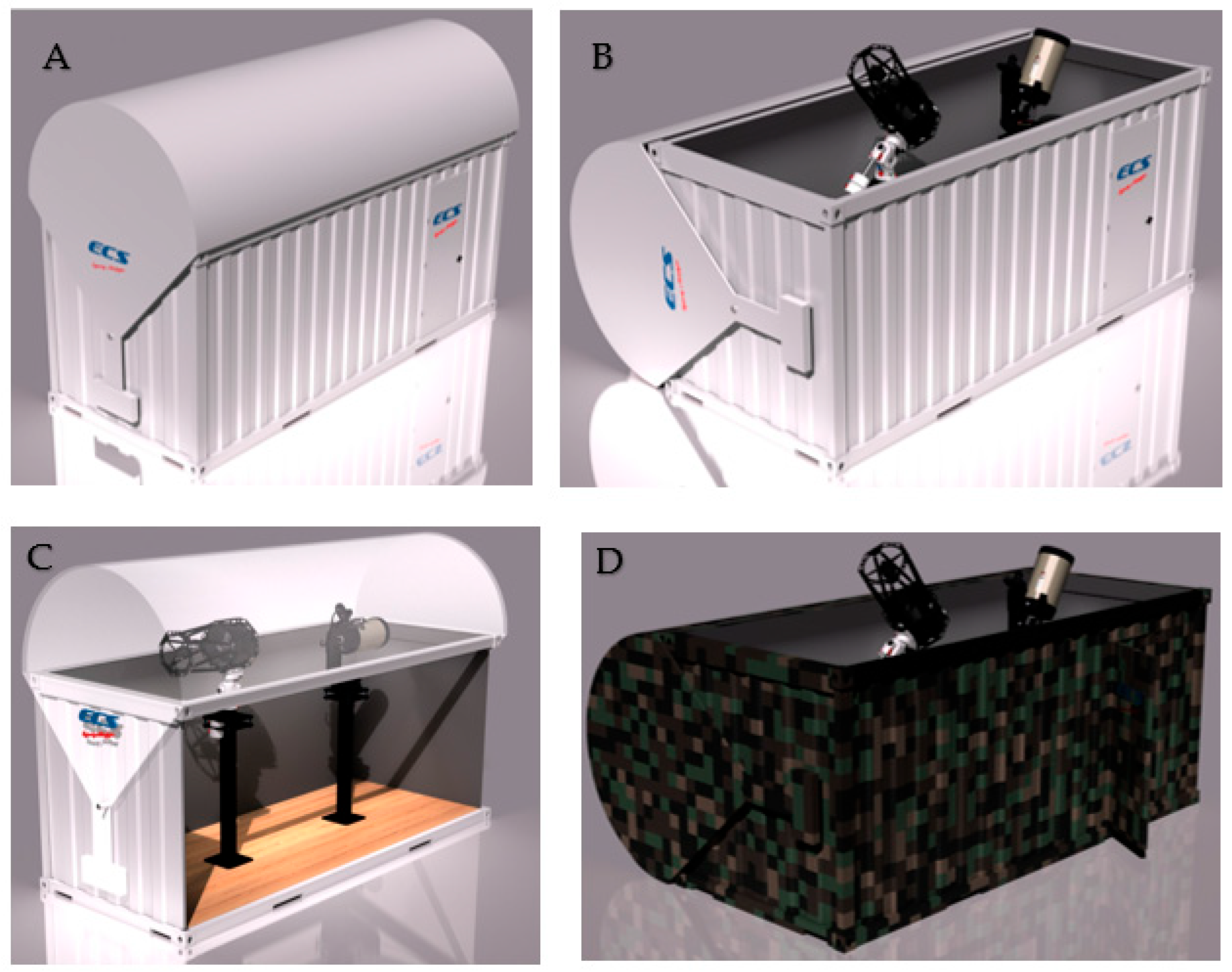
These roof options are very practical because, when combined with the requirements set out in this study, they result in a new observatory model. Taking into account all the premises that have been set out and as a result of the research and experience gained, there is one last element to incorporate that can further improve the capabilities and ease of use. The roof could be further simplified by installing it as a single piece, which would make it more secure when opened and closed (Figure 11). To achieve this, a single vaulted roof could be incorporated to completely cover the base box. The roof has a double axis on the side that can be rotated either manually or electronically, since, as can be seen in the following figure, the cover has a double lateral extension, which incorporates a counterweight. This mechanical movement system makes it much easier for the vault to rotate to open and close with minimal effort. The set of counterweights ensures durability, ease of movement and minimum energy consumption for proper operation.
This model provides additional security that affects the entire observatory, as the roof can operate independently from the rest of the equipment. This configuration provides independence from the observatory’s equipment, which provides double security in the event of an unforeseen event or device failure.
The Robotic Observatory of Space Objects (ROSO) is the end result of this work and aims to help improve terrestrial capabilities for surveillance, tracking and identification of satellite objects in our immediate environment and those objects of unknown origin, both artificial and natural. These fast-moving, agile and functional observatory models are part of a new generation of modular observatories designed to help keep our local area safe.

5. Conclusions

This paper presents a new robotic observatory model designed to monitor and track satellite objects in the vicinity of our planet, called ROSO. The new requirements demanded by the aerospace sector have been taken into account due to the increase in objects in our near-space environment.
Numerous possibilities for improvement have been studied and identified, where action can be taken with new designs, automation systems, meteorological sensors, mechanical and structural improvements, ranging from new roof models to designs that facilitate transport, such as the possibility of manufacturing customized modules according to the new requirements of telescopes and sensors. The ROSO aims to fill a design gap and open up new possibilities in the ground segment to provide dual capability to a new generation of robotic satellite observatories that are safer, more versatile and more economical.
  • They can be manufactured in different sizes, depending on requirements.
  • Made from steel with hollow sections; sturdy, safe and easy to transport.
  • Good thermal insulation, fire-resistant and blocks stray light.
  • Secure, single-piece cover that allows total visibility, safety and mechanical improvements in closing/opening.
  • Easy to standardize and mass-produce.
  • They are modular. They can be installed longitudinally or to form a network of several units.
  • Easy integration of sensors and devices under the ASCOM protocol.
  • The possibility of installing solar panels on the cover.
  • Very easy to transport due to their lightweight structure and quick installation.
  • They have the capacity to house several telescopes and sensors.
  • Much lower cost compared to other observatories with domes.

Author Contributions

Conceptualization, F.E.; methodology, F.E. and S.P.; validation, F.E., J.C. and S.P.; investigation, F.E.; resources, F.E.; data curation, F.E.; writing—original draft preparation, F.E.; writing—review and editing, F.E., J.C. and S.P.; visualization, F.E. and S.P.; supervision, J.C. and S.P. All authors have read and agreed to the published version of the manuscript.

Funding

This research received no external funding.

Data Availability Statement

The data supporting this study’s findings are available from the authors upon reasonable request.

Acknowledgments

The contribution of images, sensors and the different RAO, SRO and ROSO models provided by ECS Engineering & Astrophysics, Castro Tirado and Ramirez Bolivar.

Conflicts of Interest

Author Francisco Espartero was employed by the company ECS Engineering & Astrophysics. The remaining authors declare that the research was conducted in the absence of any commercial or financial relationships that could be construed as a potential conflict of interest.

References

  1. Millman, P.M. A general survey of meteor spectra. Smithson. Contrib. Astrophys. 1963, 7, 119–127. [Google Scholar]
  2. Borovička, J.; Boček, J. Television spectra of meteors. Earth Moon Planets 1995, 71, 237–244. [Google Scholar] [CrossRef]
  3. Hemenway, C.L.; Swider, A.; Bowman, C. Meteor Spectroscopy Using an Image Orthicon. Can. J. Phys. 1971, 49, 1361–1364. [Google Scholar] [CrossRef]
  4. Millman, P.M.; Clifton, K.S. SEC Vidicon Spectra of Geminid Meteors, 1972. Can. J. Phys. 1975, 53, 1939–1947. [Google Scholar] [CrossRef]
  5. Millman, P.M. One Hundred and Fifteen Years of Meteor Spectroscopy. In Proceedings of the Symposium-International Astronomical Union; Cambridge University Press: Cambridge, UK, 1980; Volume 90, pp. 121–128. [Google Scholar]
  6. Ceplecha, Z. Geometric, dynamic, orbital and photometric data on meteoroids from photographic fireball networks. Astron. Inst. Czechoslov. Bull. 1987, 38, 222–234. [Google Scholar]
  7. Ceplecha, Z.; Borovička, J.; Elford, W.G.; ReVelle, D.O.; Hawkes, R.L.; Porubčan, V.; Šimek, M. Meteor Phenomena and Bodies. Space Sci. Rev. 1998, 84, 327–471. [Google Scholar] [CrossRef]
  8. Zender, J.; Koschny, D.; Witasse, O.; Knöfel, A.; Trautner, R.; Díaz del Río, J.; Campbell-Brown, M. Video intensified camera setup of visual and meteor spectroscopy. In Proceedings of the International Meteor Conference, 22nd IMC, Brandenburg, Germany, 19–21 September 2003; pp. 163–167. [Google Scholar]
  9. Williams, I.P.; Murad, E.; Murad, E.; Williams, I.P. Meteors in the Earth’s Atmosphere; Cambridge University Press: Cambridge, UK, 2002. [Google Scholar]
  10. Williams, I.P. The origin and evolution of meteor showers and meteoroid streams. Astron. Geophys. 2011, 52, 2–20. [Google Scholar] [CrossRef]
  11. Beech, M.; Steel, D. On the definition of the term meteoroid. Q. J. R. Astron. Soc. 1995, 36, 281. [Google Scholar]
  12. Popova, O.; Borovička, J.; Campbell-Brown, M. Modelling the entry of meteoroids. In Meteoroids: Sources of Meteors on Earth and Beyond; Cambridge University Press: Cambridge, UK, 2019; Volume 25. [Google Scholar]
  13. Koschny, D.; Soja, R.H.; Engrand, C.; Flynn, G.J.; Lasue, J.; Levasseur-Regourd, A.C.; Malaspina, D.; Nakamura, T.; Poppe, A.R.; Sterken, V.J.; et al. Interplanetary dust, meteoroids, meteors and meteorites. Space Sci. Rev. 2019, 215, 34. [Google Scholar] [CrossRef]
  14. Querci, F.R.; Querci, M. Robotic telescopes and networks: New tools for education and science. Astrophys. Space Sci. 2000, 273, 257–272. [Google Scholar] [CrossRef]
  15. Castro-Tirado, A.J. Robotic autonomous observatories: A historical perspective. Adv. Astron. 2010, 2010, 570489. [Google Scholar] [CrossRef]
  16. Espartero, F.Á.; Martínez, G.; Frías, M.; Montes Moya, F.S.; Castro-Tirado, A.J. Autonomous spectrographic system to analyse the main elements of fireballs and meteors. Earth Planets Space 2018, 70, 2. [Google Scholar] [CrossRef]
  17. Borovička, J. Astrometry with All-Sky Cameras. In Publications of the Astronomical Institute of the Czechoslovak Academy of Sciences; Publishing House of the Czechoslovak Academy of Sciences: Prague, Czech Republic, 1992; Volume 79. [Google Scholar]
  18. Yanagisawa, T.; Kurosaki, H.; Oda, H.; Tagawa, M. Ground-based optical observation system for LEO objects. Adv. Space Res. 2015, 56, 414–420. [Google Scholar] [CrossRef]
  19. Espartero, F.; Frıas, M.; Martınez, G.; Castro-Tirado, A.J. Autonomous Mini Observatory for Meteor Spectrography. In Proceedings of the Revista Mexicana de Astronomia y Astrofisica Conference Series; Universidad Nacional Autónoma de México: Mexico City, Mexico, 2019; Volume 51, pp. 131–134. [Google Scholar]
  20. Pravdo, S.H.; Rabinowitz, D.L.; Helin, E.F.; Lawrence, K.J.; Bambery, R.J.; Clark, C.C.; Groom, S.L.; Levin, S.; Lorre, J.; Shaklan, S.B.; et al. The Near-Earth Asteroid Tracking (NEAT) Program: An automated system for telescope control, wide-field imaging, and object detection. Astron. J. 1999, 117, 1616. [Google Scholar] [CrossRef]
  21. Rajan, P.; Burlina, P.; Chen, M.; Edell, D.; Jedynak, B.; Mehta, N.; Sinha, A.; Hager, G. Autonomous On-board Near Earth Object Detection. In Proceedings of the 2015 IEEE Applied Imagery Pattern Recognition Workshop (AIPR); IEEE: Piscataway, NJ, USA, 2015; pp. 1–10. [Google Scholar]
  22. Wang, W.L.; Lin, S. CMOS sensor for RSI applications. In Proceedings of the Earth Observing Missions and Sensors: Development, Implementation, and Characterization II; SPIE: Bellingham, WA, USA, 2012; Volume 8528, pp. 16–29. [Google Scholar]
  23. Fossum, E.R.; Hondongwa, D.B. A review of the pinned photodiode for CCD and CMOS image sensors. IEEE J. Electron Devices Soc. 2014, 2, 33–43. [Google Scholar] [CrossRef]
  24. Espartero, F.A.; Madiedo, J.M. The Northern ω-Scorpiid meteoroid stream: Orbits and emission spectra. Earth Moon Planets 2016, 118, 81–89. [Google Scholar] [CrossRef]
  25. Espartero, F.; Frías, M.; Martínez, G.; Pérez, A. The Pro-Am Observatory. RevMexAA 2018, 51, 62–65. [Google Scholar] [CrossRef]
  26. Kosiarek, M.; Mansfield, M.; Brothers, T.; Bates, H.; Aviles, R.; Brode-Roger, O.; Person, M.; Russel, M. SAURON: The Wallace Observatory Small Autonomous Robotic Optical Nightwatcher. Publ. Astron. Soc. Pac. 2017, 129, 075001. [Google Scholar] [CrossRef]
  27. Pepper, J.; Pogge, R.W.; DePoy, D.L.; Marshall, J.L.; Stanek, K.Z.; Stutz, A.M.; Poindexter, S.; Siverd, R.; O’Brien, T.P.; Trueblood, M.; et al. The Kilodegree Extremely Little Telescope (KELT): A Small Robotic Telescope for Large-Area Synoptic Surveys. Publ. Astron. Soc. Pac. 2007, 119, 923. [Google Scholar] [CrossRef]
  28. Hicks, J.S. Building a Roll-Off Roof or Dome Observatory: A Complete Guide for Design and Construction; Springer: New York, NY, USA, 2015; ISBN 1493930117. [Google Scholar]
  29. Espartero Briceño, F.Á. Sistemas Astronómicos de Gran Campo y Su Aplicación al Estudio de Meteoroides en la Atmósfera Terrestre. Ph.D. Thesis, Universidad Complutense de Madrid, Madrid, Spain, 2018. [Google Scholar]
  30. Espartero, F.; Cubas, J.; Nespral, D.; Pindado, S. New Astronomical Observatory Design for the Detection and Tracking of Satellite Objects: The Satellite Robotic Observatory (SRO). Remote Sens. 2024, 16, 4206. [Google Scholar] [CrossRef]
  31. Tirado, M.A.C.; Castro-Tirado, A.J. The evolution of astronomical observatory design. arXiv 2019, arXiv:1911.10271. [Google Scholar] [CrossRef]
  32. Carrizosa, K.; Eris, Ö.; Milne, A.; Mabogunje, A. Building the design observatory: A core instrument for design research. In Proceedings of the DS 30: Proceedings of DESIGN 2002, the 7th International Design Conference, Dubrovnik, Croatia, 14–17 May 2002; pp. 37–42. [Google Scholar]
  33. Espartero, F. New Designs and Procedures in the Construction of Robotic Astronomical Observatories. SSRG Int. J. Electr. Electron. Eng. 2020, 7, 4–11. [Google Scholar] [CrossRef]
  34. Santos, G.; Ederoclite, A. An observatory for astronomical imaging: Development and future prospects. In Boletim da Sociedade Astrônomica Brasileira. Proceedings da XLV Reunião Anual da SAB; Sociedade Astronômica Brasileira: São Paulo, Brazil, 2023; Volume 34, pp. 90–94. [Google Scholar]
  35. Murdin, P. Nighttime skies above the Canary Islands. Vistas Astron. 1985, 28, 449–465. [Google Scholar] [CrossRef]
  36. Mahoney, T.; Muñoz-Tuñón, C.; Varela, A.M. GTC site-testing campaign: Meteorology. New Astron. Rev. 1998, 42, 417–424. [Google Scholar] [CrossRef]
  37. Muñoz-Tuñón, C.; Varela, A.M.; Mahoney, T. Homogeneity of image quality at the Roque de los Muchachos Observatory. New Astron. Rev. 1998, 42, 409–416. [Google Scholar] [CrossRef]
  38. Boyd, L.J.; Genet, R.M.; Hall, D. Automatic telescopes large and small. Publ. Astron. Soc. Pac. 1986, 98, 618. [Google Scholar] [CrossRef]
  39. Gomez, E.L.; Fitzgerald, M.T. Robotic telescopes in education. Astron. Rev. 2017, 13, 28–68. [Google Scholar] [CrossRef]
  40. Hicks, J.S. Observatory Design Considerations. In Building a Roll-Off Roof or Dome Observatory; Springer: New York, NY, USA, 2016; pp. 33–45. [Google Scholar]
  41. Murray, C. The Observatory. Doctoral Dissertation, Te Herenga Waka-Victoria University of Wellington, Wellington, New Zealand, 2023. [Google Scholar]
  42. Potter, A.E. Ground-based optical observations of orbital debris: A review. Adv. Space Res. 1995, 16, 35–45. [Google Scholar] [CrossRef]
  43. Trueblood, M.; Genet, R.M. Book Review: Telescope control/Willmann-Bell, 1997. J. Br. Astron. Assoc. 1998, 108, 229. [Google Scholar]
  44. Greenwood, D.; Lord, C. Designing & Building a Domed Astronomical Observatory. 2007. Available online: https://www.academia.edu/download/41311111/Designing___Bldg._Domed_Obs.pdf (accessed on 3 January 2026).
  45. Zhao, G.; Liu, L.; Li, B.; Li, Z.; Sang, J. An orbit determination approach to associating optical tracklets of space objects. Acta Astronaut. 2022, 200, 506–523. [Google Scholar] [CrossRef]
  46. Yanagisawa, T.; Kurosaki, H.; Oda, H. Detection of LEO Objects Using CMOS Sensor. Trans. Jpn. Soc. Aeronaut. Space Sci. Aerosp. Technol. Jpn. 2016, 14, 51–55. [Google Scholar] [CrossRef] [PubMed]
  47. Qashoa, R.; Lee, R. Classification of Low Earth Orbit (LEO) Resident Space Objects’ (RSO) Light Curves Using a Support Vector Machine (SVM) and Long Short-Term Memory (LSTM). Sensors 2023, 23, 6539. [Google Scholar] [CrossRef]
  48. Riel, T.; Sinn, A.; Schwaer, C.; Ploner, M.; Schitter, G. Iterative trajectory learning for highly accurate optical satellite tracking systems. Acta Astronaut. 2019, 164, 121–129. [Google Scholar] [CrossRef]
  49. Clark, R.; Fu, Y.; Dave, S.; Lee, R.S. Resident space object (RSO) attitude and optical property estimation from space-based light curves. Adv. Space Res. 2022, 70, 3271–3280. [Google Scholar] [CrossRef]
  50. Espartero, F.; Porras-Hermoso, A.; Cubas, J.; Pindado, S. Global Network Distribution of SST Optical Observatories Based on Goldberg Polyhedra. J. Aerosp. Technol. Manag. 2026. Under review. [Google Scholar]
  51. Dave, S.; Clark, R.; Lee, R.S.K. RSOnet: An Image-Processing Framework for a Dual-Purpose Star Tracker as an Opportunistic Space Surveillance Sensor. Sensors 2022, 22, 5688. [Google Scholar] [CrossRef]
  52. Wilson, D. Military surveillance. In Routledge Handbook of Surveillance Studies; Routledge: London, UK, 2012; pp. 269–276. [Google Scholar]
  53. Oelrich, I.; van Hooft, P.; Biddle, S. Anti-satellite warfare, proliferated satellites, and the future of space-based military surveillance. J. Strateg. Stud. 2024, 47, 916–939. [Google Scholar] [CrossRef]
  54. Haloho, L.S.; Supriyadi, A.A. Utilization of satellite technology in communication systems, disaster monitoring, border surveillance, and military intelligence: A literature review. Remote Sens. Technol. Def. Environ. 2024, 1, 36–44. [Google Scholar] [CrossRef]
Figure 1. Images of the robotic astronomical observatories studied in this work. (A) Andalusian Astronomical Observatory (Alcala la Real, Spain). (B) Observatory Classroom at the Centre for Observation of the Universe (Ager, Spain). (C) Ondrejöv Observatory (Czech Republic). (D) T-60 Sierra Nevada Observatory (Granada, Spain).
Machines 14 00532 g001
Figure 2. Roll-off ProAm observatory in the manufacturing process (left) and the same observatory installed and automated at the home of astrophotographer Ola Sharkpen in Sweden (right) https://app.astrobin.com/u/olaskarpen#gallery (accessed on 14 December 2025).
Machines 14 00532 g002
Figure 3. Weather station installed on a vertical pole (left). Weather station control electronics connected to a PC (right).
Machines 14 00532 g003
Figure 4. Schmidt–Cassegrain (S/C) telescopes on EQ8 German equatorial mounts on a support consisting of a reinforced concrete pillar anchored to the ground by an isolated footing structure (left). S/C telescope on a lightweight equatorial wedge and pillar with double leveling plate, made of structural steel with electrical panel and data inside (right).
Machines 14 00532 g004
Figure 5. (Left): Roof and walls made of laminated steel sandwich panels with polyurethane interior at the AstroCamp Observatory https://www.astrocamp.es/ (accessed on 14 December 2025). in Nerpio (Spain). (Right): Rack-and-pinion motor system with variable speed drive and manual/remote control electronics box.
Machines 14 00532 g005
Figure 6. (Left): Interior detail of RSO showing the satin black fireproof primer. (Right): Detail of the cover/running rail design with external overlap that allows air circulation and prevents water and snow from entering (ProAm Robotic Observatory).
Machines 14 00532 g006
Figure 7. Electronic control devices with built-in 12/24 V power supply (left) and electronic control diagram of the Satellite Object Observatory (right).
Machines 14 00532 g007
Figure 8. (A) Comet 12P/Pons-Brooks in the background of a field of satellites in LEO orbit. (B) Several satellites from the Starling constellation and some geostationary satellites. (C) Images of geostationary satellites (fixed, bright dots) against the horizontal trails of stars. (D) Image of the star field and galaxy NGC4565 with several traces of unidentified artificial satellites.
Machines 14 00532 g008
Figure 9. 3D model of an SRO with an astrograph and a telescope adapted for transport by pallet truck (left). Image of the same SRO camouflaged and adapted to military requirements for discretion and concealment (right).
Machines 14 00532 g009
Figure 10. (A,B) 3D images of an SRO with a vaulted roof that opens/closes by rotating on two lateral axes. (C,D) Images of the Valdepeñas Observatory in Jaén (Spain) with a vaulted roof that opens/closes by moving laterally. http://www.kingslandobservatory.com/spain.html (accessed on 9 January 2026).
Machines 14 00532 g010
Figure 11. 3D model image of the ROSO. (A) View with the cover closed. (B) This image shows how the telescopes protrude from the upper edge and have a clear view of the entire horizon. (C) Telescopes in the “Home” position with the dome closed, remaining inside it and above the edge of the lower drawer. (D) View of the same pixelated ROSO model for military purposes.
Machines 14 00532 g011
Table 1. Observatories 1 to 24 belong to companies or scientific institutions. Observatories 25 to 33 are privately owned.
Name
Observatory
Year
Installation
* Brightness
Magnitude
** Optics/
Diameter
Type of
Cover
Use
1Añora/Spain202214.9S/C-12”DomeTourism
2Terrinches/Spain202014.9S/C-12”DomeTourism
3Vv Duque/Spain200914.9S/C-12”DomeTourism
4Monfrague/Spain201314.5S/C-10”DomeTourism
5Zuheros/Spain201614.9S/C-12”DomeTourism
6Andaluz/Spain201316Dobson.20”DomeResearch
7Alqueva/Portug.200915.2S/C-14”DomeTourism
8Ondrejov/Czech201116.4R/C-24”DomeResearch
9Ondrejov/Czech200215.5S/C-16”Roll-OffResearch
10C.O.U./Spain200815.2S/C-14”DomeTourism
11IES Mataro/Spain201214.5S/C-10”DomeDisclosure
12Alto Turia/Spain200615.5S/C-16”Roll-OffResearch
13T60 Bootes/Spain200716.5R/C-24”DomeResearch
14S. Nevada/Spain199817R/C-35,5”DomeResearch
15La Sagra/Spain200215.2S/C-14”Roll-OffResearch
16Pic Midi/France199616S/C-20”DomeResearch
17C.A.H.A./Spain198116S/C-20”DomeResearch
18LaMancha/Spain200914.9S/C-12”DomeResearch
19Kinsland/Eire201415.5R/C-16”Roll-OffResearch
20Nerpio/Spain202515.2S/C-14”Roll-OffResearch
21E-Eyes/Spain201014.5Refract-10”Roll-OffPhotogr.
22Toulouse/France197615.5R/C-16”DomeResearch
23Berna/Switzertl.199215.2S/C-14”DomeResearch
24Nice/France197714.9S/C-12”DomeResearch
25Tönisvorst/Germ202114.5Refract-10”Roll-OffPhotogr.
26Brandhu/Norw.202214.5Refract-10”Roll-OffPhotogr.
27Ovejuna/Spain202615.5R/C-16”Roll-OffDisclosure
28Alcalá Hen/Spain201714.2Refract-8”Roll-OffPhotogr.
29Aliaga/Spain202414.9Dobson.12”Roll-OffTourism
30Almadron/Spain201814.9S/C-12”DomePhotogr.
31Piedrahita/Spain202214.2Refract-8”Roll-OffPhotogr.
32Moraira/Spain202015.9Dobson.14”Roll-OffPhotogr.
33Golmayo/Spain201814.9Dobson.12”Roll-OffDisclosure
Table 2. The maximum score obtained by RAOs and SROs with regard to the critical values to be considered by an observatory. The score from 1 to 10 was obtained experimentally by comparing the degree of quality of the critical factors of the 33 observatories studied.
Score12345678910
Critical FactorsBadInsufficientRegularGoodExcellent
Ease of access RAO RSO
Horizon visibility RAO RSO
Capacity telescopes RAO RSO
Thermal insulation RAORSO
Ease of transport RAO RSO
Wind condition RAO RSO
Table 3. Main technical aspects affecting the use of an astronomical observatory according to its roof.
Type Cover (Roof)Ease
Access
Horizon VisibilityCapacity TelescopesThermal InsulationEase of TransportWind ConditionTotal
Single address88775742
Double sloping88873741
Double flat. Hosting88961739
Vault (double)66763836
Folding roof68663736
Lower access dome58463935
Side access dome58463935
Dome Shell58464835
Disclaimer/Publisher’s Note: The statements, opinions and data contained in all publications are solely those of the individual author(s) and contributor(s) and not of MDPI and/or the editor(s). MDPI and/or the editor(s) disclaim responsibility for any injury to people or property resulting from any ideas, methods, instructions or products referred to in the content.