Article

A PLC–Vision Bilateral Stage Consistency Verification Method for Virtual Commissioning of Discrete Assembly Lines


1
College of Mechanical and Electrical Engineering, Changchun University of Science and Technology, Changchun 130022, China
2
Zhongshan Institute, Changchun University of Science and Technology, Zhongshan 528437, China
*
Author to whom correspondence should be addressed.
Machines 2026, 14(10), 1159; https://doi.org/10.3390/machines14101159
Submission received: 26 August 2026 / Revised: 25 September 2026 / Accepted: 5 October 2026 / Published: 7 October 2026
(This article belongs to the Section Industrial Systems)

Abstract

Virtual commissioning of discrete assembly lines lacks a unified stage representation and an integrated verification mechanism for PLC control states, virtual execution results, and physical workpiece states, making it difficult to determine whether the control program drives the actual equipment according to the prescribed process sequence. To address this issue, a PLC–vision bilateral stage consistency verification method is proposed. Structured PLC control states are mapped to virtual actions in Unity, and execution-confirmed virtual execution stages are generated based on action-completion feedback. On the physical side, YOLO11 object detection is integrated with process-region mapping and temporal constraints to generate vision-derived physical-stage events. The virtual and physical stages are then compared using unified stage semantics to identify consistent operation, physical-state lag, physical-state lead, missing visual events, and invalid stage transitions. Experiments were conducted at a representative station of a discrete assembly line using a single workpiece and a fixed operating path. The visual-stage event recognition method achieved an F1-score of 98.33%, with an average event-generation latency of 104.21 ms. In 140 tests covering normal and controlled abnormal operating conditions, all system decisions agreed with the predefined condition labels. The proposed method extends conventional one-way verification of PLC-driven virtual models to bilateral verification between virtual execution results and physical workpiece states, thereby providing an effective technical approach for control-program commissioning and operating-state verification in discrete assembly lines.

1. Introduction

Discrete assembly lines generally comprise multiple actuators, sensors, and interdependent process operations. PLC programs control the action sequence, interlocks, and process-stage transitions. Conventional commissioning relies mainly on PLC-variable monitoring, manual observation, and repeated on-site trial runs. When the number of devices increases and the action coupling gets complicated, the correspondence between internal PLC states and physical mechanism motion becomes less intuitive, which can cause stage misalignment, delayed anomaly detection, and higher commissioning costs. Virtual commissioning has been applied to material assembly, robotic machining, and computer numerical control equipment [1,2,3]. By establishing communication and mapping between PLC programs and three-dimensional virtual models, control logic, action sequences, and interlocks can be verified before the physical equipment is placed into service.
As automation systems become more complex, the focus of virtual commissioning has expanded from individual devices to robotic workstations, automated production lines, and complex manufacturing systems. Lee and Park [4] systematically reviewed virtual commissioning for manufacturing systems, and subsequent studies extended the field in terms of technical frameworks, model simplification, and engineering implementation [5,6]. A virtual equipment model containing geometry, motion behavior, sensor responses, and control interfaces enables the actuation effects of a PLC program to be verified in a virtual environment and allows problems involving action order, control logic, and safety interlocks to be detected in advance.
The development of digital-twin technology has further strengthened virtual–physical integration in manufacturing systems. Tao and Zhang [7] proposed the digital-twin shop-floor concept, emphasizing information interaction among the physical shop floor, virtual shop floor, twin data, and service system. The five-dimensional digital-twin model subsequently enriched this integration framework from the perspectives of the physical entity, virtual entity, twin data, services, and connections [8]. Related studies have investigated digital-twin shop-floor operating modes, manufacturing-system modeling, and industrial applications [9,10,11], gradually transforming virtual models from offline simulation tools into digital carriers capable of real-time mapping, state analysis, and operational services.
Against the background of integrating digital twins with virtual commissioning, software-in-the-loop, hardware-in-the-loop, semi-physical commissioning, and remote commissioning have increasingly been applied to automated lines and robotic systems. Existing research has improved virtual commissioning through model-detail selection, three-dimensional behavior modeling, and virtual-reality-based commissioning [12,13,14], and has enhanced verification efficiency through process simulation, PLC-code generation, and remote semi-physical commissioning [15,16,17]. Overall, these methods primarily assess whether a PLC program can correctly drive a virtual model, usually using PLC variables, virtual-sensor states, or three-dimensional model motions as the decision basis.
However, successful completion of an expected action by a virtual object only demonstrates that the mapping between the PLC command and the virtual model is valid; it does not directly prove that the physical workpiece has reached the corresponding position or completed the associated process. If a workpiece jams, moves late or early, or a sensor malfunctions, PLC variables and virtual animation alone cannot accurately determine whether the virtual execution result is consistent with the physical production process. Smart manufacturing and virtual–physical production systems emphasize coordinated interaction among equipment, control data, and physical processes [18,19], while digital-twin-driven smart manufacturing provides a technical foundation for integrating control states, equipment-operation information, and on-site sensing data [20].
Machine vision can extract workpiece class and position information from industrial scene images and has been widely used for object localization, assembly monitoring, industrial defect inspection, and production-process perception. The YOLO method proposed by Redmon et al. [21] unifies object classification and localization regression in a single-stage detection network and directly outputs object classes, bounding boxes, and confidence scores. Continued development of the YOLO family has improved detection speed, recognition accuracy, and engineering applicability [22,23,24], providing technical support for real-time perception of physical workpiece states.
Although machine vision can provide the position and class of a physical workpiece, its output generally remains at the level of bounding boxes, coordinates, and confidence values. These data differ in structure and semantic level from PLC step indices, virtual-object action states, and process stages, and therefore cannot directly participate in control logic or stage consistency decisions. A closely related study is the hybrid virtual commissioning method for a robotic manipulator with machine vision proposed by Noga et al. [25]. That work integrated machine vision, a robot, and a PLC into a unified control and virtual-commissioning environment and used visual results as control inputs in closed-loop execution. However, it did not further abstract visual detections into independent process-stage evidence or compare vision-derived physical stages with execution-confirmed virtual execution stages.
To make the distinction from representative virtual-commissioning approaches more explicit, Table 1 summarizes the role of the virtual model, PLC/control logic, and independent physical evidence in related methods cited in this paper. The comparison is intended to distinguish the source of verification evidence rather than to rank the methods. In particular, the closely related work of Noga et al. [25] used machine vision as an input to closed-loop execution, whereas the present method further transforms visual observations into independent physical-stage evidence and compares those events with execution-confirmed virtual stages.
In summary, previous studies have established a technical foundation for virtual commissioning, digital-twin modeling, PLC linkage, and machine-vision perception, but joint virtual–physical verification for discrete assembly processes remains insufficient. First, existing methods mainly focus on how PLC programs drive virtual models and lack independent verification using the physical workpiece state, making it difficult to identify deviations among the control state, virtual execution result, and physical process. Second, PLC variables, virtual-animation states, and visual detections use different forms of information representation, so visual output cannot be directly compared within stage logic. In addition, visual fluctuations and inherent time differences introduced by mechanism motion, communication, model inference, and program scheduling further complicate real-time consistency decisions. The key to joint virtual–physical commissioning is therefore to transform heterogeneous information from the control, virtual, and physical sides into directly comparable process stages.
To address these limitations, this paper proposes a PLC–vision-derived bilateral stage consistency verification method for the virtual commissioning of discrete assembly lines. Instead of directly comparing PLC variables, virtual animations, and visual bounding boxes, the method converts these heterogeneous data into process stages with unified indices and temporal meanings. On the virtual side, action-completion feedback constrains PLC stage advancement and generates execution-confirmed virtual execution stages that reflect the completed execution states of virtual objects. On the physical side, YOLO11 detections are integrated with process-region mapping, consecutive-frame confirmation, and stage-transition rules to generate structured, vision-derived physical-stage events. Stage indices and temporal relationships are then jointly evaluated to identify normal consistency, physical-state lag, physical-state lead, missing visual events, and invalid stage transitions. Unlike conventional approaches that verify only whether a PLC can drive a virtual model, the proposed method introduces the physical workpiece state as independent evidence and enables bilateral verification between virtual execution and the physical process.
The remainder of this paper is organized as follows. Section 2 presents the structured PLC control-state representation, PLC-to-Unity action mapping, and execution-confirmed virtual-stage generation mechanism. Section 3 describes machine-vision-based physical-stage perception and validates the stage-event generation strategy. Section 4 integrates the virtual and physical stage streams, defines the temporal consistency criteria, and evaluates normal and controlled abnormal conditions. Section 5 summarizes the conclusions and limitations.

2. PLC Control-State Mapping and Virtual-Execution Synchronization

2.1. Physical-Line Modeling and Virtual-Model Construction

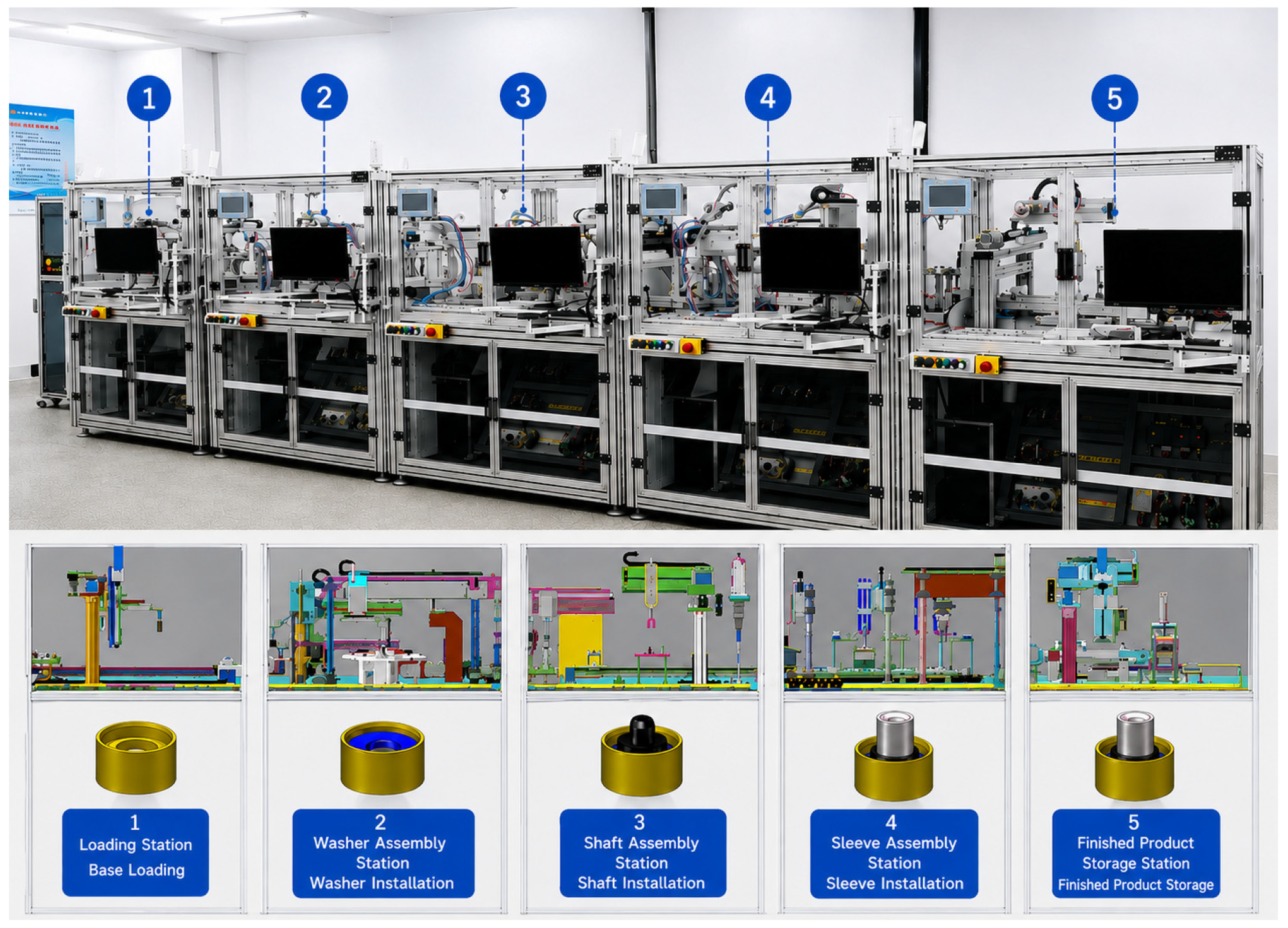
A discrete assembly experimental line was used as the research platform. It consists primarily of a PLC controller, feeding mechanism, washer-assembly mechanism, shaft-assembly mechanism, sleeve-assembly mechanism, finished-product storage mechanism, position sensors, industrial cameras, and an industrial computer. The line sequentially performs workpiece feeding, washer assembly, shaft assembly, sleeve assembly, and finished-product transfer. The PLC is responsible for actuator sequencing, interlock decisions, and process-step transitions, while the industrial cameras acquire the operating state of the physical workpiece.
To support PLC program virtual commissioning and virtual–physical stage consistency verification, a corresponding virtual model was constructed in Unity according to the equipment structure, process flow, and control logic of the physical line, as shown in Figure 1. The virtual model follows the station layout and assembly flow of the physical line. Each virtual mechanism corresponds to an actual process operation, including feeding, washer assembly, shaft assembly, sleeve assembly, and finished-product storage, thereby establishing structural mapping between physical equipment and virtual objects.
During virtual-twin construction, three-dimensional models of the principal mechanisms, actuating components, and workpieces were created in SolidWorks 2024, simplified for efficient rendering, and imported into Unity3D 2022.3.19f1c1. Unity organizes the virtual model according to the equipment hierarchy, kinematic relationships, and process flow of the physical line. Each movable object is assigned a unique Object Key that corresponds one-to-one with the Object Id in the PLC control data. Through this mapping, the PLC command, which comprises the stage index, target object, action type, and motion parameters, is converted into the corresponding virtual-object action, thereby converting control states into virtual execution behavior and providing the basis for virtual-stage generation.
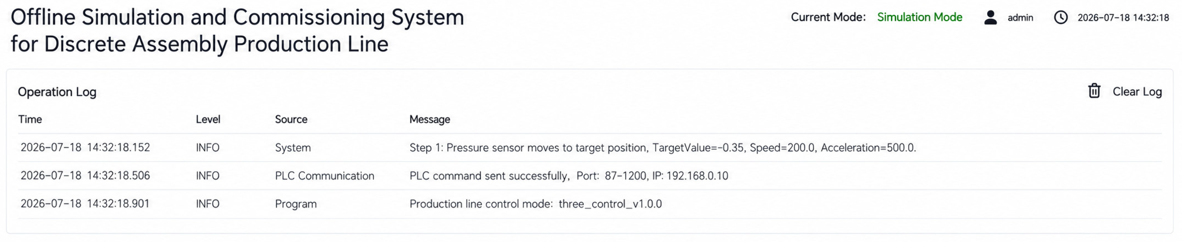
A simplified Unity-based virtual commissioning and state-monitoring interface was developed to support PLC program commissioning and the recording of virtual-execution information, as shown in Figure 2. The Operation Log records the issued PLC command, communication status, production-line control mode, and corresponding timestamps, thereby providing traceable execution information for PLC-to-Unity action mapping and subsequent virtual-stage generation.
Furthermore, to accommodate the coordinated execution of multiple actions during continuous assembly, the complete manufacturing process is decomposed into a series of stage units with explicitly defined start and end conditions. A state-machine-based stage transition mechanism is established to manage the progression between successive stages. Stage transitions are triggered according to the current process step and action-execution feedback. A new virtual execution stage S v ( t ) is generated only after the virtual object completes the target action and the control side confirms stage completion through the handshake mechanism. This mechanism prevents stage completion from being determined solely by PLC control commands, enabling the virtual execution stage to accurately reflect the actual execution status of the commanded action. Consequently, a reliable virtual-side reference is established for subsequent consistency verification against the corresponding vision-derived physical stage.

2.2. Structured Description of PLC Control States

To avoid directly processing numerous distributed PLC variables, the current PLC command is represented as a structured control state. The core variables and their meanings are listed in Table 2.
Step Index denotes the current process stage; Action Type distinguishes translation, rotation, waiting, and other action types; Object Id identifies the target mechanism or virtual object; and Axis, Target Value, and Speed specify the motion direction, target value, and execution speed, respectively. Action Finished indicates that the Unity object has completed the current action, whereas Step Done indicates that the PLC has confirmed the end of the current step and permits program advancement. These variables organize discrete PLC control information into a unified command structure for virtual-action parsing and stage synchronization.
The PLC control program was developed in TIA Portal V18 using sequential state control based on Step Index. Each process step includes an action output, completion condition, and timeout decision. After entering a step, the PLC writes the step index, target object, action type, and motion parameters to the communication data block. When Unity completes the corresponding action and returns Action Finished, the PLC sets Step Done and advances to the next step. If no completion feedback is received within the specified time, the PLC remains in the current step and logs a timeout fault, preventing premature program advancement.
After the PLC program was developed, offline PLC monitoring and joint PLC–Unity commissioning were performed to verify the control logic and state-variable design. During offline commissioning, S7-PLCSIM monitored Step Index, Action Type, Object Id, and related variables to check step-entry conditions, action outputs, exit conditions, and timeout logic. During joint commissioning, individual process steps were triggered while observing Unity object motion and changes in Action Finished and Step Done, with particular attention to premature step advancement, repeated feedback reading, and communication anomalies. These procedures ensured that the PLC control states correctly drove the virtual objects and provided a basis for subsequent virtual-stage generation and synchronization verification.

2.3. Mapping PLC Control States to Virtual Actions

A table-based mapping method using unique object identifiers, action-type encoding, and parameter-driven execution was adopted to convert PLC control states into Unity virtual actions. First, each movable object in the Unity scene was assigned a unique Object Key, and a mapping table between the PLC-side Object Id and the Unity Object Key was established. Second, Action Type was mapped to the corresponding execution script, and PLC parameters such as displacement, rotation angle, speed, and waiting time were used as script inputs, thereby converting PLC commands into specific virtual-object actions.
The Unity communication module periodically reads the PLC data block and validates Step Index, Object Id, Action Type, and the action parameters. After validation, Object Id is converted to a Unity Object Key through the mapping table, while Action Type and its parameters are encapsulated as a unified action request. The object manager locates the target object and invokes the corresponding execution script. To prevent repeated execution of the same command, Unity stores the most recently received Step Index and a command-valid flag, triggering an action only when the stage index changes or a new valid command is detected. Action completion is determined from the target-position error, target-angle error, or specified waiting time.
Through this mapping mechanism, the PLC stage index, object identifier, action type, and execution parameters are converted into the target object, action script, and motion parameters in Unity. Once the object reaches the target state, Unity updates the execution result, providing the basis for action-completion feedback and virtual-stage generation.

2.4. PLC–Unity Step Handshake Based on Action-Completion Feedback

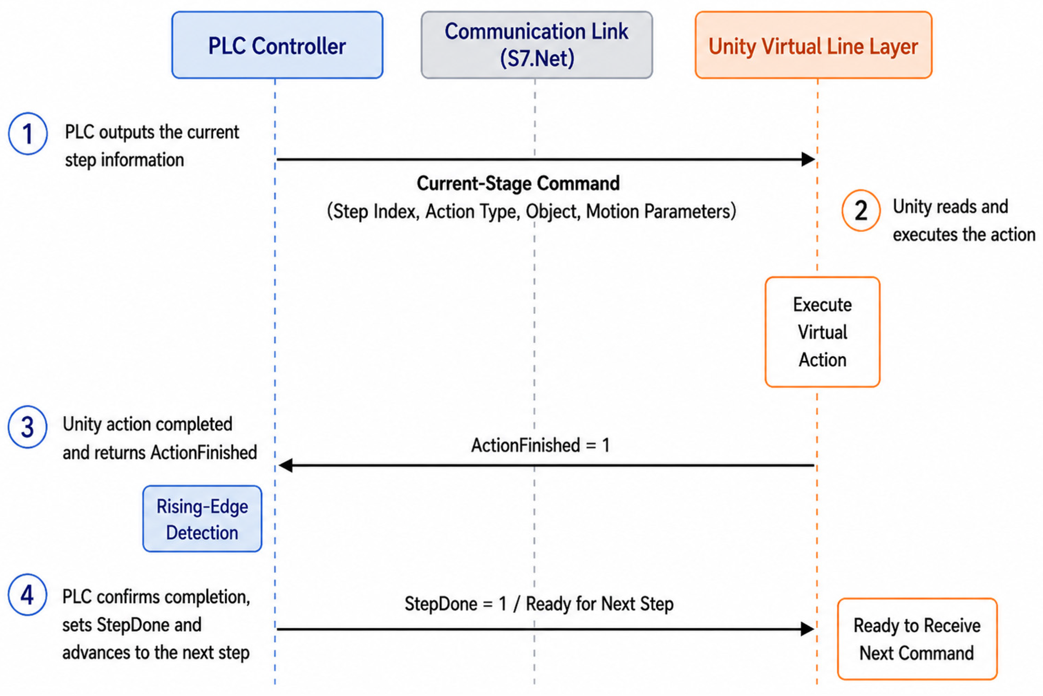
A one-way mapping from PLC variables to Unity actions may still cause stage desynchronization because of the communication cycle, animation execution time, or fixed delays. An Action Finished–Step Done dual-signal handshake was therefore designed, as illustrated in Figure 3.
After sending the current-stage command, the PLC holds Step Index unchanged. Unity detects the new command, executes the corresponding action, and sets Action Finished when the object reaches the target state. Upon detecting the rising edge of Action Finished, the PLC sets Step Done, advances to the next stage, and clears the current command. Unity resets Action Finished after detecting the stage update. If completion feedback is not received within the specified timeout period, the PLC suspends stage advancement and logs a timeout fault.
Action Finished indicates that the execution side has completed the current action, whereas Step Done indicates that the control side has confirmed the end of the current stage. Rising-edge detection, signal reset, and timeout handling prevent completion feedback from the previous stage from being incorrectly read by the next stage. Therefore, a virtual execution stage is not merely a PLC step that is “ready to execute”; instead, it represents a stage in which the PLC command has been executed in Unity and confirmed by the control side, and can thus serve as the virtual-side reference for comparison with the vision-derived physical stage.
For bilateral comparison, the term “stage” is defined as a process-level manufacturing milestone rather than an instantaneous actuator state. On the virtual side, a stage event is issued only after the final PLC-controlled action associated with that milestone has been completed in Unity and confirmed through the Action Finished–Step Done handshake. On the physical side, the corresponding stage event is issued when the detected workpiece is confirmed within the process region assigned to the same milestone. Thus, the two sides use different sensing and triggering mechanisms but share the same stage index and process meaning. Their timestamps are therefore compared as two observations of the same process milestone, not as timestamps of identical low-level motions.

2.5. Virtual Execution Stage Generation and Synchronization Performance

The virtual execution stage is jointly determined by the current PLC step, the Unity virtual-object execution result, and the step-handshake state. A step is marked as completed and the virtual execution stage is updated only after the target object finishes the current action, returns Action Finished, and the PLC confirms the stage through Step Done. PLC control-state mapping and PLC–Unity step-synchronization experiments were conducted to verify the correctness of virtual-side stage generation.

2.5.1. PLC Control-State Mapping Experiment

Translation, rotation, and waiting actions in the test-station process were repeatedly tested to verify PLC control-state mapping. The PLC output action type, target object, motion axis, and target parameters were recorded and compared with the Unity-side parsing result and final virtual object state. Mapping was considered successful when Unity correctly identified the action type and target object and drove the corresponding object to the target state. A total of 200 valid action-mapping samples were obtained, as summarized in Table 3.
As shown in Table 3, Action Types, Object Id, Axis, and the action parameters output by the PLC were correctly parsed by Unity in all 200 tests. The structured control state can therefore be stably converted into virtual actions and provides reliable input for action completion confirmation and virtual-stage generation.
Figure 4 presents the PLC control-state mapping experiment through the Operation Log. The log summarizes the translation, rotation, and waiting-action tests and reports the corresponding test counts, successful mappings, and overall mapping success rate. These records provide direct experimental evidence for the PLC-to-Unity action-mapping results summarized in Table 3.
The bilateral verification layer uses five process-level stage events (Start, Exec1, Exec2, Exec3, and End). Their boundaries are defined by representative PLC-controlled actions that correspond to observable process progression. A virtual-stage event is generated only after the corresponding boundary action has been completed and confirmed by the Action Finished–Step Done handshake, whereas the physical-stage event is generated after stable visual confirmation of the workpiece in the corresponding process region. Table 4 summarizes the representative boundary actions and the corresponding virtual and physical completion conditions.

2.5.2. PLC–Unity Step-Synchronization Experiment

The step-synchronization experiment recorded the times of PLC command reading, Unity-action completion, Action Finished write-back, and PLC stage advancement. A total of 100 stage transitions were completed, and the results are listed in Table 5.
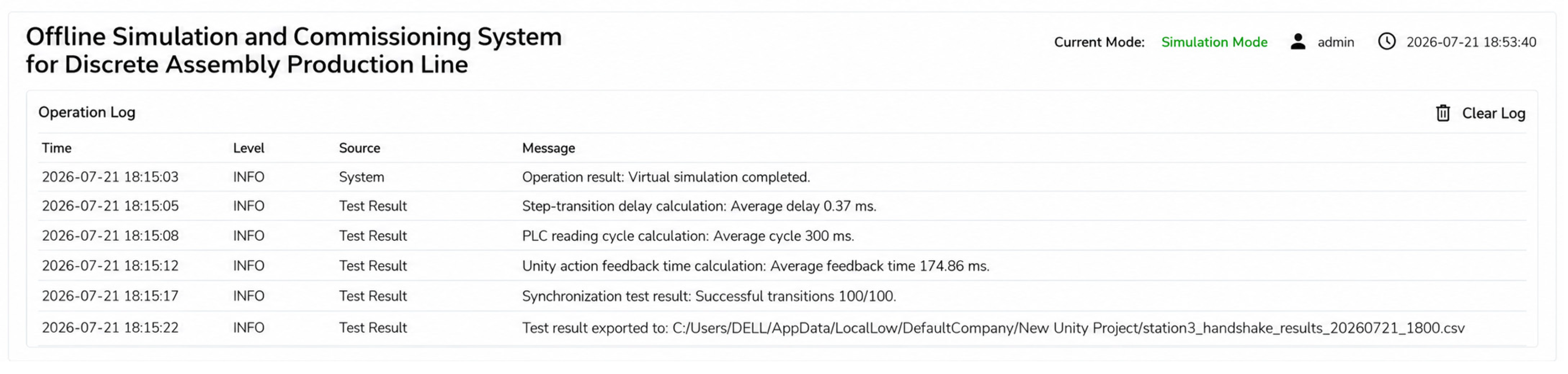
All 100 stage transitions advanced correctly only after the virtual action had completed and Action Finished had been returned; no repeated triggering or stage misalignment occurred. The average PLC-state reading cycle was 300 ms, the average feedback time after Unity-action completion was 174.86 ms, and the average delay from PLC feedback reception to entry into the next stage was 0.37 ms. These results demonstrate that the handshake mechanism synchronizes the PLC program with Unity actions, ensures that each virtual execution stage explicitly represents action completion, and provides stable virtual-side input for subsequent consistency comparison.
Figure 5 presents the PLC–Unity step-synchronization experiment through the Operation Log. The log records the step-switching delay, PLC variable-monitoring interval, Unity action-feedback interval, and batch-test result. These records provide traceable timing information for evaluating the PLC–Unity handshake and correspond to the synchronization results summarized in Table 5.

3. Machine-Vision Based Physical-Stage Perception

Section 2 established the mapping between PLC control states and virtual execution stages for the complete discrete assembly line. Because visual-stage perception at different stations follows similar technical logic, a representative test station with a long motion path, clear stage boundaries, and a complete start–execution–end process was selected for physical-stage perception and bilateral consistency verification in this paper. This station covers the key procedures of object detection, region determination, stage-event generation, and anomaly identification. For other stations, the same method can be applied by reconfiguring the camera coverage, process regions, and stage-transition rules according to their process paths.

3.1. Physical-Workpiece Image Acquisition and Object Detection

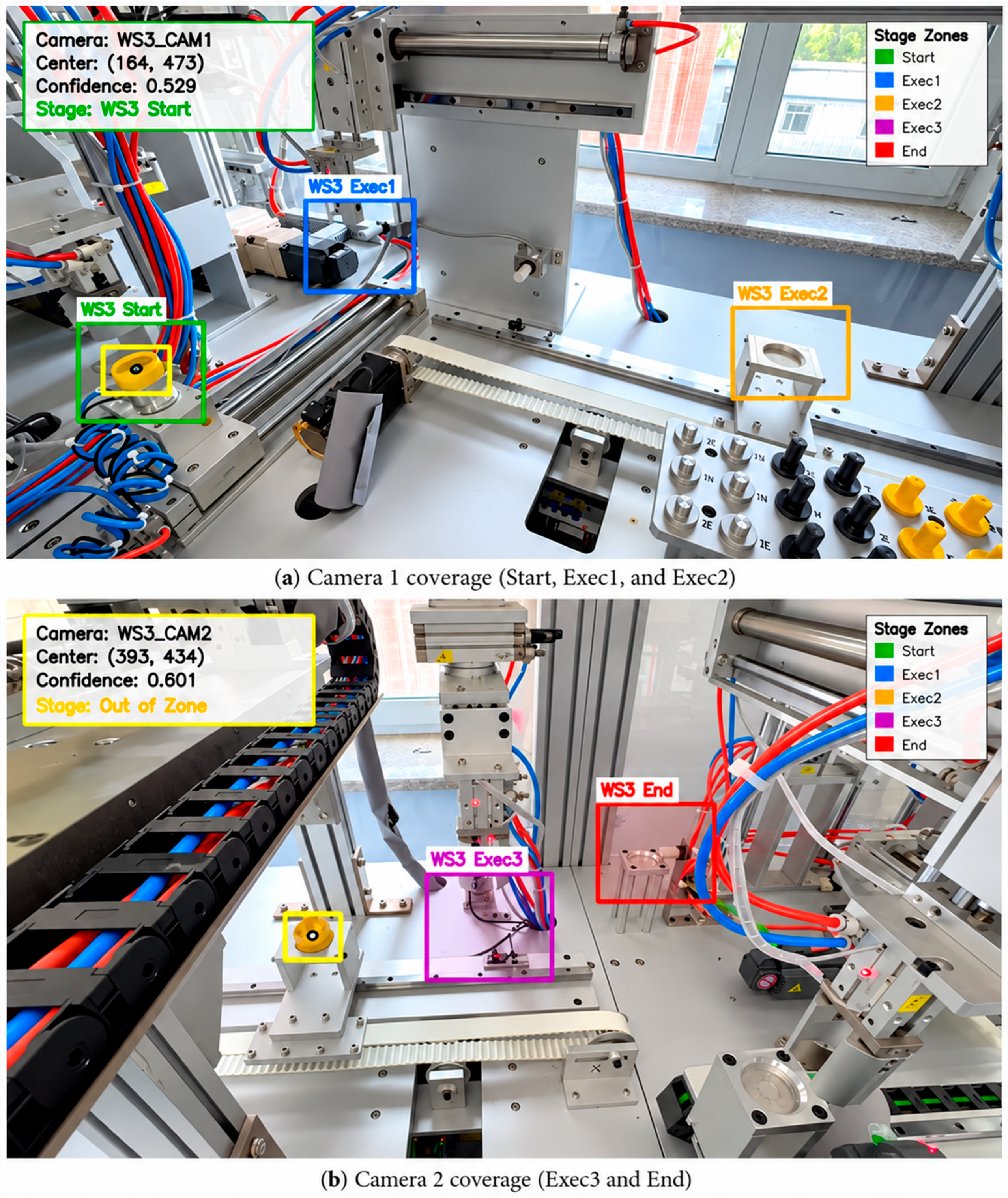
Because the workpiece path at the selected station is too long to be fully covered by a single camera, two Hikvision MV-CS060-10GC industrial cameras (Hikvision, Hangzhou, China) were used for partitioned acquisition. The image resolution was 1280 × 720 at 30 fps. Camera 1 covered the Start, Exec1, and Exec2 regions, while Camera 2 covered Exec3 and End, thereby providing continuous observation of the complete process path.
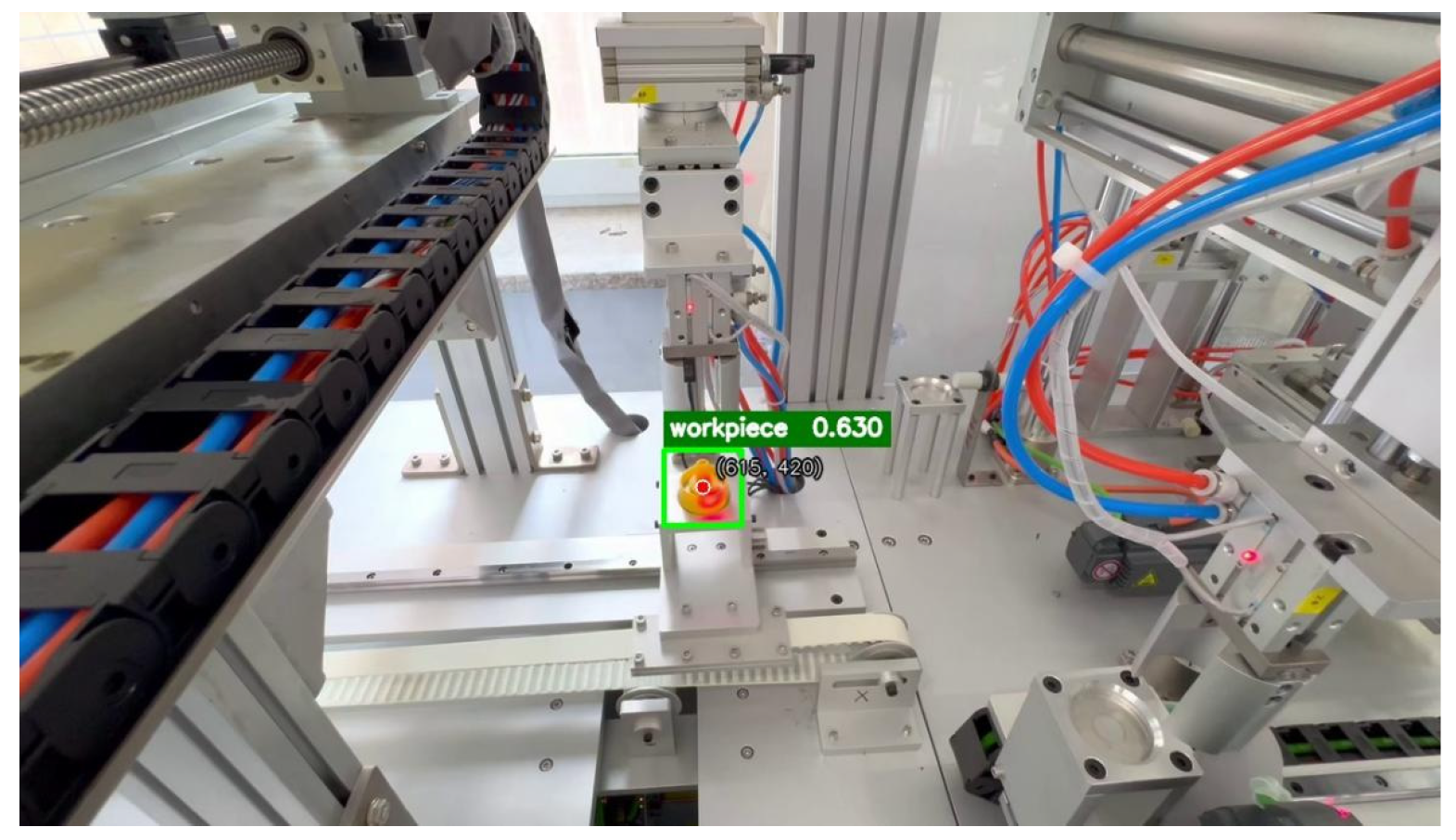
The acquisition program uses the camera SDK for device connection, image capture, and format conversion, and supplies real-time visual information for physical workpiece state perception. To balance detection accuracy and real-time performance for workpiece recognition and assembly-process monitoring, YOLO11 was used for workpiece localization. The visual module adopts a latest-frame processing strategy: the currently available image is input to the model to obtain the bounding-box position and confidence, and the bounding-box center is calculated as the spatial basis for subsequent process region assignment. An object detection example is shown in Figure 6.

3.2. Process-Region Partitioning and Stage Mapping

According to the workpiece trajectory and process-action boundaries at the selected station, five process regions—Start, Exec1, Exec2, Exec3, and End—were defined, as shown in Figure 7. The system calculates the bounding-box center and determines its process region according to the camera identifier. When the center enters a target region, a candidate stage event is generated. To suppress boundary jitter and single-frame false detections, two consecutive valid detections are required: entry into a stage is confirmed only when two consecutive detections fall within the same region. The interval between adjacent valid detections is approximately 65.3 ms, dominated by image preprocessing, model inference, and postprocessing. Thus, this confirmation mechanism reduces the influence of single-frame fluctuations while introducing only a small additional stage-recognition delay.

3.3. Generation of Vision-Derived Physical-Stage Events

Events from the two cameras are mapped to the same stage indices and sorted by industrial-computer timestamps. The process-transition rule distinguishes valid stage progression from abnormal transition candidates. Adjacent transitions in the order Start → Exec1 → Exec2 → Exec3 → End are accepted as valid progression. A detected nonadjacent transition is not silently discarded; instead, it is retained with an invalid-transition flag and forwarded to the bilateral consistency-verification module, where it can be reported as an invalid stage transition. To avoid repeated event output while a workpiece remains in the same region, the event cooldown for a stage was set to 1.5 s according to the station cycle and adjacent-stage transition interval. The same valid stage cannot be triggered repeatedly during the cooldown period. If multiple valid candidate events occur simultaneously in a handover region, the event satisfying the expected adjacent-transition relationship and having the earliest timestamp is retained.
A vision-derived physical-stage event contains fields such as station identifier, stage index, timestamp, detection confidence, and transition-validity status. Consecutive-frame confirmation suppresses single-frame detection fluctuations, the transition rule labels nonadjacent candidates instead of removing the evidence needed for anomaly classification, and event cooldown prevents repeated triggering of the same valid stage. Through these procedures, instantaneous detections are converted into stage events with process semantics and temporal attributes while abnormal transition evidence remains available to Section 4.3.

3.4. Validation of the Vision-Derived Physical-Stage Perception Method

The proposed vision-derived physical-stage perception method was evaluated from three perspectives: object detection, stage-event generation, and strategy ablation. First, the workpiece detection performance of YOLO11 was assessed. Second, the accuracy and real-time performance of converting detections into visual-stage events were evaluated. Finally, ablation experiments analyzed the effects of consecutive-frame confirmation and valid stage-transition constraints on event-generation performance.

3.4.1. Object-Detection Experiment

The dataset comprised 1237 images collected during operation of the physical line, including 1003 training images and 234 validation images. The training set contained 632 annotated workpiece boxes and the validation set contained 194. Images without workpiece boxes were intentionally retained as negative/background samples; they expose the detector to fixtures, mechanisms, and empty process regions and therefore help suppress false positive workpiece detections. To reduce data leakage caused by the high similarity of consecutive video frames, the training and validation sets were divided by complete operating runs. The 30 complete runs used for the stage-event experiment in Section 3.4.2 were acquired as separate operating sequences and were not included in the detector training or validation split. The evaluation metrics were Precision, Recall, mAP@0.5, mAP@0.5:0.95, and per-frame processing time.
For reproducibility, the detector-training configuration is summarized in Table 6. The experiment used YOLO11n implemented with Ultralytics 8.3.9, initialized from yolo11n.pt, with an input size of 640 × 640, 100 training epochs, and a batch size of 8. The optimizer setting used the implementation’s automatic configuration. The resulting object-detection performance is summarized in Table 7.
YOLO11 achieved a Recall of 0.9689 and an mAP@0.5 of 0.9021, satisfying the requirements for workpiece detection and center-point localization. The total preprocessing, inference, and postprocessing time was approximately 65.3 ms per frame, corresponding to an effective processing rate of about 15.3 fps.
Because this processing rate is lower than the camera acquisition rate of 30 fps, the visual program does not accumulate historical images. Instead, after processing the current frame, it directly reads the latest image in the buffer to avoid continuously increasing latency. Stage perception depends on the sustained presence of the workpiece in key regions and does not require inference on every acquired frame. At the current station cycle, the dwell time in each region covers two consecutive inferences, so 15.3 fps is sufficient for online stage-event generation.
The mAP@0.5:0.95 value of 0.4369 indicates that bounding-box boundaries still fluctuate under strict IoU thresholds. However, the proposed method assigns regions using the bounding-box center and therefore depends less on exact box overlap. Instantaneous deviations near region boundaries are further mitigated by consecutive-frame confirmation and stage-transition constraints.

3.4.2. Visual-Stage Event Experiment

To evaluate the conversion of detections into process-stage events, 30 complete process runs were performed on the physical line. Each run sequentially passed through Start, Exec1, Exec2, Exec3, and End, producing 150 ground-truth stage events. Line video and visual-program event logs were saved synchronously, and correct, false, and missed events were determined by manual frame-by-frame review. The results are presented in Table 8.
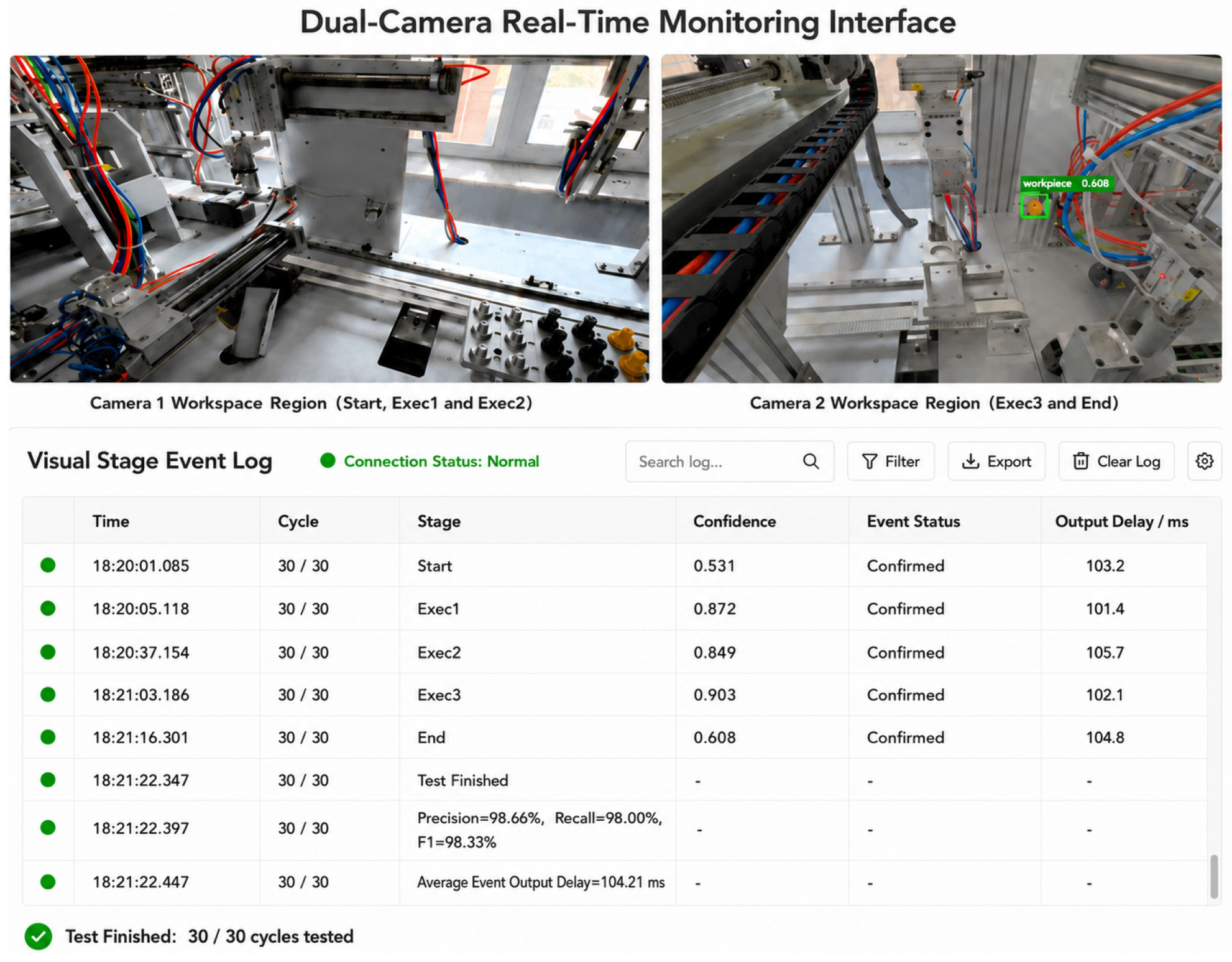
Across the 30 runs, the visual program output 149 events, 147 of which matched the manually annotated stages and sequence, with two false events and three missed events. False events occurred mainly when the workpiece center approached a region boundary. Missed events were primarily associated with brief occlusion, insufficient detection confidence, or a short dwell time in the target region. Event-level Precision, Recall, and F1-score were 98.66%, 98.00%, and 98.33%, respectively, and the average event-generation latency was 104.21 ms.
Figure 8 shows an example of dual-camera visual-stage recognition and the corresponding Operation Log. The upper portion presents real-time views from the two cameras: Camera 1 covers the workpiece motion range corresponding to Start, Exec1, and Exec2, while Camera 2 covers Exec3 and End. The lower portion shows the visual-stage event log, which records the run index, stage label, detection confidence, event-confirmation status, and output latency, thereby illustrating the online conversion of physical-workpiece detections into structured visual-stage events.
These results show that object detection provides reliable positional input for process-region determination, while consecutive-frame confirmation, valid stage-transition constraints, and event cooldown suppress single-frame fluctuations, repeated triggers, and invalid events. The resulting pipeline—object detection, region mapping, and temporal confirmation—converts physical workpiece positions into stable stage events with explicit process semantics, thereby providing reliable physical-side input for virtual–physical consistency verification.

3.4.3. Ablation Study of the Stage-Event Generation Strategy

To analyze the effects of consecutive-frame confirmation and valid stage-transition constraints, an ablation study was performed using the 30 complete process runs from Table 8. Three settings were compared: the complete method, removal of consecutive-frame confirmation, and removal of the valid stage-transition constraint. All settings used the same YOLO11 model, process region partitioning, detection-confidence threshold, and event cooldown; only the corresponding event-generation strategy was changed. Manual frame-by-frame annotations were used as the reference ground truth. The results are listed in Table 9.
As shown in Table 9, the complete method achieved the best overall recognition performance, with event-level Precision, Recall, and F1 values of 98.66%, 98.00%, and 98.33%, respectively.
After consecutive-frame confirmation was removed, the number of correct events increased to 149 and missed events decreased to one, raising Recall from 98.00% to 99.33%. This indicates that single-frame triggering can reduce misses caused by short workpiece dwell times. However, without consecutive-frame consistency verification, instantaneous detection fluctuations and false detections near region boundaries more readily generated events. The number of false events therefore increased from two to ten, Precision decreased to 93.71%, and F1 decreased to 96.43%. Thus, although consecutive-frame confirmation can introduce a small number of missed events, it substantially suppresses detection jitter and improves event-generation stability.
After the valid stage-transition constraint was removed, correct events decreased to 144, while false and missed events increased to seven and six. Precision, Recall, and F1 decreased to 95.36%, 96.00%, and 95.67%, respectively. Without the process-order constraint, false detections in handover regions more easily produced nonadjacent-stage events, and abnormal events could disrupt the subsequent stage sequence and increase misses. The valid stage-transition constraint therefore uses process-flow prior knowledge to filter candidates that violate stage-evolution rules and improves event-sequence completeness and consistency.
Overall, consecutive-frame confirmation and the valid stage-transition constraint improve event-generation quality from the perspectives of temporal continuity and process-logic consistency, respectively. The former suppresses instantaneous detection fluctuations, while the latter constrains stage-evolution order. Their combined effect enables visual detections to be stably converted into stage events with unified process semantics.

4. System Integration and Comprehensive Virtual–Physical Consistency Verification

4.1. System Integration and Verification Procedure

Building on virtual-stage generation and vision-derived physical-stage perception, an integrated PLC–Unity–vision verification system was developed. The system receives execution-confirmed virtual-stage events and vision-derived physical-stage events and performs temporal alignment, stage matching, and anomaly assessment using unified process-stage semantics and a common time base.
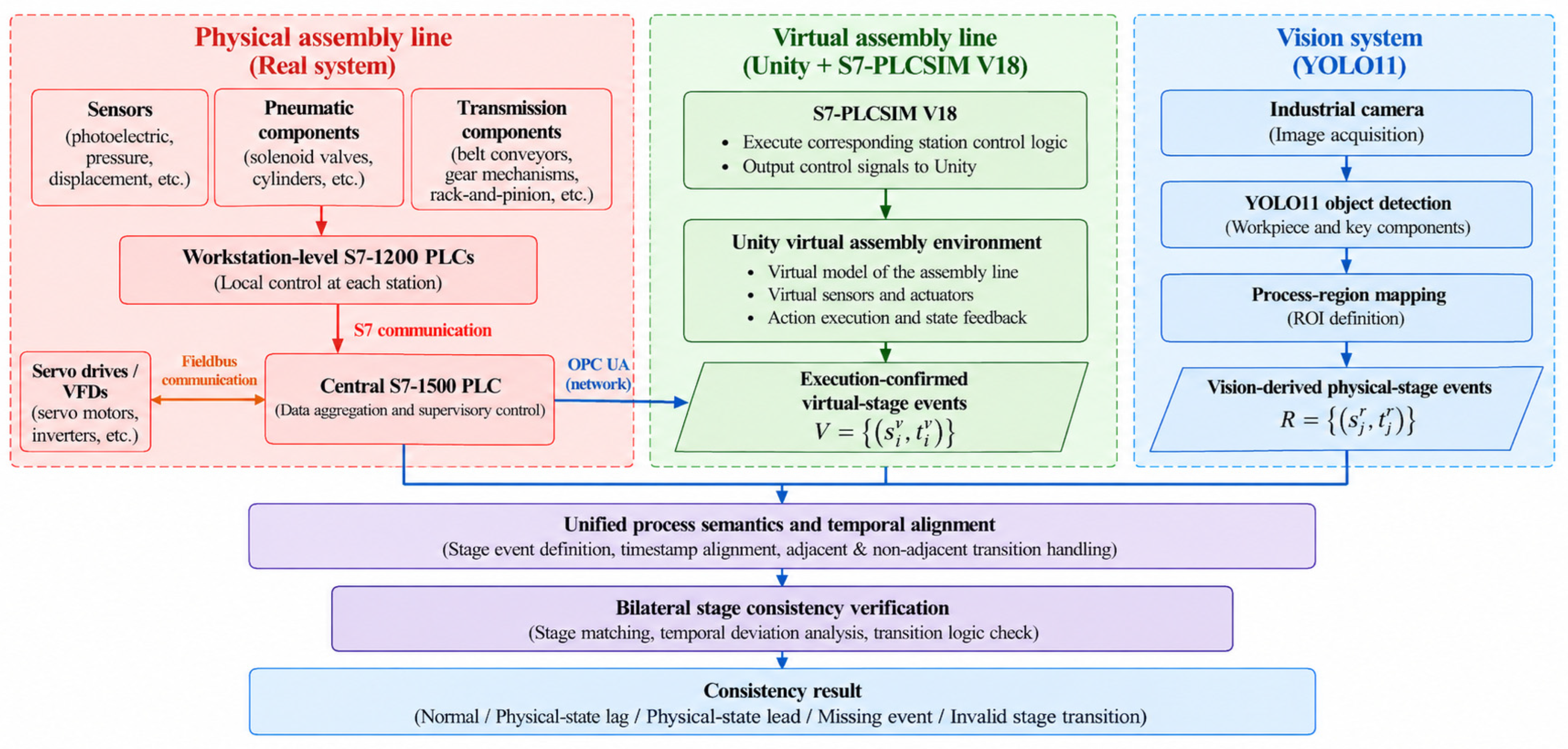
As shown in Figure 9, the verification system consists of a virtual-execution branch, a physical-execution branch, and a bilateral stage-consistency verification module. The virtual branch executes the station control logic in S7-PLCSIM V18 and communicates with Unity through NetToPLCsim/S7.Net. The physical production line adopts a hierarchical PLC control architecture. Sensors, pneumatic components, and transmission components at each workstation are connected to local Siemens S7-1200 PLCs through their corresponding interfaces and protocols. The workstation-level S7-1200 PLCs communicate with a central Siemens S7-1500 PLC through S7 communication. Servo drives and variable-frequency drives are connected to the central S7-1500 through the corresponding fieldbus and provide motor operating-status information. The central S7-1500 aggregates the physical-line process and status data, which are transmitted to Unity over the network through OPC UA. Industrial cameras independently observe the workpiece trajectory. The virtual and physical branches follow the same prescribed process sequence and unified stage definitions, and their independently generated stage events are aligned using a common process start and industrial-computer time base.
System verification was conducted at three levels. First, the mapping of PLC control states to Unity actions and handshake-based virtual-stage generation was verified. Second, the conversion of physical workpiece positions into stage events by the visual module was evaluated. Third, virtual and physical stages were compared under normal and abnormal conditions to validate the consistency-decision logic.

4.2. Experimental Platform and Parameter Settings

Experiments were conducted over the complete process of the representative station on the discrete assembly line. The PLC program was developed in TIA Portal V18. For the virtual-commissioning branch, the corresponding station control logic was executed in S7-PLCSIM V18 and communicated with Unity through NetToPLCsim and S7.Net. The physical line was operated by its original hierarchical PLC control system, in which workstation-level Siemens S7-1200 PLCs communicated with a central Siemens S7-1500 PLC through S7 communication, while servo drives and variable-frequency drives communicated with the central controller through the fieldbus. The aggregated physical-line process and status data were transmitted from the central S7-1500 to Unity through OPC UA, and two industrial cameras independently observed the physical workpiece. YOLO11 inference was performed on a CPU platform. Both branches followed a common process start and a common industrial-computer time base; their independently generated virtual-stage and physical-stage events were then compared. Virtual-stage generation, physical-stage event output, and bilateral stage comparison were evaluated separately. The main configuration is listed in Table 10.

4.3. Virtual–Physical Consistency Verification Experiment

The system separately maintains the virtual execution stage Sv(t) and the vision-derived physical stage Sr(t). The virtual execution stage Sv(t) is jointly generated through PLC state mapping, virtual-object action execution, and the step handshake mechanism. The Unity virtual commissioning interface records the corresponding stage-completion time tv, indicating that the PLC command has been executed by the virtual object and the completion state has been confirmed through the handshake mechanism. The vision-derived physical stage Sr(t) is generated through industrial-camera image acquisition, YOLO11 object detection, process-region determination, and consecutive-frame confirmation. The industrial computer records the corresponding confirmation time tr, indicating that the physical workpiece has reached the corresponding process region and that the physical-stage event has been confirmed by the vision pipeline. Both the virtual and physical sides use Start, Exec1, Exec2, Exec3, and End to represent the process progression of the test station, thereby establishing unified stage semantics.
It should be noted that tr is the confirmation timestamp of the vision-derived physical-stage event rather than the exact occurrence time of the underlying mechanical state transition. It therefore includes the latency associated with image acquisition, YOLO11 inference, process-region mapping, and consecutive-frame confirmation. Consequently, the difference tr − tv used in this study represents an end-to-end bilateral stage-observation difference rather than a pure mechanical physical-state delay. If intrinsic mechanical delay needs to be isolated more accurately, the image-acquisition timestamp may be propagated through the perception pipeline, or the measured perception latency may be calibrated and compensated for. The present study retains tr because its objective is bilateral stage-consistency verification rather than intrinsic mechanical-delay identification.
To ensure temporal comparability between the virtual execution stage and the vision-derived physical stage, the Unity virtual-execution module, vision-event generation module, and consistency-evaluation module use a common timing service provided by the industrial computer. At the beginning of each experimental run, the timer is reset, and the start of the run is defined as t = 0. On the Unity side, the virtual-stage generation time tv,i,j is recorded after the virtual object completes the current action, the Action Finished signal is asserted, and the PLC confirms completion through the Step Done handshake. On the vision side, the vision-derived physical-stage generation time tr,i,j is recorded after the workpiece satisfies the object-detection, process-region determination, consecutive-frame confirmation, and valid stage-transition conditions. Here, i denotes the process-stage index, and j denotes the experimental-run index.
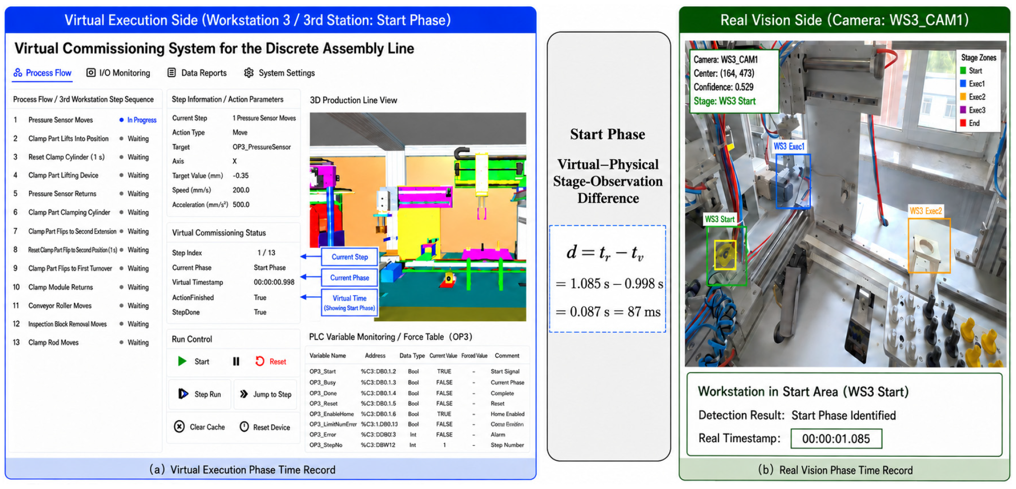
To illustrate the temporal correspondence between the virtual and vision-derived physical stages, a representative stage from a normal run was compared, as shown in Figure 10. The left panel presents the Unity virtual commissioning interface, including the current process step, virtual-stage state, and stage-completion time. The right panel shows the physical workpiece captured by the industrial camera together with the corresponding stage-confirmation time obtained through visual detection. The middle panel summarizes the timestamp recording and the stage-observation difference calculation. For the Start stage, the virtual execution stage was completed at 0.998 s, whereas the visual system detected the workpiece in the corresponding region and confirmed the event through consecutive frames at 1.085 s, yielding a time difference of 87 ms. This example illustrates timestamp recording and time-difference calculation for a single run; the statistics in Table 11 are based on 30 normal runs.
To compensate for normal time differences caused by mechanism motion, PLC–Unity communication, visual inference, and program scheduling, an allowable time window was introduced for bilateral stage comparison. To determine this window, the virtual-stage generation time and the vision-derived physical-stage generation time for the same process stage were recorded over 30 normal runs, and the time difference between the corresponding virtual and physical stages was calculated as follows:
d i , j = t r , i , j − t v , i , j
where i denotes the process-stage index, j denotes the experimental-run index, tv,i,j is the generation time of the i-th virtual execution stage in the j-th run, tr,i,j is the confirmation time of the corresponding vision-derived physical stage, and di,j is the bilateral stage-observation difference. When di,j > 0, the physical-stage event is confirmed later than the corresponding virtual-stage event; when di,j < 0, it is confirmed earlier. The lag/lead classification is determined using the decision thresholds defined below rather than by the sign alone.
The 30 normal runs were statistically analyzed to obtain, for each stage, the mean virtual-stage generation time, mean vision-derived physical-stage generation time, mean time difference, and standard deviation of the time difference, as listed in Table 11. These quantities were calculated using the following expressions:
t ¯ v , i = 1 n ∑ j = 1 n t v , i , j
t ¯ r , i = 1 n ∑ j = 1 n t r , i , j
d ¯ i = 1 n ∑ j = 1 n d i , j
s d i = 1 n − 1 ∑ j = 1 n d i , j − d ¯ i 2
where n denotes the total number of normal experimental runs, with n = 30.
Table 11 shows that the vision-derived physical stage generally occurred later than the corresponding virtual execution stage during normal operation. The mean time difference across the five stages ranged from 86 to 153 ms. Exec2 had the largest mean difference of 153 ms, while Start had the smallest difference of 86 ms. These positive differences reflect the combined effects of physical mechanism motion, image acquisition, YOLO11 inference, process-region mapping, consecutive-frame confirmation, and communication/program scheduling. Therefore, they represent end-to-end stage-observation differences rather than intrinsic mechanical response delays. Because a vision-derived physical stage is generated only after the workpiece actually enters the target region and the visual event is confirmed, its later occurrence is reasonable.
To define an engineering tolerance for the implemented verification system, a candidate allowable time window was calculated for each stage as the observed mean stage-event time difference plus three sample standard deviations. In this paper, mean + 3 standard deviations is used as a conservative empirical margin; it is not interpreted as a normal-theory confidence interval, because only 30 normal runs were available and the distribution shape was not established. The resulting stage-specific candidate bounds were then compared.
Δ t i = d i + 3 s d i
Using the data in Table 11, the candidate allowable windows for the five stages were calculated as follows:
Δ t S t a r t = 86 + 3 × 9.8 = 115.4   m s
Δ t E x e c 1 = 125 + 3 × 14.3 = 167.9   m s
Δ t E x e c 2 = 153 + 3 × 17.6 = 205.8   m s
Δ t E x e c 3 = 115 + 3 × 13.2 = 154.6   m s
Δ t E n d = 145 + 3 × 15.9 = 192.7   m s
The candidate windows differed among stages, with Exec2 having the largest value of 205.8 ms. Stage-specific windows could retain more timing sensitivity, but they would also introduce five separately calibrated parameters from a limited calibration sample. For the present feasibility experiment, the maximum observed candidate bound was therefore selected and rounded upward to the nearest 10 ms, yielding a single conservative 210 ms window. This unified setting simplifies the decision logic and ensures that all five stage-specific candidate bounds are covered. The 210 ms value should be regarded as a platform-specific engineering tolerance rather than a universal threshold; stage-specific or adaptive windows are an important direction for larger datasets.
Δ t = max i Δ t i ≈ 210   m s
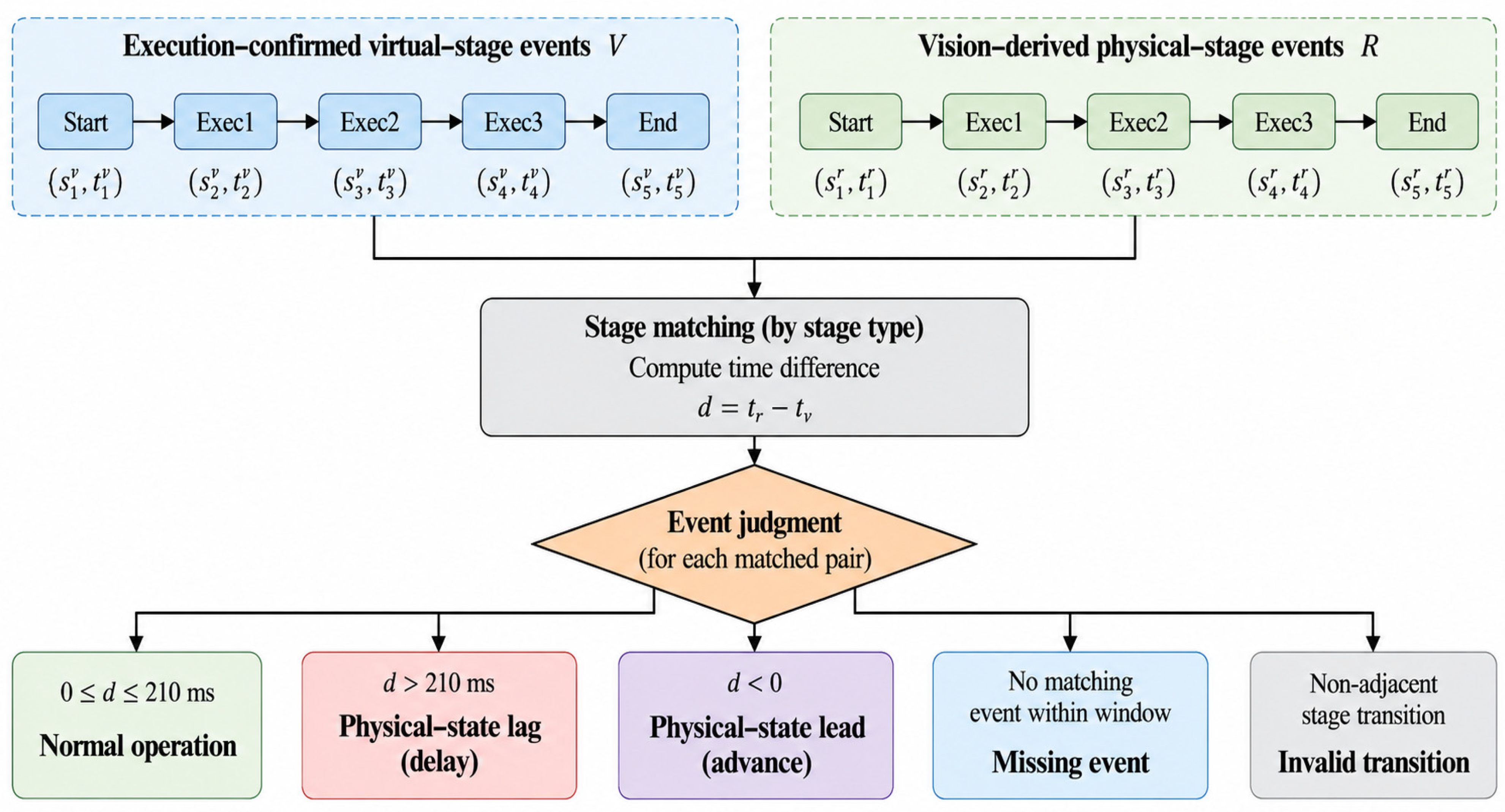
When a vision-derived physical-stage event completed a valid transition and satisfied 0 ≤ tr − tv ≤ 210 ms relative to the corresponding virtual-stage event, the bilateral timing relation was regarded as normal. A negative difference (tr − tv < 0) indicates physical-state lead, whereas a difference greater than 210 ms indicates physical-state lag. The detailed decision procedure is shown in Figure 11.
The same 30 normal runs were used to estimate the timing statistics in Table 11 and to report the 30/30 normal decisions in Table 12. Therefore, the normal row of Table 12 is a consistency check of the calibrated decision rule on the calibration data and should not be interpreted as an independent estimate of generalization performance. The controlled abnormal cases test the implemented classification logic under predefined injections. An independent normal-operation validation set will be required in future work for an unbiased estimate of threshold generalization.
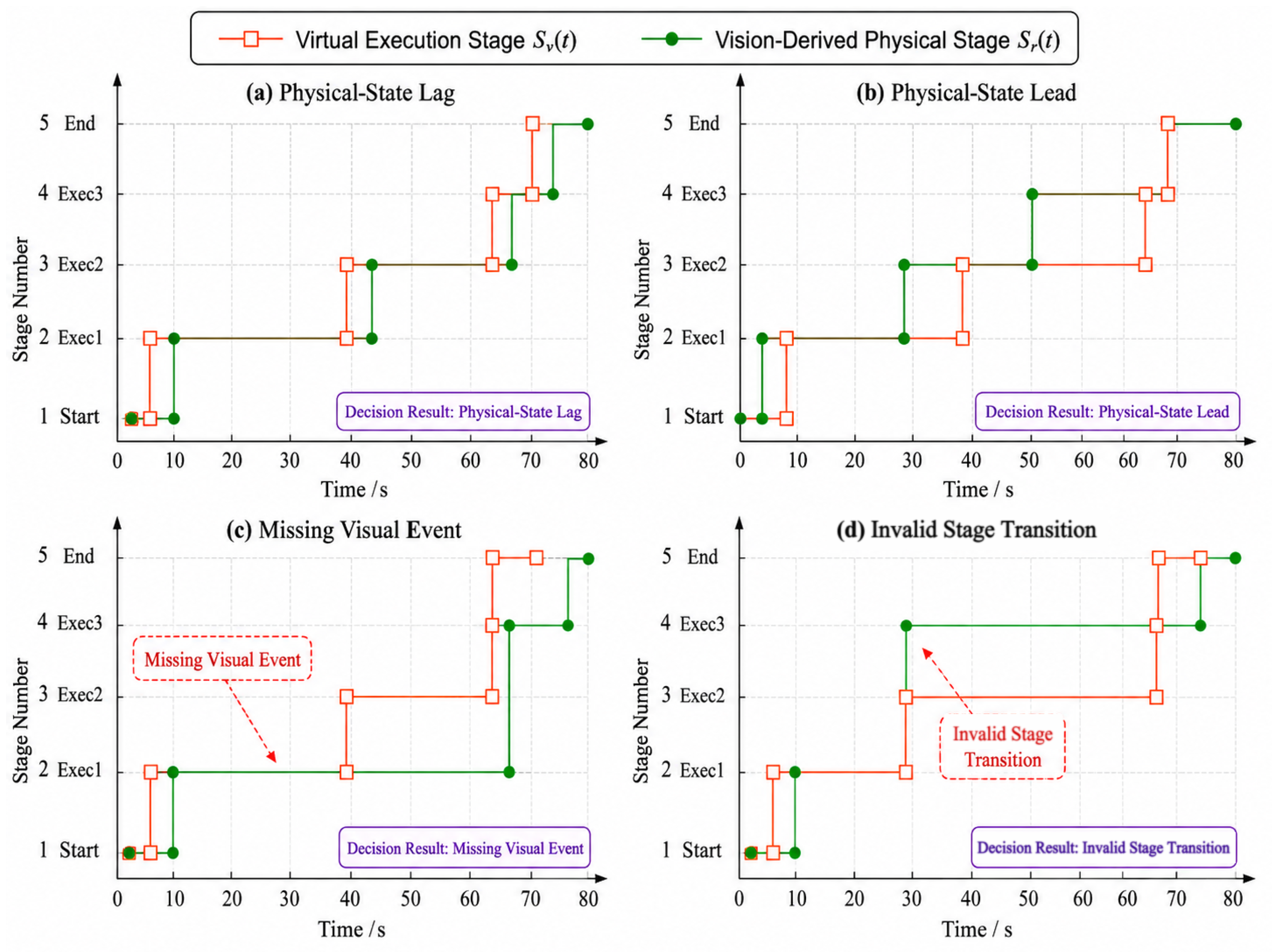
Controlled anomaly injection was used to validate the consistency-classification logic, that is, to determine whether the system could correctly classify each predefined anomaly pattern. This experiment does not demonstrate detection or generalization for every naturally occurring anomaly on an industrial line; such capability requires long-term operation and more real-world fault samples. Five scenarios were configured: normal operation, physical-state lag, physical-state lead, missing visual events, and invalid stage transitions. Under normal operation, the two sides remained synchronized. In the lag scenario, the virtual execution stage advanced while the physical workpiece remained in the previous stage. In the lead scenario, the vision-derived physical stage entered the next valid stage before the corresponding virtual execution stage advanced. Missing events were created by occluding the workpiece or discarding a specified event, and invalid transitions were created by injecting nonadjacent-stage events. The results are presented in Table 12.
For the invalid-transition scenario, a nonadjacent vision-stage candidate is intentionally injected or produced. As clarified in Section 3.3, this candidate is retained with an invalid-transition flag and passed to the consistency-decision layer; it is not accepted as the new valid physical stage. The decision layer then reports an invalid stage transition. Figure 11 explicitly shows this logic by classifying a nonadjacent stage transition as an invalid transition rather than accepting it as a valid physical-stage update.
Under the predefined normal and controlled abnormal conditions, 140 stage-consistency decisions were completed, and every system output agreed with the corresponding predefined class. The decision program therefore correctly classified normal consistency, physical-state lag, physical-state lead, missing visual events, and invalid stage transitions in the controlled test scenarios.
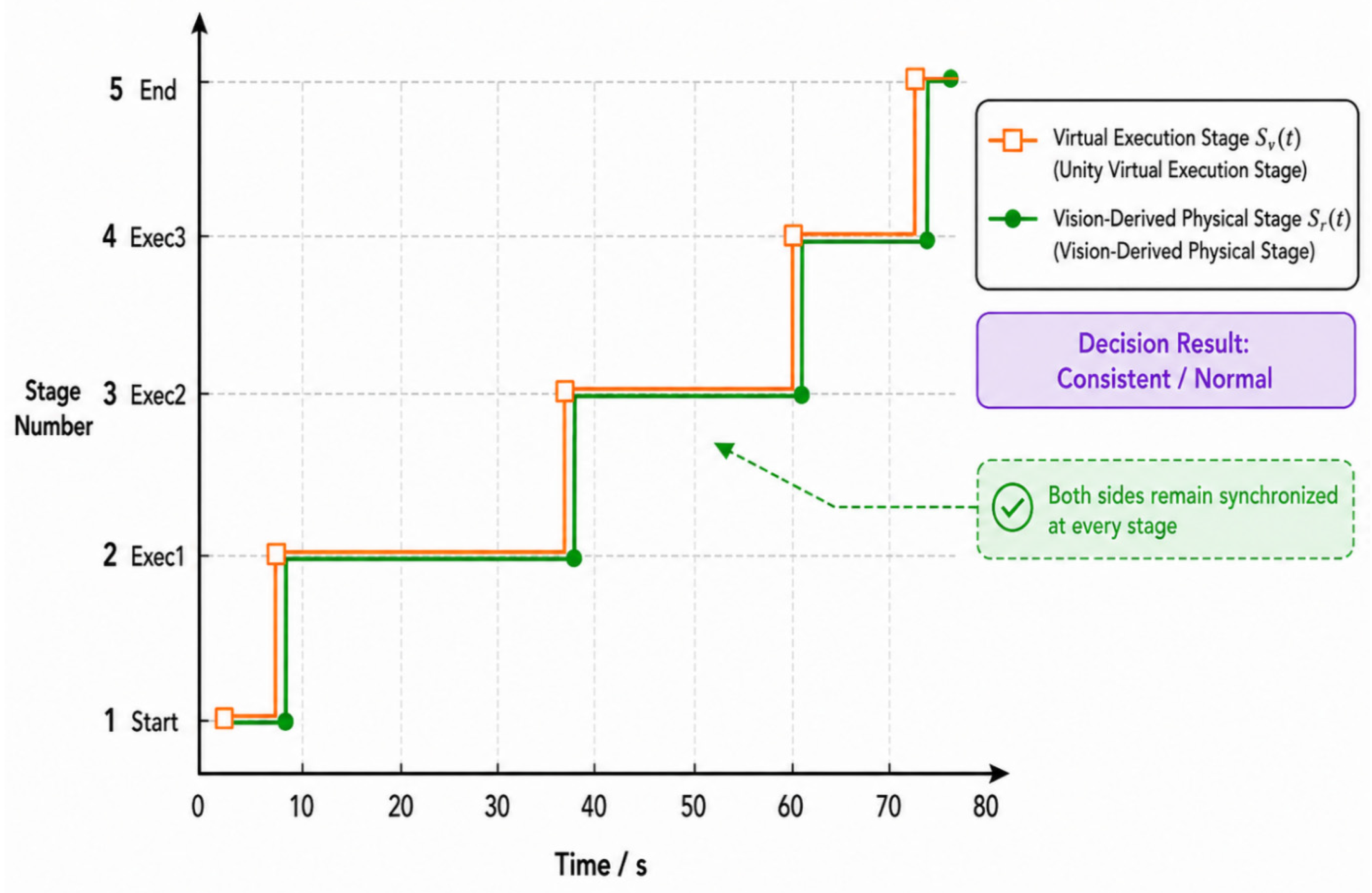
Under normal operating conditions, the virtual execution stage S v ( t ) and the vision-derived physical stage S r ( t ) remain approximately synchronized within the allowable time window, as illustrated in Figure 12. Under abnormal operating conditions, the bilateral stage trajectories exhibit four representative patterns—physical-state lag, physical-state lead, missing visual events, and invalid stage transitions—as shown in Figure 13.

4.4. Discussion

The action-mapping and step-handshake experiments demonstrate that the virtual execution stage is not a simple reflection of PLC command issuance; rather, it is an execution-completion state integrating the PLC control state, virtual-object action result, and control-side confirmation. The Action Finished–Step Done dual-signal handshake prevents the PLC from advancing before the virtual object completes its action, allowing the virtual execution stage to serve as a reliable reference for comparison with the vision-derived physical stage.
The physical-side experiments show that object detections become stable process-stage events only after process-region mapping, consecutive-frame confirmation, and valid stage-transition constraints are applied. The ablation study further confirms that consecutive-frame confirmation suppresses detection fluctuations near region boundaries, while valid transition constraints filter abnormal events that violate process order. Together, these strategies improve the stability of visual-stage events.
During normal operation, the observed vision-derived physical-stage event occurred 86–153 ms after the corresponding virtual execution stage. This positive offset reflects both physical-process timing and the implemented perception/confirmation pipeline and should not be interpreted as pure mechanical delay. A unified 210 ms engineering tolerance was obtained from the maximum of the five mean-plus-three-sample-standard-deviation candidate bounds and rounded upward. Because the same 30 normal runs were used for calibration and the normal-rule consistency check, the present experiment demonstrates feasibility on the current platform but does not provide an independent estimate of threshold generalization.
The controlled-anomaly experiments show that unified stage semantics transform deviations among PLC control states, virtual execution results, and physical workpiece states into process-meaningful stage relationships, enabling effective classification of consistency, physical-state lag, physical-state lead, missing visual events, and invalid stage transitions.
The experiments primarily verify feasibility on the present platform under a single-workpiece, fixed operating-path condition and controlled anomalies. They do not cover parallel multi-workpiece operation, severe occlusion, rework paths, or long-term continuous operation. Future work will investigate workpiece identity association, multi-object stage tracking, adaptive time windows, and dynamic process modeling to improve applicability in complex industrial environments.

5. Conclusions

To address the lack of a unified verification mechanism among PLC control states, virtual execution results, and physical workpiece states during virtual commissioning of discrete assembly lines, this paper proposed a PLC–vision-derived bilateral stage consistency verification method. Structured PLC control states are first mapped to Unity virtual-object actions, and execution-confirmed virtual execution stages are generated through the Action Finished–Step Done dual-signal handshake. YOLO11 detections are then combined with process-region mapping, consecutive-frame confirmation, and valid stage-transition constraints to generate vision-derived physical-stage events with process semantics and temporal attributes. Finally, virtual execution stages and vision-derived physical stages are bilaterally compared using unified stage indices and an allowable time window.
Experimental results show that all 200 PLC action mappings were completed correctly, and no repeated triggering or stage misalignment occurred during 100 PLC–Unity step transitions; the average step-transition delay was 0.37 ms. Event-level Precision, Recall, and F1 for visual-stage recognition were 98.66%, 98.00%, and 98.33%, respectively, with an average event-generation latency of 104.21 ms. Across 140 consistency decisions under five predefined conditions—normal operation, physical-state lag, physical-state lead, missing visual events, and invalid stage transitions—all system outputs agreed with the predefined condition labels. The normal-operation decisions used the same runs employed for threshold calibration and therefore represent an internal consistency check rather than independent validation. These results verify the feasibility of the proposed method on the current experimental platform and under controlled experimental conditions.
The main contributions are as follows:
(1) Unified stage semantics were established for joint virtual–physical verification. PLC control states, virtual execution results, and vision-derived physical-stage events are converted into process stages with unified indices and temporal meanings, enabling direct comparison of heterogeneous state information.
(2) A virtual-stage generation mechanism based on the Action Finished–Step Done dual-signal handshake was designed. Virtual-object action-completion feedback is combined with PLC stage confirmation so that the virtual execution stage represents a completed and control-confirmed execution result rather than merely an issued control command.
(3) A bilateral consistency-decision method integrating stage indices and temporal constraints was developed. The method identifies consistency, physical-state lag, physical-state lead, missing visual events, and invalid stage transitions, expressing virtual–physical deviations as process-meaningful stage relationships.
The current method assumes a single workpiece, a fixed process path, and observability of key regions. Future research will address parallel multi-workpiece operation, severe occlusion, rework and branching paths, and long-term continuous operation through workpiece identity association, multi-object stage tracking, adaptive time windows, and dynamic process modeling.

Author Contributions

Conceptualization, W.L.; Methodology, W.L.; Software, H.J.; Validation, H.J.; Resources, H.J.; Data curation, H.J.; Writing—original draft, X.Z.; Writing—review and editing, Y.L.; Supervision, W.L.; Funding acquisition, W.L. All authors have read and agreed to the published version of the manuscript.

Funding

This study is funded by Zhongshan Research Institute of Changchun University of Science and Technology; Project Number: CXTD2023006.

Institutional Review Board Statement

Not applicable.

Informed Consent Statement

Not applicable.

Data Availability Statement

The original contributions presented in this study are included in the article. Further inquiries can be directed to the corresponding author.

Conflicts of Interest

The authors declare no conflicts of interest.

References

  1. Guo, L.J.; Wu, G.J.; Chen, H.J.; Chen, Z.Q. Design of Material Assembly and Sorting Equipment Based on NX MCD. Machinery 2022, 49, 68–75. (In Chinese) [Google Scholar]
  2. Zheng, K.J.; Dai, F.Y.; Lian, L. Virtual Commissioning of a Robotic Grinding System Based on NX MCD. Modul. Mach. Tool. Autom. Manuf. Tech. 2019, 57–60, 64. (In Chinese) [Google Scholar]
  3. Lin, Y.C.; Han, Y. Virtual Commissioning of CNC Machine Tools Based on NX MCD. Manuf. Technol. Mach. Tool. 2021, 151–156. (In Chinese) [Google Scholar]
  4. Lee, C.G.; Park, S.C. Survey on the Virtual Commissioning of Manufacturing Systems. J. Comput. Des. Eng. 2014, 1, 213–222. [Google Scholar] [CrossRef] [Scilit]
  5. Striffler, N.; Voigt, T. Concepts and Trends of Virtual Commissioning: A Comprehensive Review. J. Manuf. Syst. 2023, 71, 664–680. [Google Scholar] [CrossRef] [Scilit]
  6. Hoffmann, P.; Schumann, R.; Maksoud, T.M.; Premier, G.C. Virtual Commissioning of Manufacturing Systems: A Review and New Approaches for Simplification. In Proceedings of the 24th European Conference on Modelling and Simulation, Kuala Lumpur, Malaysia, 1–4 June 2010; Bargiela, A., Azam-Ali, S., Crowley, D., Kerckhoffs, E.J.H., Eds.; European Council for Modeling and Simulation: London, UK, 2010; pp. 175–181. [Google Scholar] [CrossRef] [Scilit]
  7. Tao, F.; Zhang, M. Digital Twin Shop-Floor: A New Operating Mode for Future Shop Floors. Comput. Integr. Manuf. Syst. 2017, 23, 1–9. (In Chinese) [Google Scholar]
  8. Tao, F.; Liu, W.R.; Zhang, M.; Hu, T.L.; Qi, Q.L.; Zhang, H.; Sui, F.Y.; Wang, T.; Xu, H.; Huang, Z.G.; et al. Five-Dimensional Digital-Twin Model and Applications in Ten Fields. Comput. Integr. Manuf. Syst. 2019, 25, 1–18. (In Chinese) [Google Scholar]
  9. Tao, F.; Zhang, M. Digital Twin Shop-Floor: A New Shop-Floor Paradigm Towards Smart Manufacturing. IEEE Access 2017, 5, 20418–20427. [Google Scholar] [CrossRef] [Scilit]
  10. Cimino, C.; Negri, E.; Fumagalli, L. Review of Digital Twin Applications in Manufacturing. Comput. Ind. 2019, 113, 103130. [Google Scholar] [CrossRef] [Scilit]
  11. Lattanzi, L.; Raffaeli, R.; Peruzzini, M.; Pellicciari, M. Digital Twin for Smart Manufacturing: A Review of Concepts Towards a Practical Industrial Implementation. Int. J. Comput. Integr. Manuf. 2021, 34, 567–597. [Google Scholar] [CrossRef] [Scilit]
  12. Puntel-Schmidt, P.; Fay, A. Levels of Detail and Appropriate Model Types for Virtual Commissioning in Manufacturing Engineering. IFAC-Pap. Line 2015, 48, 922–927. [Google Scholar] [CrossRef] [Scilit]
  13. Schamp, M.; Van De Ginste, L.; Hoedt, S.; Claeys, A.; Aghezzaf, E.H.; Cottyn, J. Virtual Commissioning of Industrial Control Systems: A 3D Digital Model Approach. Procedia Manuf. 2019, 39, 66–73. [Google Scholar] [CrossRef] [Scilit]
  14. Dahl, M.; Albo, A.; Eriksson, J.; Pettersson, J.; Falkman, P. Virtual Reality Commissioning in Production Systems Preparation. Procedia Manuf. 2017, 11, 2139–2146. [Google Scholar]
  15. Guerrero, L.V.; López, V.V.; Mejía, J.E. Virtual Commissioning with Process Simulation Using Tecnomatix. Comput. Aided Des. Appl. 2014, 11, S11–S19. [Google Scholar] [CrossRef] [Scilit]
  16. Basile, F.; Chiacchio, P.; Gerbasio, D. From Supervisory Control to PLC Code: A Way to Speed-up Constructive and Virtual commissioning of manufacturing systems. IFAC-Pap. Line 2020, 53, 466–471. [Google Scholar] [CrossRef] [Scilit]
  17. Leng, J.; Zhou, M.; Xiao, Y.; Zhang, H.; Liu, Q.; Shen, W.; Su, Q.; Li, L. Digital Twins-Based Remote Semi-Physical Commissioning of Flow-Type Smart Manufacturing Systems. J. Clean. Prod. 2021, 306, 127278. [Google Scholar] [CrossRef] [Scilit]
  18. Kusiak, A. Smart manufacturing. Int. J. Prod. Res. 2018, 56, 508–517. [Google Scholar] [CrossRef] [Scilit]
  19. Monostori, L. Cyber-Physical Production Systems: Roots, Expectations and R&D Challenges. Procedia CIRP 2014, 17, 9–13. [Google Scholar] [CrossRef] [Scilit]
  20. Leng, J.; Wang, D.; Shen, W.; Li, X.; Liu, Q.; Chen, X. Digital Twins-Based Smart Manufacturing System Design in Industry 4.0: A Review. J. Manuf. Syst. 2021, 60, 119–137. [Google Scholar] [CrossRef] [Scilit]
  21. Redmon, J.; Divvala, S.; Girshick, R.; Farhadi, A. You Only Look Once: Unified, Real-Time Object Detection. In Proceedings of the IEEE Conference on Computer Vision and Pattern Recognition, Las Vegas, NV, USA, 27–30 June 2016; IEEE: New York, NY, USA, 2016; pp. 779–788. [Google Scholar]
  22. Redmon, J.; Farhadi, A. YOLO9000: Better, Faster, Stronger. In Proceedings of the IEEE Conference on Computer Vision and Pattern Recognition, Honolulu, HI, USA, 21–26 July 2017; IEEE: New York, NY, USA, 2017; pp. 7263–7271. [Google Scholar]
  23. Bochkovskiy, A.; Wang, C.Y.; Liao, H.Y.M. YOLOv4: Optimal Speed and Accuracy of Object Detection. arXiv 2020, arXiv:2004.10934. [Google Scholar]
  24. Wang, C.Y.; Bochkovskiy, A.; Liao, H.Y.M. YOLOv7: Trainable Bag-of-Freebies Sets New State-of-the-Art for Real-Time Object Detectors. In Proceedings of the IEEE/CVF Conference on Computer Vision and Pattern Recognition, Vancouver, BC, Canada, 17–24 June 2023; IEEE: New York, NY, USA, 2023; pp. 7464–7475. [Google Scholar]
  25. Noga, M.; Juhás, M.; Gulan, M. Hybrid Virtual Commissioning of a Robotic Manipulator with Machine Vision Using a Single Controller. Sensors 2022, 22, 1621. [Google Scholar] [CrossRef] [Scilit]
Figure 1. The physical assembly line and the Unity virtual-model.
Machines 14 01159 g001
Figure 2. Unity virtual-commissioning operation and state-monitoring interface.
Machines 14 01159 g002
Figure 3. PLC–Unity step handshake mechanism.
Machines 14 01159 g003
Figure 4. Operation Log of the PLC control-state mapping experiment.
Machines 14 01159 g004
Figure 5. Operation Log of the PLC–Unity step-synchronization experiment.
Machines 14 01159 g005
Figure 6. Workpiece object detection result.
Machines 14 01159 g006
Figure 7. Process-region partitioning at the test station.
Machines 14 01159 g007
Figure 8. Example of dual-camera visual-stage recognition and the corresponding event log.
Machines 14 01159 g008
Figure 9. Architecture and data flow of the integrated PLC–Unity–vision bilateral verification system.
Machines 14 01159 g009
Figure 10. Example of timestamp correspondence and time-difference calculation between a virtual execution stage and a vision-derived physical stage.
Machines 14 01159 g010
Figure 11. Decision logic for bilateral stage-consistency verification.
Machines 14 01159 g011
Figure 12. Bilateral stage consistency result under normal conditions.
Machines 14 01159 g012
Figure 13. Bilateral stage consistency results under abnormal conditions.
Machines 14 01159 g013
Table 1. Comparison with representative virtual-commissioning approaches.
Representative ApproachPLC/Control LogicVirtual ModelIndependent Physical EvidenceRole of Physical Evidence
3D-model virtual commissioning [13]YesYesNot used for stage verificationPLC/virtual-model commissioning
Process-simulation virtual commissioning [15]YesYesNot used for stage verificationProcess-simulation-based verification
Remote semi-physical commissioning [17]YesYesPhysical-system interactionRemote/semi-physical commissioning
Machine-vision hybrid commissioning [25]YesYesMachine visionVision used as closed-loop control input
Proposed methodYesYesMachine visionIndependent physical-stage events for bilateral stage consistency verification
Table 2. Definition of PLC control-state variables.
VariableFunction
Step IndexCurrent PLC program stage index
Action TypeAction type, such as translation, rotation, or waiting
Object IdIdentifier of the target mechanism or workpiece
Axis, Target Value, SpeedMotion direction, target value, and execution speed
Action FinishedUnity object has completed the current action
Step DonePLC confirming completion of the current stage and permitting advancement
Table 3. PLC control-state mapping performance.
Action
Types
TestsSuccess
Times
Success
Rate/%
Description
Translation152152100Linear-mechanism and
workpiece-motion mapping
Rotation1212100Rotational-mechanism angle mapping
Waiting3636100Process waiting and cycle control
Total200200100Correctness of major action
type mappings
Table 4. Mapping between representative PLC boundary actions and unified process stages.
Unified StageRepresentative PLC Boundary ActionVirtual Completion ConditionPhysical-Stage Condition
StartInitial process state/run startRun start is initialized on the common time baseWorkpiece center is stably confirmed in the Start region
Exec1Pressure-sensor positioning actionBoundary action completed and confirmed by the Action Finished–Step Done handshakeWorkpiece center is stably confirmed in the Exec1 region
Exec2First conveyor-slider transferBoundary action completed and confirmed by the Action Finished–Step Done handshakeWorkpiece center is stably confirmed in the Exec2 region
Exec3Second conveyor-slider transferBoundary action completed and confirmed by the Action Finished–Step Done handshakeWorkpiece center is stably confirmed in the Exec3 region
EndSecond lowering action of the finished-product transfer mechanismBoundary action completed and confirmed by the Action Finished–Step Done handshakeWorkpiece center is stably confirmed in the End region
Table 5. Performance of the PLC–Unity step handshake mechanism.
Test ItemsMetricResultsDescription
PLC reading cycleMean cycle (ms)300Cycle for Unity to read the PLC
state
Unity action feedbackMean feedback
time (ms)
174.86Time from action completion to
feedback-variable write-back
Step-transition delayMean delay (ms)0.37Time from PLC feedback reception to entry into the next stage
Synchronization successSuccessful transitions/total transitions100/100Ratio of stage advancement
consistent with virtual-action completion
Table 6. YOLO11 training and implementation configuration.
ItemConfiguration
DetectorYOLO11n
ImplementationUltralytics 8.3.9
InitializationPretrained weight file: yolo11n.pt
Input size640 × 640
Epochs100
Batch size8
Optimizer/learning rateoptimizer = auto
Inference platformCPU
Table 7. Object-detection performance.
MetricResultMeaning
Precision0.8064Accuracy of detection outputs
Recall0.9689Detection rate for physical workpieces
mAP@0.50.9021Mean average precision at IoU = 0.5
mAP@0.5:0.950.4369Mean average precision over multiple IoU thresholds
Preprocessing time1.5 msPer-frame preprocessing time
Inference time63.2 msPer-frame model-inference time
Postprocessing time0.6 msPer-frame result-postprocessing time
Table 8. Visual-stage event recognition and latency performance.
StatisticResults
Valid runs30
Manually annotated ground-truth events150
Events output by the visual program149
Correct events147
False/missed events2/3
Event-level Precision98.66%
Event-level Recall98.00%
Event-level F198.33%
Average event-generation latency104.21 ms
Table 9. Ablation study of visual-stage-event generation.
Method SettingCorrectFalseMissedPrecision (%)Recall (%)F1-Score (%)
Complete method1472398.6698.0098.33
Without consecutive-frame confirmation14910193.7199.3396.43
Without valid stage-transition constraint1447695.3696.0095.67
Table 10. Experimental platform and main parameters.
ModuleMain Configuration
PLC and simulationTIA Portal V18; S7-PLCSIM V18
Virtual platformUnity
Virtual-branch communicationNetToPLCsim; S7.Net; TCP/IP
Visual acquisitionTwo Hikvision industrial cameras, 1280 × 720, 30 fps
Detection modelYOLO11, input size 640 × 640
Workstation-level controllersSiemens S7-1200 PLCs
Central controllerSiemens S7-1500 PLC
S7-1200-S7-1500 communicationS7 communication
Central PLC–Unity communicationOPC UA
Servo/VFD communicationFieldbus communication
Table 11. Time differences between virtual and physical stages under normal operation.
StageMean Virtual-Stage Time (ms)Mean Physical-Stage Time (ms)Mean Time Difference (ms)Standard Deviation (ms)
Start9981084869.8
Exec14998512312514.3
Exec2370053715815317.6
Exec3629976311211513.2
End760107615514515.9
Table 12. Virtual–physical consistency-decision results.
ConditionTestsCorrect DecisionsAgreement with Predefined Condition (%)
Normal operation3030100
Physical-state lag3030100
Physical-state lead3030100
Missing visual event2525100
Invalid stage transition2525100
Total140140100
Disclaimer/Publisher’s Note: The statements, opinions and data contained in all publications are solely those of the individual author(s) and contributor(s) and not of MDPI and/or the editor(s). MDPI and/or the editor(s) disclaim responsibility for any injury to people or property resulting from any ideas, methods, instructions or products referred to in the content.