Abstract
Permanent magnet synchronous generators (PMSGs) are suitable for offshore applications due to their high efficiency and power density. Inter-turn short circuits (ITSCs) stand as one of the most critical faults in these machines due to their rapid evolution in phase or ground short circuits. It is therefore necessary to detect ITSCs at an early stage. In the literature, ITSC detection is often based on current signal processing methods. One of the challenges that these methods face is the presence of imperfections in the stator coils, which also affects the three-phase symmetry. Moreover, when the stator coils are connected in parallel, this type of fault becomes important, as circulating currents will flow between the parallel windings. This, in turn, increases the thermal stress on the insulation and the permanent magnets, while also exacerbating the vibrations of the generator. In this study, a finite-element analysis (FEA) model has been developed to simulate a dual-rotor PMSG under conditions of coil asymmetry. To further investigate the impact of this asymmetry, mathematical modeling has been conducted. For fault detection, negative-sequence current (NSC) analysis and torque monitoring have been used to distinguish coil asymmetry from ITSCs. While both methods demonstrate potential for fault identification, NSC induced small amplitudes and the torque analysis was unable to detect ITSCs under low-severity conditions, thereby underscoring the importance of developing advanced strategies for early-stage ITSC detection. The innovative aspect of this work is that, despite these limitations, the combined use of NSC phase-angle tracking and torque harmonic analysis provides, for the first time in a core-less PMSG with parallel-connected coils, a practical way to distinguish ITSC from coil asymmetry, even though both faults produce almost identical signatures in conventional current-based indices.
1. Introduction
The increase in electric power consumption requires a significant boost to the power generation sector. Offshore renewable energy systems showcase great potential due to the vast energy resources in the ocean and the ability to produce clean energy [1]. In wave energy generation systems, the harsh environment and limited accessibility of these applications create the necessity for generators with high efficiency, high power density, and low maintenance requirements. To address the previous challenges, a lightweight modular permanent magnet synchronous generator (PMSG) featuring a core-less stator has been previously introduced [2]. PMSGs are well known for their high power density and can therefore be directly connected to turbine blades, eliminating the need for a gearbox. The proposed generator, named C-Gen, features two rotors connected via a C-type core, and a core-less stator. The absence of a stator core eliminates the saturation and therefore improves the power quality while also minimizing the cogging torque, which reduces the vibrations in the machine, leading to an extension of its lifetime.
During the operation of an electrical machine, certain faults will be gradually developed [3]. PMSGs are also susceptible to these faults [4,5], with the most common being mechanical faults such as eccentricity [6], electrical faults such as inter-turn short circuits (ITSCs) [7], and magnetic faults such as demagnetization [8]. Therefore, it is of high importance to develop strategies for detecting and monitoring these faults in order to minimize their impact [9]. This study primarily focuses on detecting and identifying electrical stator faults in the C-Gen. Such faults include ITSCs, which occur due to the deterioration of insulation between two or more turns of the same phase [10], asymmetric phase faults, coil asymmetries, and open-circuit faults [11]. In the literature, multivector model predictive control schemes are commonly applied to ensure that the machine operates under symmetric conditions [12,13]. For ITSC detection and control, a frequency analysis of the currents is commonly applied due to its simplicity. These methods include the motor current signature analysis (MCSA) and the wavelet transformation [10,14], as well as approaches based on the Kalman filter [15] and an adaline-based harmonic extraction [16].
The investigated C-Gen features parallel-connected coils, and, during an electrical fault in the stator, circulating currents are induced between the parallel coils. These currents can reach significant levels that cannot be detected by monitoring the phase currents alone [17]. Therefore, an extended steady-state mathematical analysis is applied to investigate the coil asymmetry. The identification between the ITSCs and three-phase asymmetries remains an active research topic, as both produce similar harmonic signatures [18]. The first method to be applied is the negative sequence current analysis. The use of negative and zero sequence components of voltage and current is a well-established technique, due to its implementation simplicity and low computational cost [19,20]. The value for the negative and zero sequence components under healthy operation is zero and increases under imbalances [21,22]. Symmetrical components are used for detecting ITSCs [23] as well as open-circuit faults [13]. However, despite their advantages, the simulation results in this study show similar responses for ITSCs and coil asymmetry, making it challenging to accurately distinguish between the two faults. Torque monitoring is also a very applicable method, although in real application the torque cannot be directly measured; the harmonics of the torque will be translated into vibrations in the machine. The ITSC and coil asymmetries will both induce harmonics in the torque of the machine [24,25]. In this research, it is showcased that the induced harmonics are in similar frequencies but, due to the geometry of the C-Gen, there is a possibility of identification. The main innovations of this paper are therefore threefold. First, a combined analytical and FEA-based framework is developed to characterise coil asymmetry and ITSC in a dual-rotor, core-less PMSG with parallel-connected stator coils, explicitly revealing circulating currents that are invisible at the phase terminals. Second, this work shows that negative-sequence current, although similar in magnitude for both faults, exhibits a distinct phase-angle evolution that can be exploited as a diagnostic marker. Third, by analyzing the electromagnetic torque spectrum, this study identifies the emergence of a fault-dependent fourth-order harmonic under ITSC, which, together with the NSC behaviour, enables separation between ITSC and coil asymmetry despite their overlapping current signatures.
Despite this rich body of work, several drawbacks remain in the published research that motivate the present study. Most fault diagnosis methods for PMSMs and PMSGs—whether based on MCSA, wavelet analysis, Kalman filtering, or adaline/harmonic extraction—have been developed and validated primarily on iron-cored machines without parallel stator paths [4,5,6,10,14,15,16], so their conclusions cannot be directly extrapolated to air-cored C-GEN-type generators. Approaches relying on symmetrical components or complex impedance signature [18,19,20,21,22] typically assume that the source of imbalance is a single, well-defined fault, and therefore do not explicitly model circulating currents between parallel coils, which are a key feature of the present topology. Likewise, torque-based studies of ITSC and other stator faults [24,25] have focused on assessing overall torque ripple or fault-tolerant control, rather than exploiting specific torque harmonics to separate different fault mechanisms. Even in the limited literature on C-GEN itself, existing work either concentrates on electromagnetic design [2] or on ITSC detection alone [17], without considering coil asymmetry as a competing fault source. Consequently, there is still a gap in systematically analyzing how ITSC and coil asymmetry interact in parallel-connected stator coils of a core-less PMSG and in identifying diagnostic features that can reliably distinguish between them—this gap is precisely what the present paper addresses.
2. Model Development
A model of a radial-flux C-GEN generator has been developed for simulation purposes. A cross-sectional view of the model along with the magnetic field distribution under healthy operation are displayed in Figure 1 and Figure 2, and the generator’s nominal properties are given in Table 1. In Table 2, a comparison between simulation results and experimental data for the same generator is provided. The deviations observed are within acceptable limits. For the simulation of coil asymmetry, an additional resistance and inductance were added to the coil. The cases studied include fault severities of , , and , under both nominal load and an additional load condition. The ITSC has been modeled as shown in Figure 3, where the shorted coil is connected in parallel with a contact resistance, and this module is then connected in series with the remaining part of the same coil. The investigation has been carried out for fault cases involving 3 and 5 shorted turns under the same load conditions.
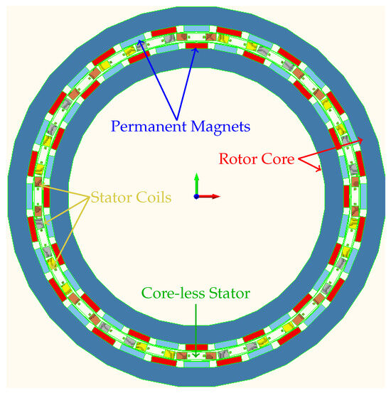
Figure 1.
FEA model of the C-GEN generator.
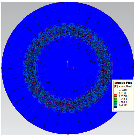
Figure 2.
Magnetic field distribution in the C-GEN generator.

Table 1.
Generator properties [17].
Table 2.
FEA verification [17].
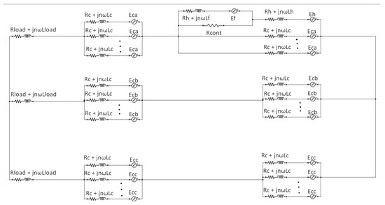
Figure 3.
Three-Phase equivalent circuit of C-GEN under ITSC [17].
3. Mathematical Modeling
3.1. Analysis of C-Gen Under Impedance Imbalance
The equivalent circuit of the single phase under investigation is shown in Figure 4. The analysis is performed under steady-state conditions, which is consistent with the simulations. represents the electromotive force (EMF) of each coil, represents the impedance of each coil, where denote the resistance and self-inductance of each coil, respectively, and k denotes the number of parallel-connected coils, which in our case is four.
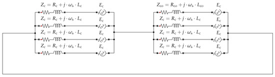
Figure 4.
Single-phase equivalent for coil asymmetries.
The mutual inductance is neglected, as the very low operating frequency and the absence of a stator core significantly limit its impact. In Equations (1)–(3), the currents corresponding to the phase, the imbalanced coil, and the parallel-connected coil are obtained by the mesh analysis.
represents the impedance of the asymmetric coil, while the EMF of that coil is assumed to remain unchanged. The current of the imbalanced coil, as presented in Equation (2), will vary inversely with the impedance. To be more specific, as the asymmetric impedance increases, the current decreases, and vice versa. For the current of the phase and the parallel-connected coils, a derivative with respect to the asymmetric impedance is implemented in Equations (4) and (5).
The derivative of the phase current is negative, meaning that the rise of the coil impedance will lead to the decrement of the phase current, whereas the derivative of the parallel-connected coils is greater than zero, and, therefore, as the impedance increases, the current of these coils will also increase.
Therefore, circulating currents will flow through the parallel-connected coils that cannot be observed by the total phase current. The ITSCs will also induce circulating currents, as has been investigated in [17] and in Equations (6)–(11), where . stands as the contact resistance of the ITSC and is the short circuit ratio. Previous research has shown that the phase current increases as the contact resistance decreases, since the derivative in Equation (6) is >0, and decreases as the number of shorted turns increases, as indicated by the derivative in Equation (9) being <0. The current of the imbalanced coil decreases as the contact resistance decreases and as the number of shorted turns increases, as reflected by the derivatives in Equations (7) and (10) being >0 and <0, respectively. Finally, the current of the parallel-connected coil increases as the contact resistance decreases and as the number of shorted turns increases, as shown by the derivatives in Equations (8) and (11) being <0 and >0 respectively.
In summary, the phase current—which is the quantity that can be measured in practical applications—is affected in a similar manner in both faulty scenarios.
Simulation Results
The simulations that have been performed are for two load conditions: and of the nominal load. Impedance asymmetry has been modeled by increasing the resistance and inductance of the affected coil by , , and of its nominal value. As shown in Figure 5 and Figure 6, the current of the affected coil demonstrates that the mathematical modeling that has been conducted in the previous section agrees with the simulation results. Regarding the current in the parallel-connected coil, which is shown in Figure 7 and Figure 8, it can be observed that it agrees with Equation (5), as it increases with respect to the imbalance level. While its deviation is smaller than that of the imbalanced coil, it still remains noticeable. Additionally, regarding the phase current that is illustrated in Figure 9, it can be observed that it aligns with Equation (4), as the deviation is negligible. Finally, the evolution of the current is not linearly proportional to the severity of the fault. For example, the current of the asymmetric coil given in Equation (2) can be rewritten as Equation (12), where u denotes the percentage of coil asymmetry. The decrease in current therefore depends on both the load and the coil impedance. For this reason, the cases of a short circuit () and of a very small coil impedance are considered. These cases provide the range of possible current reduction percentages. The simulation results are presented in Table 3, where the increase in the current of the parallel-connected coil remains within the estimated range, while the reduction in the current of the imbalanced coil is slightly lower than expected. Moreover, the influence of the load is evident, as the deviation in the currents of both the imbalanced and the parallel-connected coils becomes more pronounced.
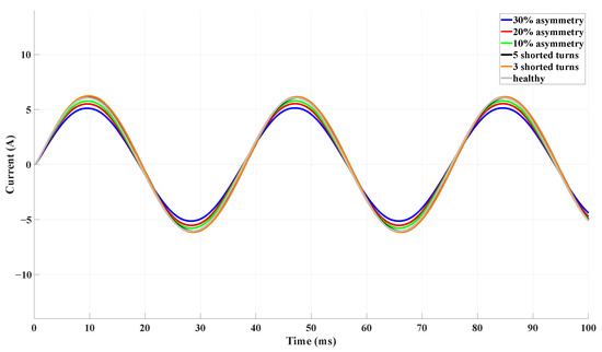
Figure 5.
Current in the asymmetrical coil as a function of time.
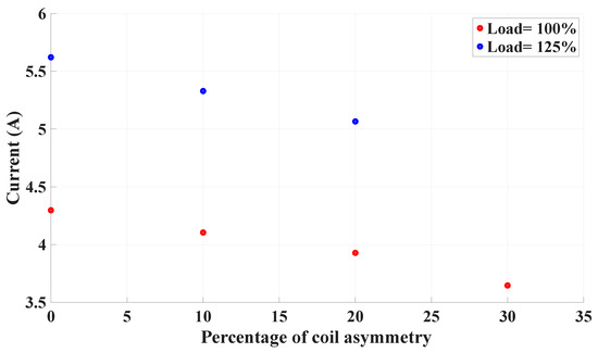
Figure 6.
Current in the asymmetrical coil as a function of the severity of the coil asymmetry.
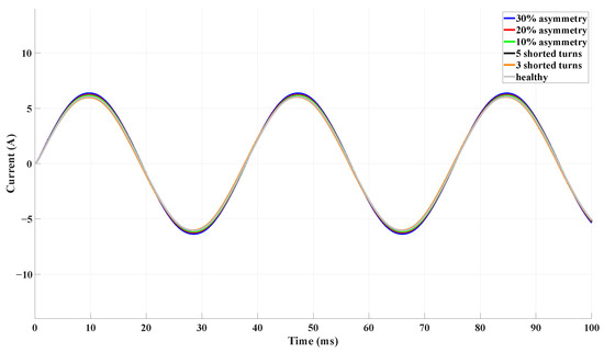
Figure 7.
Current from the parallel-connected coil to the imbalanced coil as a function of time.
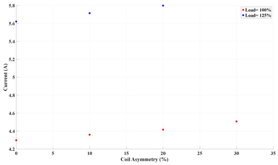
Figure 8.
Current from the parallel coils to the asymmetrical coil as a function of the coil asymmetry.
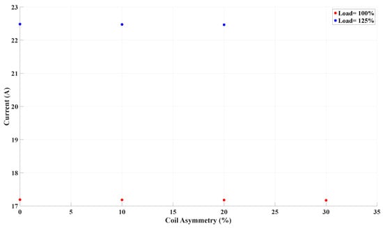
Figure 9.
Current of the phase as a function of the severity of the coil asymmetry.
Table 3.
Current of the phase, asymmetric coil, and parallel connected coils.
For the ITSC case, Table 4 shows that, as the contact resistance decreases and the number of shorted turns increases, both the phase current and the current of the healthy part of the shorted coil decrease, while the current of the parallel-connected coil increases.
Table 4.
Current of the phase, healthy part of shorted coil, and parallel connected coils.
4. Diagnostic Techniques
4.1. Negative-Sequence Current
The negative-sequence component of the stator current (NSC) under healthy operation will be zero. In cases of both coil asymmetry and ITSC, three-phase imbalance causes the NSC amplitude to increase; therefore, the NSC amplitude by itself cannot distinguish between these two faults, as can be seen in Table 5. To explore the capability of the NSC in detecting these faults, the phase shift in the phase current caused by coil asymmetry and ITSC is examined. The healthy phase current is given in Equation (14), where represents the angle of the EMF, while Equations (15)–(17) showcase the phase-current angles for the healthy, coil asymmetry, and ITSC conditions. In this study, the coil asymmetry has been achieved with the increase in the impedance of one stator coil by a percentage. It can be seen that the angle depends on the generator and load parameters, and therefore the evolution of the current angle will also depend on the parameters of the machine.
Table 5.
Negative-current sequence.
The NSC can be calculated using Equation (18), where , , represents the positive sequence current, and stands as the imbalance in the phase current. According to Equations (16) and (17), each fault causes the phase current to shift by a different angle. This phase shift is reflected in Equation (18), and therefore the phase shift monitoring of the NSC can be used for distinguishing these two faults. This phase shift is illustrated in Figure 10, where it can be observed that that the coil asymmetry fault has a different phase angle compared to the ITSC fault. Although the present work is simulation-based, the milliamp-level NSC observed in Figure 11 and Table 5 is compatible with the noise performance of commercially available closed-loop current sensors. For example, sensors such as the LEM IT-65-S specify a primary-referred RMS noise of approximately 45 μA, yielding single-cycle SNRs of 27–50 dB for NSC in the 1–15 mA range. Since the proposed method relies on the synchronous extraction of the NSC phase rather than instantaneous magnitude, coherent averaging and narrowband demodulation substantially suppress broadband noise and switching ripple. Under these conditions, phase-angle tracking remains a robust diagnostic feature, even for small NSC amplitudes.
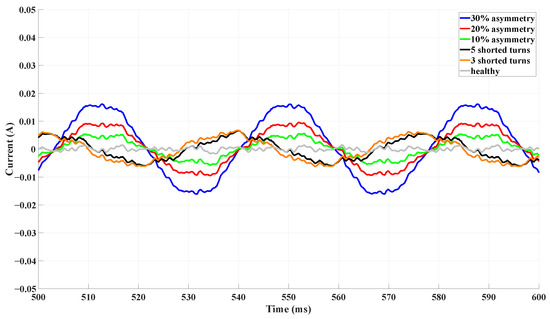
Figure 10.
Negative-sequence current as a function of time.
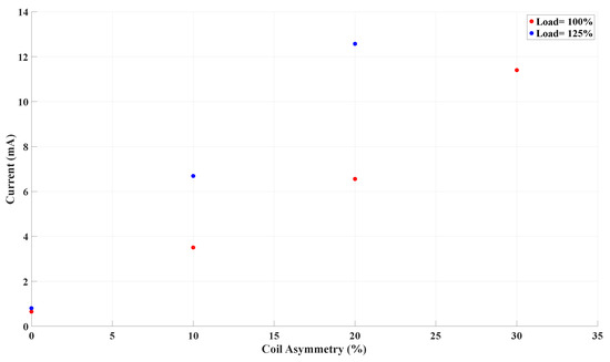
Figure 11.
Negative-sequence current as a function of the severity of the coil asymmetry.
4.2. Torque Analysis
Figure 12 plots the electromagnetic torque at steady state under healthy and faulty conditions. All cases settle near the nominal torque level of 1600 Nm, but the coil-asymmetry cases produce slightly different average torques. The torque waveforms for the faulty cases also show a minor oscillatory ripple superimposed on the mean value, while the healthy torque is smoother. This suggests the asymmetries induce more torque pulsation.
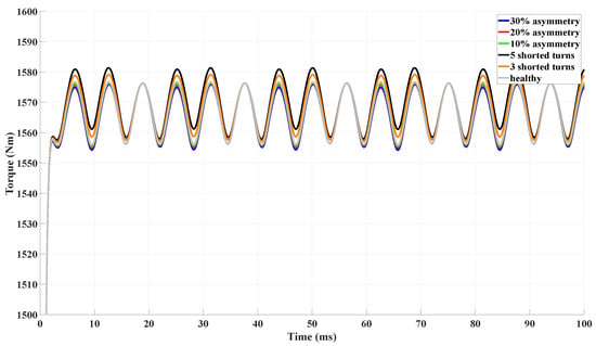
Figure 12.
Torque as a function of time.
The harmonic content of the torque is shown in Figure 13 and Table 6. Under healthy conditions, only the expected harmonics are present at low levels. However, the torque spectrum of the coil asymmetry cases shows a dominant 2nd-order component. Figure 14 quantifies this effect: a monotonic increase in the 2nd-harmonic torque amplitude with increasing coil imbalance is observed. At 30% asymmetry, the 2nd-order harmonic is roughly 30 dB above the balanced machine. In the case of the ITSC, the 2nd increases similarly to that observed in coil asymmetries, as shown in Figure 15. The core-less stator design of the C-GEN eliminates magnetic saturation, which in turn removes the induced harmonics in both the magnetic flux and the stator current. In addition, the air-cored stator has low permeance, resulting in a very small mutual inductance that further limits harmonic induction in the magnetic flux. The 4th harmonic is the result from the interaction between the 1st harmonic of the rotor and the 3rd harmonic of the stator, as well as between the 1st harmonic of the stator and the 3rd harmonic of the rotor, due to the negligible 3rd harmonic of the stator coil, as shown in Figure 16. Therefore, the 4th harmonic of the torque does not increase even in the presence of coil asymmetry.
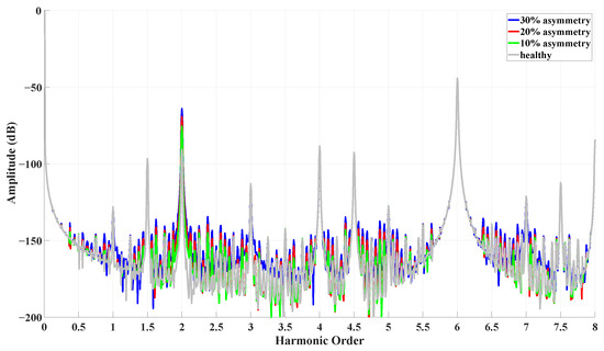
Figure 13.
Torque signature analysis for coil asymmetries.
Table 6.
Torque spectra amplitude.
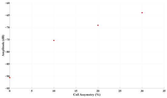
Figure 14.
Torque signature of 2nd harmonic for coil asymmetries.
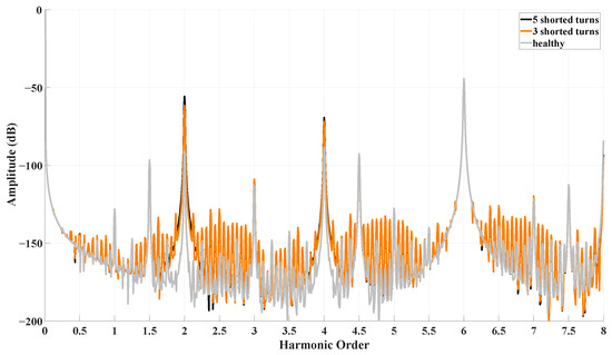
Figure 15.
Torque signature analysis for ITSCs.
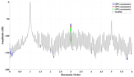
Figure 16.
Third-order harmonic of the asymmetric coil.
In contrast, under an ITSC condition, the shorted coil operates as a transformer. The air-gap magnetic flux induces an EMF in the shorted coil in accordance with Faraday’s law, which in turn generates a circulating current. This current inherits the 3rd harmonic of the rotor field and, acting again through transformer action, induces the same 3rd-harmonic component in the remaining part of the stator coil, as validated in Figure 17. Consequently, due to the interaction between the 1st harmonic of the rotor and the 3rd harmonic of the stator, the 4th harmonic of the electromagnetic torque is expected to increase under ITSC conditions.
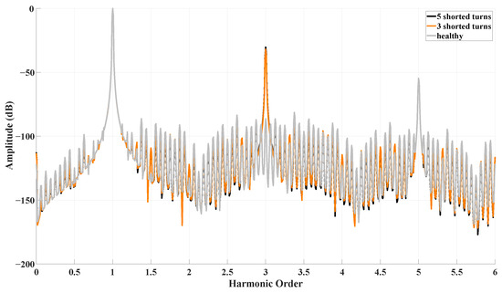
Figure 17.
Third-order harmonic of the shorted coil current.
Table 6 shows that, under similar faulty conditions, the torque harmonics remain unchanged as the load increases. This behavior can be attributed to the core-less stator design of the C-GEN, which eliminates magnetic saturation, as well as to the ideal conditions assumed in the FEA. As a result, even with increasing current, the amplitudes of the torque harmonics remain constant.
In the FEA, given the low harmonic content of this generator, an increase of at least 20 dB in the 2nd and 4th harmonics is expected for the ITSC to be detectable at this scale. However, experimental results are essential to properly establish quantitative thresholds. Ultimately, the threshold should be defined using a combination of both the 2nd and 4th harmonics to enhance the effectiveness of this method.
5. Conclusions & Future Work
This study investigated the identification of coil asymmetry and ITSC faults in a low-speed, air-cored PMSG with parallel-connected stator coils. The modeling included both mathematical analysis and simulation to enable fault detection. An intriguing finding is the impact of the circulating current flowing through the parallel-connected coils, which cannot be observed through phase current measurements. This phenomenon highlights the importance of diagnosing these faults, as the most affected components are not visible. In this research, two diagnostic techniques were implemented: the negative-sequence current (NSC) and the torque monitoring. The NSC has the potential to identify the coil asymmetry from the ITSC by monitoring the phase angle of this current, although the small amplitude of the signals highlights the necessity for experimental results. Torque monitoring also demonstrated potential for identifying these faults in the C-Gen due to the generator’s geometry by observing the 4th-order harmonic. Although the increase in this harmonic in the ITSC is generally small, its presence, combined with the use of additional techniques, could enable the distinction between ITSC and coil asymmetry. Overall, the key contribution of this study is the proposal and validation of a dual diagnostic approach—based on NSC phase-angle tracking and torque harmonic analysis—that allows ITSC and coil asymmetry to be distinguished in a parallel-connected, core-less PMSG, even though they generate nearly identical three-phase current signatures.
As future work, experimental validation is essential to validate these findings and to further assess the potential of NSC and torque monitoring. Additionally, this work proposes the development of a control system capable of distinguishing coil asymmetries from ITSCs in real time, which will be programmed to take corrective actions with the aim of minimizing damage in the event of a fault. Finally, combining ITSC and coil asymmetry with other static faults, such as static eccentricity and open-circuit faults, should be investigated to achieve more reliable fault detection.
Author Contributions
Conceptualization, N.G. and M.M.; Methodology, N.G. and A.S.; Software, N.G., A.S. and M.S.; Validation, M.S.; Formal analysis, K.N.G.; Investigation, N.G., A.S., M.S. and K.N.G.; Resources, M.S. and M.M.; Writing – original draft, N.G., A.S. and K.N.G.; Visualization, M.S.; Supervision, M.M. and K.N.G.; Project administration, M.M.; Funding acquisition, M.M. and K.N.G. All authors have read and agreed to the published version of the manuscript.
Funding
This work has been supported by the EU HORIZON and UKRI project entitled “MEGA PTO WAVE”, EU HORIZON project ID: 101147321 https://www.megawave-pto.eu/ (accessed on 28 October 2025).
Data Availability Statement
The original contributions presented in this study are included in the article. Further inquiries can be directed to the corresponding author.
Conflicts of Interest
The authors declare no conflicts of interest.
References
- von Jouanne, A.; Agamloh, E.; Yokochi, A. A Review of Offshore Renewable Energy for Advancing the Clean Energy Transition. Energies 2025, 18, 4798. [Google Scholar] [CrossRef]
- Keysan, M.; Mueller, A.; McDonald, N.; Hodgins, N.; Shek, J. Designing the C-GEN Lightweight Direct Drive Generator for Wave and Tidal Energy. IET Renew. Power Gener. 2012, 6, 161–170. [Google Scholar] [CrossRef]
- Riera-Guasp, M.; Antonino-Daviu, J.A.; Capolino, G.-A. Advances in Electrical Machine, Power Electronic, and Drive Condition Monitoring and Fault Detection: State of the Art. IEEE Trans. Ind. Electron. 2015, 62, 1746–1759. [Google Scholar] [CrossRef]
- Sergakis, A.; Salinas, M.; Gkiolekas, N.; Gyftakis, K.N. A Review of Condition Monitoring of Permanent Magnet Synchronous Machines: Techniques, Challenges and Future Directions. Energies 2025, 18, 1177. [Google Scholar] [CrossRef]
- Li, H.; Zhu, Z.-Q.; Azar, Z.; Clark, R.; Wu, Z. Fault Detection of Permanent Magnet Synchronous Machines: An Overview. Energies 2025, 18, 534. [Google Scholar] [CrossRef]
- Pérez, R.; Cros, J.; Picard, M. Real-Time Modeling of Static, Dynamic and Mixed Eccentricity in Permanent Magnet Synchronous Machines. Machines 2025, 13, 120. [Google Scholar] [CrossRef]
- Rengifo, J.; Moreira, J.; Vaca-Urbano, F.; Alvarez-Alvarado, M.S. Detection of Inter-Turn Short Circuits in Induction Motors Using the Current Space Vector and Machine Learning Classifiers. Energies 2024, 17, 2241. [Google Scholar] [CrossRef]
- Cao, L.; Wu, Z. On-Line Detection of Demagnetization for Permanent Magnet Synchronous Motor via Flux Observer. Machines 2022, 10, 354. [Google Scholar] [CrossRef]
- Akbar, S.; Vaimann, T.; Asad, B.; Kallaste, A.; Sardar, M.U.; Kudelina, K. State-of-the-Art Techniques for Fault Diagnosis in Electrical Machines: Advancements and Future Directions. Energies 2023, 16, 6345. [Google Scholar] [CrossRef]
- Zsuga, Á; Dineva, A. Early Detection of ITSC Faults in PMSMs Using Transformer Model and Transient Time-Frequency Features. Energies 2025, 18, 4048. [Google Scholar] [CrossRef]
- Huang, C.; Zhou, L.; Cao, Z.; Yao, G. Fault-Tolerant Control Strategy with Asymmetric Phase Currents for Single to Four-Phase Open-Circuit Faults of Six-Phase PMSM. Energies 2021, 14, 3163. [Google Scholar] [CrossRef]
- Carrillo-Rios, J.; Aciego, J.J.; Gonzalez-Prieto, A.; Gonzalez-Prieto, I.; Duran, M.J.; Lara-Lopez, R. Remaining Secondary Voltage Mitigation in Multivector Model Predictive Control Schemes for Multiphase Electric Drives. Machines 2025, 13, 862. [Google Scholar] [CrossRef]
- Li, W.; Song, P.; Li, Q.; Li, Z.; Kar, N.C. Open-Phase Fault Modeling for Dual Three-Phase PMSM Using Vector Space Decomposition and Negative Sequence Components. IEEE Trans. Magn. 2022, 58, 8204106. [Google Scholar] [CrossRef]
- Górny, K.; Kuwałek, P.; Pietrowski, W. Increasing Electric Vehicles Reliability by Non-Invasive Diagnosis of Motor Winding Faults. Energies 2021, 14, 2510. [Google Scholar] [CrossRef]
- El Sayed, W.; Abd El Geliel, M.; Lotfy, A. Fault Diagnosis of PMSG Stator Inter-Turn Fault Using Extended Kalman Filter and Unscented Kalman Filter. Energies 2020, 13, 2972. [Google Scholar] [CrossRef]
- Wei, D.; Liu, K.; Hu, W.; Peng, X.; Chen, Y.; Ding, R. Short-Time Adaline Based Fault Feature Extraction for Inter-Turn Short Circuit Diagnosis of PMSM via Residual Insulation Monitoring. IEEE Trans. Ind. Electron. 2023, 70, 3103–3114. [Google Scholar] [CrossRef]
- Gkiolekas, N.; Sergakis, A.; Mueller, M.; Gyftakis, K.N. Analysis and Diagnosis of ITSC in Dual Rotor Air-Cored PMSG-Parallel Connected Stator Coils. In Proceedings of the 2025 IEEE Symposium on Diagnostics for Electric Machines, Power Electronics and Drives (SDEMPED), Dallas, TX, USA, 24–27 August 2025; pp. 1–7. [Google Scholar] [CrossRef]
- Drif, M.; Drif, M.; Estima, J.O.; Cardoso, A.J.M. The use of the stator instantaneous complex apparent impedance signature analysis for discriminating stator winding faults and supply voltage unbalance in three-phase induction motors. In Proceedings of the 2013 IEEE Energy Conversion Congress and Exposition, Denver, CO, USA, 15–19 September 2013; pp. 4403–4411. [Google Scholar] [CrossRef]
- Gyftakis, K.N.; Kappatou, J.C. The Zero-Sequence Current as a Generalized Diagnostic Mean in Δ-Connected Three-Phase Induction Motors. IEEE Trans. Energy Convers. 2014, 29, 138–148. [Google Scholar] [CrossRef]
- Zhu, L.; Wu, L.; Liu, J.; Guo, Y. Negative Sequence Current Suppression of Dual Three-Phase Permanent Magnet Synchronous Machines Considering Inductance Asymmetry. In Proceedings of the 2019 22nd International Conference on Electrical Machines and Systems (ICEMS), Harbin, China, 11–14 August 2019; pp. 1–6. [Google Scholar] [CrossRef]
- Duda, A.; Sułowicz, M. A New Effective Method of Induction Machine Condition Assessment Based on Zero-Sequence Voltage (ZSV) Symptoms. Energies 2020, 13, 3544. [Google Scholar] [CrossRef]
- Oliveira, L.M.R.; Cardoso, A.J.M. Comparing power transformer turn-to-turn faults protection methods: Negative sequence component versus space vector algorithms. In Proceedings of the 2015 IEEE 10th International Symposium on Diagnostics for Electrical Machines, Power Electronics and Drives (SDEMPED), Guarda, Portugal, 1–4 September 2015; pp. 289–295. [Google Scholar] [CrossRef]
- Xie, F.; Jiang, M.; Lu, T.; Hu, F.; Huang, Y.; Ma, C.; Song, W. Comparative Study of Negative Sequence Current-based and Current Residual-based Online Diagnosis Method for Inter-turn Faults in PMSM Drives. In Proceedings of the 2024 5th International Conference on Power Engineering (ICPE), Shanghai, China, 13–15 December 2024; pp. 166–171. [Google Scholar] [CrossRef]
- Forstner, G.; Kugi, A.; Kemmetmüller, W. Fault-tolerant torque control of a three-phase permanent magnet synchronous motor with inter-turn winding short circuit. Control Eng. Pract. 2021, 113, 104846. [Google Scholar] [CrossRef]
- Ahsanullah, K.; Panda, S.K.; Shanmukha, R.; Nadarajan, S. Inter-turns fault diagnosis for surface permanent magnet based marine propulsion motors. In Proceedings of the 2016 IEEE 2nd Annual Southern Power Electronics Conference (SPEC), Auckland, New Zealand, 5–8 December 2016; pp. 1–6. [Google Scholar] [CrossRef]


Disclaimer/Publisher’s Note: The statements, opinions and data contained in all publications are solely those of the individual author(s) and contributor(s) and not of MDPI and/or the editor(s). MDPI and/or the editor(s) disclaim responsibility for any injury to people or property resulting from any ideas, methods, instructions or products referred to in the content. |
© 2025 by the authors. Licensee MDPI, Basel, Switzerland. This article is an open access article distributed under the terms and conditions of the Creative Commons Attribution (CC BY) license.