Article

Numerical and Experimental Study of a Bio-Inspired Flapping Wing with Increasing Twist Angle Along the Wingspan


1
College of Engineering, Ocean University of China, Qingdao 266100, China
2
The State Key Laboratory of Costal and Offshore Engineering, Ocean University of China, Qingdao 266100, China
*
Author to whom correspondence should be addressed.
Machines 2026, 14(1), 102; https://doi.org/10.3390/machines14010102
Submission received: 21 December 2025 / Revised: 12 January 2026 / Accepted: 13 January 2026 / Published: 16 January 2026
(This article belongs to the Section Robotics, Mechatronics and Intelligent Machines)

Abstract

Inspired by the movements of sea turtle forelimbs, this study presents a bio-inspired underwater flapping wing with three degrees of freedom. This flapping wing mechanism can more accurately simulate the rotational motion of a sea turtle’s forelimbs to generate greater propulsive force. The highlight is the gear transmission mechanism arranged along the wingspan, enabling a preset increasing twist angle along the wingspan. Computational fluid dynamics simulations are conducted to evaluate the hydrodynamic performance of the proposed flapping wing system. The effects of different spanwise twist angles along the wingspan on thrust generation are quantitatively analyzed, as well as the influence of key kinematic parameters, including the longitudinal flapping angle, spanwise increasing twist angle, and elevation angle. The results indicate that, compared with a uniform twist angle, the spanwise increasing twist significantly increases the peak thrust during specific phases of the flapping cycle. It is further revealed by flow field analyses that the formation of vortices near the trailing edge enhances the propulsive force in the streamwise direction. To further validate the proposed concept, a prototype of the mechanism is fabricated and experimentally tested under low-frequency actuation, confirming the feasibility of the mechanical design. Overall, these results demonstrate the potential of the proposed approach for bio-inspired underwater propulsion and provide useful guidance for future flapping wing mechanisms and kinematic design.

1. Introduction

Research on bio-inspired underwater robots aims to overcome the limitations of conventional underwater systems in propulsion efficiency, maneuverability, and environmental adaptability by emulating the locomotion strategies of aquatic organisms. Various methods have been explored, such as the development of variable-stiffness mechanisms [1,2], modeling of bionic motion [3], and the study of locomotion patterns [4,5]. These approaches provide promising directions for enhancing the performance of underwater robotic systems.
As early as the 20th century, Lighthill proposed rigorous mathematical and fluid dynamics theories explaining how organisms generate propulsive forces through body deformation in fluid environments [6]. So far, various new propulsion schemes have been developed, aimed at exploring underwater propulsion efficiency through flexible deformation [7,8], multi-stable actuation [9,10], and other mechanisms. Among these, research on caudal fin propulsion is the most advanced [11,12,13], but it still faces challenges in posture stability and control efficiency. To address these issues, some scholars have proposed a multi-fin cooperative propulsion scheme [14]. This scheme not only helps reduce heading deviation but also supports amphibious walking [15]. Meanwhile, pectoral-fin and undulatory fin [16,17] also demonstrate excellent thrust performance, often enabling multiple degree-of-freedom (DOF) coordination [18] and complex movements such as pitch and roll [19,20]. Currently, integrated design frameworks that combine mechanism development with hydrodynamic simulation have become a prevalent strategy for investigating propulsion performance from the perspectives of vortex dynamics and pressure distribution [21,22,23].
However, in terms of environmental adaptability, energy efficiency, and maneuverability, flapping propulsion exhibited by sea turtles and penguins has been increasingly recognized in recent years as a promising approach for underwater locomotion. This flapping mechanism not only demonstrates the ability to harvest energy from small-scale waves [24] but also exhibits the potential for high-speed propulsion in water [25,26,27,28,29]. Fan et al. indicate that flapping wing folding and torsional deformation can substantially increase the time-averaged thrust under specific operating conditions [30]. Harada et al. quantitatively evaluated the influence of flapping wing bending deformation on propulsion efficiency and reported a 1.8-fold improvement by reducing the angle of attack during the upstroke phase [31]. Chu et al. focused on sea turtles and derived two-DOF flapping wing motion equations using image processing techniques [32]. Yan et al. proposed a flapping wing model with variable stiffness and used numerical simulations to analyze the effects of stiffness variation on propulsion performance [33]. Chu et al. developed an underactuated bio-inspired propulsion system based on sea turtle flapping fins [34]. Li et al. developed a multi-DOF sea turtle robot capable of executing forward motion, turning, and other maneuvers [35]. Van et al. conducted a systematic study of bionic flapping thrusters, involving 3D motion capture of sea turtles, programming their locomotion patterns, and developing a bionic robot achieving a swimming speed of 0.6 m/s [36,37,38]. However, existing multi-DOF flapping torsion methods cannot fully replicate biological motion, nor do they enable a continuous distribution of spanwise increasing twist angle of the flapping structure. As a result, active flapping deformation cannot be fully exploited to improve propulsion efficiency. Although studies have shown that body flexibility deformation plays an important role in caudal fin propulsion [39,40,41], its application in flapping-wing systems has received little attention.
Therefore, this study employs computational fluid dynamics and experimental methods to develop and evaluate a biomimetic underwater flapping wing system with an increasing twist angle along the wingspan. The main contributions of this paper are as follows: (1) a bio-inspired flapping wing mechanism with an spanwise increasing twist angle is developed to more realistically reproduce natural flapping motion; (2) computational fluid dynamics simulations are conducted to analyze the hydrodynamic characteristics of the proposed underwater flapping wing model; and (3) a comparative study is performed to evaluate the advantages and limitations of several flapping motion schemes in terms of thrust performance and flow characteristics.

2. Motion and Mechanisms Design

2.1. Biomimetic Inspiration and Motion Modeling

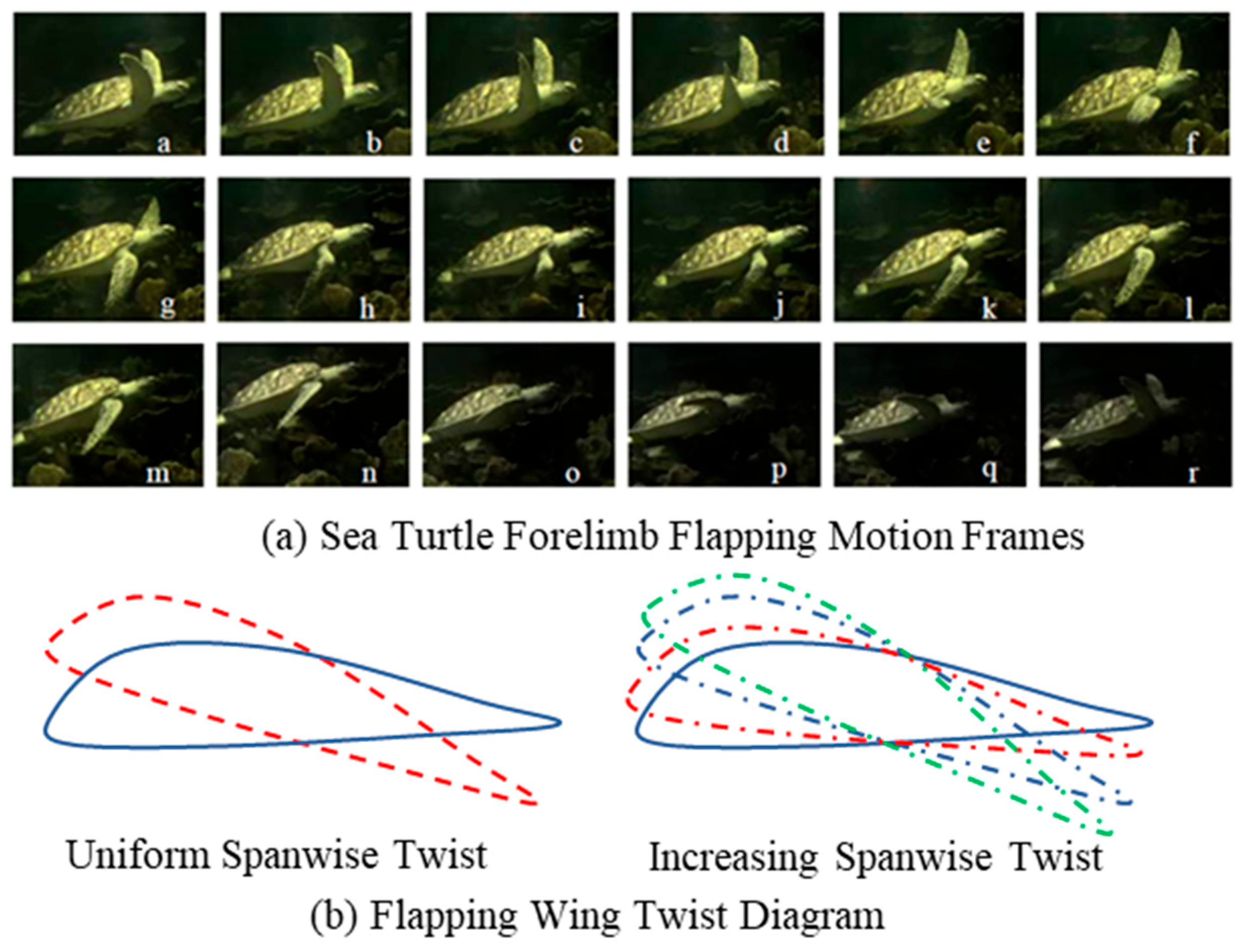
Conventional multi-DOF flapping wing systems typically assume uniform twist angles along the wingspan. However, this simplification differs from the kinematics observed in biological swimmers. A gradual torsional deformation of the hydrofoil during propulsion can be observed from analyses of sea turtle motion. As shown in Figure 1, the twist angle increases gradually from the wing root to the tip, forming a continuous distribution of increasing twist angle along the wingspan. This structure can achieve vortex dynamic regulation during swimming, enhancing hydrodynamic efficiency.
To reproduce this swimming pattern, a motion model with position-dependent torsion is established in this study. The motion of an arbitrary point P0 = [x0, y0, z0] on the flapping wing is described by successive time-dependent rotations about the Z, X, and Y axes:
P t = R Y θ t R X ϕ t R Z ψ t P 0
where the rotation angles are defined as follows:
θ t = a 2 sin ω t + θ i ϕ t = a 3 sin ω t + ϕ i ψ t , z = a 1 sin ω t + ψ i z z max
The rotation matrices Rz, Rx, and Ry are
R Z ψ = cos ψ sin ψ 0 sin ψ cos ψ 0 0 0 1 R X ϕ = 1 0 0 0 cos ϕ sin ϕ 0 sin ϕ cos ϕ R Y θ = cos θ 0 sin θ 0 1 0 sin θ 0 cos θ
The increasing twist angle along the wingspan, denoted as ψ(t, z), varies with the spatial coordinate z. This distribution mimics the biological twist characteristics of sea turtle forelimbs. This formulation allows the flapping mechanism to achieve continuous three-dimensional kinematics, including position-dependent twist that is essential for biomimetic propulsion.

2.2. Mechanical Design of the 3-DOF Limb

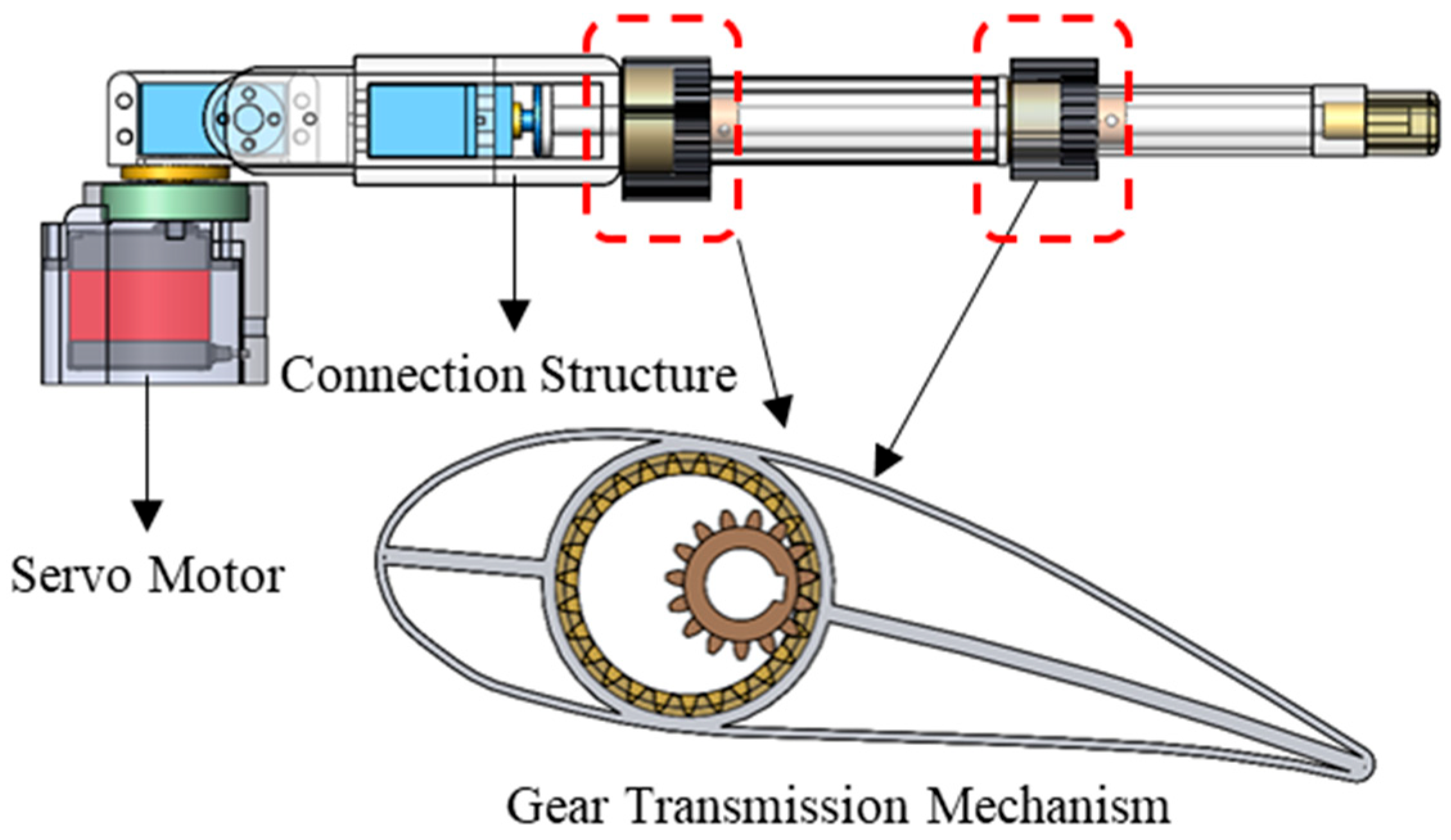
To realize the proposed functionality, a three-DOF flapping wing mechanism is designed, as shown in Figure 2. Unlike conventional bionic sea turtle robots, the sea turtle flapping wing is equipped with multiple sets of supporting wings, each connected to the drive shaft via a gear mechanism with a different transmission ratio. This method enables gradient torsional deformation along the wingspan direction.
The twist angle at the i-th segment is expressed as follows:
ψ 1 i t = R i ψ i n t
where Ri denotes the gear ratio of segment i, and ψin(t) is the input rotation angle.
To maintain structural continuity and prevent mechanical interference, gear ratios are designed to satisfy the following:
R 1 < R 2 < R 3
This ensures the twist angle increases gradually from the root to the tip, replicating the biological twist pattern observed in sea turtles.
The bio-inspired flapping mechanism has three DOF: a shoulder pitch joint for longitudinal flapping, an elevation joint for elevation motion, and the spanwise increasing twist angle. Along the wingspan. These joints are arranged in a linear sequence and mounted on a rigid base frame to ensure coordinated motion. The pitch joint is driven by the first servomotor with a horizontal axis, while the elevation joint is actuated by the second servomotor through a vertical linkage system. Spanwise twist motion is achieved through a series of gear sets distributed along the wingspan.
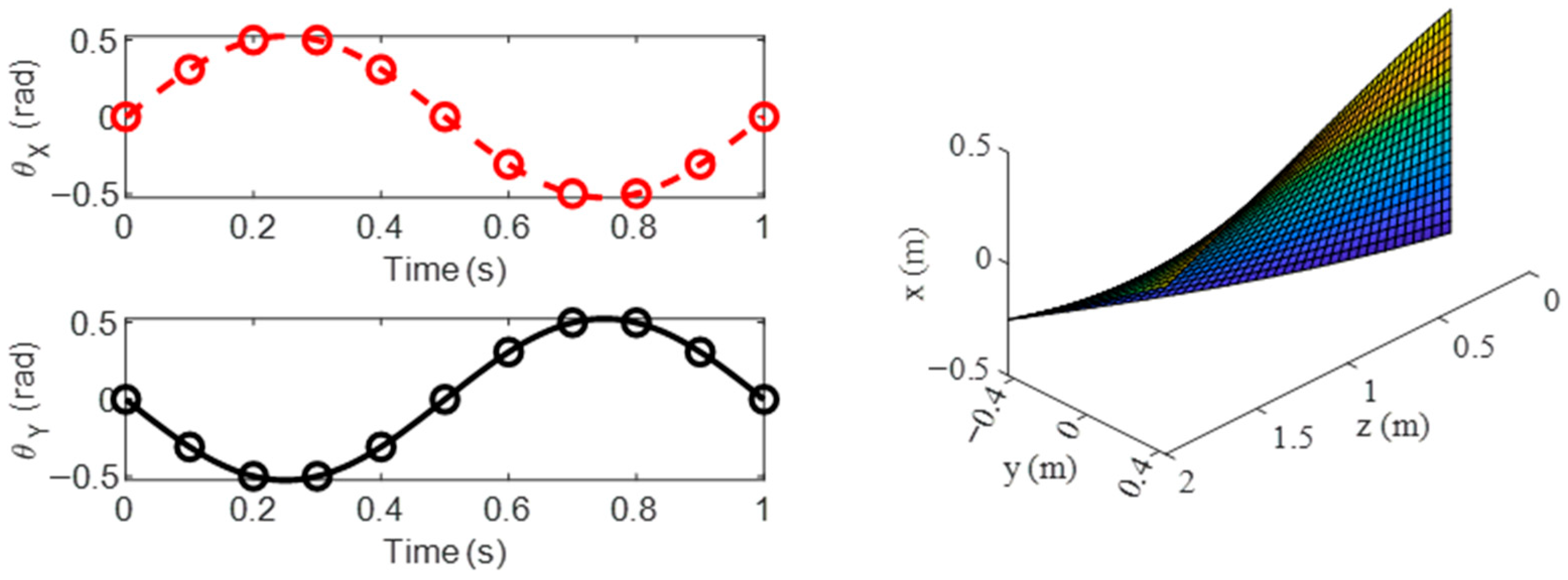
To verify the correctness of the proposed bio-inspired motion model, the kinematic behavior of each DOF is examined. As shown in Figure 3, the three degrees of freedom, namely longitudinal flapping, elevation motion, and spanwise torsion, are defined according to Equation (2).
In addition, flexible silicone skin is manufactured and bonded to ensure continuous deformation of the flapping wing surface. The silicone skin is fabricated through a molding process. First, two-part liquid silicone is mixed and vacuum degassed to remove entrapped air bubbles. The degassed silicone is then poured into a three-dimensionally printed PLA mold that defines the external geometry of the flapping wing. After curing at room temperature, the silicone skin is demolded and trimmed to the desired shape. The finished skin is subsequently bonded and sealed to the rigid wing skeleton using a waterproof structural adhesive. This skin skeleton design provides localized passive compliance under flow-induced loading while maintaining the overall kinematic accuracy of the flapping wing.

3. Results

3.1. Numerical Parameter Setting

To evaluate the hydrodynamic performance of the bionic flapping wing system, computational fluid dynamics simulations are conducted. The hydrodynamic forces acting on a flapping wing arise from unsteady flow generated by periodic oscillatory motion. To model this flow, the incompressible Navier–Stokes equations are employed to describe the fluid dynamics associated with the three-DOF flapping kinematics:
u t + u u = 1 ρ ρ + v 2 u u = 0
where u denotes the velocity field, p is the pressure field, ρ is the fluid density, and ν is the kinematic viscosity. Due to the complex geometry and motion of the flapping wing, analytical solutions are difficult to obtain. Therefore, numerical simulations based on the finite volume method are employed. In this study, the governing equations are solved using ANSYS Fluent 2022R1.
Time-dependent hydrodynamic forces on the flapping wing are computed by integrating pressure and viscous stresses over the body surface:
F = S p n + μ u + u T n d S
where n is the outward unit normal, μ = ρν is the dynamic viscosity, and S is the wing surface.
The numerical simulations are conducted by prescribing a regular flapping motion of the turtle forelimb in initially quiescent water. Since no steady inflow velocity is imposed, the flow field is entirely induced by the prescribed kinematics. Therefore, the Reynolds number is not defined based on a steady swimming velocity, but instead on a characteristic motion-induced velocity. The Reynolds number is defined as follows:
Re = U c v
where U denotes the wing-tip velocity, c is the representative length of the flapping wing, and v is the kinematic viscosity of water. Due to variations in the flapping speed across different test cases, the resulting Reynolds numbers are not entirely identical. In the simulations conducted in this paper, the Reynolds number ranges from 0.55 × 10⁵ to 2 × 10⁵, which is broadly comparable to the Reynolds number employed in Reference [43].
Additionally, the Strouhal number is calculated to be 0.23 and defined as follows:
S t = f A U
where f is the flapping frequency, and A is the peak-to-peak wing-tip excursion. The value of the Strouhal number puts sea turtles into a range of 0.2 to 0.4, as found in other swimming and flying animals tuned for high power efficiency.
In the Fluent simulation setup, the SST k–ω turbulence model is employed. This model combines the advantages of the k–ω formulation in the near-wall region with the robustness of the k–ε model in the outer flow through a blending function, allowing for accurate prediction of flows with strong adverse pressure gradients, unsteady separation, and moving boundaries, which are characteristic of flapping-wing propulsion. In addition, dynamic meshing is implemented using a user-defined function, updating mesh deformations induced by flapping motion through dynamic layering and local remeshing.
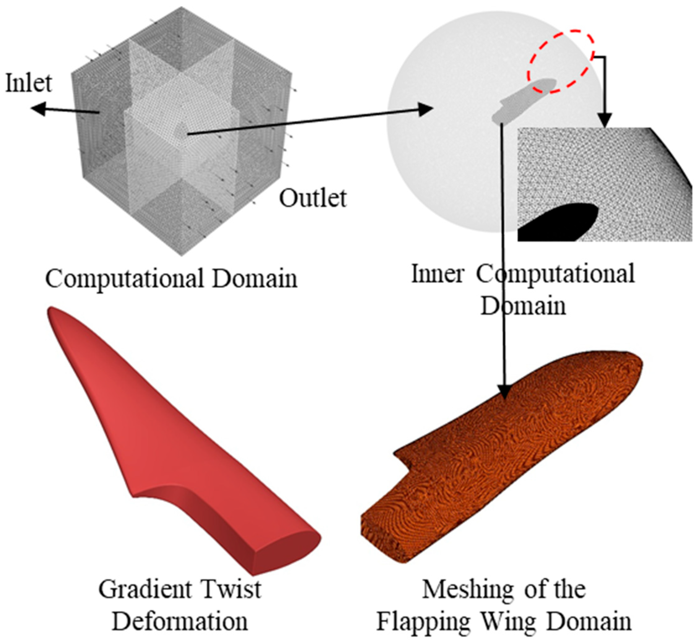
In addition, a pressure-based solver is used for incompressible flow simulations. Unsteady calculations are enabled with a time step of T/1000. The inlet boundary is specified as a velocity inlet with a free-stream velocity of 0 m/s, while the outlet boundary is treated using the default solver settings. Second-order upwind schemes are used to discretize convective terms, and central difference schemes are applied to diffusive terms to ensure accurate gradient evaluation. Pressure velocity coupling is handled using the COUPLED algorithm. The mesh of the flapping wing model and the locally densified regions are shown in Figure 4.
The computational domain is discretized using an unstructured tetrahedral mesh. To accommodate the large-amplitude flapping motion and avoid the formation of negative cell volumes during dynamic mesh deformation, a locally refined circular region is introduced around the flapping wing. This refinement is applied to regions experiencing large deformation gradients, thereby enhancing mesh robustness while controlling the overall computational cost. Dynamic mesh updating is realized through a combination of smoothing, layering, and local remeshing strategies. For the remeshing procedure, the maximum cell skewness and face deviation are limited to 0.9 and 0.7, respectively, and the original mesh size distribution is retained to ensure smooth transitions between refined and coarse regions. At the initial state, the minimum orthogonal quality of the mesh is maintained above 0.2, which provides a stable baseline for the subsequent dynamic mesh deformation.

3.2. Grid-Independent Verification

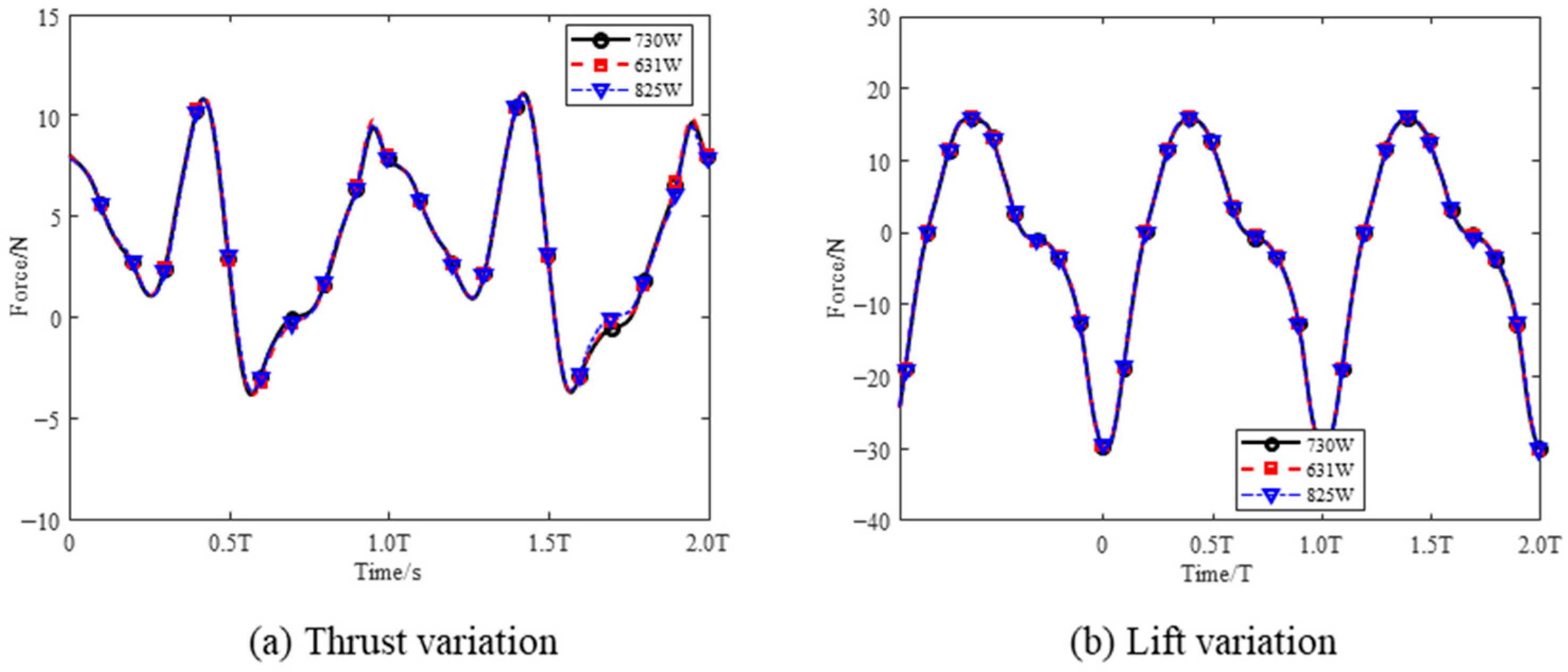
A mesh independence study is conducted by comparing the numerical results obtained using three mesh configurations with approximately 6.31, 7.30, and 8.25 million cells. As shown in Figure 5, the differences in lift and thrust predictions among the three meshes are less than 2%, indicating that the numerical solution is nearly insensitive to further mesh refinement. Therefore, the mesh with 7.30 million cells is adopted for subsequent simulations to achieve a balance between computational efficiency and numerical accuracy.
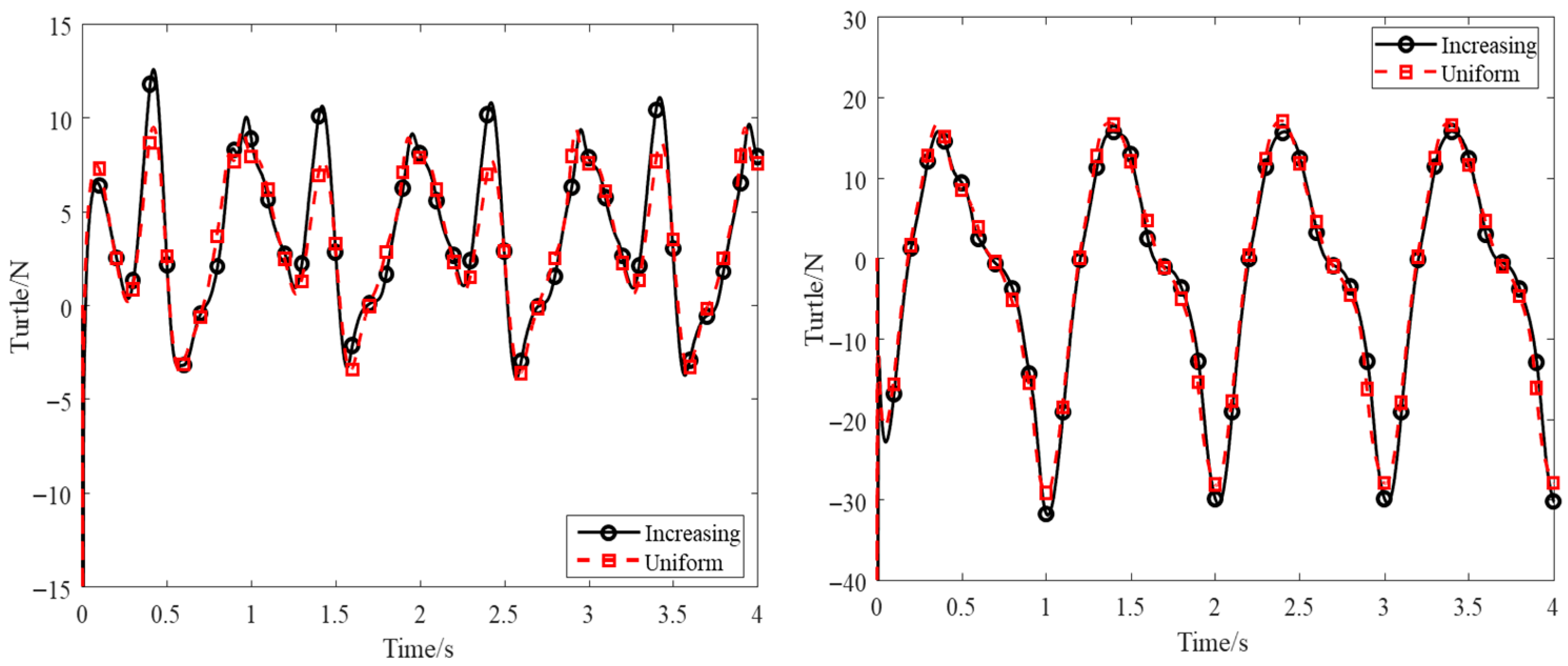
Figure 6 compares the thrust performance of the spanwise increasing twist and the uniform twist angle, where the former emulates the twist mechanism described in Section 2.2. Although both methods exhibit similar periodic fluctuations, the increasing twist angle along the wingspan enhances peak thrust by 25% at specific times.

3.3. Analysis of Results

To further elucidate the effects of the spanwise increasing twist angle on propulsion performance and flow vortex evolution, a series of parametric studies was conducted with varying maximum values of the spanwise increasing twist angle.
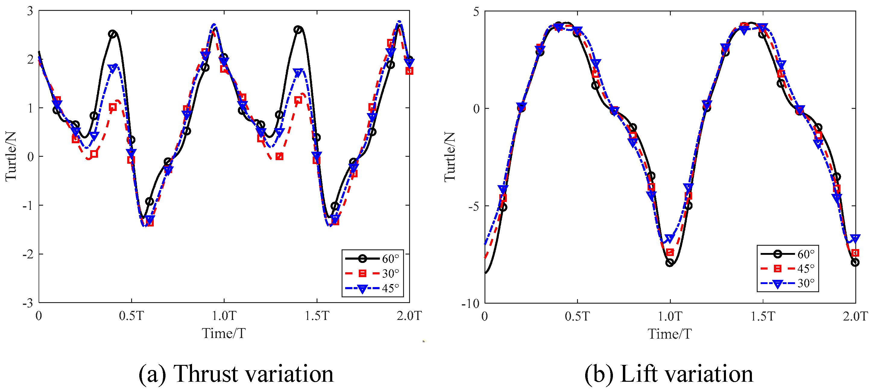
Figure 7 shows the variations in thrust and lift for the spanwise increasing twist angles with maximum values of 30°, 45°, and 60°. In all cases, the thrust exhibits periodic behavior consistent with the flapping cycle. Consistent with the results observed in Figure 6, the larger maximum twist angle leads to a significant increase in the thrust during the flapping phase. Compared with the 30° twist angle, the 60° twist angle produces approximately twice the peak thrust at 0.4 T, while the corresponding lift remains nearly unchanged. In addition, increasing the maximum twist angle does not result in greater reverse drag during the recovery stroke. By contrast, the maximum spanwise increasing twist angle has a relatively minor influence on lift, with the minimum lift decreasing by approximately 10%.
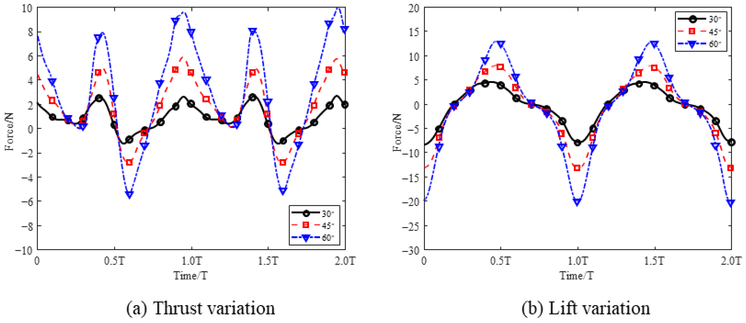
The above analysis demonstrates that the maximum twist angle effectively enhances propulsion efficiency. Based on this observation, Figure 8 further examines the influence of the longitudinal flapping angle on thrust and lift. As the longitudinal flapping angle increases, the peak-to-peak values of both thrust and lift increase significantly. When the longitudinal flapping angle is doubled, the peak-to-peak amplitudes of thrust and lift increase by approximately four times. Owing to the larger increase in positive thrust, the overall thrust over a flapping cycle shows a clear enhancement, whereas the lift exhibits a decreasing trend.
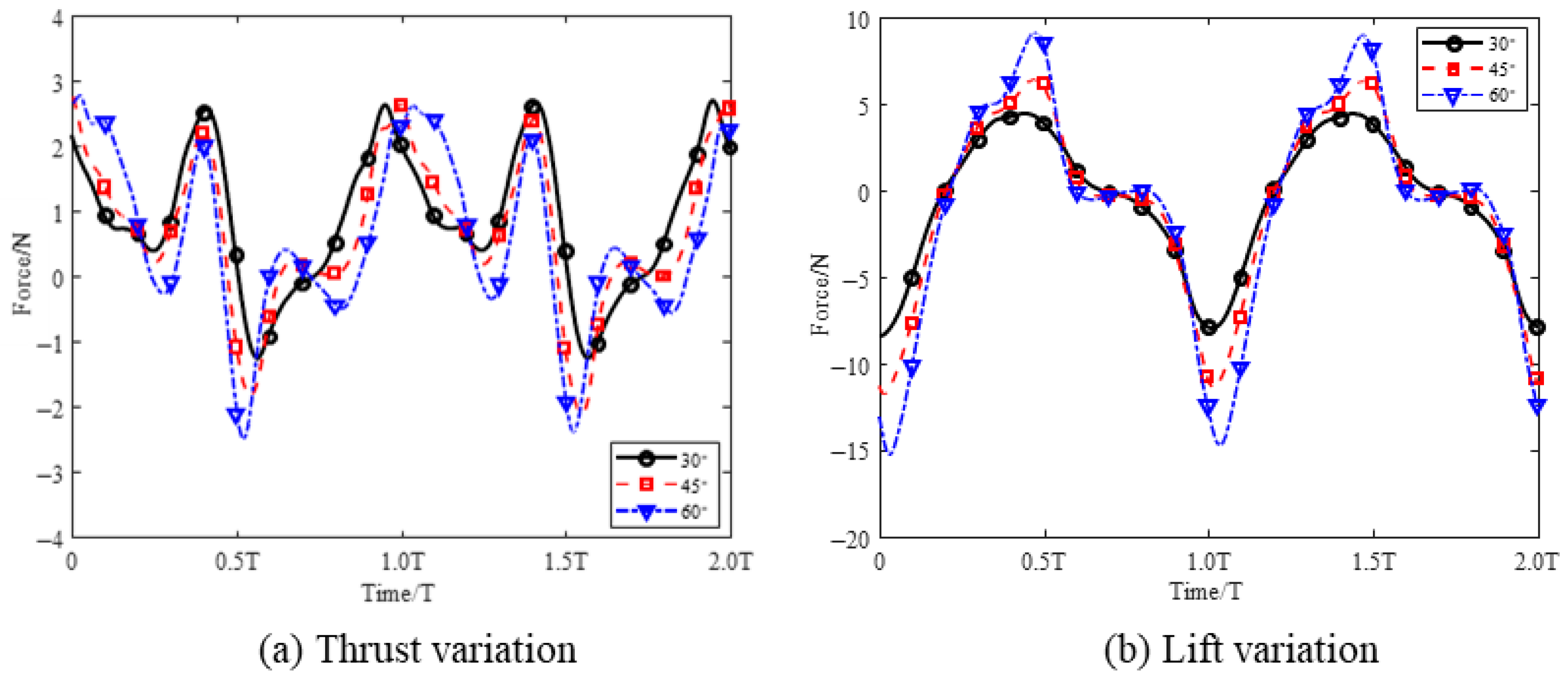
Figure 9 illustrates the effects of the elevation angle on thrust and lift. Unlike the twist angle and the longitudinal flapping angle, increasing the elevation angle suppresses the enhancement of thrust. Moreover, a larger elevation angle induces a phase lag in thrust generation, with both the peak thrust and peak lift delayed by approximately 0.1 T. The thrust oscillation also observed near 0.7 T for the 60° elevation case occurs when the wing reaches its lowest position and undergoes stroke reversal while experiencing maximum twist deformation. The large elevation angle requires a higher angular velocity within a fixed period, intensifying the unsteady interaction between wing motion and flow, which results in oscillatory force behavior.
In summary, the effects of different kinematic parameters on propulsive force exhibit significant coupling. Specifically, the longitudinal flapping angle contributes most prominently to thrust enhancement, with a peak thrust of up to 10 N. Increasing twist angle along the wingspan can effectively increase the maximum thrust during specific cyclic phases. The effect of increased elevation flapping angles of attack on thrust is relatively minor, but its impact on lift is significantly greater.
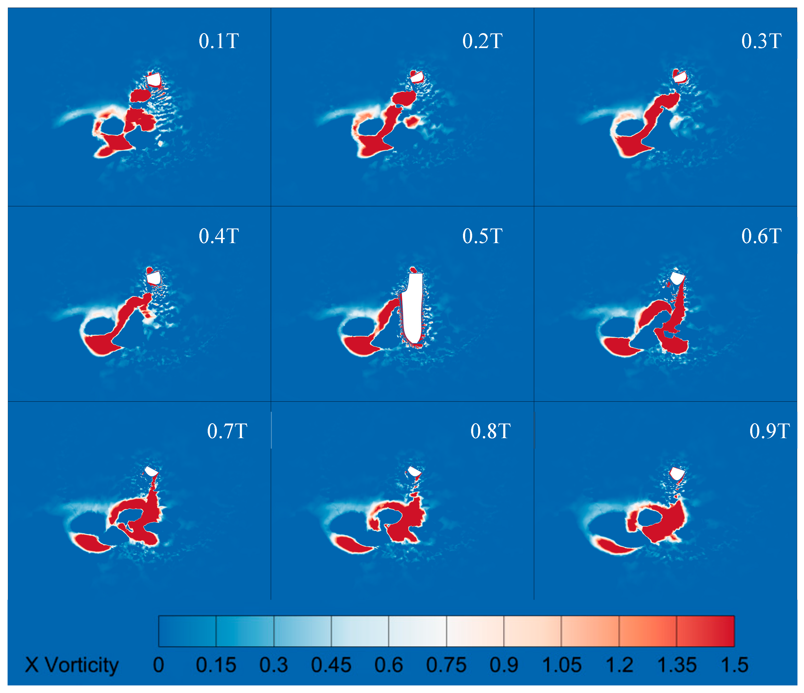
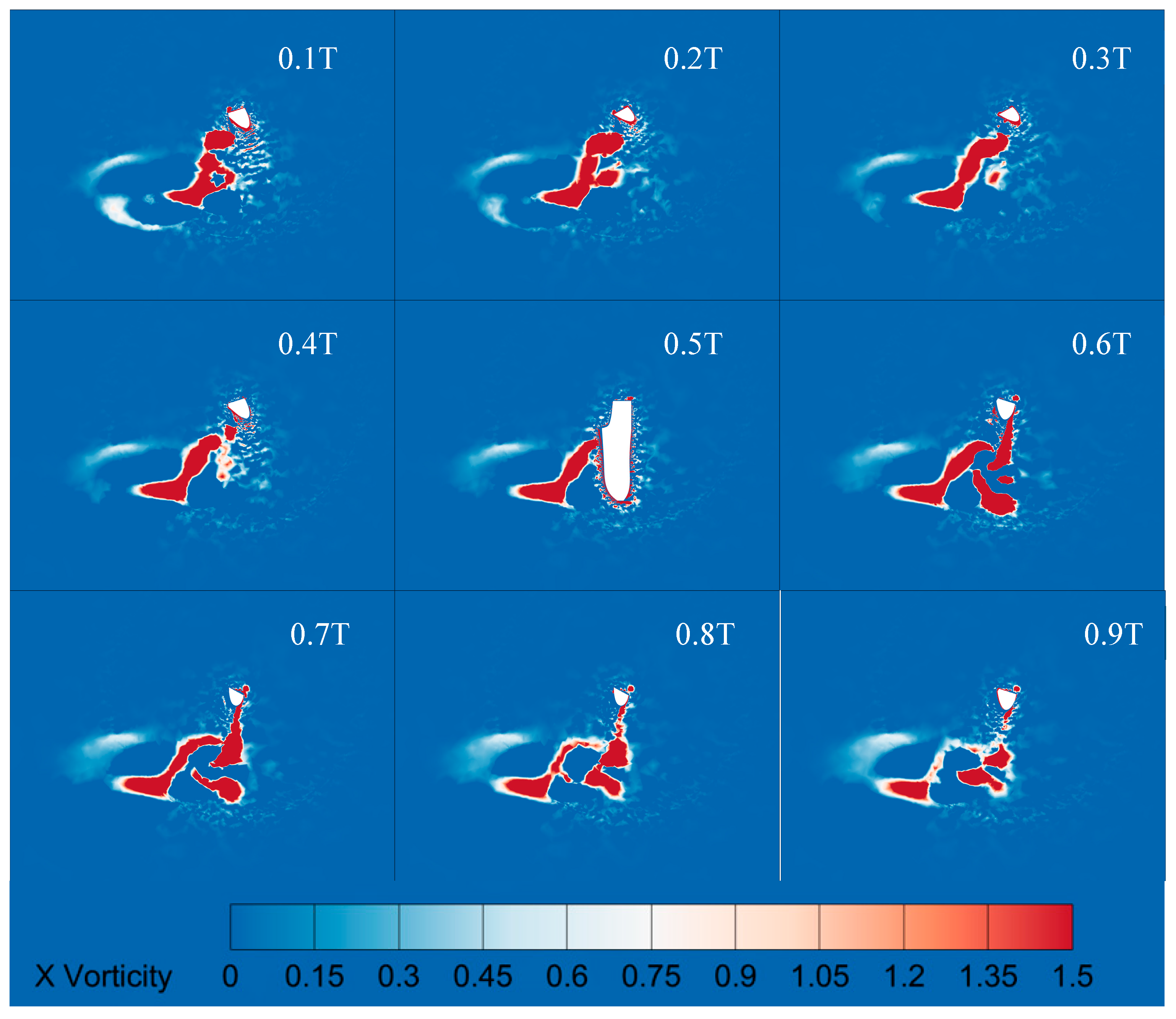
To further investigate the advantages of the increasing twist angle along the wingspan, Figure 10 and Figure 11 compare the vorticity contours on the x = 0 plane for both the spanwise increasing twist angle and the uniform twist. The results show that, during the interval from 0.3 T to 0.5 T, the spanwise increasing twist case is able to form and sustain a vortex structure with higher strength and larger spatial extent. When this vortex remains attached to the wing surface prior to shedding, it induces larger instantaneous peaks in both lift and thrust. A large area of high vorticity exists along the trailing edge of the flapping wing. This phenomenon matches the thrust variation shown in Figure 6. The thrust in the early stages of the increasing twist along the wingspan is significantly higher than that in the uniform twist.
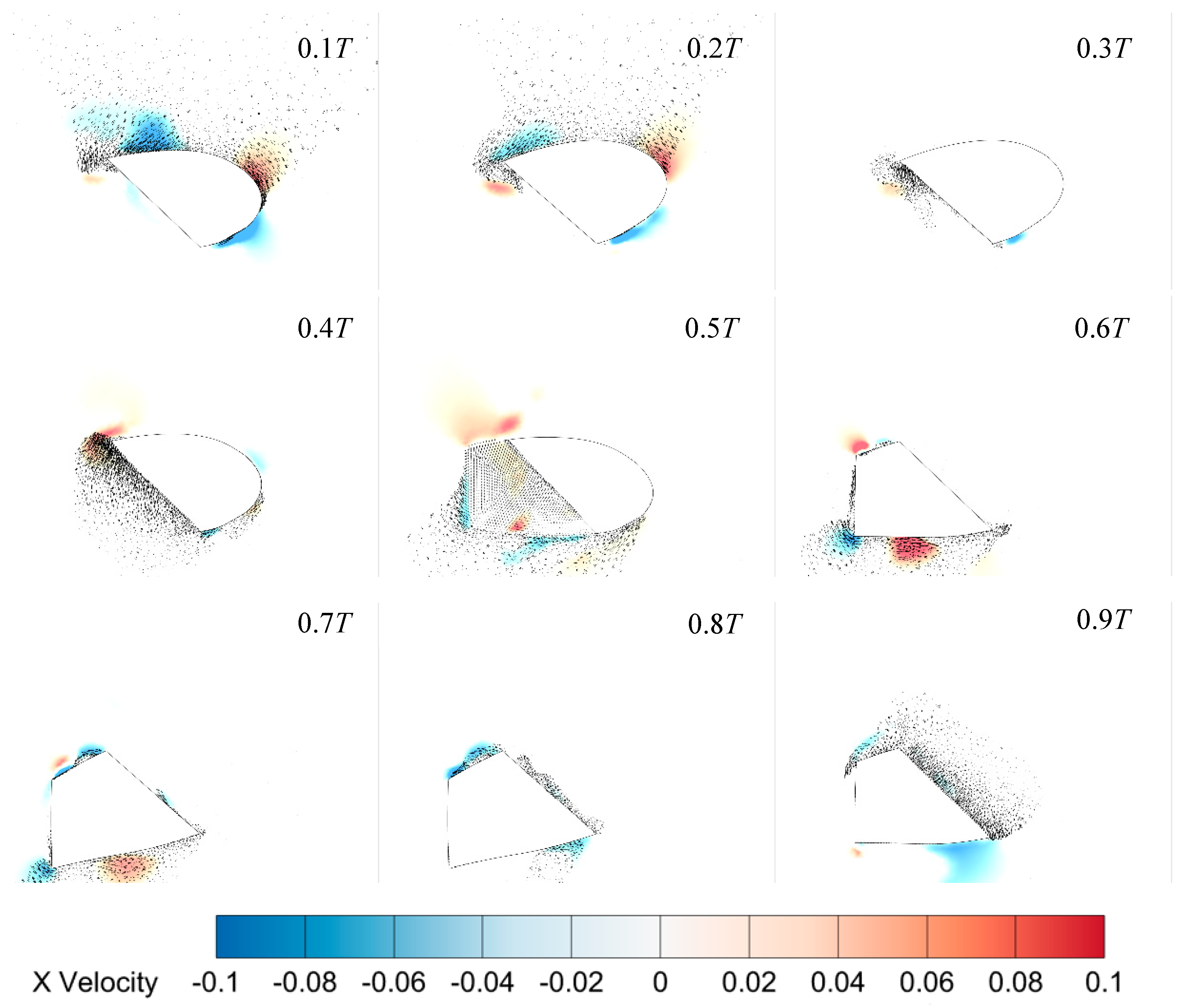
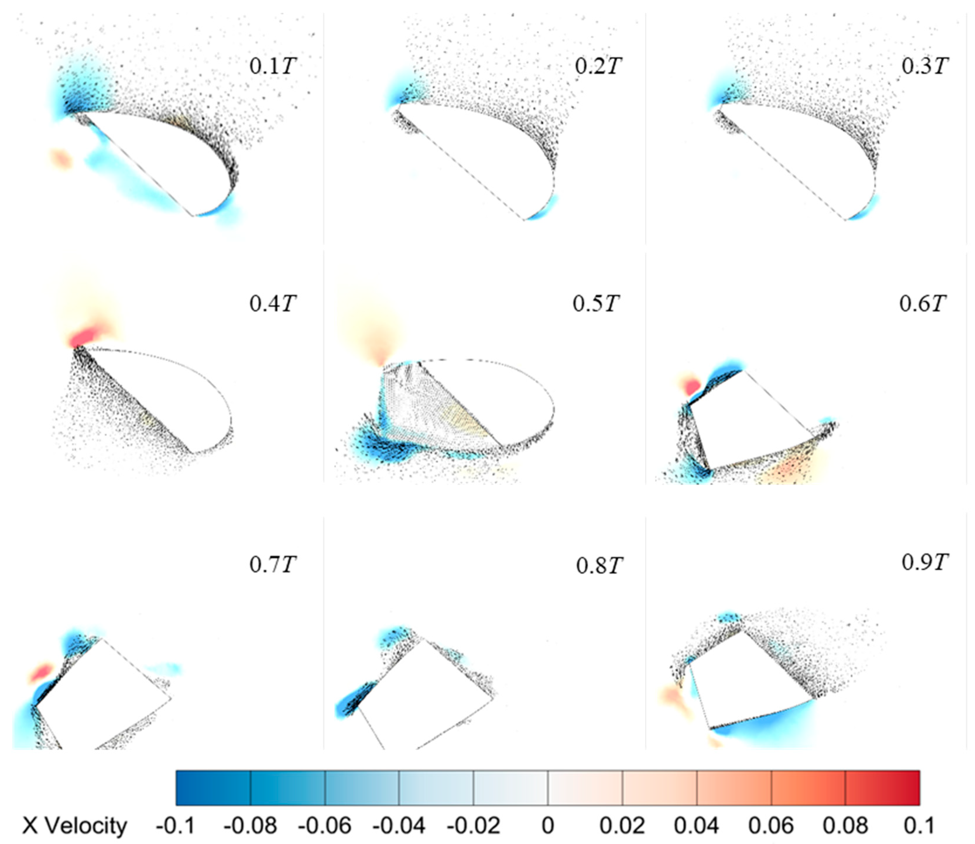
Figure 12 and Figure 13 show velocity vectors for the increasing twist along the wingspan and uniform twist. As shown in Figure 10, the flow behind the wing is stronger and more aligned with the forward direction. High-speed fluid near the wing surface in the spanwise increasing twist increases positive thrust during the first half of the cycle. In contrast, in the uniform rotation case, the flow is directed more upward and rearward, which reduces the effective thrust. The velocity contours also show that the increasing twist along the wingspan keeps more high-speed fluid close to the wing surface.

4. Experimental Testing

4.1. Experimental Design

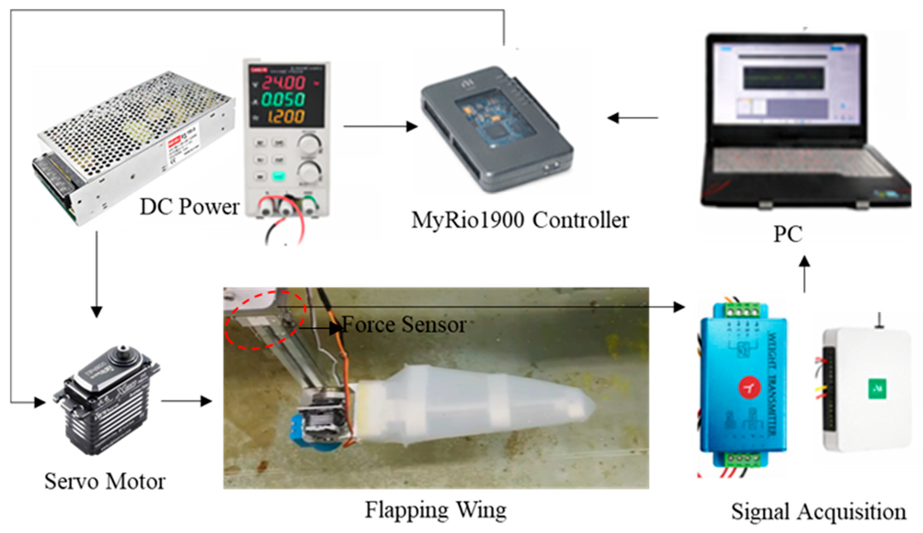
To validate the bio-inspired flapping wing mechanism and evaluate its thrust under low-frequency actuation, a prototype was fabricated and tested in a controlled water tank. Figure 14 presents the experimental setup and hardware architecture used for thrust measurements. The upper row illustrates the external power supply and control components, including the NI myRIO-1900 controller, which is manufactured by National Instruments in Austin, TX, USA. A regulated DC power supply provided electrical power to the servomotor, the force sensor, and the controller. The servomotor is a waterproof model produced by GXSERVO in Dongguan, China, and the force sensor is manufactured by DAYSENSOR in Bengbu, China. The output signals from the force sensor were first processed by a signal conditioning module, which converted the raw sensor outputs into standardized voltage signals. These conditioned signals were then acquired by the NI myRIO-1900 controller, enabling high-speed, synchronized data acquisition. All measured data were transmitted to a PC running LabVIEW, which provides real-time monitoring, control, and data logging functions.
The lower part of Figure 14 shows the flapping wing experimental platform submerged in a water tank. The bio-inspired flapping wing was actuated by a servomotor and mounted on a support structure integrated with a force sensor, allowing for direct measurement of thrust over the flapping cycle. Electrical cables connected the submerged experimental platform to the external power supply and data acquisition units, ensuring stable power delivery and reliable signal transmission. This integrated setup enabled repeatable experiments and accurate measurement of hydrodynamic forces and wing kinematics under controlled laboratory conditions.
In this study, the gear transmission ratios were designed based on the mechanism’s spatial layout to achieve approximately linear spanwise twist in the flapping wing. The wing root was directly connected to the servomotor through a linkage mechanism. The first gear pair was configured with a transmission ratio of 27:15. In contrast, the second gear pair employed a ratio of 22:15. It should be noted that the transmission mechanism was fabricated using a 3D printing process, with a dimensional tolerance of approximately 0.1 mm, which may introduce minor deviations in the actual gear meshing and angular transmission. In addition, the flapping motion was driven by a servomotor with a rated torque of approximately 4 N·m, which is sufficient to overcome hydrodynamic loads and structural resistance during operation but may also lead to slight compliance under dynamic loading.
Although the gear transmission ratios do not yield a strictly linear twist distribution, the mechanism was designed to generate a monotonically varying and increasing twist angle along the wingspan. The discrete nature of the gear transmission introduces local deviations from linearity, while the silicone skin’s elastic properties help smooth deformation along the span. Given that the objective of this study was to examine the hydrodynamic effects associated with a spanwise twist angle rather than an exact linear twist law, the resulting twist distribution was considered mechanically reasonable and sufficient for the present investigation.
It should be noted that a formal uncertainty quantification was not conducted in this study. However, uncertainty was mitigated through controlled numerical and experimental procedures. In the numerical simulations, mesh quality and time-step stability were carefully monitored, and key flow features and thrust trends were found to be insensitive to small variations in numerical parameters. In the experiments, repeated measurements under identical operating conditions showed consistent periodic thrust patterns.

4.2. Results Comparison

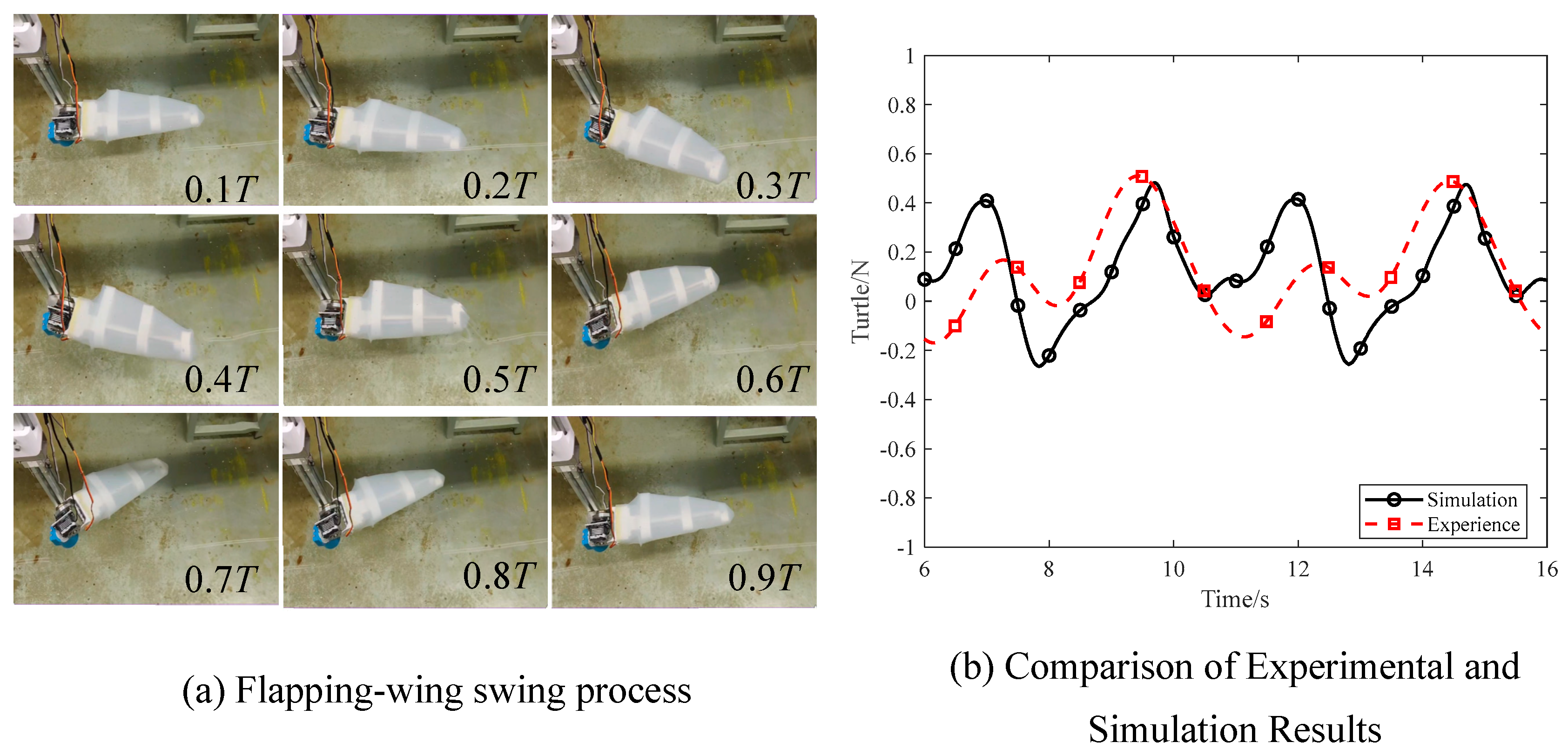
Previous kinematic studies based on underwater video observations have reported that the flapping frequency of sea turtle wings typically ranges from approximately 0.3–0.8 Hz during steady swimming, and may increase to around 1–2 Hz during acceleration or maneuvering phases. To validate the effectiveness of the designed bionic flapping wing, thrust measurements were first conducted using a single forelimb prototype under an input flapping frequency of 0.2 Hz. The flapping frequency of 0.2 Hz was deliberately selected as a quasi-static and mechanically reliable operating condition for experimental validation. At higher actuation frequencies, the current prototype and test rig were prone to increased transmission friction, structural vibration, and motor torque saturation. These effects can introduce significant uncertainties in thrust measurements. Operating at a lower frequency ensured stable motion execution, repeatable kinematics, and sufficient temporal resolution for force acquisition and motion recording. Since the goal of the experiment was to validate numerical trends and phase relationships rather than achieve realistic swimming speeds, the chosen frequency was suitable for preliminary experimental validation.
A camera was employed to record the periodic motion process, and the corresponding deformation patterns and motion cycles are illustrated on the left of Figure 15. The comparison results between the experimentally measured thrust and the numerical simulation are shown on the right of Figure 15. The experiments reproduce the main trends observed in the simulations. Despite the uncertainties arising from experimental drag and variations in twist amplitude, the motion patterns and peak thrust values remain consistent, indicating the reliability of the proposed spanwise increasing twist flapping wing design.
The comparison in Figure 15 reveals a reasonable agreement between the numerical and experimental results in terms of waveform and trend. Quantitatively, the error of the average thrust between the two curves is approximately 5.3%, and the relative error at the peak-to-peak thrust is about 5.5%. This discrepancy is primarily due to unmodeled mechanical friction in the gear train and the passive deformation of the soft silicone skin. Despite these magnitude differences, the consistent variation trends validate the effectiveness of the increasing twist angle along the wingspan design.
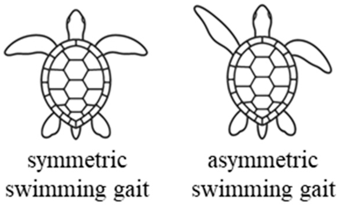
Biological observations of sea turtle swimming behavior reveal two primary gaits, as illustrated in Figure 16. The first is a synchronous flapping gait, in which both flapping wings move in phase, commonly observed during high-speed cruising. The second is an alternating flapping gait, frequently seen in the swimming patterns of juvenile sea turtles.
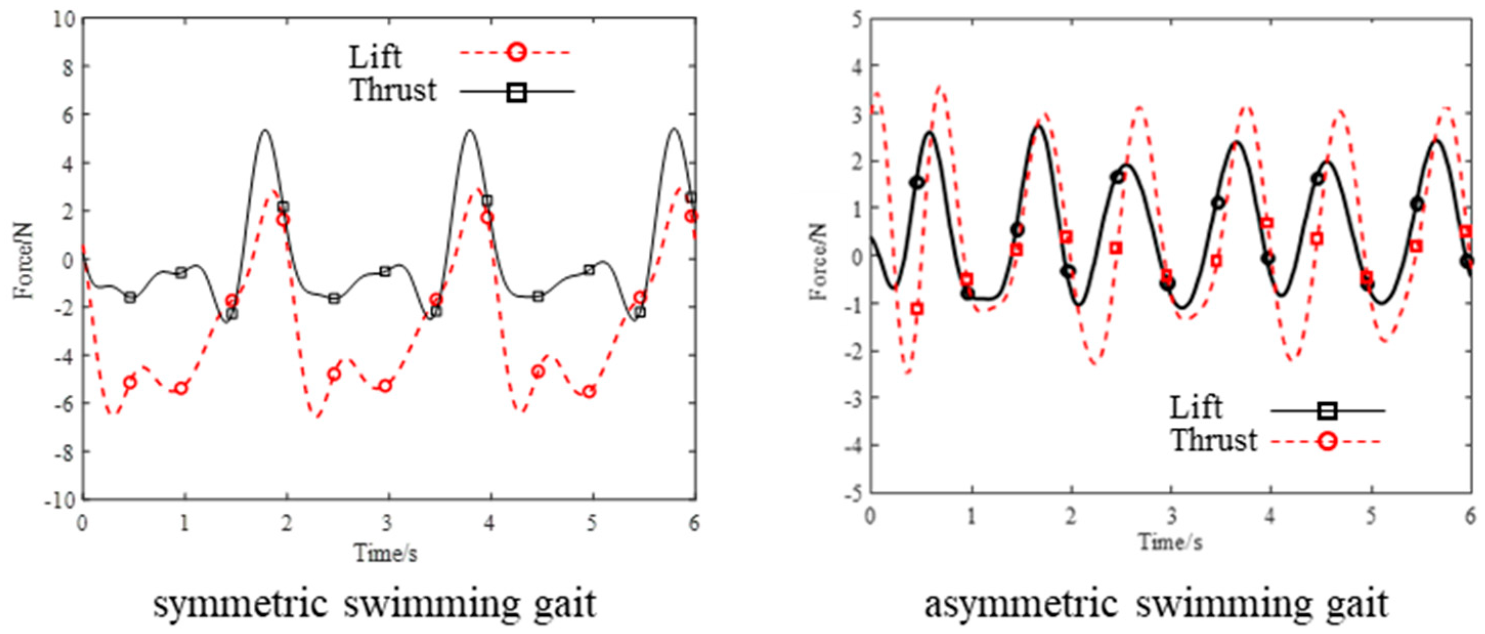
Considering that real sea turtles employ two primary swimming gaits, namely asymmetric alternating flapping and symmetric flapping, Figure 17 analyzes the cooperative propulsion performance of a dual-wing system under these two modes. The corresponding 3-DOF motions are based on the real sea turtle swimming equations provided by Van [38,39], with a frequency set to 0.5 Hz. The results for the symmetric swimming indicate that the symmetric swimming gait can generate a larger thrust force, with a peak thrust of 5.5 N. However, the lift curve is dominated by negative lift, and the maximum negative lift reaches −6.3 N. The results for the asymmetric swimming gait show the opposite trend: the maximum thrust decreases to approximately 2.5 N, while the lift is significantly enhanced, with the maximum positive lift reaching around 3.5 N. So, the symmetric swimming gait has a distinct advantage for rapid locomotion, whereas the asymmetric swimming gait is more suitable for heave motion.

5. Conclusions

In this study, a bio-inspired flapping wing propulsion system was studied using CFD simulations and experiments. The main conclusions were as follows:
  • The increasing twist angle along the wingspan produced a higher peak thrust than the uniform rotation at certain phases of the flapping cycle. A larger longitudinal flapping angle (e.g., 60°) gives stronger forward thrust but also increases reverse drag, and the longitudinal motion had the strongest effect on thrust.
  • Velocity and vorticity fields showed that the increasing twist angle along the wingspan generates forward-directed high-speed flow. During the first half of the cycle, more high-speed flow stays close to the wing surface, and this improves positive thrust.
  • Experiments on the flapping wing prototype demonstrate periodic thrust variations that are consistent with the CFD. Based on the validated single-limb performance, comparative experiments on dual-limb flapping gaits are further conducted, revealing distinct trade-offs between thrust generation and vertical force characteristics under symmetric and asymmetric swimming patterns.
However, several limitations should be noted. The present numerical and experimental studies are conducted under a fixed-reference framework and mainly focus on the comparative hydrodynamic performance of the flapping-wing mechanism, rather than predicting the free-swimming behavior of a complete robotic system. In addition, the experimental validation was performed at a relatively low flapping frequency due to hardware and testing constraints, which is sufficient for verifying mechanical feasibility and thrust trends but does not fully replicate biological swimming conditions. Future work will focus on a systematic investigation of propulsion efficiency under coupled multi-degree-of-freedom motions. In addition, a fully integrated sea turtle-inspired robotic platform will be developed, and comprehensive underwater experiments will be conducted to evaluate its propulsion performance and maneuverability. Finally, the flapping wing video is provided in the Supplementary File.

Supplementary Materials

The following supporting information can be downloaded at: https://www.mdpi.com/article/10.3390/machines14010102/s1.

Author Contributions

Conceptualization, M.G. and P.M.; methodology, D.N.; software, M.G. and X.Z.; validation, M.G. and J.L.; formal analysis, M.G.; investigation, J.L.; resources, D.N.; data curation, M.G.; writing—original draft preparation, M.G.; writing—review and editing, P.M.; visualization, M.G. and J.L.; supervision, D.N.; project administration, P.M.; funding acquisition, P.M. and D.N. All authors have read and agreed to the published version of the manuscript.

Funding

This work was funded by the National Natural Science Foundation of China under Grant no. 52205293, the Shandong Provincial Natural Science Foundation under Grant No. ZR2021QE189, and the Taishan Scholar Foundation of Shandong Province under Grant No. tsqn202211062.

Informed Consent Statement

Not applicable.

Data Availability Statement

The data supporting reported results are not stored in any publicly archived datasets. The readers can contact the corresponding author for any further clarification of the results obtained.

Conflicts of Interest

The authors declare no conflicts of interest.

Abbreviations

The following abbreviations are used in this manuscript:
DOFDegrees of freedom
CFDComputational fluid dynamics
UDFUser-defined function

References

  1. Zhong, Q.; Zhu, J.; Fish, F.E.; Kerr, S.J.; Downs, A.M.; Bart-Smith, H.; Quinn, D.B. Tunable stiffness enables fast and efficient swimming in fish-like robot. Sci. Robot. 2021, 6, eabe4088. [Google Scholar] [CrossRef]
  2. Park, Y.J.; Huh, T.M.; Park, D.; Cho, K.J. Design of a variable-stiffness flapping mechanism for maximizing the thrust of a bio-inspired underwater robot. Bioinspir. Biomim. 2014, 9, 036002. [Google Scholar] [CrossRef]
  3. Sheng, C.; Sun, Q.; Huang, H. Motion modeling and hydrodynamic analysis of pectoral fin. Ocean Eng. 2024, 310, 118769. [Google Scholar] [CrossRef]
  4. Li, Z.; Chao, X.; Hameed, I.; Li, J.; Zhao, W.; Jing, X. Biomimetic omnidirectional multi-tail underwater robot. Mech. Syst. Signal Proc. 2022, 173, 109056. [Google Scholar] [CrossRef]
  5. Xiang, Y.; Gu, L.; Ye, K.; Zhang, Z.; Gong, Z.; Tao, B. A variable stiffness fin for manta ray-inspired robots with two motion modals. IEEE Robot. Autom. Lett. 2025, 10, 2271–2278. [Google Scholar] [CrossRef]
  6. Lighthill, J. Mathematical Biofluiddynamics; Society for Industrial and Applied Mathematics: Philadelphia, PA, USA, 1975. [Google Scholar]
  7. Tong, Z.; Jin, X.; Gao, H.; Zhang, Y.; Deng, Z. A novel robotic fish based on elastic beam actuation mechanism. Ocean Eng. 2025, 327, 120940. [Google Scholar] [CrossRef]
  8. Jia, A.; Sun, R.; Guan, Y.; Qin, X.; Liu, Y.; Yang, S.; Zhuang, Z.; Kang, R.; Dai, J.S. Flexible wing dynamics of an underwater gliding robot. In Proceedings of the 6th International Conference on Reconfigurable Mechanisms and Robots, Chicago, IL, USA, 24–27 June 2024; pp. 614–620. [Google Scholar]
  9. Chao, X.; Hameed, I.; Navarro-Alarcon, D.; Jing, X. A controllable nonlinear bistable “fishtail” boosting robotic swimmer with excellent maneuverability and high energy efficiency. Soft Robot. 2024. [Google Scholar] [CrossRef]
  10. Chivkula, P.; Rodwell, C.; Tallapragada, P. Hopping potential wells and gait switching in a fish-like robot with a bistable tail. Extreme Mech. Lett. 2024, 72, 102239. [Google Scholar] [CrossRef]
  11. Deng, H.B.; Xu, Y.Q.; Chen, D.D.; Dai, H.; Wu, J.; Tian, F.B. On numerical modeling of animal swimming and flight. Comput. Mech. 2013, 52, 1221–1242. [Google Scholar] [CrossRef]
  12. Ju, I.; Yun, D. Hydraulic variable stiffness mechanism for swimming locomotion optimization of soft robotic fish. Ocean Eng. 2023, 286, 115551. [Google Scholar] [CrossRef]
  13. Tang, Y.; Qin, L.; Li, X.; Chew, C.M.; Zhu, J. A frog-inspired swimming robot based on dielectric elastomer actuators. In Proceedings of the IEEE/RSJ International Conference on Intelligent Robots and Systems, Vancouver, BC, Canada, 24–28 September 2017; pp. 2403–2408. [Google Scholar]
  14. Qiu, H.; Chen, L.; Ding, Z.; Wang, Z.; Chen, Y.; Zhou, F.; Li, T. Multi-fins coordination: Impact on the forward locomotion of a bionic Ostraciiform robot. Ocean Eng. 2025, 333, 121523. [Google Scholar] [CrossRef]
  15. Lin, Z.; Zheng, W.; Zhang, J.; Ou, W.; Yang, C.; Huang, H.; Xu, W.; Yang, Z.; Zhou, W.; Zhang, Y. Mudskipper-inspired amphibious robotic fish enhances locomotion performance by pectoral-caudal fins coordination. Cell Rep. Phys. Sci. 2023, 4, 101589. [Google Scholar] [CrossRef]
  16. Huang, H.; Sheng, C.; Wu, J.; Wu, G.; Zhou, C.; Wang, H. Hydrodynamic analysis and motion simulation of fin and propeller driven manta ray robot. Appl. Ocean Res. 2021, 108, 102528. [Google Scholar] [CrossRef]
  17. Rahman, M.M.; Toda, Y.; Miki, H. Computational study on a squid-like underwater robot with two undulating side fins. J. Bionic Eng. 2011, 8, 25–32. [Google Scholar] [CrossRef]
  18. Liu, R.; Wang, L.; Jin, J.; Zhao, H.; Zhang, A.; Chen, D. A novel 3-DoF piezoelectric robotic pectoral fin: Design, simulation, and experimental investigation. Smart Mater. Struct. 2022, 31, 065003. [Google Scholar] [CrossRef]
  19. Xing, C.; Cao, Y.; Cao, Y.; Pan, G.; Huang, Q. Asymmetrical oscillating morphology hydrodynamic performance of a novel bionic pectoral fin. J. Mar. Sci. Eng. 2022, 10, 289–307. [Google Scholar] [CrossRef]
  20. Zhang, T.; Hu, Q.; Li, S.; Shi, X.; Zeng, Y.; Zu, S.; Zhao, J.; Wei, H.; Zhang, J.; Guo, C. Influence of hydrofoil motion patterns on the hydrodynamic performance of undulating fin for biomimetic underwater robots. Ocean Eng. 2024, 314, 119694. [Google Scholar] [CrossRef]
  21. Sun, Q.; Wu, J.; Sheng, C.; Hu, S.; Wang, Z.; Huang, H. Design and implementation of multi-level linkage mechanism bionic pectoral fin for manta ray robot. Ocean Eng. 2023, 284, 115152. [Google Scholar] [CrossRef]
  22. Zhang, D.; Huang, Q.G.; Pan, G.; Yang, L.M.; Huang, W.X. Vortex dynamics and hydrodynamic performance enhancement mechanism in batoid fish oscillatory swimming. J. Fluid Mech. 2021, 930, A28. [Google Scholar] [CrossRef]
  23. Yu, Z.; Li, K.; Ji, Y.; Yang, S.X. Fast motion performance of a bionic ray robot with serial pectoral fins. IEEE Robot. Autom. Lett. 2023, 8, 7218–7225. [Google Scholar] [CrossRef]
  24. Zhang, Y.; Han, X.; Hu, Y.; Chen, X.; Li, Z.; Gao, F.; Chen, W. Dual-function flapping hydrofoil: Energy capture and propulsion in ocean waves. Renew. Energy 2024, 222, 119956. [Google Scholar] [CrossRef]
  25. Dong, Y.; Song, B.; Xue, D.; Yang, W. 3D numerical simulation of a hovering hummingbird-inspired flapping wing with dynamic morphing. J. Appl. Fluid Mech. 2022, 15, 873–888. [Google Scholar] [CrossRef]
  26. Dong, Y.; Song, B.; Xue, D.; Li, Y.; Yang, W.; Ding, H. Numerical study of the aerodynamics of a hovering hummingbird’s wing with dynamic morphing. Int. J. Aerosp. Eng. 2022, 2022, 5433184. [Google Scholar] [CrossRef]
  27. Shimooka, T.; Kakogawa, A.; Tanaka, H. An agile robotic penguin driven by submersible geared servomotors: Various maneuvers by active feathering of the wings. In Proceedings of the IEEE/RSJ International Conference on Intelligent Robots and System, Abu Dhabi, United Arab Emirates, 14–18 October 2024; pp. 303–308. [Google Scholar]
  28. Guo, Y.; Yang, W.; Dong, Y.; Xuan, J. Numerical investigation of an insect-scale flexible wing with a small amplitude flapping kinematics. Phys. Fluids 2022, 34, 081903. [Google Scholar] [CrossRef]
  29. Shen, Y.; Ding, Z.; Wang, X.; Mao, Z.; Huang, Z.; Chen, B. Biomimetic hydrofoil propulsion: Harnessing the propulsive capabilities of sea turtles and penguins for robotics. Biomimetics 2025, 10, 272. [Google Scholar] [CrossRef]
  30. Fan, X.; Gehrke, A.; Breuer, K. Wing twist and folding work in synergy to propel flapping wing animals and robots. In Proceedings of the IEEE/RSJ International Conference on Intelligent Robots and Systems, Abu Dhabi, United Arab Emirates, 14–18 October 2024; pp. 13915–13921. [Google Scholar]
  31. Harada, N.; Oura, T.; Maeda, M.; Shen, Y.; Kikuchi, D.M.; Tanaka, H. Kinematics and hydrodynamics analyses of swimming penguins: Wing bending improves propulsion performance. J. Exp. Biol. 2021, 224, jeb242140. [Google Scholar] [CrossRef]
  32. Chu, D.H.; Liu, X.B.; Zhang, M. J Research on turtle hydrofoil motion principle and bionics. In Proceedings of the IEEE International Conference on Automation and Logistics, Jinan, China, 18–21 August 2007; pp. 2373–2378. [Google Scholar]
  33. Yan, Y.; Wang, X.; Qi, X.; Hou, J.; Chen, C.; Ma, J.; Xing, H.; Chen, Y.; Zhao, Y. Development of a turtle-inspired robot with variable stiffness hydrofoils. In Proceedings of the IEEE International Conference on Mechatronics and Automation, Guilin, China, 7–10 August 2022; pp. 493–498. [Google Scholar]
  34. Chu, Y.; Wang, Y.; Lv, Z.; Zhou, Y.; Li, X.; Ma, M.; Zhu, C.; Yu, T. An innovative underdriven multi-degree-of-freedom sea turtle hydrofoil design. Bioinspir. Biomim. 2025, 20, 3. [Google Scholar]
  35. Li, X.; He, W.; Li, J.; Xia, D.; Luo, X.; Shi, Y.; Ji, X.; Yang, Y. Design and development of an underwater robot inspired by sea turtles. In Proceedings of the IEEE International Conference on Mechatronics and Automation, Tianjin, China, 4–7 August 2024; pp. 1723–1728. [Google Scholar]
  36. Van der Geest, N.; Garcia, L. Employing robotics for the biomechanical validation of a prosthetic flipper for sea turtles as a substitute for animal clinical trials. Biomechanics 2023, 3, 401–414. [Google Scholar] [CrossRef]
  37. Van der Geest, N.; Garcia, L.; Borret, F.; Nates, R.; Gonzalez, A. Soft-robotic green sea turtle (Chelonia mydas) developed to replace animal experimentation provides new insight into their propulsive strategies. Sci. Rep. 2023, 13, 11983. [Google Scholar] [CrossRef]
  38. Van der Geest, N.; Garcia, L.; Nates, R.; Godoy, D.A. New insight into the swimming kinematics of wild Green sea turtles (Chelonia mydas). Sci. Rep. 2022, 12, 18151. [Google Scholar] [CrossRef]
  39. Ozbek, E.; Ekici, S.; Karakoç, T.H. A comprehensive review of state-of-art FishBAC—Fishbone active camber morphing wing surfaces–: A promising morphing method. Aircr. Eng. Aerosp. Technol. 2024, 96, 983–993. [Google Scholar] [CrossRef]
  40. Luo, B.; Cui, W.; Li, W. Active and robust twisting morphing wings with geometric constraints for flying or swimming robots. IEEE ASME Trans. Mechatron. 2022, 27, 4205–4210. [Google Scholar] [CrossRef]
  41. Cai, Y.; Chen, L.; Bi, S.; Li, G.; Zhang, H. Bionic flapping pectoral fin with controllable spatial deformation. J. Bionic Eng. 2019, 16, 916–930. [Google Scholar] [CrossRef]
  42. Chu, D. Research on the Hydrofoil Propulsion Principle and Its Bionic System; Harbin Engineering University: Harbin, China, 2009. [Google Scholar]
  43. Van der Geest, N.; Garcia, L.; Nates, R.; Borrett, F.A. New insights into sea turtle propulsion and their cost of transport point to a potential new generation of high-efficient underwater drones for ocean exploration. J. Mar. Sci. Eng. 2023, 11, 1944. [Google Scholar] [CrossRef]
Figure 1. Sea turtle forelimb flapping motion frames [42] and comparison of spanwise increasing twist distributions.
Machines 14 00102 g001
Figure 2. Structural diagram of a 3-DOF sea turtle forelimb mechanism.
Machines 14 00102 g002
Figure 3. Three DOF movement patterns of bionic turtles.
Machines 14 00102 g003
Figure 4. Finite element model and flapping wing deformation.
Machines 14 00102 g004
Figure 5. Grid independence verification.
Machines 14 00102 g005
Figure 6. Comparison of thrust and lift forces between spanwise increasing twist angle and uniform twist angle.
Machines 14 00102 g006
Figure 7. Comparison of thrust and lift forces under different twist angles.
Machines 14 00102 g007
Figure 8. Comparison of thrust and lift forces under different longitudinal flapping angles.
Machines 14 00102 g008
Figure 9. Comparison of thrust and lift forces under different elevation flapping angles.
Machines 14 00102 g009
Figure 10. Vorticity contours on the x = 0 plane under the increasing spanwise twist.
Machines 14 00102 g010
Figure 11. Vorticity contour on the x = 0 plane for the uniform twist.
Machines 14 00102 g011
Figure 12. Velocity vectors and velocity contours on the x = 0 for the spanwise increasing twist.
Machines 14 00102 g012
Figure 13. Velocity vectors and velocity contours on the x = 0 for the uniform twist.
Machines 14 00102 g013
Figure 14. Underwater experimental platform for flapping wing.
Machines 14 00102 g014
Figure 15. Comparison of experimental results.
Machines 14 00102 g015
Figure 16. Schematic diagrams of the two swimming gaits.
Machines 14 00102 g016
Figure 17. Propulsive performance of the flapping wing under different gaits.
Machines 14 00102 g017
Disclaimer/Publisher’s Note: The statements, opinions and data contained in all publications are solely those of the individual author(s) and contributor(s) and not of MDPI and/or the editor(s). MDPI and/or the editor(s) disclaim responsibility for any injury to people or property resulting from any ideas, methods, instructions or products referred to in the content.