Article

Magnetic Circuit Analysis and Design Optimized for Cost-Effectiveness of Surface-Inserted Rare Earth Consequent-Pole Permanent Magnet Machines

1
College of Electronic and Electrical Engineering, Henan Normal University, Xinxiang 453007, China
2
Faculty of Electrical Engineering and Information Technology, Otto von Guericke University Magdeburg, 39106 Magdeburg, Germany
3
College of Automation, Northwestern Polytechnical University, Xi’an 710129, China
4
Altair Engineering Software (Shanghai) Co., Ltd., Shanghai 200080, China
*
Author to whom correspondence should be addressed.
Machines 2025, 13(9), 873; https://doi.org/10.3390/machines13090873
Submission received: 12 August 2025 / Revised: 12 September 2025 / Accepted: 17 September 2025 / Published: 19 September 2025
(This article belongs to the Special Issue Wound Field and Less Rare-Earth Electrical Machines in Renewables)

Abstract

In consequent-pole permanent magnet (CPPM) machines, the configuration where PM poles and iron poles are alternately arranged causes distortion in the air-gap magnetic field. This results in significant differences in magnetic circuit characteristics compared to conventional PM machines. To address the requirements of reducing torque ripple and enhancing average output torque, the cogging torque and optimization methods for CPPM machines were investigated. A general analytical model for cogging torque was established. This model accounts for asymmetric pole configurations and is particularly well-suited for analyzing CPPM machines. The mechanism through which the consequent-pole (CP) structure improves the utilization rate of PM material was explored, and the parameters influencing the main flux were analyzed. By replacing PMs with soft magnetic materials, the conventional topology of a 12-slot/8-pole surface-inserted PM machine with stator skewing was directly converted into a CP topology. Performance optimization was conducted based on this original scheme. This approach ensures manufacturing convenience while maximizing the sharing of identical components. Simulation results demonstrate that, compared to the benchmark machine, the optimized CPPM machine uses only 60.16% of the PM material while producing 88.19% of the electromagnetic torque, resulting in a 46.61% increase in torque generated per unit volume of PM material. Finally, the benchmark and optimized CPPM prototypes were fabricated, and their torque output capabilities were tested. The finite element simulation results and the measured data show good consistency, validating the correctness of the theoretical analysis and the effectiveness of the finite element model. This study provides a theoretical basis and engineering reference for the performance analysis and optimal design of CPPM machines.

1. Introduction

Rare earth permanent magnet (REPM) machines exhibit distinct advantages in efficiency, power density, dynamic performance, and maintenance costs, rendering them particularly suitable for applications demanding high efficiency, energy conservation, high-precision control, and space-constrained installations [1,2,3,4]. However, the fabrication costs of REPM machines remain relatively high at the current development stage [5,6].
REPM machines primarily denote machines employing rare earth PMs such as Neodymium Iron Boron (NdFeB) or Samarium Cobalt (SmCo). The proportional composition of their cost structure exhibits significant variation depending on factors including machine type, power rating, application scenario, material price fluctuations, manufacturing processes, and production volume. Taking REPM machines for new energy vehicle traction as an illustrative case, high-performance NdFeB PMs constitute the dominant cost component [7], accounting for approximately 30–50% of the total machine cost. Design objectives targeting high power density and high efficiency typically necessitate either increased material consumption or higher-performance rare earth PMs. Notably, higher-grade materials with elevated coercivity and remanence command premium unit pricing. Consequently, reducing rare earth consumption represents one effective approach to lowering overall REPM machine costs.
Less rare earth machines mitigate dependence on rare earth resources and lower costs through decreased rare earth usage or adoption of rare-earth-free materials [8], while aligning with environmental sustainability requirements. Despite performance and technical challenges, advances in material innovation and design optimization are enabling less rare earth machines to gain significant traction across new energy vehicles, wind power generation, industrial drives, and household appliances. For the foreseeable future, less rare earth machines will be a major development focus in the machine industry [9]. Among the extensive research efforts on less rare earth machines, the consequent-pole (CP) design has emerged as a prominent focus for scholars [10].
CP configuration represents an emerging topology that significantly reduces PM consumption (typically by over 30%), demonstrating considerable application potential in cost-sensitive domains such as electric vehicles and linear drives [11]. This configuration spatially alternates PM poles with iron core salient parts, forming a periodic “PM pole-iron pole-PM pole-iron pole…” structure [12]. By leveraging iron core salient parts to redirect magnetic flux—causing them to passively acquire opposite polarity—the design achieves pole-alternation effects equivalent to conventional PM machines. However, the structural particularity of alternating-pole arrangements introduces inherent technical drawbacks including elevated torque/thrust ripple (the primary constraint), magnetic field asymmetry with back-EMF distortion, end leakage flux coupled with shaft magnetization, degraded demagnetization withstand capability, and unbalanced magnetic pull. To address these technical drawbacks, scholars have conducted extensive research. Reference [13] proposed a rotor structure with asymmetric magnetic poles. Reference [14] proposed a three-arc-segment-based pole shape. Reference [15] proposed a rotor composed of surface-mounted consequent-pole permanent magnet (CPPM) modules and spoke-type PM modules. Reference [16] optimized the width ratio between the iron poles and PM poles, and axially stacked two CP rotor segments—each comprising exclusively either N-poles or S-poles, respectively. Reference [17] proposed distinct shaping methods for PM poles and iron poles, respectively. Reference [18] developed a stator core composed of H-shaped modules. Reference [19] positioned T-shaped auxiliary poles within the spoke-type multi-CP stator core. Reference [20] integrated the topologies of flux-modulation machines and CPPM machines. Reference [21] proposed a rotor with magnetic barriers featuring unequal and multi-stage staggering. Reference [22] investigated the multi-tooth structure of stator core. With regard to vernier permanent magnet machines that leverage the magnetic field modulation principle and magnetic gear effect to achieve low-speed high-torque output, novel topologies based on a CP structure have been proposed and their performance optimized in References [23,24,25,26,27,28,29,30].
The innovative machine topologies proposed in the aforementioned studies demonstrate notable effectiveness in mitigating technical drawbacks of CPPM machines. However, the competitive advantage of CPPM machines originates from their low-cost nature. The innovative topology reduces material costs by decreasing PM consumption, while potentially increasing manufacturing costs. High assembly precision requirements for PMs may result in reduced yield rates, while complex mechanical structures necessitate intricate manufacturing processes. Consequently, this work transforms conventional surface-inserted topologies into CP configurations by replacing PM poles with iron core salient parts. This approach preserves manufacturing compatibility to the greatest extent while maximizing component commonality.
To achieve power density comparable to the benchmark conventional PM machines, CPPM machines typically employ wider PM poles than iron poles to enhance average torque output. However, this asymmetric pole design inevitably induces asymmetric flux density distribution in the air gap. Consequently, CPPM machines exhibit fundamentally distinct magnetic field characteristics from their conventional counterparts. As extensively documented, CPPM machines usually exhibit higher cogging torque amplitudes than conventional PM machines.
To investigate cogging torque mechanisms and optimize output performance, this study: (1) developed a universal analytical model for cogging torque in PM machines with asymmetric magnetic poles, applicable to CP configurations; (2) derived the expression for total magnetic flux; and (3) optimally designed, fabricated, and experimentally tested a 24-slot/8-pole surface-inserted CPPM prototype.

2. General Analytical Model of Cogging Torque

Cogging torque constitutes a significant factor contributing to torque ripple in PM machines. To simplify the analysis, the following assumptions are made: (a) the permeability of the iron core is infinite; (b) the permeability of the PM material equals that of air; (c) the PMs are radially magnetized; and (d) the stacking factor of the iron core is 1. Based on assumption (a), the magnetic energy within the iron core region can be neglected, indicating that the magnetic energy inside a CPPM machine is stored exclusively within the air gap and PM regions. Figure 1 shows the simplified magnetic field energy distribution region. The distribution is explained in the figure using the coverage of one pole pair as an example.
Considering the negligibly low magnetic flux density outside the pole-arc range and within the stator slot regions, the magnetic energy associated with PM pole, Wpm, can be regarded as confined exclusively to the area within the green box depicted in the figure (Vpm, comprising air gap and PM), while the magnetic energy corresponding to iron pole, Wfe, is restricted solely to the area within the magenta box illustrated (Vfe, containing only the air gap).
The cogging torque, Tc, is defined as the negative derivative of the magnetic field energy with respect to the relative angular position α between the stator and rotor when the machine is unexcited:
T c = ( W p m + W f e ) α
In a CPPM machine, the circumferential distribution of the remanence of PM, Br(θ), is illustrated in Figure 2a. In the figure, θ denotes the rotor position angle; Br denotes the remanence of PM; κ = (Rδpm + Rpm)/(Rδpm + Rpm + Rδfe) represents the partition coefficient; Rδpm is the reluctance of the air gap adjacent to PM pole; Rpm is the reluctance of PM pole; Rδfe is the reluctance of the air gap adjacent to iron pole; αpm is the pole-arc coefficient of PM pole; αfe is the pole-arc coefficient of iron pole. The function Br(θ) is decomposed into two functions, Br_pm(θ) and Br_fe(θ), sharing the same period. Functions Br_pm(θ) and Br_fe(θ) are depicted in Figure 2b and Figure 2c, respectively.
Under PM poles, the magnetic flux density is significantly attenuated outside the pole-arc region and within stator slots. In accordance with assumption (a), the magnetic energy is confined exclusively to PM regions and the air gap within the pole-arc boundary. The magnetic energy stored in the PM pole coverage region can be formulated as
W p m = 1 2 μ 0 V p m B r _ p m 2 ( θ ) [ κ h m ( θ ) κ h m ( θ ) + δ p m ( θ , α ) ] 2 d V p m
where μ0 denotes the magnetic permeability of air; hm(θ) describes the circumferential distribution of PM length along the magnetization direction; δpm(θ,α) signifies the effective air gap length; dVpm = La(Rsi2Rro2)/2 represents the differential volume element; La represents the effective axial length of the machine; Rsi refers to the inner radius of stator core; Rro = Dro/2 − hm corresponds to the remaining portion after subtracting PM thickness from the outer radius of rotor core; Dro indicates the rotor outer diameter.
The Fourier series expression of B2r_pm(θ) over the interval [−π/(2p), 3π/(2p)] is given by:
B r _ p m 2 ( θ ) = B r 0 _ p m + n = 1 B r n _ p m cos ( n π l p θ )
where lp = π/p; Br0_pm and Brn_pm are the Fourier coefficients; and p denotes the number of pole pairs (accounting for both PMs and magnetized iron poles).
The Fourier series expression of [ κ h m ( θ ) κ h m ( θ ) + δ p m ( θ , α ) ] 2 over the interval [−π/z, π/z] is given by:
[ κ h m ( θ ) κ h m ( θ ) + δ p m ( θ , α ) ] 2 = G 0 _ p m + n = 1 G n _ p m cos [ n π l z ( θ + α ) ]
where lz = π/z; G0_pm and Gn_pm are the Fourier coefficients; and z denotes the number of stator slots.
Under iron poles, the magnetic flux density remains relatively weak beyond the pole-arc region and within the stator slots. According to assumption (a), the magnetic energy is exclusively distributed in the air-gap region within the pole-arc coverage. The magnetic energy stored in the iron pole coverage region can be formulated as
W f e = 1 2 μ 0 V f e B r _ f e 2 ( θ ) [ ( 1 - κ ) h m ( θ ) δ f e ( θ , α ) ] 2 d V f e
where δfe(θ,α) signifies the effective air gap length under the iron poles; and dVfe = La[Rsi2 − (Rro + hm)2]/2 denotes the differential volume element.
The Fourier series expression of B2r_fe(θ) over the interval [−π/(2p), 3π/(2p)] is given by:
B r _ f e 2 ( θ ) = B r 0 _ f e + n = 1 B r n _ f e cos ( n π l p θ )
where Br0_fe and Brn_fe are the Fourier coefficients.
The Fourier series expression of [ ( 1 κ ) h m ( θ ) δ f e ( θ , α ) ] 2 over the interval [−π/z, π/z] is given by:
[ ( 1 κ ) h m ( θ ) δ f e ( θ , α ) ] 2 = G 0 _ f e + n = 1 G n _ f e cos [ n π l z ( θ + α ) ]
where G0_fe and Gn_fe are the Fourier coefficients.
Substituting Equations (2)–(7) into Equation (1) yields the analytical expression for the cogging torque as follows:
T c = π z L a ( R s i 2 R r o 2 ) 4 μ 0 n = 1 n B r _ n z / p _ p m G n _ p m sin ( n z α ) c a u s e d   b y   m a g n e t i c   e n e r g y   v a r i a t i o n   u n d e r   P M   p o l e s +   π z L a [ R s i 2 ( R r o + h m ) 2 ] 4 μ 0 n = 1 n B r _ n z / p _ f e G n _ f e sin ( n z α ) c a u s e d   b y   m a g n e t i c   e n e r g y   v a r i a t i o n   u n d e r   i r o n   p o l e s
where n denotes a natural number ensuring nz/p yields an integer value.
As indicated by Equation (8), the cogging torque in a CPPM machine varies periodically. However, its periodicity differs from that of a conventional PM machine with perfectly symmetric magnetic poles. The number of complete cogging torque periods over a 360-degree mechanical rotation of the rotor is:
N c = L C M ( z , p )
where LCM denotes the least common multiple.

3. Analytical Model of Main Flux

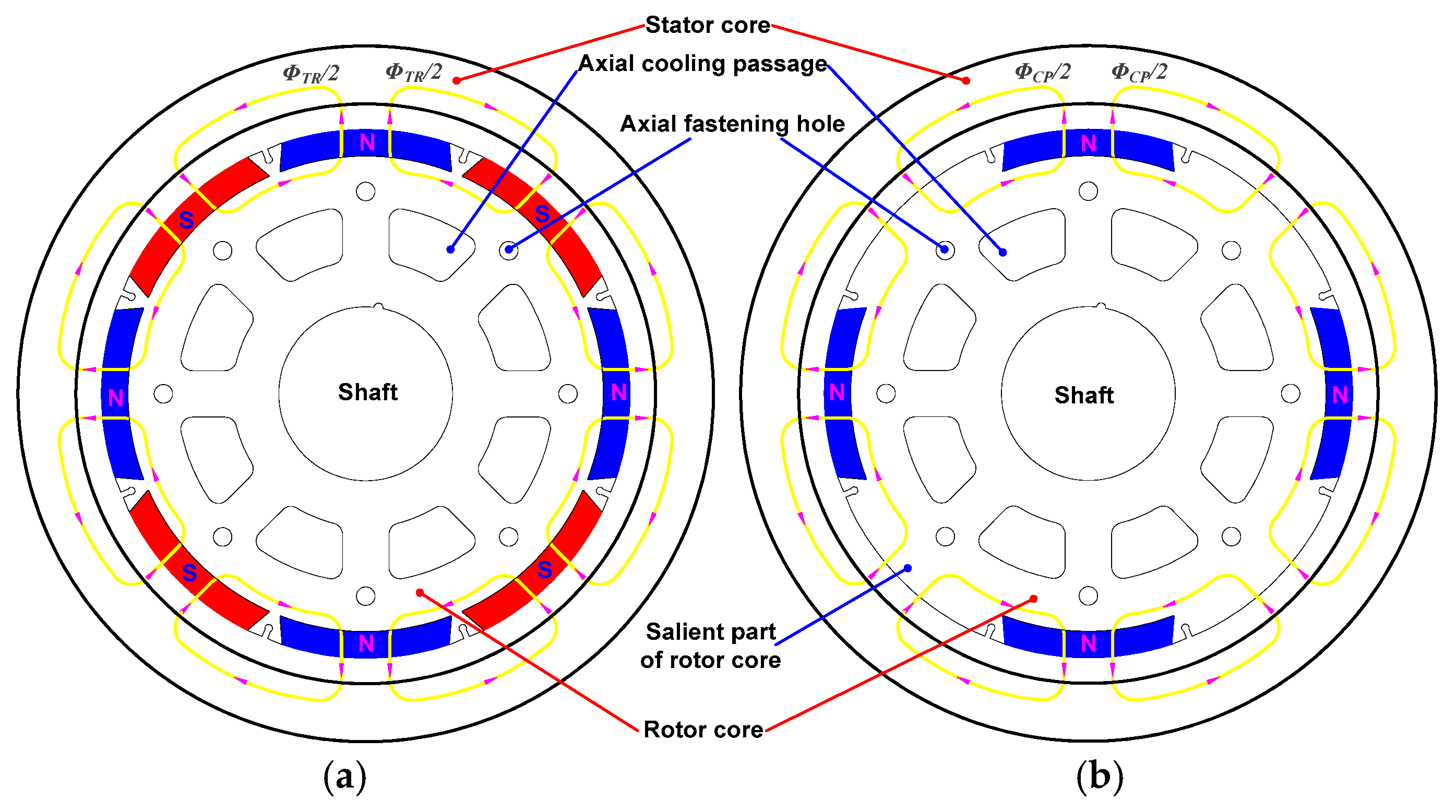
Figure 3 compares the magnetic circuits of the main flux for the conventional PM machine and the CPPM machine. The stator cogging structure is neglected in the figure. Figure 3a depicts a conventional surface-inserted PM machine. The PMs with alternating magnetization directions are embedded in the circumferential surface of the rotor. The main flux per pole, ΦTR, closes its path through the series connection of the blue-designated N-poles and adjacent red-designated S-poles. Figure 3b illustrates a surface-inserted CPPM machine. This topology utilizes the flux-concentrating characteristic of iron by replacing all S-pole magnets with magnetized salient poles formed by the rotor core. The main flux per pole, ΦCP, closes its path through the series connection of the retained N-poles and adjacent magnetized iron poles.
In the main flux path of a conventional PM machine, a pair of adjacent PMs with opposite magnetization directions are connected in series, leading to the superposition of magnetomotive forces. Neglecting leakage flux, ΦTR can be expressed as:
Φ T R = 2 F 0 2 R g + 2 R m + R s _ T R + R r _ T R
where F0 denotes the magnetomotive force of a single PM; Rg denotes the reluctance of air gap; Rm denotes the reluctance of a single PM; Rs_TR is the reluctance of the stator core in the conventional PM machine; and Rr_TR is the reluctance of the rotor core in the conventional PM machine.
In the main flux path of a CPPM machine, only the magnetomotive force of a single PM is retained. If half of PMs are replaced with iron poles of identical dimensions and leakage flux is neglected, ΦCP can be expressed as
Φ C P = F 0 2 R g + R m + R s a + R s _ C P + R r _ C P
where Rsa denotes the reluctance of iron pole; Rs_CP denotes the reluctance of stator core in a CPPM machine; and Rr_CP denotes the reluctance of rotor core in a CPPM machine (excluding the salient part).
Evidently, Rsa is substantially smaller than Rm. Considering that the saturation level of the iron core in CPPM machines tends to be lower than that in conventional PM machines, Rs_CP and Rr_CP are also smaller than Rs_TR and Rr_TR, respectively. By comparing Equations (10) and (11), it is evident that when the PM material consumption is reduced by 50%, the loss ratio of the total flux per pole will inevitably be less than 50%, and the loss ratio of the machine output capability will also be less than 50%. Consequently, the torque produced per unit volume of PM material will inevitably increase, thus improving the utilization of the PM material.
To achieve or approach the power density of conventional PM machines, parameter optimization of the CPPM machine is required. Figure 4 illustrates the magnetic circuit diagram of ΦCP. In the figure, Rgm denotes the reluctance of the air gap adjacent to PM; Rgi denotes the reluctance of the air gap adjacent to iron pole; F = F0RmΦ represents the magnetomotive force supplied by the PM within the magnetic circuit; F0 = RmΦ0; Φ0 = BrSm; and Sm is the cross-sectional area of PMs.
The reluctance of a single PM can be expressed as
R m = 2 h m μ 0 L a D r o θ m
where θm denotes the active surface angle of tile-shaped PM.
The reluctance of the air gap adjacent to PM can be expressed as
R g m = 2 g ξ μ 0 L a D g θ m
where g denotes the air gap length; Dg represents the diameter at the air gap midline; and ξ corresponds to the slot opening factor.
The reluctance of the air gap adjacent to iron pole can be expressed as
R g i = 2 g ζ μ 0 L a D g θ i
where θi corresponds to the active surface angle of iron pole.
By neglecting leakage flux and core reluctance, and substituting Equations (12)–(14) into Equation (11), the expression for the main flux in the CPPM machine can be derived as follows:
Φ C P = ( 1 ξ ) h m D g θ i ( 1 ξ ) h m D g θ i + g D r o θ i + g D r o θ m B r L D r o 2 θ m
The expression for the main flux in conventional PM machines is given by:
Φ T R = ( 1 ξ ) h m D g ( 1 ξ ) h m D g + g D r o B r L D r o 2 θ m

4. Performance Analysis and Optimal Design

4.1. Sensitivity Analysis of Machine Parameters

Based on the dual considerations of maximizing component commonality and avoiding increased manufacturing complexity, this study selects only the PM thickness hm and PM active surface angle θm as key parameters for sensitivity analysis in the optimization process of the CPPM machine.
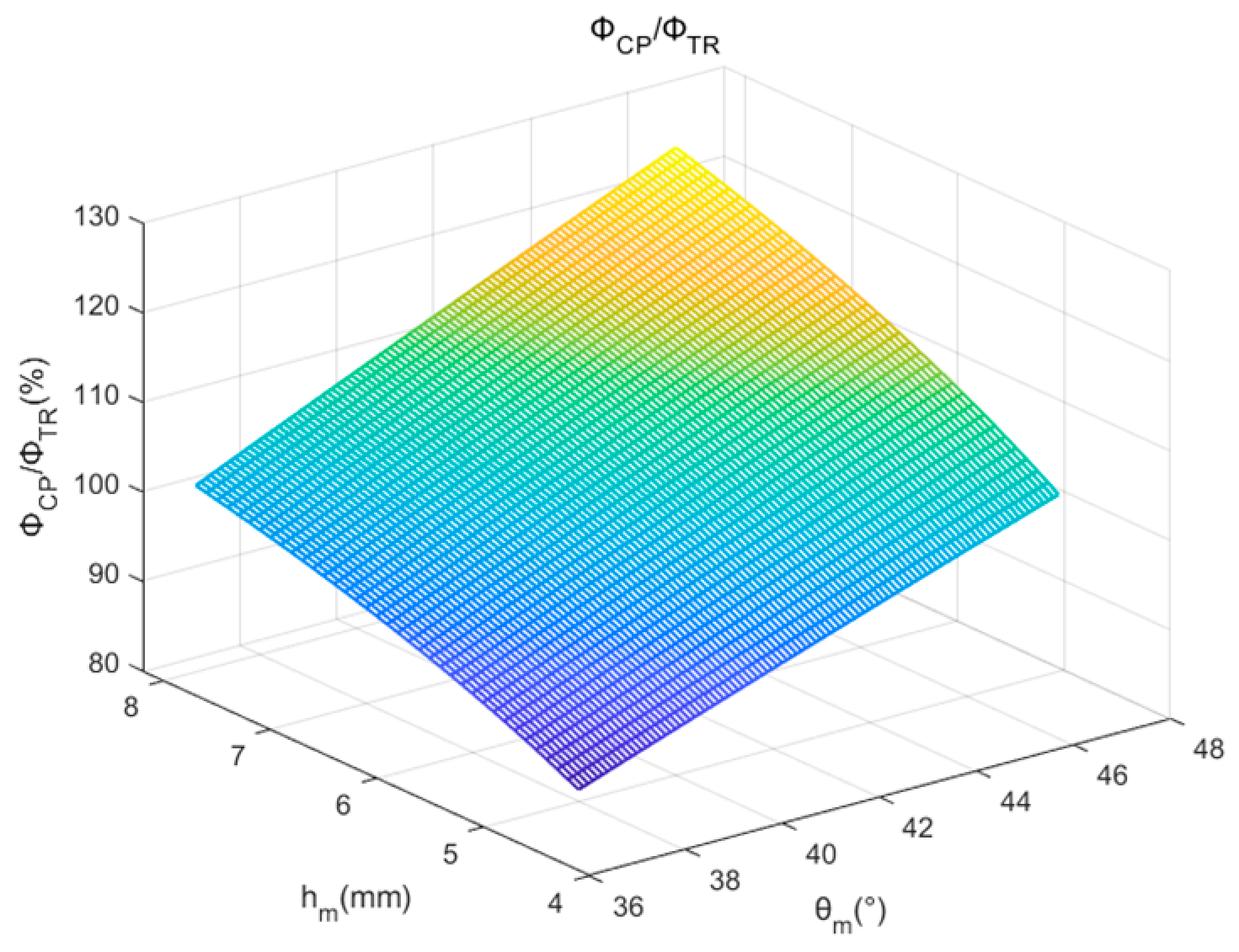
Figure 5 illustrates the variation of ΦCPTR with different combinations of hm and θm. When ΦCPTR equals 1, the total magnetic flux of the CPPM machine reaches that of the benchmark machine. From the data in the figure, it can be observed that for a fixed value of hm, ΦCPTR increases monotonically with the increase of θm; similarly, for a fixed value of θm, ΦCPTR increases monotonically with the increase of hm.
The blue data points in Figure 6 illustrate the combinations of hm and θm when ΦCPTR = 1. The data indicate that a trade-off between hm and θm is required. The PMs must adopt either a “thin-yet-wide” or a “narrow-yet-thick” shape.
The red data points in Figure 6 show the ratio VCP/VTR of the PM material volume consumed by the CPPM machine to that of the benchmark machine for different values of hm when ΦCPTR = 1. The data demonstrate that selecting a “thin-yet-wide” magnet shape is beneficial for saving PM material.
An excessively thin PM results in extremely high mechanical brittleness, making it prone to damage. Conversely, an excessively thick PM increases the complexity of the sintering process, easily leading to internal defects, and presents significant challenges for magnetization. Therefore, in the subsequent optimization process of the PMs in this paper, parameter hm is maintained identical to that of the benchmark machine’s PM, and ΦCP is improved solely by increasing the working surface angle θm.

4.2. Direct Conversion of Conventional to CP Topologies

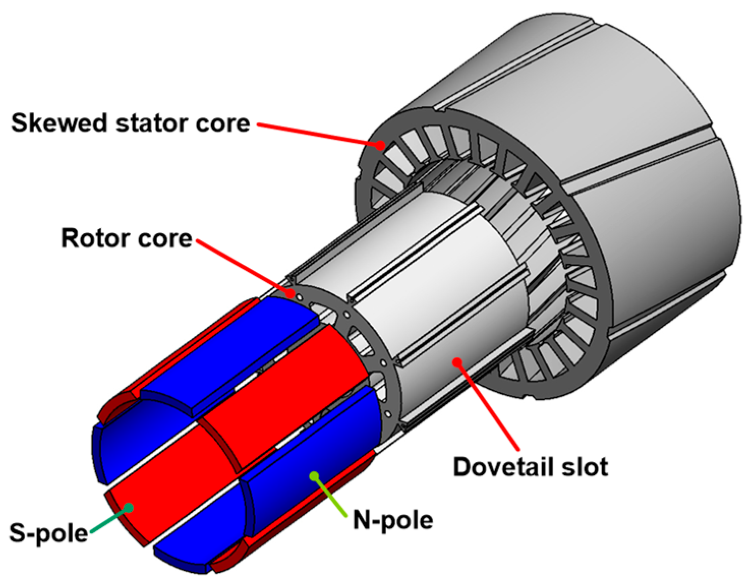
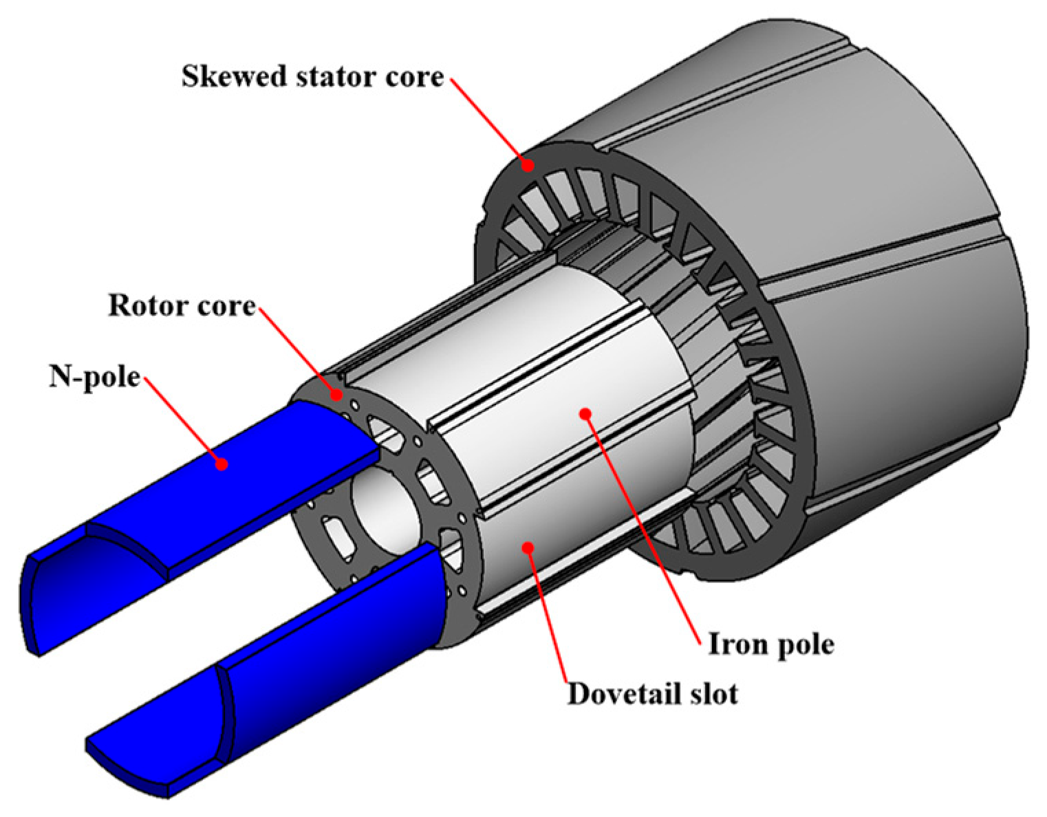
Table 1 lists the main parameters of a conventional surface-inserted REPM machine driven by square-wave current. The geometric model of this design is illustrated in Figure 7. The stator core of this design adopts skewed slots with a 15-degree mechanical skew angle. Eight tile-shaped PMs are inserted into equally spaced dovetail slots on the rotor surface. The three-phase stator windings employ full-pitch coils. To avoid obscuring the display of stator skewed slots, the windings are omitted in the model.
By replacing all PM material in the N-pole regions of this design with the same soft-magnetic material used in the rotor core while retaining all other design details, the primitive CPPM machine configuration is formed. This CPPM topology achieves a 50% reduction in PM material consumption—measured both by the number of pieces and volume—compared to conventional PM machines.
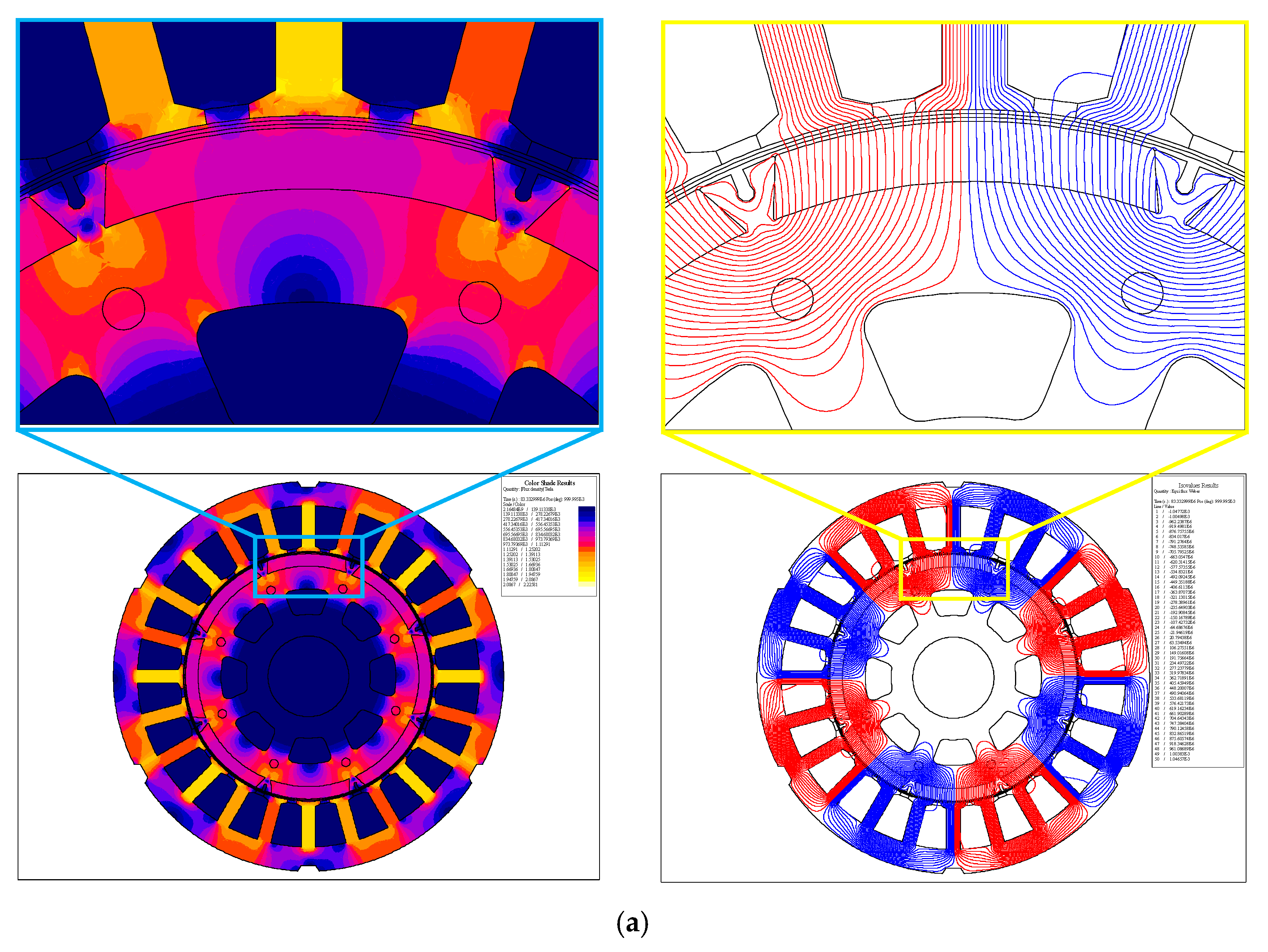
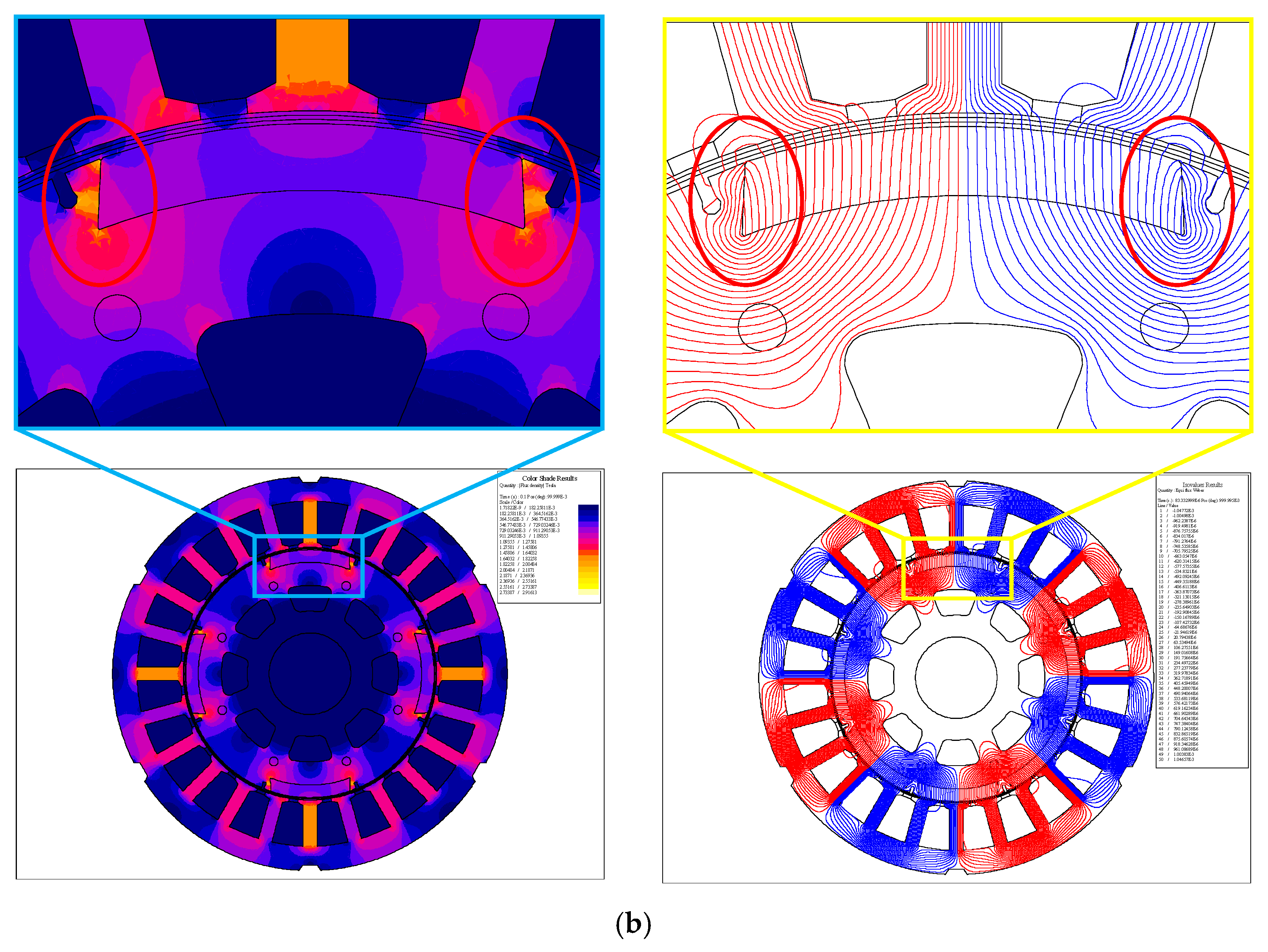
Figure 8 compares the magnetic flux density contours and magnetic flux line distributions of the benchmark machine and the primitive CPPM machine under no-load conditions. The comparison is presented using the aligned position between the magnetic pole centerline and the slot centerline as an example. The primitive design is unoptimized.
Figure 8 reveals that the unoptimized CPPM machine exhibits reduced global magnetic saturation compared to the benchmark machine. However, localized oversaturation regions emerge within its rotor core. The interpolar zones highlighted by red ellipses exhibit excessive magnetic saturation, with localized flux density exceeding 2.4 T. Such localized oversaturation leads to a significant increase in core losses, resulting in overheating hotspots. The edge portions of the PMs embedded within dovetail slots, being in close proximity to these hotspots, are highly susceptible to irreversible demagnetization due to elevated temperatures. Three stator teeth are distributed under each PM pole or iron pole. The tooth aligned with the PM pole centerline demonstrates higher flux density than adjacent teeth, whereas the teeth under the iron poles exhibit comparable flux density values.
The main flux paths are essentially identical in both machines. In the CP configuration, the iron poles replace the S-poles and serve to concentrate the flux. In the conventional PM machine, only a limited amount of leakage flux exists. A portion of the leakage flux closes through the path “N-rotor core (interpolar zone)-S-rotor yoke-N”, while another portion forms closed loop via the paths “N-rotor core (interpolar zone)-N” or “S-rotor core (interpolar zone)-S”. The unoptimized CPPM machine exhibits significant leakage flux issues. The majority of leakage flux forms closed loop through the path “N-rotor core (interpolar zone)-rotor yoke-N”, while a minor portion completes its closed loop via the path “N-air gap-stator teeth-air gap-rotor core (interpolar zone)-rotor yoke-N”.
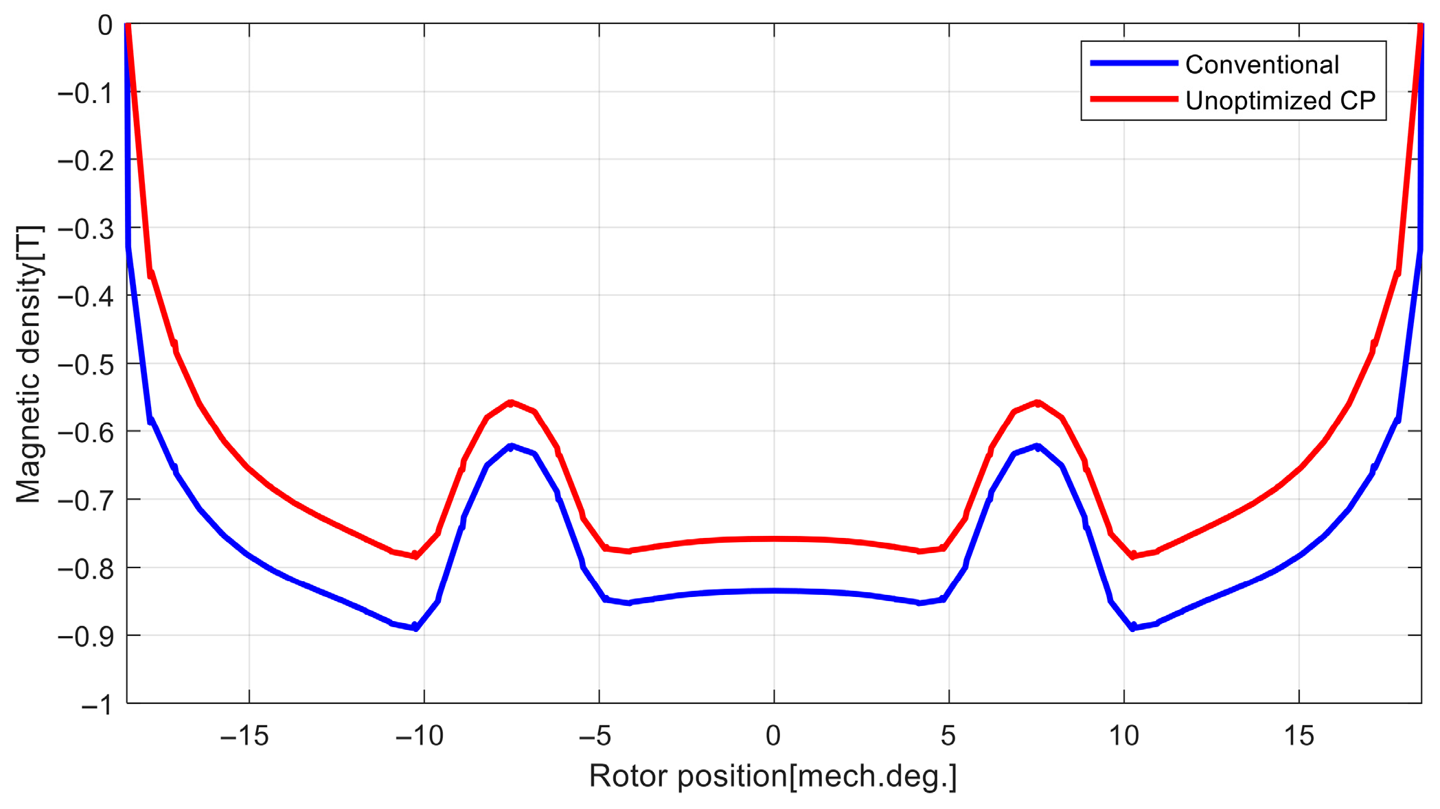
Figure 9 compares the distribution of the normal component of the flux density on the N-pole active surface (the arc surface of the PM pole facing the air gap) between the benchmark and the unoptimized CPPM machine. The waveforms of both distributions are similar. However, at the corresponding rotor position, the flux density value of the unoptimized CPPM machine is significantly lower than that of the benchmark machine. The total flux can be calculated using an integral algorithm.
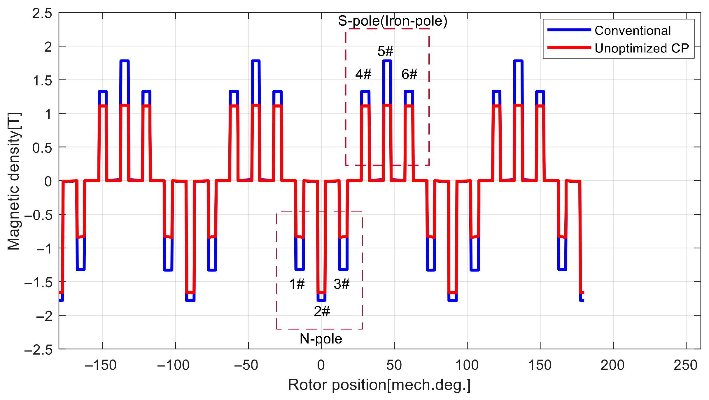
Figure 10 compares the normal flux density distributions along a circular path centered on the machine rotation axis, constructed through the middle of the stator teeth, between the benchmark and the unoptimized CPPM machine. The main flux can be calculated using an integral algorithm. In the benchmark machine, the waveform exhibits near-perfect symmetry between the positive half-cycle (under S-poles) and negative half-cycle (under N-poles). Conversely, the unoptimized CPPM machine demonstrates a visibly asymmetric waveform.
Table 2 lists the magnetic flux density data for the six stator teeth within one pole pair of both the benchmark and the unoptimized CPPM machine, revealing that the flux densities in the corresponding stator teeth of the unoptimized CPPM machine are significantly lower than those in the benchmark. Under the N-pole, the flux density in Tooth 2# (where the tooth centerline is aligned with the PM pole centerline) approaches that of the benchmark, reaching 93.32% of its value, while the other two teeth reach only 62.78%. Under the iron pole, the flux densities in the three stator teeth are essentially equal.; however, the flux density in Tooth 5# (where the tooth centerline is aligned with the iron pole centerline) reaches only 63.16% of the value in the benchmark, whereas the other two teeth reach 83.71%.
Table 3 presents the magnetic flux data for the benchmark and the unoptimized CPPM machine. Compared with the benchmark, the unoptimized CPPM machine exhibits a 13.48% reduction in total flux and a 24.79% decrease in main flux while utilizing 50% less PM material. This indicates that CP configuration can substantially enhance PM material utilization efficiency. However, the tabulated data reveal that the leakage flux increases by over 9 times, demonstrating significant flux leakage issue and consequently low flux utilization ratio.
Figure 11 compares the no-load back-EMF of three-phase windings in the benchmark and unoptimized CPPM machines at rated speed. Both machines exhibit smooth trapezoidal profiles with flat-top widths below 120-degree electric angle and demonstrate identical phase alignment across corresponding phases. However, the back-EMF amplitude of the unoptimized CPPM machine is significantly lower. Harmonic analysis reveals exclusively odd-order components in both cases, indicating perfect half-wave symmetry in the back-EMF waveforms. Crucially, waveform distortion and even-order harmonics—frequently reported in literature for CPPM machines—are absent in the configuration investigated in this study.
Table 4 lists output capability data for the benchmark machine and the unoptimized CPPM machine. The data indicate that, compared to the benchmark, the back-EMF coefficient at rated speed decreases by 21.55%, the electromagnetic torque at rated current reduces by 20.93%, while the electromagnetic torque per unit volume of PM material increases by 58.19%. Analysis of the data reveals a significant improvement in the utilization efficiency of the PM material. However, the unoptimized CPPM machine also exhibits lower torque density.

4.3. Performance-Oriented Optimization Targeting Total Flux Enhancement

In conventional PM machines, the pole-arc coefficients for both the N-pole and S-pole are generally equal and cannot exceed 1. Conversely, in CPPM machines, the pole arc coefficient of the PM poles can exceed 1, offering greater design flexibility. Therefore, the subsequent research presented in this paper focuses solely on increasing the active surface angle of the PM poles in CPPM machines.
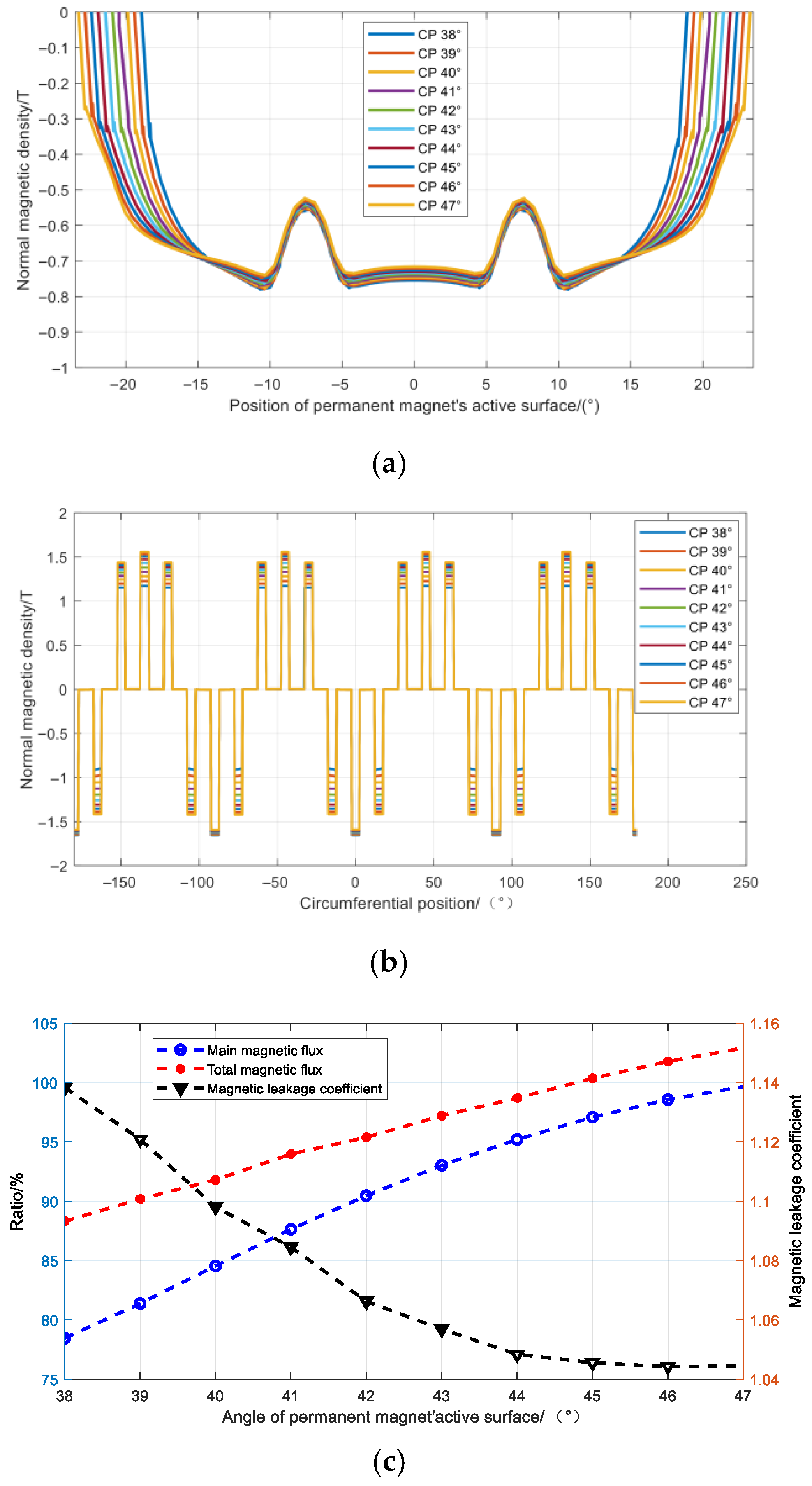
Figure 12 illustrates the influence of the active surface angle variation on the magnetic flux characteristics. Figure 12a compares the distribution of the normal component of magnetic flux density across the active surface corresponding to different active surface angles. The data indicate that as the active surface angle increases, the cross-sectional area of the total flux path increases linearly, while the peak value of the magnetic flux density decreases monotonically, albeit with an extremely slight change. Consequently, increasing the active surface angle within a certain range is effective in increasing the total flux.
Figure 12b compares the distribution of the normal component of magnetic flux density along the circumferential path through the centers of the stator teeth for different active surface angles. The data indicate that as the active surface angle increases, the magnetic flux density in Stator Tooth #2 remains nearly unchanged, while that in the remaining stator teeth increases significantly. However, their saturation levels all remain below that of the benchmark. Consequently, increasing the active surface angle within a certain range is effective in enhancing the main magnetic flux.
Using the benchmark machine data as the base values, Figure 12c illustrates the influence of active surface angle variation on the total flux, main flux, and leakage coefficient of the CPPM machine. The data indicate that as the angle increases: (1) Both the total flux and main flux exhibit an approximately linear increasing trend, with the main flux increasing more rapidly; (2) The leakage coefficient exhibits a monotonically decreasing trend. When the angle increases within the range of 38° to 45°, the leakage coefficient decreases rapidly. Beyond 45°, the leakage coefficient changes minimally. To avoid a significant increase in iron loss caused by excessive saturation, while prioritizing the objective of matching the total flux of the benchmark machine and ensuring reasonable magnetic flux utilization, the optimized active surface angle was selected as 45°. Figure 13 shows the geometric model of the optimized CPPM machine.
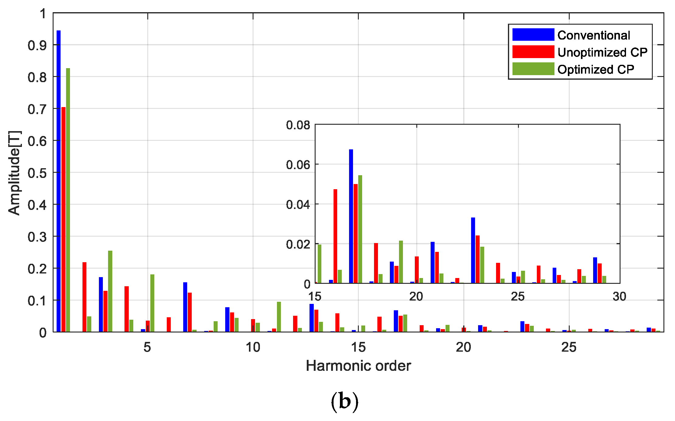
Figure 14 compares the waveforms and harmonic spectra of the no-load air-gap normal flux density for the benchmark machine, the unoptimized CPPM machine, and the optimized CPPM machine. The waveform of the benchmark machine approximates a trapezoidal shape, with its flux density zero-crossing points positioned near the geometric neutral line. The flux density amplitudes under the N-poles and S-poles reach 0.9554 T and 0.9632 T, respectively, exhibiting a difference of less than 1%. Harmonic analysis reveals that the amplitudes of even-order harmonic components are negligible, indicating that the waveform predominantly contains odd-order harmonics. This demonstrates near-perfect symmetry between the waveforms under the N-poles and S-poles.
For the unoptimized CPPM machine, the waveforms under the N-poles and iron poles are visibly asymmetric. The zero-crossing points of the flux density deviate significantly from the geometric neutral line, shifting toward the centerline of the N-poles. Compared with the benchmark machine, the waveform under the N-poles exhibits minimal variation, with an amplitude of 0.8395 T (reaching 87.87% of the benchmark machine’s value). Conversely, the waveform under the iron poles approaches a rectangular shape, featuring a flat-top width of nearly 160 electrical degrees and an amplitude of 0.5315 T (55.18% of the benchmark machine). Harmonic analysis reveals substantial introduction of even-order harmonics, while the fundamental and 3rd-order harmonic amplitudes decrease by 25.47% and 25.08%, respectively, compared with the benchmark machine.
For the optimized CPPM machine, the waveform under the N-poles exhibits minimal variation. Its amplitude measures 0.8014 T, reaching 83.88% of the benchmark machine’s value. Conversely, the waveform under the iron poles approaches a trapezoidal shape, with its flat-top width closely approaching that of the benchmark machine. The amplitude here is 0.7303 T (75.86% of the benchmark machine). The zero-crossing points of the flux density return to the vicinity of the geometric neutral line. Harmonic analysis demonstrates significant suppression of even-order harmonics compared with the unoptimized machine: the 2nd-, 4th-, and 6th-order components are reduced by 77.79%, 73.65%, and 97.82%, respectively. Additionally, symmetry between positive and negative half-cycles shows marked improvement.
Under ideal conditions, the positive and negative half-cycle waveforms of the no-load air-gap flux density in conventional PM machines exhibit perfect symmetry, indicating a balanced magnetic circuit. In CPPM machines, however, iron poles replace a portion of PM poles. When examining solely the air-gap flux density waveform under the iron poles, magnetized iron poles more closely resemble radially magnetized PM poles but demonstrate distinct differences from parallel-magnetized PM poles. In unoptimized CPPM machines, even with identical geometric dimensions between iron poles and the replaced S-poles, substantial even-order harmonic components persist in the air-gap flux density. The flux density waveforms exhibit pronounced asymmetry between positive and negative half-cycles, confirming magnetic circuit imbalance.
Following parameter optimization targeting enhanced total flux in the optimized CPPM machine, even-order harmonics are significantly suppressed though not fully eliminated. The symmetry of positive and negative half-cycle waveforms improves markedly compared to the pre-optimized design, yet the magnetic circuit remains unbalanced. Consequently, magnetic circuit imbalance should be regarded as an inherent characteristic of conventional CPPM machine topologies that is challenging to eliminate, though its degree varies across designs.
An unbalanced magnetic circuit can induce numerous adverse effects, including, but not limited to, unipolar end leakage flux [31]. This end leakage flux can cause unintentional magnetization of components within the end region, thereby posing risks to system safety. This issue becomes particularly pronounced in machines with shorter core stacking lengths or highly saturated magnetic circuits [32]. Consequently, several novel topologies have been proposed to mitigate unipolar end leakage flux. Reference [33] proposed a stepped stagger-pole rotor configuration. Reference [34] proposed two novel rotor pole arrangements characterized by the sequences “N-iron-N-iron-N-S-iron-S-iron-S” and “iron-S-iron-S-iron-iron-N-iron-N-iron”, with embedded tangentially magnetized PMs. Reference [35] proposed a novel rotor pole arrangement characterized by the “N-S-iron-S-N” sequence, incorporating flux barriers to improve the spatial symmetry of the air-gap flux distribution. The novel topologies effectively suppress (or even entirely eliminate) unipolar end leakage flux.
However, they often introduce machining difficulties, posing challenges to manufacturing processes. Multiple publications by Professor Z. Q. Zhu’s research team indicate that employing either a non-magnetic shaft or an inner non-magnetic ring within the rotor core effectively suppresses unipolar end leakage flux [36,37]. Specifically, utilizing the non-magnetic shaft alone achieves a 90% reduction in this leakage flux. Implementation of solely the inner non-magnetic ring yields a 40% reduction. Notably, the combined implementation of both features attains a 95% reduction in unipolar end leakage flux [5]. This solution offers simplicity and effectiveness while avoiding the manufacturing complexity of the novel topologies. Following the strong recommendation in [5], a non-magnetic shaft was adopted in this work.
The rotor shaft of the benchmark is fabricated from medium-carbon alloy structural steel 40Cr. This material offers advantages such as high strength, high hardness, good wear resistance, excellent fatigue strength, and relatively low cost, making it a common choice for rotor shafts. However, 40Cr is a ferromagnetic material and is thus susceptible to magnetization. To increase the reluctance of the magnetic circuit and thereby mitigate unipolar end leakage flux, this study’s optimized CPPM machine employs a rotor shaft made of the non-magnetic austenitic stainless steel 304.
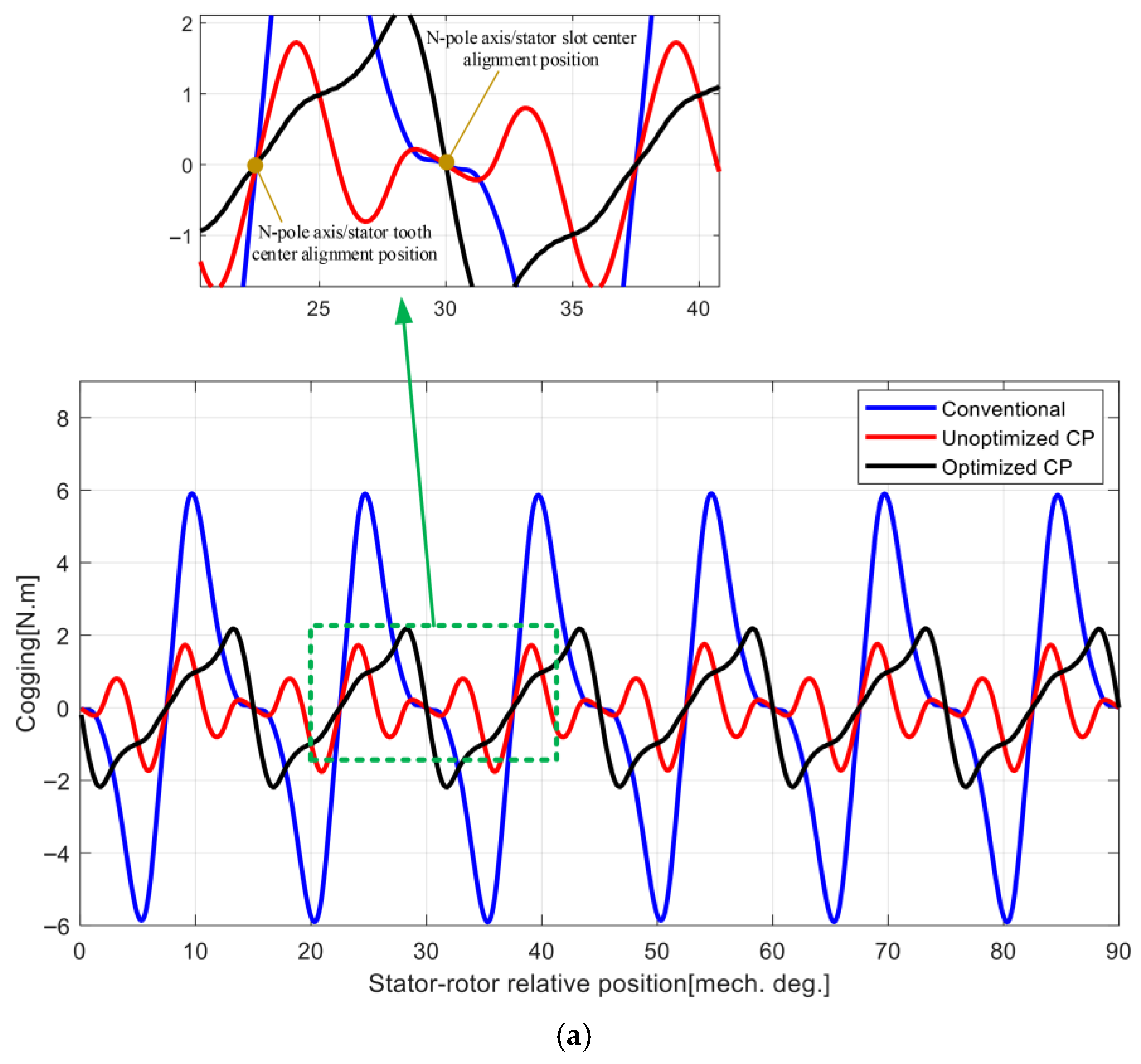
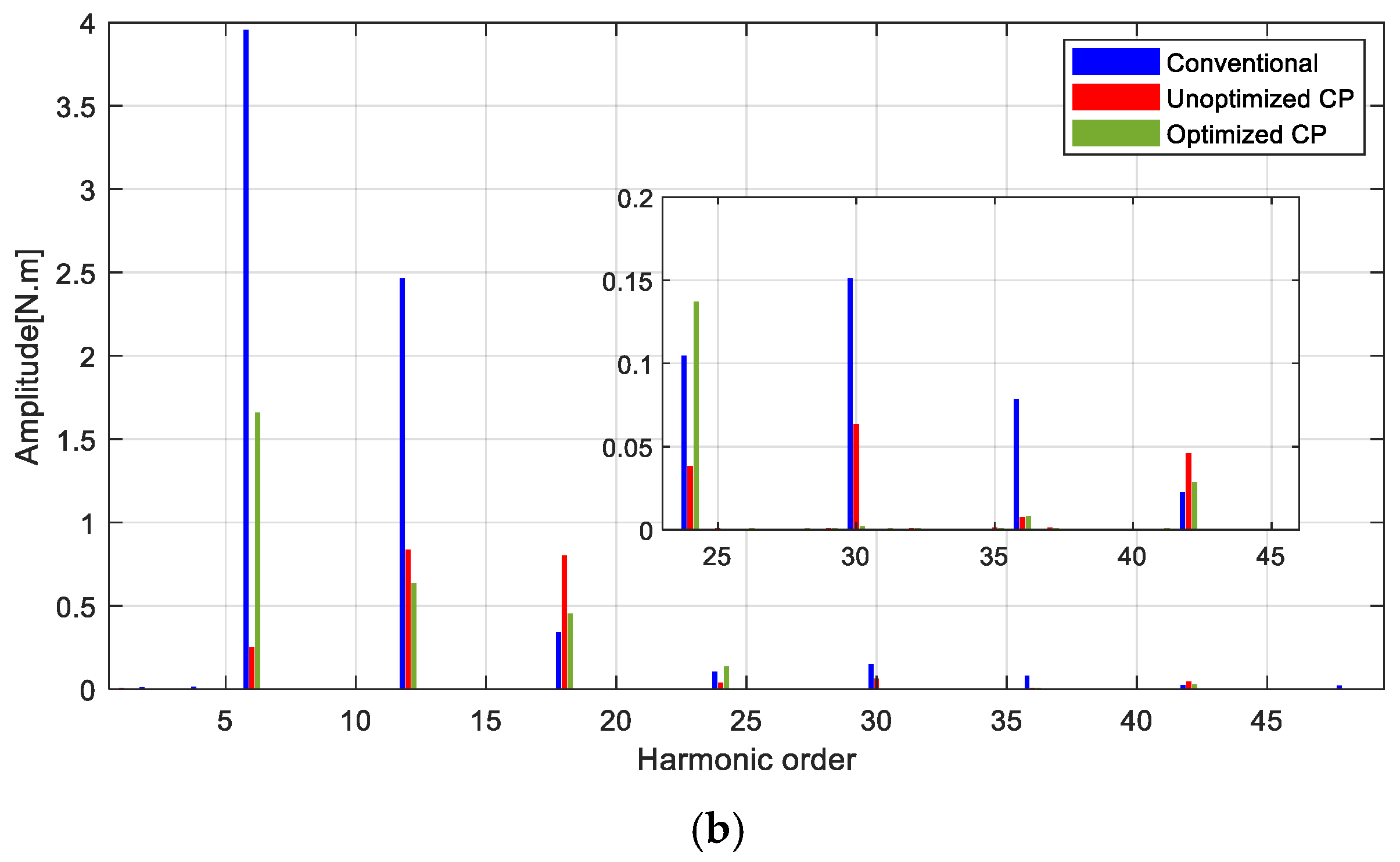
Figure 15 compares the cogging torque of the benchmark machine, the unoptimized CPPM machine, and the optimized CPPM machine. Only one full electrical cycle (equivalent to 6 tooth pitch angles) of cogging torque is displayed. Both the unoptimized and optimized CPPM machines exhibit significantly lower cogging torque amplitudes than the benchmark machine, reaching only 29.75% and 37.05% of its magnitude, respectively. The cogging torque reaches zero when the centerline of an N-pole coincides with either a tooth centerline or a slot centerline. Harmonic analysis reveals that the cogging torque of all three machines consists exclusively of the 6th-order harmonics and their integer multiples. This indicates that the studied 24-slot/8-pole CPPM machines exhibit the same cogging torque periodicity (one tooth pitch angle) as the benchmark machine. This validates the aforementioned analytical conclusion regarding the cogging torque characteristics of CPPM machines. Based on these findings, the stator core design of the benchmark machine was directly adopted for the optimized CPPM machine.
Figure 16 presents the no-load back-EMF of the three-phase windings for the optimized CPPM machine. Compared to the initial design, the amplitude exhibits a significant increase; the width of the flat-top region more closely approaches 120 electrical degrees; and the flatness within this region improves. Harmonic analysis reveals that the amplitudes of the even-order harmonic components are negligible, demonstrating near-perfect symmetry between the positive and negative half-cycles of the waveform.
Table 5 lists key magnetic flux and output capability data for the optimized CPPM machine. Compared to the pre-optimization state, the PM material consumption increased by 20.32%. The total flux and main flux increased by 15.97% and 29.09%, respectively. The back-EMF coefficient increased by 16.92%, and the torque increased by 11.54%. Conversely, the leakage flux decreased by 64.26%, and the leakage coefficient decreased by 10.16%. The torque per unit volume of PM material decreased by 7.30%. Crucially, compared to the benchmark machine, the optimized CPPM machine achieves 88.19% of the benchmark’s torque while consuming only 60.16% of the PM material.
The raw materials for rare-earth permanent magnet motors include rare-earth permanent magnets, electrical steels, magnet wires, and aluminum alloys, among others. A comparative analysis of the mass data for the primary raw materials used in the benchmark motor and the optimized consequent-pole permanent magnet motor is provided in Table 6. Based on the Chinese Yuan (CNY) as the valuation currency and estimated according to real-time market prices (as of 11 September 2025), a comparison of the cost data for the main raw materials of the two motor designs is presented in Table 7. The total material cost of the optimized consequent-pole permanent magnet motor reaches 86.28% of that of the benchmark motor. Considering the achieved torque ratio (88.19%), the outcome of this consequent-pole modification demonstrates limited effectiveness when evaluated solely from the perspective of reducing the total raw material cost. However, the cost of rare-earth permanent magnets accounts for 36.22% of the total raw material cost in the benchmark motor, while it constitutes only 25.28% in the optimized consequent-pole permanent magnet motor. This indicates a significant reduction in the proportion of raw material cost attributable to rare-earth permanent magnets after the consequent-pole modification. Should the unit price of rare-earth permanent magnets experience a substantially sharper increase compared to that of other raw materials, the cost advantage of the consequent-pole permanent magnet motor in terms of raw material expenses will become more pronounced.

5. Experimental Validation

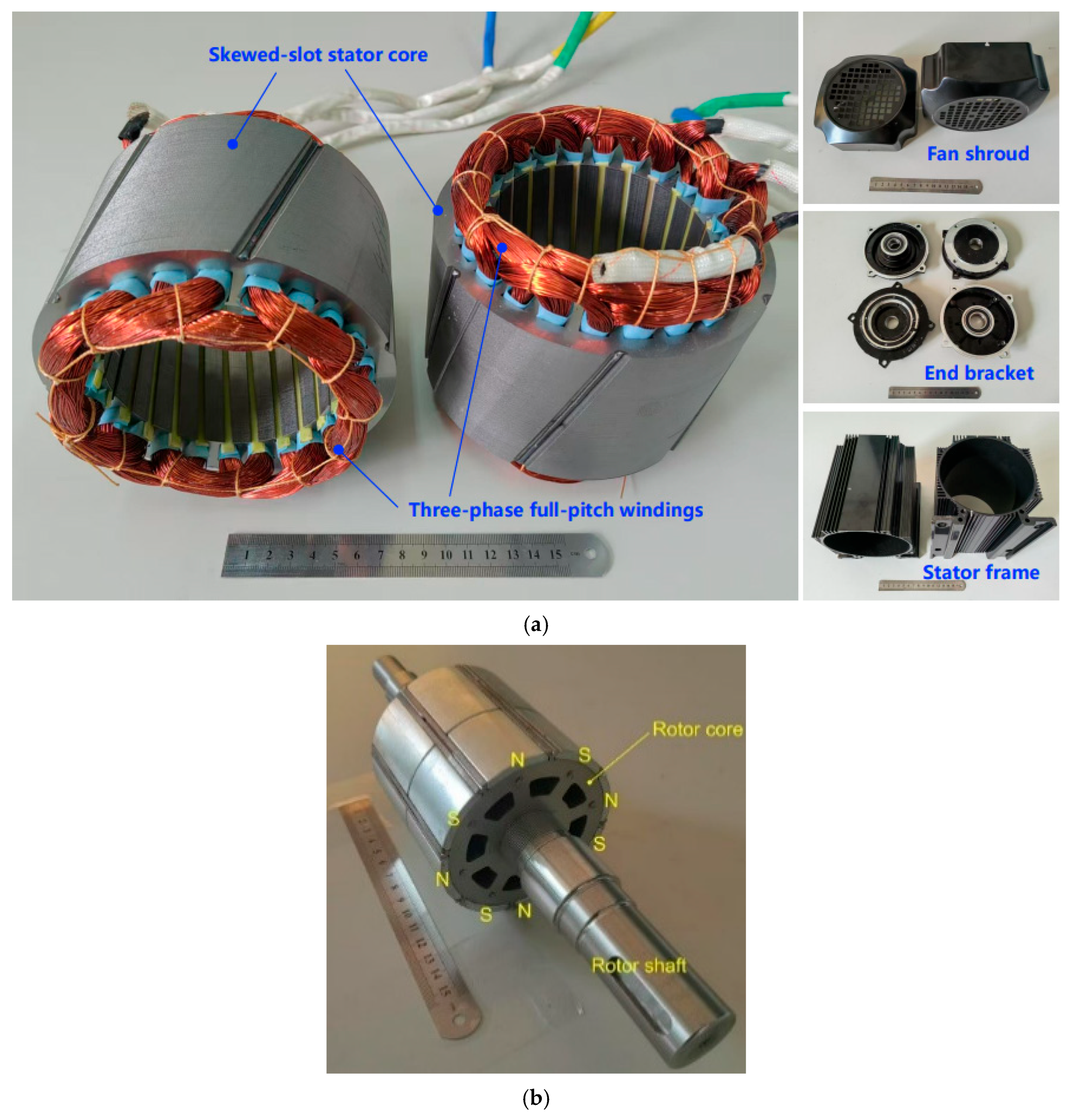
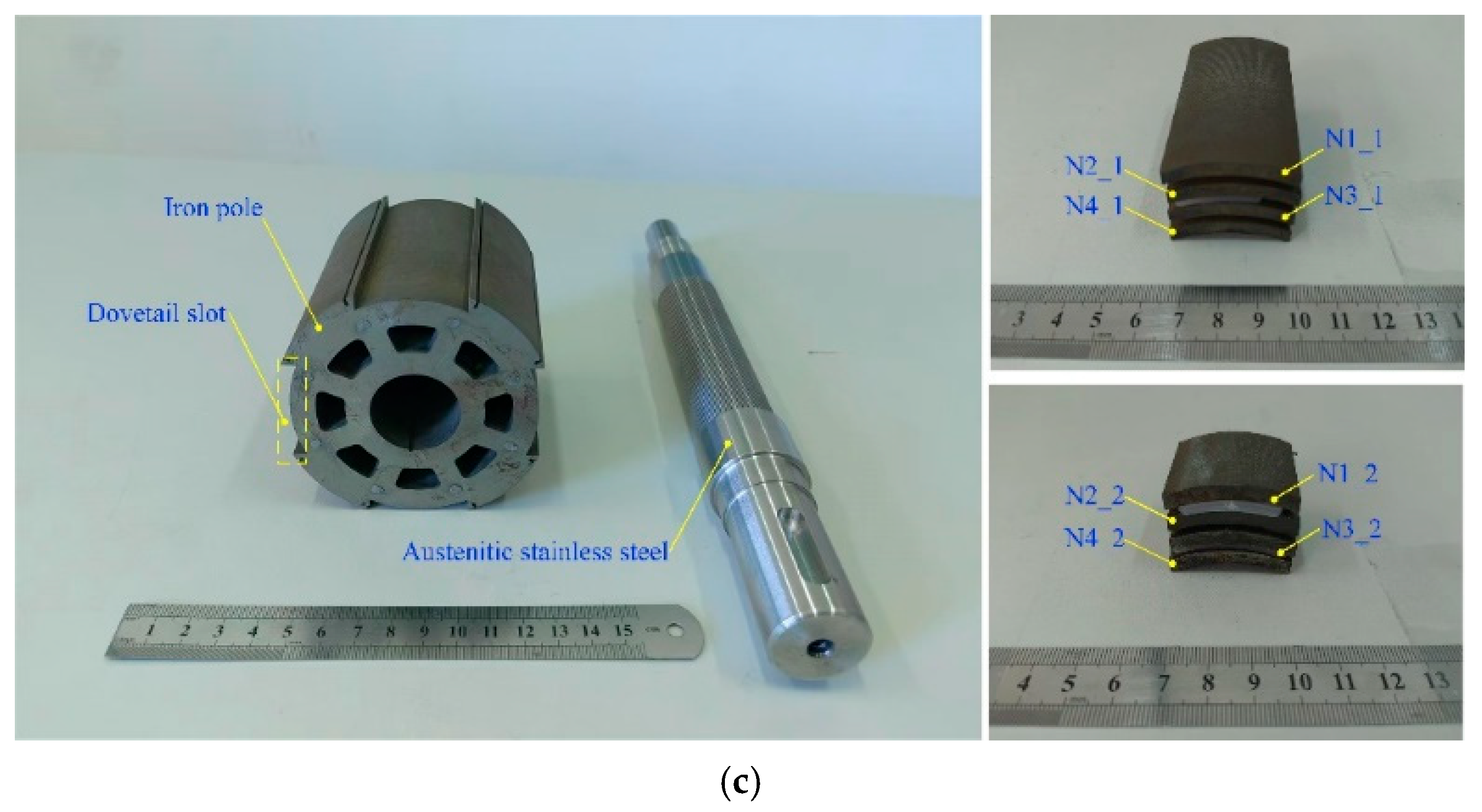
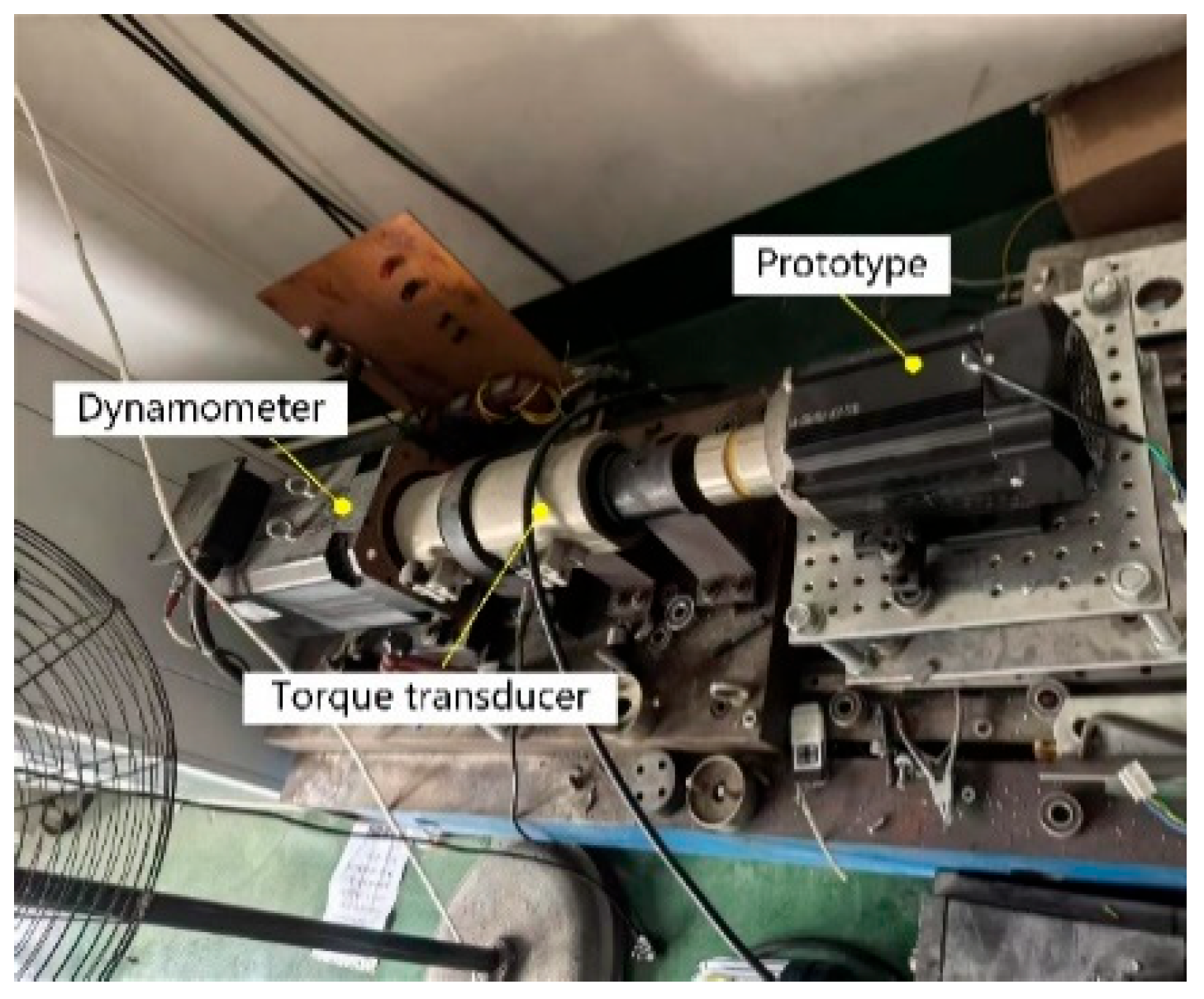
To validate the effectiveness of the finite element model, prototype machines—comprising a benchmark design and an optimized CPPM design—were fabricated. Figure 17 displays the stator and rotor assemblies of these prototypes. Both prototypes share identical stator components, while their rotor configurations differ. Figure 18 illustrates the experimental test platform.
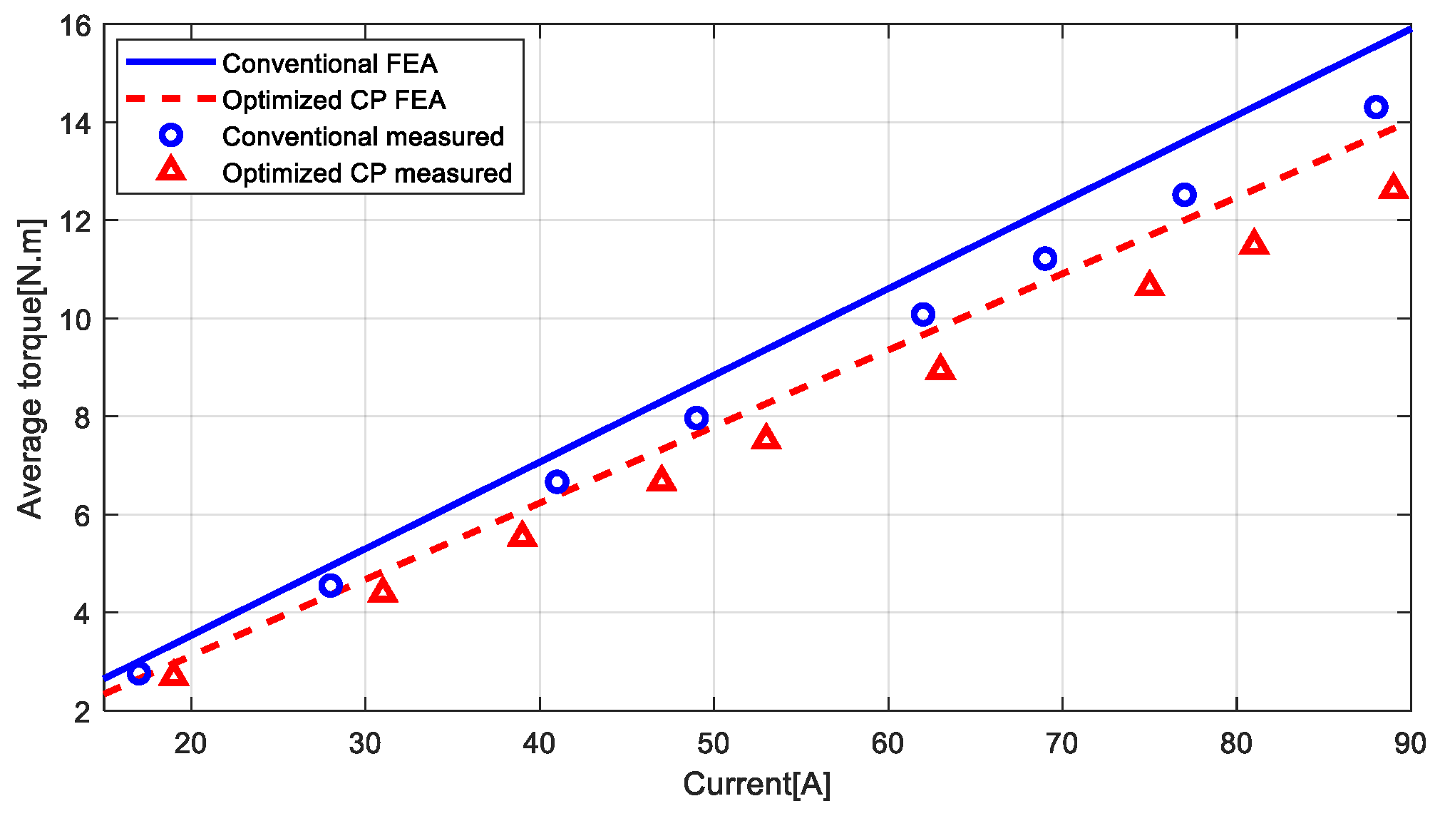
A comparison between the finite element-predicted and experimentally measured average torque data is presented in Figure 19. It should be noted that the finite element model was constructed using the prototype’s actual axial length and room-temperature (20 °C) conditions. The core stacking factor was estimated at 0.95. The model, developed with Altair Flux’s Skew module, does not account for end-winding effects or mechanical tolerances. Additionally, the operational temperature during prototype testing exceeded room temperature. Consequently, acceptable deviations between the finite element predictions and experimental measurements are observed. Nevertheless, overall consistency between the simulated and experimental results remains satisfactory, thereby confirming the validity of the theoretical analysis.
Inevitable discrepancies exist between the simulation results and experimental data. These errors may originate from the following four sources: (a) modeling errors due to idealizations and simplifications in the simulation model; (b) manufacturing and assembly variations introduced during fabrication; (c) experimental uncertainties caused by measurement system errors; and (d) computational inaccuracies arising from the inherent limitations of numerical methods.

6. Conclusions

Focusing on the prevalent challenges of high torque ripple and low torque density in CPPM machines, this study prioritizes cogging torque characteristics and optimization methodologies. Key findings reveal that: (1) the number of complete cogging torque cycles over 360 mechanical degrees equals the least common multiple of the stator slot count Ns and pole pairs p; (2) for CPPM machines derived directly from conventional surface-inserted topologies, increasing the active surface angle of PMs within a feasible range simultaneously enhances total flux while reducing leakage flux, thereby improving average output torque; and (3) even without any dedicated optimization, skewed surface-inserted CPPM machines with full-pitch windings exhibit near-perfect half-wave symmetry in no-load back-EMF waveforms, with no presence of even-order harmonics in spectral components.
It should be noted, however, that this study exhibits several limitations: (1) the optimization solely targeted the active surface angle of PMs, leaving room for further enhancement; while the total flux achieves parity with the benchmark machine, its distribution demonstrates flattening—particularly pronounced beneath the iron poles; (2) radial leakage flux is substantially reduced compared to the pre-optimized design yet retains further optimization potential; and (3) adverse effects of harmonic magnetic fields are neglected, resulting in elevated spatial harmonic content with notably amplified amplitudes of third- and fifth-order harmonics.
Building upon the aforementioned limitations, future research could prioritize the following directions: (1) implementing Halbach arrays or similar flux-focusing structures to direct magnetic flux toward regions most effective for stator interaction; (2) introducing magnetic barriers to further suppress radial leakage flux; and (3) conducting predictive modeling and optimization of losses and noise, vibration, and harshness performance.
Prototype measurements demonstrate technically sufficient consistency with finite element predictions, validating the efficacy of the finite element model and the soundness of the theoretical framework. The findings herein provide valuable references for mechanistic investigations and optimization design of CPPM machines.

Author Contributions

Conceptualization, J.L. and Z.F.; methodology, L.W. and M.S.S.; software, Q.W.; validation, L.W. and Q.W.; formal analysis, investigation, resources, data curation, X.W.; writing—original draft preparation, writing—review and editing, L.W. and M.S.S.; visualization, supervision, project administration, funding acquisition, Z.F. All authors have read and agreed to the published version of the manuscript.

Funding

This research was funded by Natural Science Foundation of China, grant number 52477063.

Data Availability Statement

The original contributions presented in this study are included in the article. Further inquiries can be directed to the corresponding author.

Acknowledgments

During the preparation of this manuscript/study, the authors used Altair Flux for the purposes of finite element calculation. The authors have reviewed and edited the output and take full responsibility for the content of this publication.

Conflicts of Interest

Author Qi Wang was employed by Altair Engineering Software (Shanghai) Co., Ltd. The remaining authors declare that the research was conducted in the absence of any commercial or financial relationships that could be construed as a potential conflict of interest.

Abbreviations

The following abbreviations are used in this manuscript:
CPPMConsequent-pole permanent magnet
CPConsequent-pole
PMPermanent magnet
REPMRare earth permanent magnet
NdFeBNeodymium Iron Boron
SmCoSamarium Cobalt
LCMLeast common multiple
EMFElectromotive force

References

  1. Li, Y.; Yang, H.; Lin, H.; Qin, L.; Lyu, S. Investigation of Double-Side Field Modulation Mechanism in Consequent-Pole PM Machines with Concentrated Windings. IEEE Trans. Energy Convers. 2021, 36, 1635–1648. [Google Scholar] [CrossRef]
  2. Hsieh, M.-F.; Chang, C.-Y.; Huynh, T.-A.; Dorrell, D.G. Design and Analysis of Consequent-Pole Permanent Magnet Vernier Motor with Cancellation of Even-Order Harmonics. IEEE Trans. Magn. 2023, 59, 8204406. [Google Scholar] [CrossRef]
  3. Wang, Z.; Dai, B.; Guo, Z.; Yang, J. Single-Loop Current-Constrained Speed Regulation for PMSM via a Switching Controller. IEEE Trans. Transp. Electrif. 2025, 11, 5974–5982. [Google Scholar] [CrossRef]
  4. Dai, B.; Wang, Z.; Zhao, J.; Li, S. Critical Current-Constrained Continuous Nonsingular Terminal Sliding Mode Control for PMSM Based on Control Barrier Function. IEEE Trans. Power Electron. 2025, 40, 15093–15103. [Google Scholar] [CrossRef]
  5. Zheng, Y.; Zhu, Z.Q.; Liang, D.; Xu, H.; Zhou, Y.; Liu, H. Analysis and Reduction of Unipolar End Leakage Flux in Consequent-Pole PM Machines. IEEE Trans. Ind. Appl. 2025, 61, 196–208. [Google Scholar] [CrossRef]
  6. Dajaku, G. Comparison Study of Permanent Magnet Synchronous Machines with Consequent Pole and HUPM Rotor. IEEE Trans. Magn. 2022, 58, 8104110. [Google Scholar] [CrossRef]
  7. Kumar, R.; Um, D.Y.; Sjöberg, L.; Batra, T.; Atkinson, G. Electromagnetic Analysis and Comparative Study of Surface-Mounted and Consequent Pole Axial Flux Permanent Magnet Machines. IEEE Access 2024, 12, 188926–188939. [Google Scholar] [CrossRef]
  8. Li, Y.; Zhou, Q.; Ding, S.; Hang, J.; Li, W. Quantitative Evaluation of Torque Contributions of Multiple Working Harmonics on Halbach Array Consequent-Pole PM Machine. IEEE/ASME Trans. Mechatron. 2024, 29, 4572–4581. [Google Scholar] [CrossRef]
  9. Li, Y.; Yang, H.; Lin, H.; Zhao, Z. Comparative Study of Field Modulation Effects in Consequent-Pole PM Machines with Different Stator Slot Configurations. IEEE Trans. Magn. 2023, 59, 8103706. [Google Scholar] [CrossRef]
  10. Qi, J.; Zhu, Z.Q.; Yan, L.; Jewell, G.W.; Gan, C.; Ren, Y. Analytical Analysis of Cogging Torque in Permanent Magnet Machines with Unequal North and South Poles, with Particular Reference to Consequent Pole Machines. IEEE Trans. Energy Convers. 2023, 38, 1361–1375. [Google Scholar] [CrossRef]
  11. Chen, B.; Xiao, Y.; Shi, J.; Hu, Y.; Li, L.; Liu, M. Radial Force Characteristics of a Consequent-Pole Permanent Magnet Synchronous Motor. IEEE Trans. Ind. Appl. 2023, 59, 6664–6673. [Google Scholar] [CrossRef]
  12. Hosseinpour, A.; Abbas, A.; Sadegh, M.O.; Iqbal, A.; Flah, A.; Prokop, L. Optimal Structure to Maximize Torque per Volume for the Consequent-Pole PMSM and Investigating the Temperature Effect. IEEE Access 2024, 12, 108851–108862. [Google Scholar] [CrossRef]
  13. Li, F.; Wang, K.; Li, J.; Sun, H.Y. Electromagnetic Performance Analysis of Consequent-Pole PM Machine with Asymmetric Magnetic Pole. IEEE Trans. Magn. 2019, 55, 8103205. [Google Scholar] [CrossRef]
  14. Li, J.; Wang, K.; Zhang, H. Flux-Focusing Permanent Magnet Machines with Modular Consequent-Pole Rotor. IEEE Trans. Ind. Electron. 2020, 67, 3374–3385. [Google Scholar] [CrossRef]
  15. Xu, G.; Zhao, W.; Liu, G.; Zhai, F.; Chen, Q. Torque Performance Improvement of Consequent-Pole PM Motors with Hybrid Rotor Configuration. IEEE Trans. Transp. Electrif. 2021, 7, 1561–1572. [Google Scholar] [CrossRef]
  16. Jo, C.; Yun, I.; Hong, H.; Lee, J.; Kim, H. Asymmetric Design of Consequent Pole to Reduce Torque Ripple. IEEE Trans. Magn. 2024, 60, 8204905. [Google Scholar] [CrossRef]
  17. Qi, J.; Zhu, Z.Q.; Yan, L.; Jewell, G.W.; Gan, C.; Ren, Y. Suppression of Torque Ripple for Consequent Pole PM Machine by Asymmetric Pole Shaping Method. IEEE Trans. Ind. Appl. 2022, 58, 3545–3557. [Google Scholar] [CrossRef]
  18. Ullah, W.; Khan, F.; Hussain, S.; Alturise, F.; Yousuf, M.; Akbar, S. Consequences of Flux Gap on Intriguing Features of Modular Stator Inset Permanent Magnet Consequent Pole Synchronous Machine. IEEE Access 2022, 10, 49551–49565. [Google Scholar] [CrossRef]
  19. Hidaka, Y.; Takahashi, S.; Kondo, S.; Iezawa, M. Maintaining Average Torque and Suppressing Torque Ripple with T-Shaped Auxiliary Pole for Spoke Type Multi-Consequent-Pole Motor. IEEE Trans. Energy Convers. 2025, 40, 1400–1410. [Google Scholar] [CrossRef]
  20. Mitsuda, H.; Fukami, T.; Koyama, M.; Ito, K. Investigation of Flux-Modulating Consequent Pole Motors. IEEE Trans. Ind. Appl. 2023, 59, 1648–1658. [Google Scholar] [CrossRef]
  21. Zhou, H.; Tao, W.; Jiang, G.; Li, G.-J.; Liu, G. Reduction of Saturation and Unipolar Leakage Flux in Consequent-Pole PMV Machine. IEEE J. Emerging Sel. Top. Power Electron. 2022, 10, 1870–1880. [Google Scholar] [CrossRef]
  22. Zheng, Y.; Zhu, Z.-Q.; Xu, H.; Yan, J.; Liang, D. Optimal Multi-Tooth Numbers for Vernier PM Synchronous Machines. IEEE Access 2024, 12, 89599–89612. [Google Scholar] [CrossRef]
  23. Zheng, Y.; Xiang, W.; Kang, M.; Wu, L.; Fang, Y. Analysis of Dual PM Vernier Machines with Different Consequent-Pole PM Topologies. IEEE Trans. Ind. Appl. 2023, 59, 1670–1677. [Google Scholar] [CrossRef]
  24. Chen, H.; Zhu, Z.; Zhang, Z.; Wang, H. Comparative Analysis of Consequent-Pole PM Vernier Machines with Different Rotor Types. IEEE Trans. Transp. Electrif. 2024, 10, 450–461. [Google Scholar] [CrossRef]
  25. Liu, W.; Wang, J.; Lipo, T.A. A Consequent Pole Single Rotor Single Stator Vernier Design to Effectively Improve Torque Density of an Industrial PM Drive. IEEE Trans. Ind. Electron. 2023, 70, 255–264. [Google Scholar] [CrossRef]
  26. Ullah, W.; Khan, F.; Hussain, S.; Yousaf, M.; Akbar, S. Analytical Modeling and Optimization of Partitioned Permanent Magnet Consequent Pole Switched Flux Machine with Flux Barrier. IEEE Access 2022, 10, 123905–123919. [Google Scholar] [CrossRef]
  27. Ullah, W.; Khan, F.; Hussain, S.; Yousaf, M.; Akbar, S. Analytical Modeling of Novel High Thrust Force Density Segmented PM Consequent Pole Linear Flux Switching Machine. IEEE Access 2022, 10, 105887–105897. [Google Scholar] [CrossRef]
  28. Rehman, A.; Kim, B. Characteristics Analysis of Consequent-Pole Ferrite Magnet Vernier Machine Using Novel Equivalent Magnetic Circuit. IEEE J. Emerging Sel. Top. Power Electron. 2022, 10, 1823–1833. [Google Scholar] [CrossRef]
  29. Raza Siddiqi, M.; Humza, M.; Yazdan, T.; Hur, J.; Akbar, S. Cost-Effective Design of Dual Airgap Permanent Magnet Vernier Machine Having a Yokeless Consequent Pole Rotor. IEEE Access 2024, 12, 108224–108232. [Google Scholar] [CrossRef]
  30. Xu, L.; Li, Y.; Zhao, W.; Liu, G. Reduction of Unipolar Leakage Flux and Torque Ripple in Consequent-pole PM Vernier Machine. CES Trans. Electr. Mach. Syst. 2023, 7, 35–44. [Google Scholar] [CrossRef]
  31. Zhu, Z.Q.; Hua, H.; Pride, A.; Deodhar, R.; Sasaki, T. Analysis of unipolar leakage flux in series-hybrid permanent magnet Machines. In Proceedings of the 2017 IEEE International Magnetics Conference (INTERMAG), Dublin, Ireland, 24–28 April 2017; pp. 1–2. [Google Scholar]
  32. Li, F.; Wang, K.; Sun, H.Y.; Zhang, H.; Zhang, L. Quantitative Comparison between SPM Machine and Consequent Pole PM Machines with Different Rotor Topologies. In Proceedings of the 2019 IEEE International Electric Machines & Drives Conference (IEMDC), San Diego, CA, USA, 11–15 May 2019; pp. 127–134. [Google Scholar]
  33. Ge, X.; Zhu, Z.Q.; Li, J.; Chen, J. A Spoke-Type IPM Machine with Novel Alternate Airspace Barriers and Reduction of Unipolar Leakage Flux by Step-Staggered Rotor. IEEE Trans. Ind. Appl. 2016, 52, 4789–4797. [Google Scholar] [CrossRef]
  34. Wang, K.; Li, J.; Zhu, S.S.; Liu, C. Novel Hybrid-Pole Rotors for Consequent-Pole PM Machines Without Unipolar Leakage Flux. IEEE Trans. Ind. Electron. 2019, 66, 6811–6823. [Google Scholar] [CrossRef]
  35. Li, J.; Wang, K.; Li, F.; Zhu, S.S.; Liu, C. Elimination of Even-Order Harmonics and Unipolar Leakage Flux in Consequent-Pole PM Machines by Employing N-S-Iron–S-N-Iron Rotor. IEEE Trans. Ind. Electron. 2019, 66, 1736–1747. [Google Scholar] [CrossRef]
  36. Zheng, Y.; Zhu, Z.Q.; Liang, D.; Zhou, Y.; Liu, H.; Chen, L. Analysis and Reduction of Unipolar End Leakage Flux in Consequent-pole Vernier and Fractional Slot PM Machines. In Proceedings of the 2023 IEEE International Electric Machines & Drives Conference (IEMDC), San Francisco, CA, USA, 15–18 May 2023; pp. 1–7. [Google Scholar]
  37. Xu, H.; Zhu, Z.Q.; Zheng, Y.; Zhou, Y.; Chen, L.; Yang, L. Investigation of Unipolar End Flux Leakage in Dual-PM Consequent-Pole Vernier Machines. IEEE Trans. Transp. Electrif. 2025, 11, 2939–2951. [Google Scholar] [CrossRef]
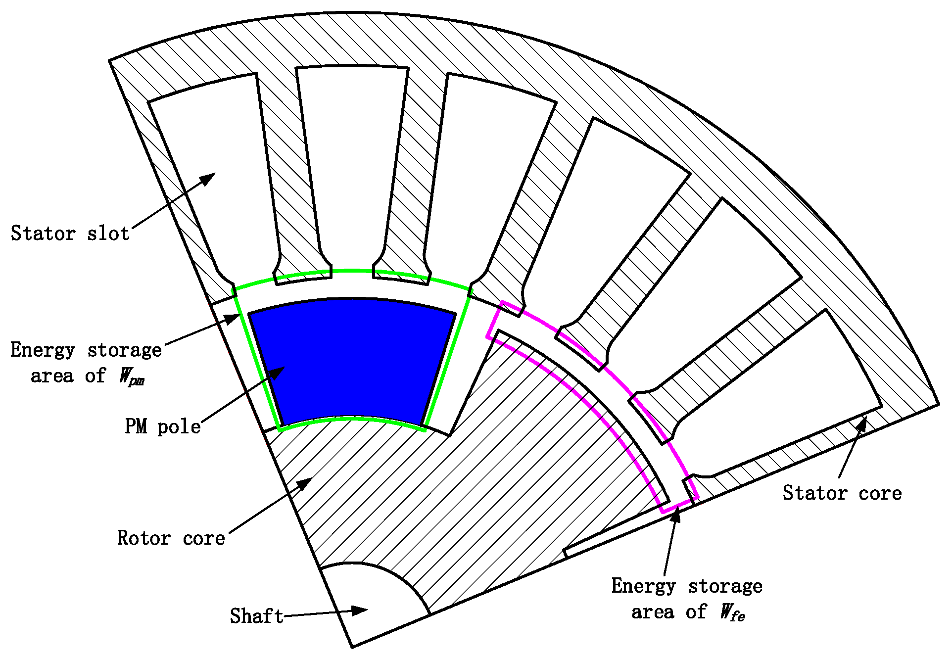
Figure 1. Simplified magnetic field energy distribution region in a CPPM machine.
Machines 13 00873 g001
Figure 2. Circumferential distribution and decomposition of PM remanence in the air gap: (a) Br(θ); (b) Br_pm(θ); (c) Br_fe(θ).
Machines 13 00873 g002
Figure 3. Comparison of the magnetic circuit paths of the main flux between the conventional PM machine and the CPPM machine. (a) conventional surface-inserted PM machine (b) surface-inserted CPPM machine.
Machines 13 00873 g003
Figure 4. Magnetic circuit diagram of ΦCP.
Machines 13 00873 g004
Figure 5. Values of ΦCPTR for different combinations of hm and θm.
Machines 13 00873 g005
Figure 6. Corresponding values of θm and the ratio VCP/VTR of consumed PM material volume versus hm when ΦCPTR = 1.
Machines 13 00873 g006
Figure 7. Geometric model of the benchmark conventional PM machine.
Machines 13 00873 g007
Figure 8. Comparison of magnetic flux density contours and flux line distributions under no-load conditions between the benchmark machine and the unoptimized CPPM machine: (a) Benchmark conventional PM machine; (b) Unoptimized CPPM machine.
Machines 13 00873 g008aMachines 13 00873 g008b
Figure 9. Comparison of normal flux density distributions on the N-pole active surfaces between the benchmark machine and the unoptimized CPPM machine.
Machines 13 00873 g009
Figure 10. Comparison of normal flux density distributions along a circular path centered on the rotation axis through the middle of stator teeth between the benchmark machine and the unoptimized CPPM machine.
Machines 13 00873 g010
Figure 11. Comparison of the no-load back-EMF for the three-phase windings between the benchmark machine and the unoptimized CPPM machine at rated speed: (a) Waveforms; (b) Harmonic spectra.
Machines 13 00873 g011
Figure 12. Influence of the active surface angle variation on the magnetic flux characteristics: (a) Distribution of the normal magnetic flux density across the active surface; (b) Distribution of the normal magnetic flux density along the circumferential path through the centers of the stator teeth; (c) Influence on the total magnetic flux, main magnetic flux, and leakage coefficient.
Machines 13 00873 g012
Figure 13. Geometric model of the optimized CPPM machine.
Machines 13 00873 g013
Figure 14. Comparison of the no-load normal air-gap magnetic flux density among the benchmark machine, unoptimized CPPM machine, and optimized CPPM machine: (a) Waveforms; (b) Harmonic spectra.
Machines 13 00873 g014aMachines 13 00873 g014b
Figure 15. Comparison of cogging torque in the benchmark machine, unoptimized CPPM machine, and optimized CPPM machine: (a) Waveforms; (b) Harmonic spectra.
Machines 13 00873 g015aMachines 13 00873 g015b
Figure 16. No-load back-EMF of three-phase windings in the optimized CPPM machine: (a) Waveforms; (b) Harmonic spectra.
Machines 13 00873 g016
Figure 17. Prototypes: (a) Stator components; (b) Rotor assembly of the benchmark conventional PM machine; (c) Rotor components of the optimized CPPM machine.
Machines 13 00873 g017aMachines 13 00873 g017b
Figure 18. Test bench.
Machines 13 00873 g018
Figure 19. Torque–current characteristics comparison between the benchmark machine and the optimized CPPM machine.
Machines 13 00873 g019
Table 1. Main parameters of the benchmark conventional PM machine design.
ParameterValueParameterValue
Number of stator slots24Active surface angle of PM/(°)37
Number of rotor poles8Slot opening factor0.27
Outer diameter of stator/mm145Number of series conductors per slot4
Outer diameter of rotor/mm91.2Number of strands in parallel96
Length of air gap/mm0.9Number of parallel paths1
Thickness of PM/mm4.6Lamination steel gradeB50A600
Stack length of iron core/mm90PM material gradeN35H
Table 2. Stator tooth flux density data: benchmark vs. unoptimized CPPM machine.
Number of Stator Teeth1#2#3#4#5#6#
Conventional−1.330 T−1.781 T−1.330 T1.326 T1.778 T1.324 T
Unoptimized CP−0.835 T−1.662 T−0.835 T1.110 T1.123 T1.110 T
Table 3. Magnetic flux data: benchmark vs. unoptimized CPPM machine.
StructurePM Material
(mm3)
Total Flux (Wb)Main Flux (Wb)Leakage Flux (Wb)Leakage
Coefficient
Conventional98,5160.0020480.0020250.0000231.0114
Unoptimized CP49,2580.0017720.0015230.0002491.1638
Table 4. Comparison of output capability data between the benchmark machine and the unoptimized CPPM machine.
ParameterBack-EMF Constant
(V·Min·r−1)
Torque (N·m)Torque Per Unit PM Volume
(N·m·mm−3)
Conventional0.0188914.141.435 × 10−4
Unoptimized CP0.0148211.182.270 × 10−4
Table 5. Performance data of the optimized CPPM machine.
ParameterValue
Volume of PM material (mm3)59,270
Total flux (Wb)0.002055
Main flux (Wb)0.001966
Leakage flux (Wb)0.000089
Leakage coefficient1.04555
Back-EMF constant (V·min·r−1)0.01686
Torque (N·m)12.47
Torque per unit PM volume (N·m·mm−3)2.1039 × 10⁻⁴
Table 6. Mass comparison of raw materials between benchmark and optimized CPPM machines.
MaterialSintered NdFeB (kg)Electrical Steel (kg)Magnet Wire (kg)Aluminum Alloy (kg)
Benchmark0.7396.432.213.16
Unoptimized CP0.4457.082.213.16
Table 7. Material cost comparison of raw materials between benchmark and optimized CPPM machines.
MaterialSintered NdFeB
(CNY)
Electrical Steel (CNY)Magnet Wire (CNY)Aluminum Alloy (CNY)Total (CNY)
Benchmark154.4529.26176.8065.91426.42
Unoptimized CP93.0032.21176.8065.91367.92
Disclaimer/Publisher’s Note: The statements, opinions and data contained in all publications are solely those of the individual author(s) and contributor(s) and not of MDPI and/or the editor(s). MDPI and/or the editor(s) disclaim responsibility for any injury to people or property resulting from any ideas, methods, instructions or products referred to in the content.