Article

Remaining Secondary Voltage Mitigation in Multivector Model Predictive Control Schemes for Multiphase Electric Drives

by
Juan Carrillo-Rios
1,
Juan Jose Aciego
1,
Angel Gonzalez-Prieto
2,
Ignacio Gonzalez-Prieto
1,*,
Mario J. Duran
1 and
Rafael Lara-Lopez
1
1
Department of Electrical Engineering, University of Malaga, 29071 Malaga, Spain
2
Department of Electrical Engineering, Polytechnic University of Madrid, 28006 Madrid, Spain
*
Author to whom correspondence should be addressed.
Machines 2025, 13(9), 862; https://doi.org/10.3390/machines13090862
Submission received: 2 August 2025 / Revised: 12 September 2025 / Accepted: 15 September 2025 / Published: 17 September 2025
(This article belongs to the Special Issue Recent Progress in Electrical Machines and Motor Drives)

Abstract

Multiphase electric drives (EDs) offer important advantages for high-demand applications. However, they require appropriate high-performance control strategies. In this context, finite-control-set model predictive control (FCS-MPC) emerges as a promising strategy, offering a notable flexibility to implement multiobjective regulation schemes. When applied to multiphase EDs, standard FCS-MPC exhibits degraded current quality at low and medium control frequencies. Multivector solutions address this issue by properly combining multiple voltage vectors within a single control period to create the so-called virtual voltage vectors (VVVs). In this way, this approach achieves flux and torque regulation while minimizing current injection into the secondary subspace. For this purpose, the VVV synthesis typically prioritizes active vectors with low contribution in secondary subspaces, avoiding the average deception phenomenon. VVV solutions commonly enable an open-loop regulation of secondary currents. Nevertheless, the absence of closed-loop control in the secondary subspace hinders the compensation of nonlinearities, machine asymmetries, and unbalanced conditions in the ED. Considering this scenario, this work implements a multivector FCS-MPC recovering closed-loop control for the secondary subspace. The capability of the proposal to mitigate secondary current injection and compensate for possible dissymmetries is experimentally evaluated in a six-phase ED. Its performance is compared against a benchmark technique in which secondary current regulation is handled in open-loop mode. The proposed control solution significantly improves in current quality, achieving a reduction in harmonic distortion of 54% at medium speed.

1. Introduction

In recent decades, multiphase electric drives (EDs) have progressed from academic research topics and specialized high-power applications to widespread adoption in industrial sectors such as electric vehicles [1,2,3], wind energy conversion systems [4,5], and electric aircraft [6,7]. Compared to conventional three-phase systems, these drives offer several inherent advantages, including higher power density, reduced per-phase power ratings, lower torque ripple, and improved fault tolerance [8,9,10], making them particularly well-suited for high-power and high-reliability applications [11].
Numerous studies aim to fully exploit the capabilities of multiphase EDs [4,10,12]. Typically, these works extend high-performance control schemes originally developed for three-phase EDs. However, the presence of additional degrees of freedom requires significant modifications to effectively leverage the advantages of multiphase machines [8,9,13,14,15,16,17,18]. Some of these approaches develop regulation schemes that utilize an explicit modulation stage to generate gate signals [10,19,20,21,22]. Alternatively, there are control methods with implicit modulation stages, where the control algorithm directly provides the switching signals to the voltage source converter (VSC) [15,23,24,25,26,27]. Among this second variant, finite-control-set model predictive control (FCS-MPC) has attracted significant interest due to its fast dynamic response and extended operating range, resulting from better utilization of the dc-link voltage without requiring any additional overmodulation technique in its standard form [28,29]. As a consequence of its suitable dc-link voltage utilization, FCS-MPC offers improved dynamic performance compared to conventional linear controllers [30]. In addition, FCS-MPC is characterized by an inherent flexibility in incorporating constraints into the cost function to achieve different regulation objectives [31], e.g., reducing switching frequency [32,33], improving current tracking [34] or minimizing the common-mode voltage (CMV) [35]. Despite its advantages, the standard FCS-MPC was overlooked for multiphase EDs due to the relatively high harmonic distortion in stator phase currents [23,29] and a notable computational cost in favor of the industry-established field-oriented control scheme (FOC) [29]. However, the issue related to computational cost can be mitigated by evaluating only a subset of the available control actions [29,36,37]. On the other hand, the problem of high harmonic content in the phase currents stems from the application of a single voltage vector in the standard version of FCS-MPC at low- and medium-control frequencies. Applying a single voltage vector to achieve torque and flux objectives inherently results in the generation of voltage components in the x y subspace, which are associated with Joule losses. This problem becomes considerably more severe in multiphase motors with low stator impedance [23].
Several studies have investigated the mitigation/nullification of harmonics injected into the x y plane through different approaches. Some works have effectively mitigated current injection into the secondary plane using multivector strategies [23,36,37,38,39,40,41,42,43] applying multiple voltage vectors within a single control period. These control actions, known as virtual voltage vectors (VVVs), are designed to minimize average voltage contribution in the x y subspace while achieving control objectives in the main plane. This approach also reduces the computational burden associated with the standard version of FCS-MPC. The number of available vectors and their application times depend on the number of phases in the multiphase ED [37,38,44,45].
In the case of six-phase drives, the initial implementations of multivector strategies in FCS-MPC employed a combination of v L and one medium-large voltage vector to generate the control actions [38,42,46]. The mapping of these vectors presents a favorable arrangement, aligned in the α β plane and oriented in opposite directions within the secondary subspace. This fact enables null average voltage generation in the x y subspace when applied for 73% and 27% of the sampling period, respectively [38]. This solution became a commonly adopted predictive approach in numerous subsequent studies on multivector strategies [24,43,47,48]. However, the use of non-large active vectors to compose the control action may result in average deception [29,43,49], since their notable voltage projection onto the secondary plane gives rise to high instantaneous currents, which are commonly overlooked. Large voltage vectors ( v L ) are commonly employed to generate multivector voltage outputs, because they provide a favorable voltage ratio between the main and secondary subspaces [16,37]. By selecting these v L to generate multivector control actions, the regulation scheme can achieve the desired torque and flux generation while keeping low Joule losses.
Addressing this issue, other multivector proposals in six-phase EDs have enabled the synthesis of control actions using adjacent v L that significantly reduce, or even eliminate, harmonic injection into the secondary plane [36,39]. They enable more efficient usage of the dc link, better dynamic response, and reduced switching frequency, since there is only one change in the switching pattern transition between two adjacent v L [36]. A precise design of control actions that minimize or eliminate harmonic injection into the secondary plane enables the omission of control loops related to this subspace. Consequently, in multiphase drives, two main trends can be identified within multivector strategies: mitigating secondary currents in open-loop schemes thanks to a null average x y production of the control actions, or using a closed-loop approach for the same objective.
Multivector schemes with open-loop secondary current control reduce algorithmic complexity and provide natural fault tolerance [10]. However, low-order x y current harmonics from machine asymmetries, power switch dead-time effects, and back-EMF harmonics are not effectively compensated and contribute to increasing stator copper losses. In contrast, this latter set of nonlinearities and asymmetries in the multiphase drive can be mitigated when the multivector control scheme implements a closed-loop regulation of the secondary currents. Several works have successfully achieved open-loop control of six-phase machines while minimizing harmonic injection into the secondary subspace and mitigating the impact of average deception using control actions composed of v L [29,36,39,40] in an FCS-MPC. In [36], a two-adjacent- v L -based approach is proposed, where each v L is applied for 50% of the sampling period. This method leverages the fact that the voltage output of v L in the x y subspace is reduced and close to counter-phase. Although it does not achieve complete harmonic cancellation, it provides notable improvements in its performance and current quality over early VVV-based approaches [38,50]. The control strategy utilizing two adjacent v L in conjunction with the null vector, as proposed in [40], results in increased complexity. Specifically, this approach requires precise calculation of the application times for each v L to minimize CMV in addition to composing symmetrical switching patterns. In [39], the use of adjacent v L is continued, enabling improved voltage synthesis in the secondary subspace and enhancing current quality compared to previous works such as [36,38] or [47], through the appropriate pre-calculation of individual vector application times. Thus, the control scheme included in [39] allows the achievement of a zero average x y voltage over the control cycle. This capability is also attained by the control strategy of [29], which applies four adjacent v L along with the null vector also achieving better voltage refinement in the main plane. The solution of [29] demonstrates superior performance in terms of current quality and dynamic response, outperforming the industrial benchmark FOC at the same switching frequency [29].
All v L -based multivector solutions integrated into FCS-MPC have increased the number of VVVs in their control action set to enhance voltage refinement in the fundamental plane and minimize or nullify voltage output in the x y plane, albeit with a higher switching frequency [23]. However, other multivector approaches such as [41,42,43,46] incorporate a control loop dedicated to controlling x y currents, thus enabling compensation for the inherent nonlinearities and asymmetries of the multiphase ED. The algorithm included in [41] employs an FCS-MPC approach based on [38] using v L and medium-large voltage vectors to compose the control action in a six-phase drive. It also closes the secondary current control loop by incorporating an extended state observer to estimate these currents and their corresponding disturbances. The works [46] and [51] also use control actions composed of two active voltage vectors, v L and active non- v L , in their FCS-MPC schemes. In [46] a closed loop for secondary currents using two differentiated cost functions is implemented. These cost functions allow selecting VVVs with different voltage outputs, which increases their algorithmic complexity and computational cost. The computational cost is also high in [51], where the control action is synthesized through three optimization processes. Each stage employs a cost function to evaluate candidate voltage vectors, enabling closed-loop x y current control and ensuring proper operation of the six-phase ED. These studies do not avoid average deception in the composition of their control actions, except [42] which applies a trio of v L within the same sampling period. This approach also employs an extended state observer to implement closed-loop control of the secondary currents and to selectively eliminate fifth and seventh order harmonics.
The present proposal, termed closed-loop large virtual voltage vector MPC (CLVV-MPC), improves the secondary plane regulation through the use of LVVs and a tailored closed-loop mechanism. This solution mitigates the residual voltages in the secondary subspace resulting from the applied VVVs and compensates for inherent nonlinearities and asymmetries, as well as any possible dissymmetries that may arise during operation. This improvement is achieved without requiring high switching frequency and without significantly increasing the algorithmic complexity of the control scheme. CLVV-MPC implements the control actions presented in [36] and performs closed-loop regulation of the secondary currents. The closed loop is implemented in a straightforward manner by using the cost function itself to evaluate the suitability of the available control actions. The proposed control scheme is compared with the large virtual vector model predictive control (LVV-MPC) approach [36], thereby validating its effectiveness and robustness across different operating points and under various operating conditions.
Considering the aforementioned explanation, the main contributions of this proposal are as follows:
  • The inclusion of closed-loop regulation in the secondary subspaces improves current quality when the selected set of virtual vectors generates residual voltages in these planes. This control technique explicitly fills a gap in prior studies such as [36], where the contributions of these vectors to the x y plane were considered negligible.
  • The capability of the proposed method to enhance drive performance is demonstrated both under regular operating conditions and in the presence of resistance dissymmetries.
This article is organized as follows. Section 2 provides an in-depth analysis of the six-phase EDs topology. Section 3 explains the FCS-MPC fundamentals for multiphase drives while Section 4 describes in detail the effect of the secondary currents on drive performance. Section 5 presents the experimental results, validating the proposed method by comparing various figures of merit between CLVV-MPC and the selected benchmark scheme. Finally, Section 6 summarizes the main contributions of this proposal.

2. Six-Phase Induction Machine Topology

The selected ED is formed by two main elements: a six-phase induction machine (6ph-IM) and a double three-phase two-level voltage source converter (VSC). Focusing on the 6ph-IM, this electric motor presents two three-phase windings spatially shifted 30°, and two isolated neutral points (see Figure 1). On the other hand, each three-phase stator winding is fed by one of the two three-phase VSCs, providing 2 6 = 64 available switching states. The switching states applied by the VSC are determined by the combination of the states of the individual switches, S i j , where i ranges from a to c and j denotes the corresponding VSC module. Each VSC phase consists of two complementary switches. When S i j = 1 , the top switch is ON (conducting), while the bottom switch is off. The stator phase voltages ( v i j ) are derived as follows:
v a 1 v b 1 v c 1 v a 2 v b 2 v c 2 = v d c 3 2 1 1 0 0 0 1 2 1 0 0 0 1 1 2 0 0 0 0 0 0 2 1 1 0 0 0 1 2 1 0 0 0 1 1 2 S a 1 S b 1 S c 1 S a 2 S b 2 S c 2
where v d c denotes the dc-link voltage.
Nevertheless, these stator phase variables are usually expressed in an alternative reference frame to facilitate a simpler understanding of electromechanical phenomena and to reduce computational cost. More concretely, the approach known as vector space decomposition (VSD) permits mapping these variables onto three orthonormal subspaces [52]. The α β plane contains the components that produce flux and torque, while the x y subspace includes projections associated with copper losses caused by harmonic currents in machines with distributed windings and negligible space harmonics. Finally, the third plane groups the zero-sequence components ( z 1 z 2 ). However, due to the presence of two neutral points in this topology, homopolar currents cannot flow and are therefore omitted from the analysis.
The VSD transformation is achieved through the Clarke matrix [52], presented in this case in its invariant-amplitude form:
[ C ] = 1 3 1 1 / 2 1 / 2 3 / 2 3 / 2 0 0 3 / 2 3 / 2 1 / 2 1 / 2 1 1 1 / 2 1 / 2 3 / 2 3 / 2 0 0 3 / 2 3 / 2 1 / 2 1 / 2 1 1 1 1 0 0 0 0 0 0 1 1 1   ,
v α , v β , v x , v y , v z 1 , v z 2 T = [ C ] · v a 1 , v b 1 , v c 1 , v a 2 , v b 2 , v c 2 T   .
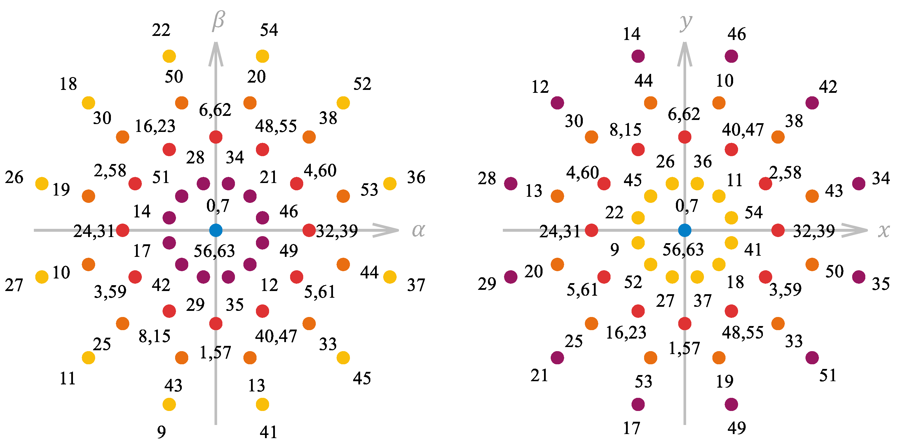
After this change of reference frame, the voltage vectors produced by each switching state can be classified according to its modulus in the main subspace in five groups: large ( v L ), medium-large ( v M L ), small ( v S ), and null ( v 0 ). These voltage vectors are shown in Figure 2, where an annotation marks the number produced by the vector composed of S i j .
To further simplify drive control, it is desirable to decouple flux and torque production through the Park rotation matrix (5) [53]. This transformation projects α β components onto the rotating d q frame, with d current affecting flux production and q current accounting for torque once the d current has been fixed. In order to apply this matrix, it is necessary to estimate the angle of the reference frame with the rotor flux position ( θ r ), obtained through the measured speed and the estimated slip.
[ D ] = cos θ r sin θ r sin θ r cos θ r ,
v d , v q T = [ D ] · v α , v β T .

3. MPC Fundamentals

3.1. Standard MPC

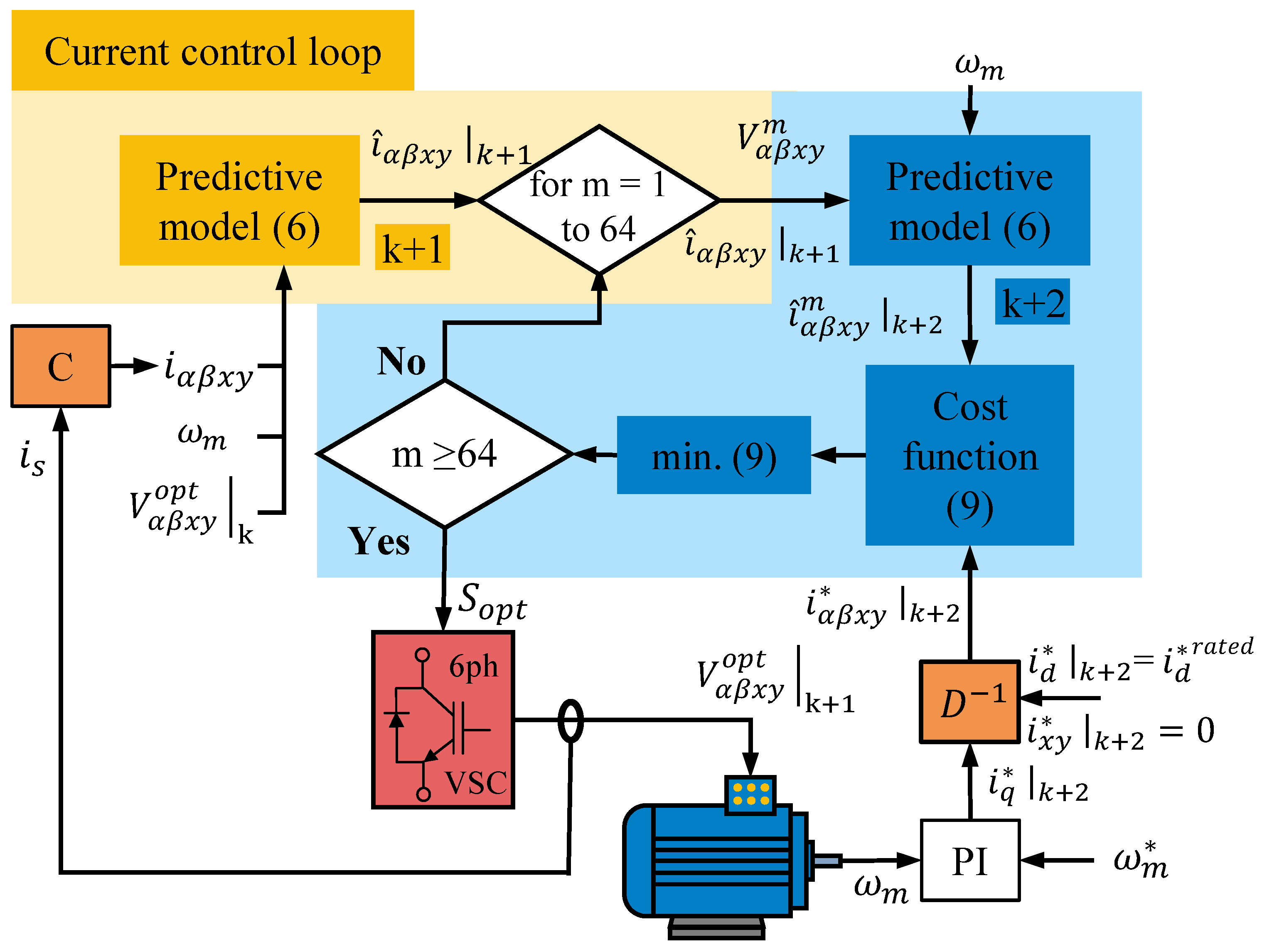
In the case of variable-speed EDs, model predictive control is characterized by two regulation loops, as shown in the diagram of Figure 3. The external control loop focuses on tracking the reference mechanical speed ( ω m ), and it is governed by a proportional-integral (PI) controller that provides the q reference current ( i q ). The remaining reference currents are typically specified as follows: i d adjusted to ensure rated flux while both i x and i y set to zero when harmonic injection is not desired. The internal control loop aims to regulate these currents and is implemented using the following model of the 6ph-IM:
d d t X α β x y = A X α β x y + B U α β x y , U α β x y = v α , v β , v x , v y , v z 1 , v z 2 T , X α β x y = i α , i β , i x , i y , λ α , λ β T ,
A = a 11 a 12 0 0 a 15 a 16 a 21 a 22 0 0 a 25 a 26 0 0 a 33 0 0 0 0 0 0 a 44 0 0 a 51 a 52 0 0 a 55 a 56 a 61 a 62 0 0 a 65 a 66 , B = b 11 0 0 0 0 b 22 0 0 0 0 b 33 0 0 0 0 b 44 b 51 0 0 0 0 b 62 0 0 .
The matrices [ A ] and [ B ] describe the behavior of the drive, and their coefficients are composed of the following expressions based on machine parameters:
a 11 = a 22 = R s L r L s L r L m 2 , a 12 = a 21 = L m 2 ω r L s L r L m 2 , a 15 = a 26 = R s L r L s L r L m 2 , a 16 = a 25 = L m L r ω r L s L r L m 2 , a 33 = a 44 = R s L l s , a 51 = a 62 = R s L m L s L r L m 2 , a 52 = a 61 = L s L m ω r L s L r L m 2 , a 55 = a 66 = R r L s L s L r L m 2 , a 56 = a 65 = L r L s ω r L s L r L m 2 , b 11 = b 22 = L r L s L r L m 2 , b 33 = b 44 = 1 L l s , b 51 = b 62 = L m L s L r L m 2 ;
where R stands for resistance and L for inductance, with the subscripts s and r representing stator and rotor values, respectively. Finally, L m , and L l s represent the mutual and leakage stator inductance, and ω r the electrical speed of the rotor currents.
The presented model is discretized using the Euler method for ease of implementation. The predictive model is first used to estimate the currents at the instant k + 1 (see Figure 3), using the measured currents in the VSD frame of reference ( i α β x y ), ω m and the voltages produced by the switching state deemed as optimal for the present instant, V α β x y o p t | k , which is currently being applied. This intermediate step in the prediction process is termed one-step delay (OSD) compensation, and it is required due to real-time implementation constraints [54]. For the instant k + 2 , every available control action is evaluated using (6), with m ranging from 1 to 64. The resulting predicted currents are then compared with their corresponding reference variables using the following cost function:
J m = e α m + e β m + K x y · e x y m ,
e α m = ( i α | k + 2 ı ^ α m | k + 2 ) 2 , e β m = ( i β | k + 2 ı ^ β m | k + 2 ) 2 , e x y m = ( i x | k + 2 ı ^ x m | k + 2 ) 2 + ( i y | k + 2 ı ^ y m | k + 2 ) 2 ,
where K x y is a weighting factor (WF) that assigns different degrees of importance to each control objective and the superscript “ ^ ” denotes the predicted variables. By minimizing (9), the algorithm finds the optimal switching state ( S o p t ) for the established objectives, and it will be applied in the next sampling period.

3.2. Multivector Schemes

The use of a single switching state per sampling period, specifically at low-to-medium control frequencies, constitutes the primary limitation of conventional FCS-MPC with respect to current quality. The cost function defined in (9) includes, as control objectives, the minimization of current errors in the α β subspace (i.e., active voltage generation in the main plane) and the minimization of x y currents. Unfortunately, as shown in Figure 2, all active switching states in the main subspace are associated with the generation of an active voltage in the secondary plane. Therefore, if only one switching state is applied per sampling period, it is not possible to simultaneously satisfy both control objectives.
To overcome this limitation, multivector MPC emerges as a viable solution to synchronously achieve both regulation objectives [38]. In this approach, several switching states are combined within a single control period to ensure active voltage generation in the main plane while at the same time reducing voltage generation in the secondary plane. Nevertheless, as described in [36], ensuring zero-average voltage is not sufficient to mitigate harmonic injection, because the effect of instantaneous voltage production in the x y plane cannot be neglected. This phenomenon is referred to as average deception in [29].
In this regard, the first set of control actions capable of reducing instantaneous voltage generation in the secondary plane was defined in [36]. This regulation technique combines two adjacent v L vectors in the α β plane, applied in equal proportion within a control period, termed as large virtual voltage vectors (LVVs). The resulting voltage in the secondary plane when these switching states are applied is not zero. However, the instantaneous harmonic injection is minimized, because large voltage vectors in the main plane are mapped onto small voltage vectors in the x y subspace. This approach reduces the total harmonic distortion (THD) of the stator phase currents and, consequently, enhances the overall performance of the ED. Regarding the main plane, the use of LVVs increases the utilization of the available dc link compared to other multivector techniques, such as those presented in [29,38,47,51]. Finally, the use of LVVs as control actions also has a positive impact in terms of switching losses, since only one transition in the VSC legs is required to switch between adjacent large voltage vectors.

4. The Effect of Secondary Current Control on the ED Performance

4.1. Open-Loop Control of the x y Currents

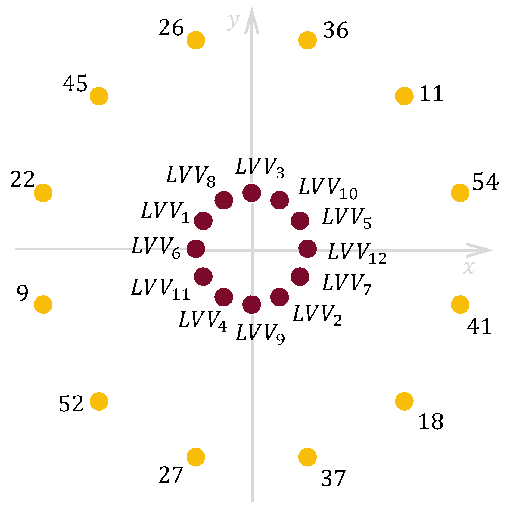
There is an additional advantage of using LVVs as control actions, which is related to the regulation of the x y currents. As shown in Figure 4, the voltage produced by each LVV in the secondary plane has the same amplitude and is relatively low value compared to the voltage produced by each switching state independently. For this reason, the excitation of the x y plane is inherently limited by the control actions themselves, making it possible to carry out the regulation of the secondary components in open-loop mode. Therefore, the equations related to the prediction of x y currents in (6) and the terms included in the cost function (9) can be eliminated, reducing the computational burden and simplifying the regulation technique.
Nevertheless, a critical limitation arises when the control of the secondary components is implemented in open-loop mode. On the one hand, although the LVVs contribute minimally to the secondary plane, this subspace plays a critical role in some multiphase machines, as reduced voltage generation leads to increased current injection [55]. Consequently, the fifth and seventh harmonics, which naturally appear when the x y subspace of the machine under study is excited, are amplified and cannot be reduced when using an open-loop control. On the other hand, there are physical phenomena that can directly affect voltage generation in the secondary plane. For instance, the presence of spatial harmonics in the machine can increase the x y voltages, making the regulation of secondary components necessary to minimize their impact on the electric drive performance. Similarly, significant variation in electrical parameters between phases—either due to winding deterioration or a construction error—promote the appearance of asymmetries in the stator phase currents. These imbalances excite the secondary plane, thereby affecting the overall system response.
In light of these effects, it becomes necessary to reintroduce closed-loop control of the secondary currents to achieve a suitable performance of the multiphase ED under the described conditions.

4.2. Proposed Control Scheme

The proposed control scheme combines the main benefits of using a multivector solution in FCS-MPC, i.e., mitigating residual voltages, reducing the harmonic production in the x y plane, and the benefits of using closed-loop control, i.e., the mitigation of harmful effects as a consequence of dissymmetries, spatial harmonics, or nonlinearities of the VSC. By combining these two approaches, the designed CLVV-MPC provides enhanced current quality and improved mitigation of asymmetries compared with the standard LVV-MPC proposed in [36].
The CLVV-MPC employs, as active control actions, twelve tuples of adjacent v L in the main plane. The resulting voltage ( V α β x y L V V m ) of these tuples can be obtained according to (11):
V α β x y L V V m = T m 2 · V α β x y i + T m 2 · V α β x y j ,
where Tm is the sampling period employed by the regulation technique and the superscripts i and j denote adjacent v L . The set of available control actions is completed including a null voltage vector.
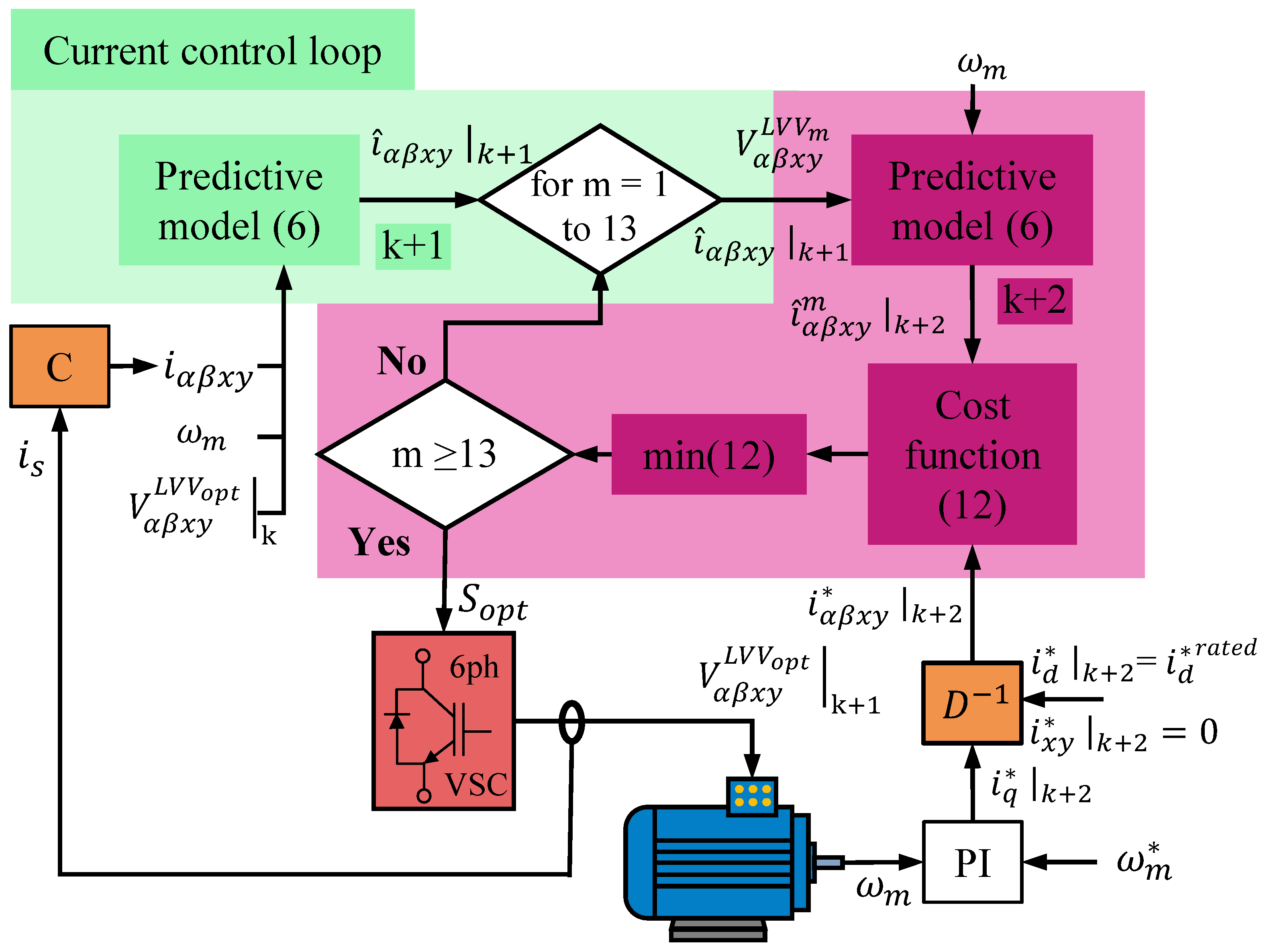
A diagram of the proposed control scheme is shown in Figure 5. As illustrated in Figure 5, CLVV-MPC employs the predictive model defined in (6), which in this case considers the voltage provided by each LVV as defined in (11). As in the case of the FCS-MPC, the OSD is maintained to ensure proper behavior of the regulation technique when it is implemented in real-time systems. The cost function can be defined as in (12):
J L V V m = e α L V V m + e β L V V m + K x y · e x y L V V m ,
where:
e α L V V m = ( i α * | k + 2 ı ^ α L V V m | k + 2 ) 2 , e β L V V m = ( i β | k + 2 ı ^ β L V V m | k + 2 ) 2 , e x y L V V m = ( i x | k + 2 ı ^ x L V V m | k + 2 ) 2 + ( i y | k + 2 ı ^ y L V V m | k + 2 ) 2 ,
where m ranges from 1 to 13 to evaluate the control error of all the available LVVs.
In this way, by incorporating closed-loop control of the secondary components, the CLVV-MPC retains the advantages outlined in Section 3.2, while also gaining the capability to suppress x y voltage generation under different operating scenarios. These conditions may result either from the applied control actions or from asymmetries, nonlinearities, and spatial harmonics in the electrical machine. This combination ensures a significant improvement of the current quality in the multiphase ED.

5. Experimental Results

5.1. Test Bench

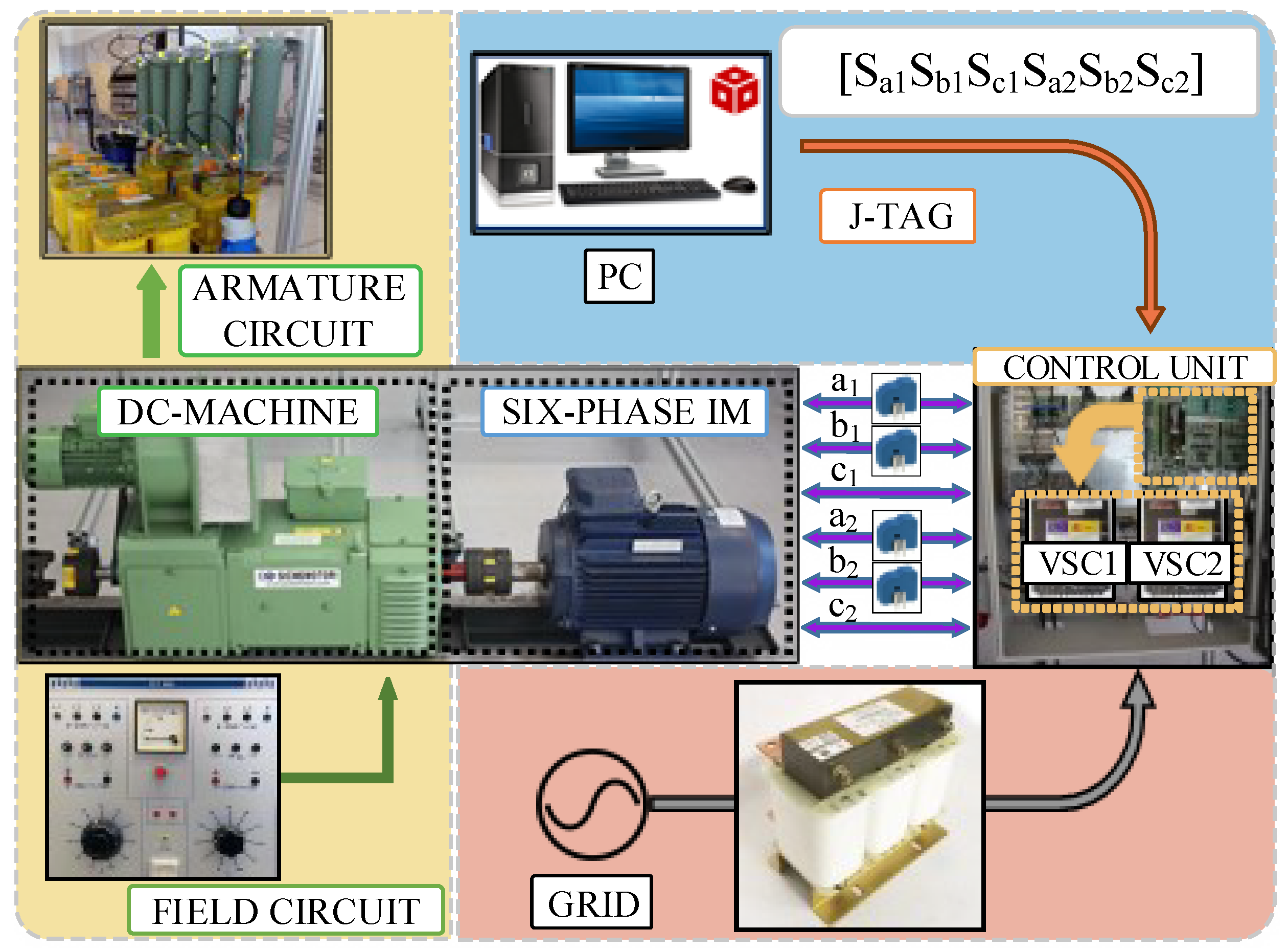
The experimental rig employed in the presented work is depicted in Figure 6. The 6ph-IM described in Section 2 is fed by two VSCs (Semikron SKS22F, Nuremberg, Germany) connected to the grid via one transformer. Its rectification stages provide two dc links of the same voltage. As for the machine itself, its parameters have been determined using the ac time-domain and stand-still tests when the motor was fed by an inverter [56,57]. Their values, alongside the parameters which define the performed tests in terms of control, are shown in Table 1. The 6ph-IM is coupled to a dc machine serving as a generator, with an armature circuit presenting variable resistances to dissipate energy. Due to the described configuration, the load of the 6ph-IM is speed-dependent. Focusing on the control algorithms employed in this work, they have been developed on Texas Instrument’s proprietary software (Code Composer Studio 5.3.0, Texas Instrument, Dallas, TX, USA), and later implemented in the digital signal processor of the same company (TMS320F28335, Texas Instrument, Dallas, TX, USA) through a JTAG interface. The information required to close the control loops is provided by two types of sensors: an optical encoder to obtain mechanical speed (GHN510296R, Hohner Automation, Frankfurt, Germany) and four Hall-effect sensors (LEM LAH 25-NP, Meyrin, Switzerland) to measure stator currents. With the objective of obtaining a more complete depiction of the current harmonic spectrum, the phase currents depicted in this section have been measured with a different setup. Four Hall-effect sensors, model BK PRECISION CP62 (BK PRECISION, Yorba Linda, CA, USA), feed the acquired information to an oscilloscope (Yokogawa DL850 ScopeCorder, Tokyo, Japan), recording at a rate of 200,000 samples per second, a sampling time of 5 μ s. This information is transferred offline to a PC through a USB drive and processed through the software MATLAB 2023a.

5.2. Comparative Evaluation

With the objective of comparing the performance of the proposed method against the selected benchmark, LVV-MPC, four sets of tests have been designed. Test 1 shows the performance of both control schemes at two operating points, focusing on quality indices such as a harmonic distortion index (HDI) [58], THD based on IEEE Std 519-2022 [59], and switching frequency ( f s w ) to provide some notions of the improvement in copper and switching losses, respectively. Test 2 is designed to showcase the differences in system response to phase dissymmetry depending on the method used. Test 3 illustrates the dynamic behavior of the drive under both control schemes in response to changes in the reference speed. Test 4 examines the transient response following variations in the load torque. Finally, the computational burden of the considered schemes is presented.
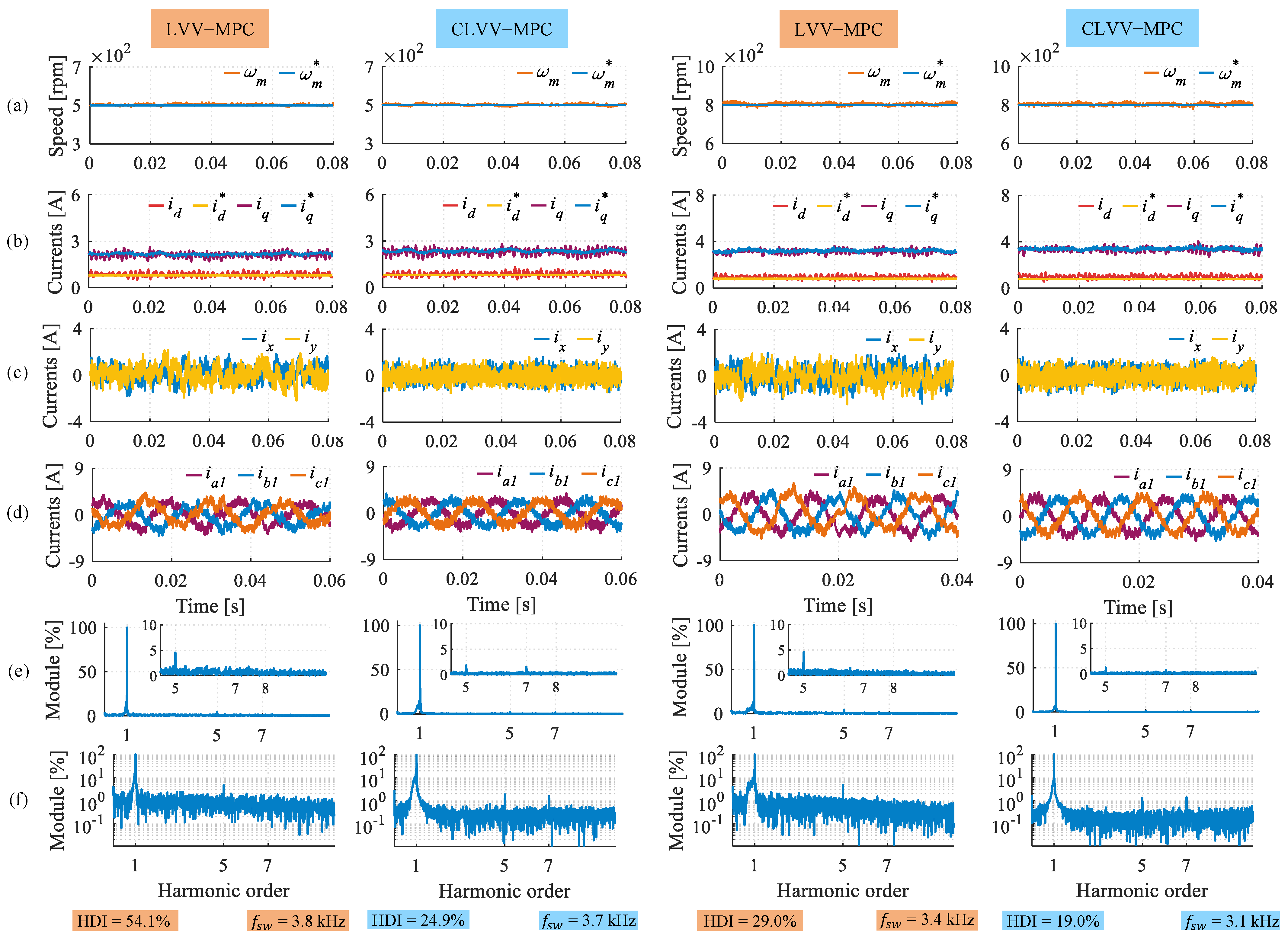
The results of the first set of tests are displayed in Figure 7, with the two left columns depicting the machine performance at 500 rpm and the two right columns at 800 rpm. By observing Figure 7a,b, the correct tracking of reference speed and currents in the d q plane can be confirmed for both schemes and operating points. However, stark differences appear when comparing x y currents (Figure 7c) and phase currents (Figure 7d). CLVV-MPC achieves lower harmonic injection at low and high speed, leading thus to lower HDI values. At 500 rpm, this metric registers a relative reduction of 54%, while f s w is maintained. At 800 rpm, HDI is reduced by 35% while f s w drops lightly by 9%. This improvement can also be observed by employing the fast Fourier transform (FFT) on the phase currents (Figure 7e,f). While the harmonic content is reduced in a general manner, the greatest improvement comes in the reduction of the fifth harmonic, which is reduced from 4.56% to 1.88% at 500 rpm and from 4.57% to 1.25% at 800 rpm. The discussed quality metrics are collected in Table 2, alongside the THD values of phase currents. In summary, closing the regulation loop of the secondary currents is key to ensuring phase current quality in the whole operating range and, if correctly tuned, it does not imply notable worsening of primary-currents tracking.
Regarding Test 2, a resistor of 2.5 Ω has been connected in series with the phase a 1 of the 6ph-IM, creating a resistance asymmetry situation [60,61]. The effects on the drive performance can be observed in Figure 8 for both studied control schemes. Although speed and current tracking are similarly satisfied (Figure 8a,b), the unbalance in secondary and phase currents (Figure 8c,d) presents stark improvement once CLVV-MPC is implemented. In order to quantify this effect, the difference between the root mean squared error of phase a 1 and b 1 ( δ p h r m s ) has been measured. Although the proposed method does not completely eliminate the dissymmetry, δ p h r m s is improved by 64%, clearly showcasing this advantage over schemes with open-loop secondary currents. This is, again, reflected in the FFT decomposition of phase currents (Figure 8e and Figure 7f). More concretely, the fifth harmonic is reduced from 7.38% to 0.74% when comparing LVV-MPC and the proposed method.
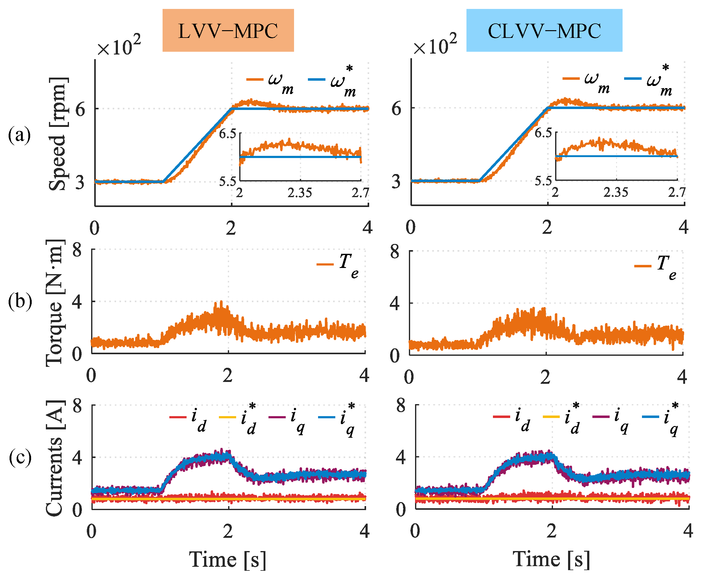
Completing the analysis, Test 3 displays the dynamic behavior of the benchmark and proposed methods in a symmetrical scenario, with Figure 9a showcasing speed response, Figure 9b displaying electromagnetic torque estimated through measured currents [8], and Figure 9c showing d q current tracking. Both controllers have received a reference-speed ramp, going from 300 to 600 rpm in one second. By observing the presented plots, it can be stated that the modifications implemented in CLVV-MPC do not compromise dynamic response when compared to LVV-MPC.
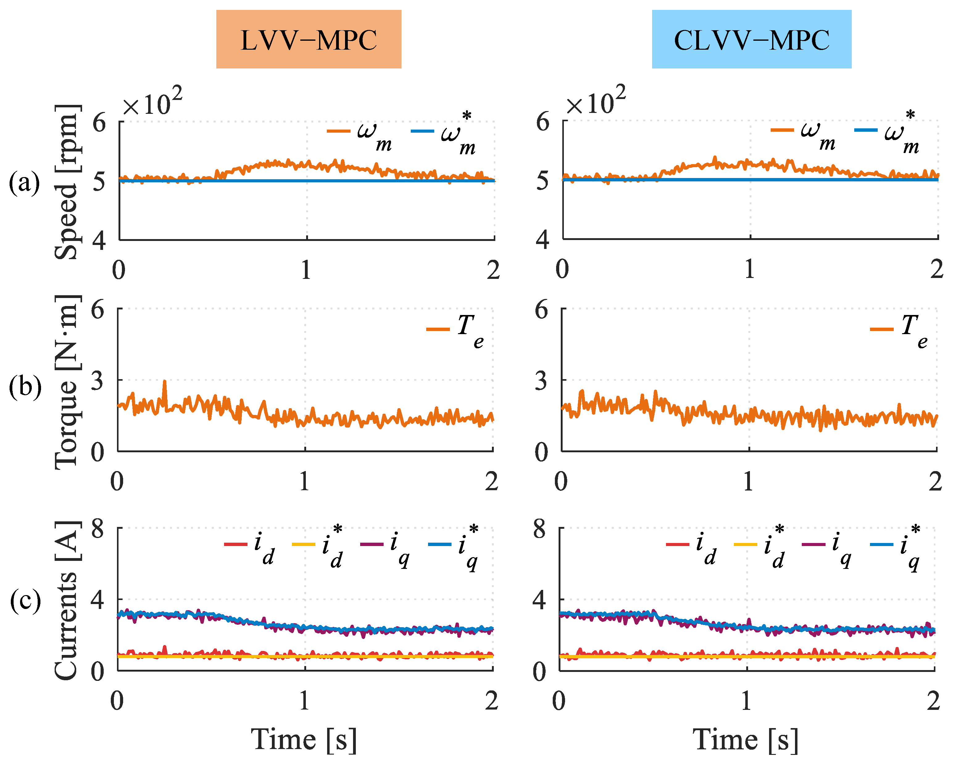
The dynamic response of the proposed CLVV-MPC is evaluated under a load torque variation in Test 4 (see Figure 10). This transient condition is emulated by modifying the resistance coupled to the dc-machine armature at t = 0.5 s. Regardless of the control scheme, both approaches achieve suitable tracking of the main currents (Figure 10b). Consequently, the load torque variation only results in a slight increase in the mechanical speed, as illustrated in Figure 10a.
Finally, the computational times of the considered control schemes are presented in Table 3. To provide a comprehensive overview of the proposed scheme from this perspective, the computational burden of conventional FCS-MPC has also been included. Due to the need to estimate secondary currents, CLVV-MPC exhibits a higher computational cost than the standard LVV-MPC. Nevertheless, since a reduced number of switching states are evaluated per control step, the designed control solution requires less computational time than conventional MPC. Regarding real-world applications, this computational cost can be considered acceptable for typical control frequencies. These results confirm again that the reduction in harmonic distortion does not compromise the dynamic response.
In summary, implementing a closed-loop regulation approach to the secondary currents in FCS-MPC without null-average x y voltage vectors improves the drives performance in two significant ways: (i) Undesirable harmonic injection is reduced in the whole operating range; and (ii) the regulation algorithm is now able to remarkably reduce possible dissymmetries between phases. Furthermore, these improvements are achieved without compromising d q -current tracking or the dynamic response of the system.

6. Conclusions

The multivector approaches applied to direct control schemes have demonstrated significant benefits, notably improving current quality and enhanced fault tolerance. In particular, FCS-MPC schemes offer high flexibility incorporating multiple control objectives. This feature enables the evaluation and application of control actions to properly adapt to the required voltage conditions and switching frequency across different operating points. However, VVV-based predictive schemes that apply control actions including active non- v L are subject to the average deception phenomenon, which leads to a degradation in phase current quality and overall ED performance. In contrast, v L -based multivector approaches avoid this phenomenon and enable effective open-loop predictive control performance. Unfortunately, the implementation of this open-loop control overlooks the compensation of the low-order x y current harmonics resulting from residual voltages in the secondary subspace, nonlinearities, or asymmetries inherent to the ED or arising during its operation. Therefore, the proposed CLVV-MPC approach effectively integrates the advantages of multivector control with the additional capabilities gained by implementing closed-loop regulation in the x y subspace. The implementation of this closed loop for regulating the secondary currents is straightforward and relies on the cost function already embedded in the control scheme, which evaluates the control actions to be applied by the VSC.
As demonstrated, the secondary current closed-loop integrated into CLVV-MPC ensures consistent performance within the same operating range as that of the selected benchmark. This is achieved with a significant improvement in current quality: 54% at 500 rpm while maintaining the same switching frequency, or 35% at 800 rpm with a 9% reduction in switching frequency. The experimental tests show that the regulation loop effectively mitigates both the residual harmonic currents introduced by the control action and those caused by nonlinearities and back-EMF, which are typically observed in open-loop multivector operation. Furthermore, CLVV-MPC effectively reduces disturbances caused by occasional resistance asymmetries in the multiphase ED. As a result, CLVV-MPC maintains proper ED performance and improved current quality under a significant variation in stator resistance. This is evidenced by a 64% reduction in the impact on the ED phase currents in the event of a sudden dissymmetry caused by a 60% increase in R s . In contrast, under the same conditions, LVV-MPC experiences a noticeable degradation in the phase current signal. Taken together with a comparable dynamic response, these results experimentally confirm that CLVV-MPC enhances the performance achieved by the multivector approach LVV-MPC under open-loop harmonic current control.

Author Contributions

Conceptualization, J.C.-R., A.G.-P., and J.J.A.; methodology, J.C.-R., A.G.-P., and J.J.A.; software, J.C.-R., J.J.A., and A.G.-P.; validation, J.C.-R., J.J.A., and A.G.-P.; formal analysis, J.C.-R. and I.G.-P.; investigation, J.J.A., A.G.-P., and J.C.-R.; resources, I.G.-P. and M.J.D.; data curation, J.C.-R., I.G.-P., A.G.-P., J.J.A., and R.L.-L.; writing—original draft preparation, J.C.-R., A.G.-P., and J.J.A.; writing—review and editing, R.L.-L., M.J.D., and I.G.-P.; visualization, R.L.-L., A.G.-P., and J.J.A.; supervision, M.J.D., I.G.-P., and J.C.-R.; project administration, I.G.-P. and M.J.D.; funding acquisition, I.G.-P. and M.J.D. All authors have read and agreed to the published version of the manuscript.

Funding

This research was funded in part by the Spanish Government under the Plan Estatal with the references PID2021-127131OB-I00 and PID2024-158852OB-I00, in part by Proyectos Estratégicos Orientados a la Transición Ecológica y a la Transición Digital under the reference TED2021-129558B-C21.

Institutional Review Board Statement

Not applicable.

Informed Consent Statement

Not applicable.

Data Availability Statement

Data is contained within the article.

Conflicts of Interest

The authors declare no conflicts of interest.

Abbreviations

The following abbreviations are used in this manuscript:
6ph-IMSix-phase induction machine.
CLVV-MPCClosed-loop large virtual vector model predictive control.
CMVCommon-mode voltage vector.
EDElectric drive.
FCS-MPCFinite-control set model predictive control.
FFTFast Fourier transform.
FOCField-oriented control.
HDIHarmonic distortion index.
THDTotal harmonic Distortion.
VSCVoltage source converter.
VSDVector space decomposition.
VVVVirtual voltage vector.

References

  1. Frikha, M.A.; Croonen, J.; Deepak, K.; Benômar, Y.; El Baghdadi, M.; Hegazy, O. Multiphase Motors and Drive Systems for Electric Vehicle Powertrains: State of the Art Analysis and Future Trends. Energies 2023, 16, 768. [Google Scholar] [CrossRef]
  2. Mercedes AMG EQS 53. Available online: https://mercedes-benz-media.co.uk/releases/1618 (accessed on 16 September 2025).
  3. BMW iX M60. Available online: https://www.motortrend.com/news/2023-bmw-ix-m60-xdrive50-edrive-electric-motors-explained (accessed on 16 September 2025).
  4. Xue, Z.; Niu, S.; Chau, A.M.H.; Luo, Y.; Lin, H.; Li, X. Recent Advances in Multi-Phase Electric Drives Model Predictive Control in Renewable Energy Application: A State-of-the-Art Review. World Electr. Veh. J. 2023, 14, 44. [Google Scholar] [CrossRef]
  5. Andresen, B.; Birk, J. A high power density converter system for the Gamesa G10x 4,5 MW wind turbine. In Proceedings of the 2007 European Conference on Power Electronics and Applications, Aalborg, Denmark, 2–5 September 2007; pp. 1–8. [Google Scholar] [CrossRef]
  6. Alvarez, P.; Satrústegui, M.; Elósegui, I.; Martinez-Iturralde, M. Review of High Power and High Voltage Electric Motors for Single-Aisle Regional Aircraft. IEEE Access 2022, 10, 112989–113004. [Google Scholar] [CrossRef]
  7. Zeroavia EPS. Available online: https://zeroavia.com/electric-propulsion/ (accessed on 16 September 2025).
  8. Levi, E.; Bojoi, R.; Profumo, F.; Toliyat, H.; Williamson, S. Multiphase induction motor drives—A technology status review. IET Electr. Power Appl. 2007, 1, 489–516. [Google Scholar] [CrossRef]
  9. Levi, E. Advances in Converter Control and Innovative Exploitation of Additional Degrees of Freedom for Multiphase Machines. IEEE Trans. Ind. Electron. 2016, 63, 433–448. [Google Scholar] [CrossRef]
  10. Yang, G.; Hussain, H.; Li, S.; Zhang, X.; Yang, J.; Lee, C.H.T. Design and Analysis of Universal Natural Fault-Tolerant SVPWM Strategy with Simplified Fault Diagnosis for Multiphase Motor Drives. IEEE J. Emerg. Sel. Top. Power Electron. 2023, 11, 4340–4354. [Google Scholar] [CrossRef]
  11. Jung, E.; Yoo, H.; Sul, S.K.; Choi, H.S.; Choi, Y.Y. A Nine-Phase Permanent-Magnet Motor Drive System for an Ultrahigh-Speed Elevator. IEEE Trans. Ind. Appl. 2012, 48, 987–995. [Google Scholar] [CrossRef]
  12. Zhang, M.; Yuan, M.; Jiang, J. A Comprehensive Review of the Multiphase Motor Drive Topologies for High-Power Electric Vehicle: Current Status, Research Challenges, and Future Trends. IEEE Trans. Transp. Electrif. 2025, 11, 3631–3654. [Google Scholar] [CrossRef]
  13. Levi, E. Multiphase Electric Machines for Variable-Speed Applications. IEEE Trans. Ind. Electron. 2008, 55, 1893–1909. [Google Scholar] [CrossRef]
  14. Furmanik, M.; Gorel, L.; Konvičný, D.; Rafajdus, P. Comparative Study and Overview of Field-Oriented Control Techniques for Six-Phase PMSMs. Appl. Sci. 2021, 11, 7841. [Google Scholar] [CrossRef]
  15. Liu, Z.; Li, Y.; Zheng, Z. A review of drive techniques for multiphase machines. CES Trans. Electr. Mach. Syst. 2018, 2, 243–251. [Google Scholar] [CrossRef]
  16. Bermúdez, M.; Barrero, F.; Martín, C.; Perales, M. Performance Analysis of Direct Torque Controllers in Five-Phase Electrical Drives. Appl. Sci. 2021, 11, 11964. [Google Scholar] [CrossRef]
  17. Rodriguez, J.; Garcia, C.; Mora, A.; Flores-Bahamonde, F.; Acuna, P.; Novak, M.; Zhang, Y.; Tarisciotti, L.; Davari, S.A.; Zhang, Z.; et al. Latest Advances of Model Predictive Control in Electrical Drives—Part I: Basic Concepts and Advanced Strategies. IEEE Trans. Power Electron. 2022, 37, 3927–3942. [Google Scholar] [CrossRef]
  18. Rodriguez, J.; Garcia, C.; Mora, A.; Davari, S.A.; Rodas, J.; Valencia, D.F.; Elmorshedy, M.; Wang, F.; Zuo, K.; Tarisciotti, L.; et al. Latest Advances of Model Predictive Control in Electrical Drives—Part II: Applications and Benchmarking with Classical Control Methods. IEEE Trans. Power Electron. 2022, 37, 5047–5061. [Google Scholar] [CrossRef]
  19. Singh, G.K.; Nam, K.; Lim, S.K. A simple indirect field-oriented control scheme for multiphase induction machine. IEEE Trans. Ind. Electron. 2005, 52, 1177–1184. [Google Scholar] [CrossRef]
  20. Che, H.S.; Levi, E.; Jones, M.; Hew, W.P.; Rahim, N.A. Current Control Methods for an Asymmetrical Six-Phase Induction Motor Drive. IEEE Trans. Power Electron. 2014, 29, 407–417. [Google Scholar] [CrossRef]
  21. Lopez, O.; Álvarez, J.; Malvar, J.; Yepes, A.G.; Vidal, A.; Baneira, F.; Pérez-Estévez, D.; Freijedo, F.D.; Doval-Gandoy, J. Space-Vector PWM with Common-Mode Voltage Elimination for Multiphase Drives. IEEE Trans. Power Electron. 2016, 31, 8151–8161. [Google Scholar] [CrossRef]
  22. Ayala, M.; Doval-Gandoy, J.; Rodas, J.; Gonzalez, O.; Gregor, R.; Rivera, M. A Novel Modulated Model Predictive Control Applied to Six-Phase Induction Motor Drives. IEEE Trans. Ind. Electron. 2021, 68, 3672–3682. [Google Scholar] [CrossRef]
  23. Aciego, J.J.; Gonzalez-Prieto, I.; Duran, M.J.; Gonzalez-Prieto, A.; Carrillo-Rios, J. Guiding the Selection of Multi-Vector Model Predictive Control Techniques for Multiphase Drives. Machines 2024, 12, 115. [Google Scholar] [CrossRef]
  24. Wang, W.; Fan, Y.; Chen, S.; Zhang, Q. Finite control set model predictive current control of a five-phase PMSM with virtual voltage vectors and adaptive control set. CES Trans. Electr. Mach. Syst. 2018, 2, 136–141. [Google Scholar] [CrossRef]
  25. da Paz, G.F.; Melo, V.F.M.B.; de Freitas, I.S.; de Sousa, R.P.R.; Salvadori, F. Virtual Vector Direct Torque Control for a Nine-Phase Induction Machine Drive System with Eight Active Voltage Vectors Emulating Virtual Voltage Vectors. IEEE Trans. Power Electron. 2024, 39, 9457–9469. [Google Scholar] [CrossRef]
  26. Rodas, J.; Gonzalez, O.; Maidana, P.; Medina, C.; Doval-Gandoy, J.; Norambuena, M.; Ayala, M.; Rodriguez, J. Sequential Model Predictive Torque Control for Six-Phase Machines Without Weighting Factors. IEEE Open J. Power Electron. 2025, 6, 802–810. [Google Scholar] [CrossRef]
  27. Huang, L.; Ji, J.; Zhao, W.; Tao, T.; Cui, J. Duty-Ratio-Based Direct Torque Control with Enhanced Harmonic Current Suppression for Dual-Three-Phase Permanent Magnet Motor. IEEE Trans. Power Electron. 2022, 37, 11098–11108. [Google Scholar] [CrossRef]
  28. Gonçalves, P.; Cruz, S.; Mendes, A. Finite Control Set Model Predictive Control of Six-Phase Asymmetrical Machines—An Overview. Energies 2019, 12, 4693. [Google Scholar] [CrossRef]
  29. Duran, M.J.; Gonzalez-Prieto, I.; Gonzalez-Prieto, A.; Aciego, J.J. The Evolution of Model Predictive Control in Multiphase Electric Drives: A Growing Field of Research. IEEE Ind. Electron. Mag. 2022, 16, 29–39. [Google Scholar] [CrossRef]
  30. Kouro, S.; Perez, M.A.; Rodriguez, J.; Llor, A.M.; Young, H.A. Model Predictive Control: MPC’s Role in the Evolution of Power Electron. IEEE Ind. Electron. Mag. 2015, 9, 8–21. [Google Scholar] [CrossRef]
  31. Arahal, M.; Satué, M.; Barrero, F. Multi-phase weighted stator current tracking using a hyper-plane partition of the control set. Control Eng. Pract. 2024, 153, 106114. [Google Scholar] [CrossRef]
  32. Ayala, M.; Doval-Gandoy, J.; Rodas, J.; Gonzalez, O.; Gregor, R. Current control designed with model based predictive control for six-phase motor drives. ISA Trans. 2020, 98, 496–504. [Google Scholar] [CrossRef] [PubMed]
  33. Arahal, M.R.; Satué, M.G.; Barrero, F.; Ortega, M.G. Adaptive Cost Function FCSMPC for 6-Phase IMs. Energies 2021, 14, 5222. [Google Scholar] [CrossRef]
  34. Abbaszadeh, A.; Khaburi, D.A.; Mahmoudi, H.; Rodríguez, J. Simplified model predictive control with variable weighting factor for current ripple reduction. IET Power Electron. 2017, 10, 1165–1174. [Google Scholar] [CrossRef]
  35. Bhowate, A.; Aware, M.; Sharma, S.; Tatte, Y. Predictive Torque Control for Five Phase Induction Motor Drive with Common Mode Voltage Reduction. In Proceedings of the 2018 International Power Electronics Conference (IPEC-Niigata 2018-ECCE Asia), Niigata, Japan, 20–24 May 2018; pp. 1730–1735. [Google Scholar] [CrossRef]
  36. Durán, M.J.; Gonzalez-Prieto, I.; Gonzalez-Prieto, A. Large virtual voltage vectors for direct controllers in six-phase electric drives. Int. J. Electr. Power Energy Syst. 2021, 125, 106425. [Google Scholar] [CrossRef]
  37. Garcia-Entrambasaguas, P.; Zoric, I.; González-Prieto, I.; Duran, M.J.; Levi, E. Direct Torque and Predictive Control Strategies in Nine-Phase Electric Drives Using Virtual Voltage Vectors. IEEE Trans. Power Electron. 2019, 34, 12106–12119. [Google Scholar] [CrossRef]
  38. Gonzalez-Prieto, I.; Duran, M.J.; Aciego, J.J.; Martin, C.; Barrero, F. Model Predictive Control of Six-Phase Induction Motor Drives Using Virtual Voltage Vectors. IEEE Trans. Ind. Electron. 2018, 65, 27–37. [Google Scholar]
  39. González-Prieto, A.; González-Prieto, I.; Duran, M.J.; Aciego, J.J.; Salas-Biedma, P. Current Harmonic Mitigation Using a Multi-Vector Solution for MPC in Six-Phase Electric Drives. IEEE Access 2021, 9, 117761–117771. [Google Scholar] [CrossRef]
  40. Serra, J.; Bento, F.; Ma, A.J.M. Zero-Sequence Current Mitigation Using a Virtual Voltage Vector Solution for MPC in Symmetrical Six-Phase Electric Drives with Single-Star and Hexagon Winding Configurations. IEEE J. Emerg. Sel. Top. Power Electron. 2025, 13, 1601–1614. [Google Scholar] [CrossRef]
  41. Zhang, T.; Zhang, Y.; Ran, Y.; Wei, H.; Cui, J. Dual Three-Phase Permanent Magnet Multi-Plane Harmonic Closed-Loop Control. In Proceedings of the 2024 5th International Conference on Clean Energy and Electric Power Engineering (ICCEPE), Yangzhou, China, 9–11 August 2024; pp. 1068–1072. [Google Scholar] [CrossRef]
  42. Yan, L.; Zhang, X.; Yang, J.; Yang, G.; Deng, R. Synthetic Vectors-Based Predictive Control of Dual Three-Phase PMSMs for Current Harmonics Mitigation Considering Average Deception Effect. IEEE J. Emerg. Sel. Top. Power Electron. 2024, 12, 3103–3114. [Google Scholar] [CrossRef]
  43. Gonçalves, P.F.; Cruz, S.M.; Mendes, A.M. Bi-subspace predictive current control of six-phase PMSM drives based on virtual vectors with optimal amplitude. IET Electr. Power App. 2019, 13, 1672–1683. [Google Scholar] [CrossRef]
  44. Zhang, Q.; Zhao, J.; Yan, S.; Xiong, Y.; Ma, Y.; Chen, H. Virtual Voltage Vector-Based Model Predictive Current Control for Five-Phase Induction Motor. Processes 2022, 10, 1925. [Google Scholar] [CrossRef]
  45. Yin, R.; Yang, J. Predictive current control for seven-phase induction motor based on the optimal operating time of four-dimensional vector. IET Electr. Power Appl. 2019, 13, 1684–1695. [Google Scholar] [CrossRef]
  46. Cui, J.; Kang, M.; Tao, T.; Zhao, W. Harmonics Suppression for Dual Three-Phase Permanent Magnet motor with Multi-Subspace Model Predictive Control. In Proceedings of the 2023 IEEE 6th International Electrical and Energy Conference (CIEEC), Hefei, China, 12–14 May 2023; pp. 4364–4369. [Google Scholar]
  47. Aciego, J.J.; González Prieto, I.; Duran, M.J. Model Predictive Control of Six-Phase Induction Motor Drives Using Two Virtual Voltage Vectors. IEEE J. Emerg. Sel. Top. Power Electron. 2019, 7, 321–330. [Google Scholar] [CrossRef]
  48. Gonzalez, O.; Ayala, M.; Romero, C.; Delorme, L.; Rodas, J.; Gregor, R.; Gonzalez-Prieto, I.; Duran, M.J. Model Predictive Current Control of Six-Phase Induction Motor Drives Using Virtual Vectors and Space Vector Modulation. IEEE Trans. Power Electron. 2022, 37, 7617–7628. [Google Scholar] [CrossRef]
  49. Luo, Y.; Liu, C. Elimination of Harmonic Currents Using a Reference Voltage Vector Based-Model Predictive Control for a Six-Phase PMSM Motor. IEEE Trans. Power Electron. 2019, 34, 6960–6972. [Google Scholar] [CrossRef]
  50. Pandit, J.K.; Aware, M.V.; Nemade, R.; Tatte, Y. Simplified Implementation of Synthetic Vectors for DTC of Asymmetric Six-Phase Induction Motor Drives. IEEE Trans. Ind. Appl. 2018, 54, 2306–2318. [Google Scholar] [CrossRef]
  51. Aciego, J.J.; González Prieto, I.; Duran, M.J.; Bermudez, M.; Salas-Biedma, P. Model Predictive Control Based on Dynamic Voltage Vectors for Six-Phase Induction Machines. IEEE J. Emerg. Sel. Top. Power Electron. 2021, 9, 2710–2722. [Google Scholar] [CrossRef]
  52. Zhao, Y.; Lipo, T. Space vector PWM control of dual three phase induction machine using vector space decomposition. In Proceedings of the 1994 IEEE Industry Applications Society Annual Meeting, Denver, CO, USA, 2–6 October 1994; Volume 1, pp. 742–749. [Google Scholar]
  53. Park, R.H. Two-reaction theory of synchronous machines generalized method of analysis—Part I. Trans. Am. Inst. Electr. Eng. 1929, 48, 716–727. [Google Scholar] [CrossRef]
  54. Karamanakos, P.; Liegmann, E.; Geyer, T.; Kennel, R. Model Predictive Control of Power Electronic Systems: Methods, Results, and Challenges. IEEE Open J. Ind. App. 2020, 1, 95–114. [Google Scholar] [CrossRef]
  55. Hadiouche, D.; Baghli, L.; Rezzoug, A. Space-vector PWM techniques for dual three-phase AC machine: Analysis, performance evaluation, and DSP implementation. IEEE Trans. Ind. Appl. 2006, 42, 1112–1122. [Google Scholar] [CrossRef]
  56. Yepes, A.G.; Riveros, J.A.; Doval-Gandoy, J.; Barrero, F.; Lopez, O.; Bogado, B.; Jones, M.; Levi, E. Parameter Identification of Multiphase Induction Machines with Distributed Windings—Part 1: Sinusoidal Excitation Methods. IEEE Trans. Energy Convers. 2012, 27, 1056–1066. [Google Scholar] [CrossRef]
  57. Riveros, J.A.; Yepes, A.G.; Barrero, F.; Doval-Gandoy, J.; Bogado, B.; Lopez, O.; Jones, M.; Levi, E. Parameter Identification of Multiphase Induction Machines with Distributed Windings—Part 2: Time-Domain Techniques. IEEE Trans. Energy Convers. 2012, 27, 1067–1077. [Google Scholar] [CrossRef]
  58. Yepes, A.G.; Doval-Gandoy, J.; Toliyat, H. Multifrequency Current Control for Multiphase Machines with Antiwindup, Distortion-Free Saturation and Full DC-Link Utilization. In Proceedings of the 2018 IEEE Energy Conversion Congress and Exposition (ECCE), Portland, OR, USA, 23–27 September 2018; pp. 776–783. [Google Scholar]
  59. IEEE Std 519-2022 (Revision of IEEE Std 519-2014); IEEE Standard for Harmonic Control in Electric Power Systems. IEEE: Piscataway, NJ, USA, 2022; pp. 1–31. [CrossRef]
  60. Yepes, A.G.; Abdel-Azim, W.E.; Shawier, A.; Abdel-Majeed, M.S.; Che, H.S.; Abdel-Khalik, A.S.; Ahmed, S.; Doval-Gandoy, J. Online Control Strategy for Tolerating Resistance Asymmetry with Minimum Copper Loss in the Full Torque Range for Symmetrical Six-Phase AC Drives. IEEE Trans. Power Electron. 2023, 38, 151–164. [Google Scholar] [CrossRef]
  61. Hu, R.; Wang, J.; Mills, A.R.; Chong, E.; Sun, Z. Detection and Classification of Turn Fault and High Resistance Connection Fault in Permanent Magnet Machines Based on Zero Sequence Voltage. IEEE Trans. Power Electron. 2020, 35, 1922–1933. [Google Scholar] [CrossRef]
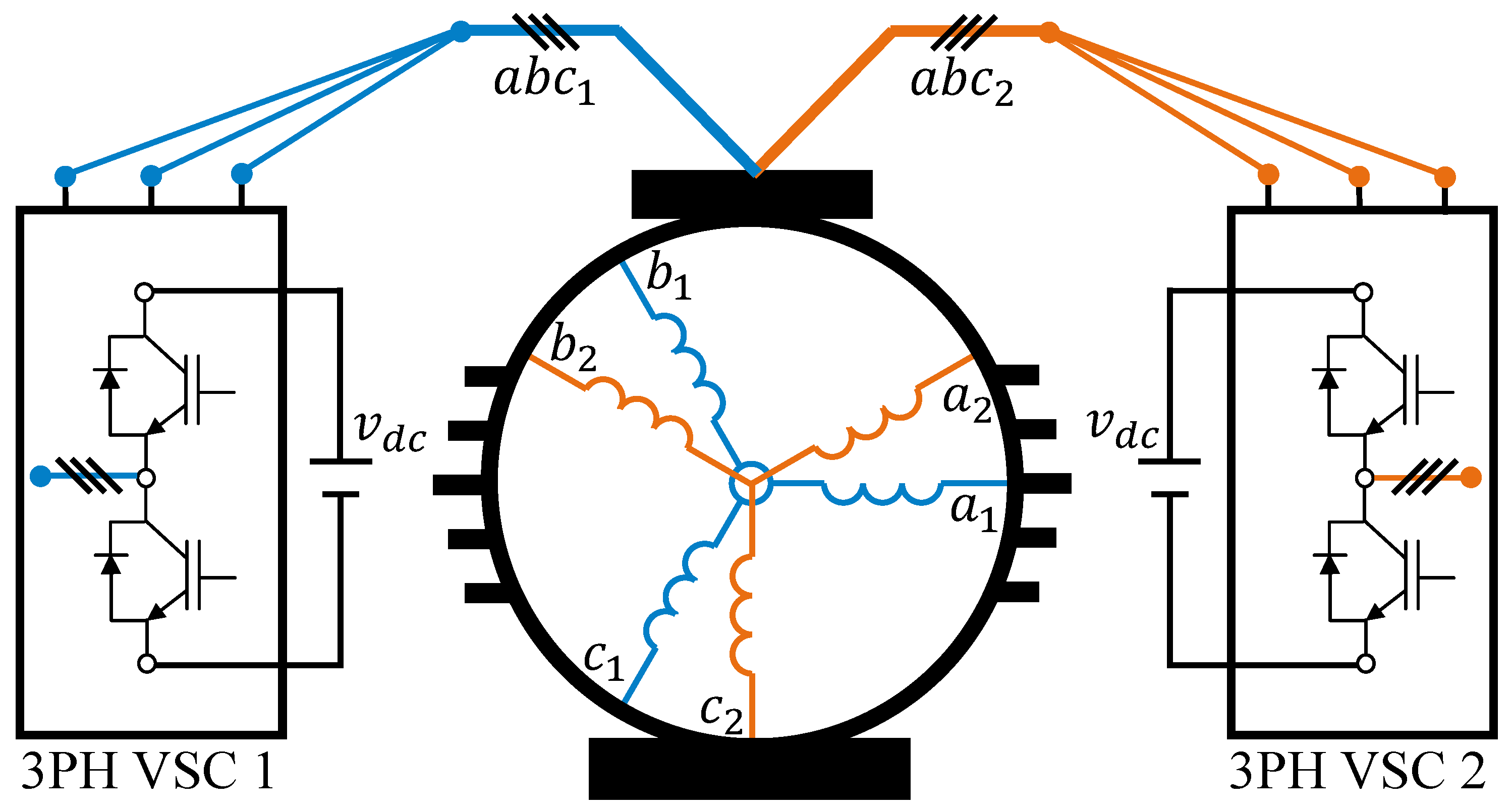
Figure 1. 6ph-IM topology.
Machines 13 00862 g001
Figure 2. Voltage vectors produced by the available switching states in a double three-phase two-level VSC after VSD feeding an asymmetrical 6ph-IM.
Machines 13 00862 g002
Figure 3. Diagram of MPC working process.
Machines 13 00862 g003
Figure 4. Generated voltage in the secondary plane by v L (yellow) and LVVs (burgundy).
Machines 13 00862 g004
Figure 5. Diagram of CLVV-MPC working process.
Machines 13 00862 g005
Figure 6. Diagram of the test rig employed to evaluate the control schemes.
Machines 13 00862 g006
Figure 7. Experimental results of LVV-MPC and CLVV-MPC at two operating points: 500 rpm (left plots) and 800 rpm (right plots). (a) Speed tracking, (b) d q currents, (c) x y currents, (d) phase currents, (e) FFT linear plot, and (f) FFT logarithmic plot.
Machines 13 00862 g007
Figure 8. Experimental results of LVV-MPC and CLVV-MPC at 800 rpm for a dissymmetry of 2.5 Ω in phase a 1 . (a) Speed tracking, (b) d q currents, (c) x y currents, (d) phase currents, (e) FFT lineal plot, and (f) FFT logarithmic plot.
Machines 13 00862 g008
Figure 9. Dynamic response of LVV-MPC and CLVV-MPC. (a) Speed tracking, (b) estimated electromagnetic torque, and (c) d q currents.
Machines 13 00862 g009
Figure 10. System response to torque variation in LVV-MPC and CLVV-MPC. (a) Speed tracking, (b) estimated electromagnetic torque, and (c) d q currents.
Machines 13 00862 g010
Table 1. 6PH-IM drive and control parameters.
ParameterDescriptionValue
V d c (V)dc-link voltage325
I p e a k (A)Peak current4.5
R s (Ω)Stator resistance4.19
R r (Ω)Rotor resistance3.2
L m (mH)Mutual inductance280
L l s (mH)Stator leakage inductance4.2
L l r (mH)Rotor leakage inductance55.1
T m ( μ s)Sampling time100
K x y (A − 2)WF employed in CLVV-MPC0.2
Table 2. Test 1 quality metrics.
MethodMetric500 rpm800 rpm
LVV-MPCTHD (%)35.224.9
HDI (%)54.129.0
f s w (kHz)3.83.4
CLVV-MPCTHD (%)24.217.5
HDI (%)24.919.0
f s w (kHz)3.73.1
Table 3. Computational cost.
MethodComputational Cost ( μ s)
LVV-MPC22
CLVV-MPC27
FCS-MPC67
Disclaimer/Publisher’s Note: The statements, opinions and data contained in all publications are solely those of the individual author(s) and contributor(s) and not of MDPI and/or the editor(s). MDPI and/or the editor(s) disclaim responsibility for any injury to people or property resulting from any ideas, methods, instructions or products referred to in the content.