Article

Design and Vibration Characteristics Analysis of Marine Hydraulic Pipelines Under Multi-Source Excitation

1
School of Mechanical and Electrical Engineering, Wuhan University of Technology, Wuhan 430070, China
2
Institute of Advanced Material Manufacturing Equipment and Technology, Wuhan University of Technology, Wuhan 430070, China
*
Author to whom correspondence should be addressed.
Machines 2025, 13(9), 859; https://doi.org/10.3390/machines13090859
Submission received: 18 July 2025 / Revised: 10 September 2025 / Accepted: 15 September 2025 / Published: 16 September 2025
(This article belongs to the Section Machine Design and Theory)

Abstract

To address the difficulty in eliminating low-frequency vibrations in the hydraulic pipelines of large marine vessels, this study first investigates the vibration characteristics of hydraulic pipelines. The research is conducted based on the stress states of pipelines under external excitations—specifically axial (X-direction), radial (Y-direction), and combined radial–axial (X + Y) excitations and integrates theoretical derivation, simulation, and experimental validation. Firstly, a multidimensional directional vibration equation for the pipeline was derived based on its stress distribution, yielding a more accurate vibration model for marine pipelines. Subsequently, simulations were performed to analyze the effects of fluid velocity, pipeline layout, and support distribution on the pipeline’s vibration characteristics. Finally, experiments were designed to verify the simulation results and examine the impact of external interference on pipeline vibration. The experimental results indicate the following: the influence of flow velocity variations on pipeline modes is generally negligible; increasing the number of pipeline circuits effectively reduces its natural frequencies; increasing the number of supports not only lowers the overall vibration intensity of the pipeline but also achieves peak shaving, thereby effectively reducing the maximum vibration amplitude; and the impact of external environmental interference on the pipeline’s vibration characteristics is complex, as it not only enhances vibration intensity but also weakens vibrations in specific directions. This study lays a theoretical foundation for subsequent vibration reduction efforts for marine hydraulic pipelines.

1. Introduction

Pipeline systems are widely applied across numerous fields in daily life, primarily serving to transport liquids and gases. However, during operation, pipelines may undergo severe vibrations due to the flow of the transported medium and external stimuli. Such vibrations can impair the service life of pipelines and even inflict damage on related equipment [1,2]. This type of damage is particularly pronounced in marine systems, which incorporate a large number of hydraulic drive systems requiring extensive pipeline installation. Furthermore, ships are typically equipped with numerous precision instruments, pipeline vibrations exert a significant impact on the accuracy of these instruments, rendering them unable to meet operational requirements. In severe cases, vibrations can even damage precision instruments, leading to substantial economic losses. Therefore, effectively suppressing pipeline system vibrations has become an urgent issue to address. To achieve this goal, it is imperative to first analyze the vibration characteristics of pipelines.
Since 1878, Aitken’s experimental research on chain drive dynamics [3,4,5] has sparked global scholarly interest in pipeline dynamics. This interest has spurred a succession of studies on pipeline vibration—spanning from unidirectional to multidirectional investigations—yielding a wealth of scientific findings. In 1950, Ashley et al. [6] explored the bending vibration characteristics of pipelines based on simply supported beam theory. They initially concluded that fluid flow exerts no significant influence on pipeline vibration; however, they further observed that while the effect is negligible at low flow velocities, fluid flow can induce dynamic instability in pipelines once a critical velocity is reached. Johnson et al. [7] employed Timoshenko theory and Euler theory to analyze the differential equations of motion, examining how subsonic and supersonic flow states affect the critical flow velocity of pipeline fluids. Askarian et al. [8] investigated the vibration of an extensible viscoelastic cantilevered flow-carrying pipeline: utilizing Hamilton’s principle, they derived the cross-sectional vibration equation under the influence of an end nozzle and further explored the effects of fluid and nozzle parameters on pipeline vibration. While domestic research on the vibration characteristics of flow-carrying pipelines began later than that overseas, substantial progress has been achieved in recent decades. Li et al. [9] applied Hamilton’s variational principle to study the fluid–structure interaction governing equations of flow-carrying pipelines, derived a pipeline mode calculation method, and analyzed the effects of fluid parameters on the pipeline’s critical flow velocity and critical pressure. Cao et al. [10] proposed a novel solution approach for vibration equations by integrating wavelet theory with the vibration behavior of flow-carrying pipelines; their research demonstrated the advantages of the new wavelet curved pipeline element in solving linear vibration problems of curved flow-carrying pipelines. Based on the Timoshenko beam model, Zhu et al. [11] investigated the vibration characteristics of functionally graded material (FGM) flow-carrying pipelines, established a coupled vibration model, and analyzed the vibration behaviors of such pipelines. Liang [12] analyzed the vibration characteristics of different fluid flow regimes using time-domain and frequency-domain models, and further explored the origin of pipeline excitation forces based on the momentum balance equation. Zhu et al. [13] studied the fluid–structure interaction vibration response of aircraft fuel-filling pipelines under external random vibration and internal pulsating pressure. They analyzed the vibration response characteristics of stress-risk points in U-shaped oil pipelines under various operating conditions, providing a theoretical basis for aircraft fuel-filling pipeline design. Zhu et al. [14] established a pipeline mechanical model based on Euler-Bernoulli beam theory, and obtained an accurate equilibrium configuration via the generalized function method, without the need to apply continuity conditions. They further provided a simplified solution to the eigenvalue problem using complex modal superposition and Laplace transform methods. Fatemeh Zarghami et al. [15] conducted research on passive vibration control and stability analysis of flow-carrying pipelines under impact loads and different boundary conditions. They approximated the impact load as a harmonic load, estimated its parameters based on nonlinear Hertz theory, and derived and solved the governing equations using the Galerkin method. Reis et al. [16] investigated the flow-induced excitation problem of free-spanning pipelines using linear and nonlinear methods, overcoming the limitations of traditional analytical and numerical approaches and generating previously unreported results. Cao et al. [17] established a dynamic model of the pipeline soft clamp system using finite element method, demonstrating the nonlinear stiffness and damping forces in the clamp. On the basis of introducing the NSNES model, the dynamic model of the pipeline soft clamp NSNES system is elaborated. Gong et al. [18] analyzed the influence of ocean conditions on pipeline vibration and identified a strong correlation between surface waves, pipeline motion, and dynamic response. However, their study unilaterally focused on ocean conditions and neglected the influence of the transported fluid within the pipelines on vibration.
Existing research has predominantly focused on analyzing the impacts of pipelines and fluids on system vibration characteristics, yet it has overlooked the environmental factors that affect flow-carrying pipelines in practical applications. In marine systems, pipelines operate in a complex and dynamic ocean environment [19,20,21], where factors such as tidal waves, marine organisms, and low-frequency acoustic waves inevitably influence their vibration characteristics. Against this backdrop, this study commences by investigating the vibration mechanism of pipelines. Firstly, it models the multidimensional vibration of straight pipelines and derives the pipeline vibration equation under external excitation conditions, based on the force characteristics of marine pipelines. Subsequently, simulations are performed to analyze how different flow rates and pipeline circuit configurations affect the modal behavior of the pipeline system. Additionally, the influence of pipeline support layout on vibration patterns is examined, providing guidance for the construction of a pipeline vibration experimental bench. Finally, an electromagnetic exciter is used to simulate the operating conditions that marine pipelines encounter at sea, and the impact of wave impacts on the vibration of hydraulic pipelines in marine environments is measured and analyzed. The aim of this study is to investigate the inherent vibration characteristics of marine hydraulic pipelines and analyze how external excitations affect these characteristics, thereby providing theoretical support for the vibration isolation of marine hydraulic pipelines under complex operating conditions.

2. Dynamic Modeling of Flow Pipelines

According to the flow of fluid in the pipeline, the forces on the pipeline and the fluid are shown in Figure 1. The pipeline force model established in this article adds external excitations in the X , Y , and Z directions on the basis of the fluid itself to simulate the actual force situation of ship hydraulic pipelines under wave impact during operation on the sea surface. It comprehensively considers the influence of external excitation interference on the vibration of ship hydraulic pipelines.
In the Figure, u x , u y , u z are the displacement of the pipeline in the x , y , z directions, φ x , φ y , φ z are the angle of rotation of the pipeline subjected to vibration in the x , y , z direction, m x , m y , m z are the torque of the pipeline due to displacement in the x , y , z direction, f x , f y , f z are the pipeline wall stress in the x , y , z direction, F x , F y , F z are the forces exerted by external excitation in the x, y, and z directions of the pipeline, P is the pressure of the fluid in the tube, u f is the axial displacement of the fluid in the pipeline, A s , A f are the cross-sectional areas of the inner wall of the pipeline and the fluid inside the pipeline, ρ s , ρ f are the densities of the inner wall of the pipeline and the fluid inside the pipeline, k , K are the pipeline shear distribution coefficient and the fluid bulk modulus inside the pipeline, G is the pipeline shear modulus, h , R are the wall thickness and inner radius of the pipeline, I s , I f are the cross-sectional moments of inertia of the inner wall of the pipeline and the fluid inside the pipeline, J is the polar moment of inertia of the pipeline cross-section, Δ z is the length of the pipeline and the fluid in the pipeline, E is elastic modulus of pipeline material.

2.1. Vibration Equation for Axial Fluid-Solid Coupling in Straight Tube

The pipe studied in this paper is a straight stainless steel pipe with an inner diameter of 26 mm and a length of 1 m, which is connected through a bend in the middle. Through the calculation of oil pump flow, the flow rate range of hydraulic oil in the pipe is 0–4 m/s. According to the literature [22], when the fluid flow rate inside the pipeline is small can be ignored the effect of fluid flow rate on the dynamic characteristics of the pipeline, at this time the friction between the fluid and the pipeline is small, the fluid can not reach the turbulent state, solid fluid friction on the pipeline can be ignored. According to Newton’s second law [23], the pipeline axial motion Equation can be known:
F z + f z ( f z + f z z Δ z ) = ρ s A s Δ z 2 u z t 2
A simplification of Equation (1) gives:
F z f z z Δ z ρ s A s Δ z 2 u z t 2 = 0
Similarly, the Equation of motion of the fluid in the tube can be obtained as:
P A f ( P + P z Δ z ) A f = ρ f A f Δ z ( 2 u f t 2 + 3 u f z 2 t )
Let the acceleration of the pipeline vibration process due to the draw shift induced by the variable speed motion be a q , then:
a q = 3 u f z 2 t
Thus Equation (3) is obtained after simplification:
P z + ρ f ( 2 u f t 2 + a q ) = 0
From the stress and strain Equation:
ε z = u z z = σ z υ ( σ τ σ r ) E
where σ z , σ τ , σ r are the pipeline axial stress, tangential stress and radial stress, for the Poisson’s ratio of the pipeline material, by the pipeline force balance can be obtained:
σ τ = 2 P R Δ z 2 h Δ z = R h P σ r = 2 π R Δ z P 2 π ( R + h 2 ) Δ z = R P R + h 2 σ z = f z A s
Combining Equations (6) and (7) gives:
u z z = f z A s υ R h R h 2 R + h 2 P E
Perform a partial derivation of Equation (8) for time t:
2 u z z t + 1 E A s f z t + υ E R h R h 2 R + h 2 P t = 0
According to the axisymmetric continuity equation of the pipeline [24], it can be concluded that:
ρ f t + 1 r r ρ f V r r + 1 r τ ρ f V τ + z ρ f V = 0
Neglecting the tangential velocity of the fluid and assuming that the medium in the pipeline is a homogeneous fluid, a simplification of Equation (11) is obtained:
ρ f P P t + ρ f V r r + ρ f V r r + ρ f V z = ρ f K P t + ρ f V r r + ρ f V r r + ρ f V z = 0
It is known from the literature [25]:
V r r + V r r = 2 U ˙ R R
where U ˙ R is the vibration velocity of the pipeline, and according to the strain Equation:
ε τ = U R R = σ τ υ ( σ z + σ r ) E
Bringing Equations (13) and (14) into Equation (12) gives:
1 K + 2 E ( R h + υ 2 R 2 R + h ) P t + 2 υ E A s f z t + u f t z = 0

2.2. Vibration Equation of Straight Tube in Radial x-z Direction

Due to the influence of the fluid medium inside the pipeline, the pipeline will deform during fluid flow, resulting in a turning angle relative to the axial direction. The main reasons for the turning angle are the bending deformation of the pipeline itself and the effect of shear force. Therefore:
u x z = φ y φ
where φ denotes the angle of rotation due to shear, according to literature [26]:
φ = f x k G A s
Bringing Equation (17) into Equation (16) and taking a partial derivative with respect to time t gives:
2 u x z t φ y t + 1 k G A s f x t = 0
According to the relation marine between rotation angle and bending moment, it can be concluded that:
φ y z + m y E I s = 0
A partial derivation of Equation (19) with respect to time t gives:
2 φ y z t + 1 E I s m y t = 0
Based on the force condition of the pipeline in the x-z direction, it can be obtained according to Newton’s second law:
F x + f x ( f x + f x z Δ z ) ( ρ s A s + ρ f A f ) Δ z g = ( ρ s A s + ρ f A f ) Δ z 2 u x t 2
Simplification leads to:
F x f x z Δ z ( ρ s A s + ρ f A f ) Δ z g ( ρ s A s + ρ f A f ) Δ z 2 u x t 2 = 0
From the balance of moments of the pipeline in the y-direction:
m y ( m y + m y z Δ z ) f x + F x Δ z 2 ( f x + F x + f x z Δ z ) Δ z 2 = J y 2 φ y t 2
According to the literature [27], the simplification can be obtained:
m y z f x + ( ρ s I s + ρ f I f ) 2 φ y t 2 = 0 I f = π 4 R 4

2.3. Vibration Equation of Straight Tube in Radial y-z Direction

Based on the force condition of the pipeline in the y-z direction, it can be obtained according to Newton’s second law:
F y + f y ( f y + f x z Δ z ) = ( ρ s A s + ρ f A f ) Δ z 2 u y t 2
Simplification leads to:
F y f y z Δ z ( ρ s A s + ρ f A f ) Δ z 2 u y t 2 = 0
From the balance of moments of the pipeline in the x-direction:
m x ( m x + m x z Δ z ) f y + F y Δ z 2 ( f y + F y + f y z Δ z ) Δ z 2 = J x 2 φ x t 2
Simplification leads to:
m x z f y + ( ρ s I s + ρ f I f ) 2 φ x t 2 = 0
Due to the influence of the fluid medium inside the pipeline, the pipeline will deform in the y-z direction, resulting in a rotation angle relative to the axial direction. The generation of the rotation angle is mainly due to two reasons: the bending deformation of the pipeline itself and the effect of shear force. Therefore:
u y z = φ x f y k G A s
A partial derivation of Equation (29) with respect to time t gives:
2 u y z t + φ x t + 1 k G A s f y t = 0
Based on the relation marine between turning angle and bending moment:
φ x z + m x E I s = 0
A partial derivation of Equation (31) with respect to time t gives:
2 φ x z t + 1 E I s m x t = 0

2.4. Torsional Vibration Equation for a Straight Tube

Based on the torsional equilibrium of the pipeline in the z-direction:
m z ( m z + m z z Δ z ) = J z 2 φ z z t
Collating Equation (33) gives:
m z z Δ z + J z 2 φ z z t = 0
It is known from the literature [28]:
J z = ρ s J Δ z
Bringing Equation (35) into Equation (34) gives:
m z z + ρ s J 2 φ z z t = 0
As the pipeline is subjected to vibration during fluid flow to produce corner deformation in the Z-direction, according to the relation marine between corner and torque, it can be known:
φ z ( φ z + φ z z Δ z ) = m z Δ z G J
Collating Equation (37) gives:
φ z z + m z G J = 0
Derive Equation (38) with respect to time t:
2 φ z z t + 1 G J m z t = 0

2.5. Model Solution

Firstly, based on the derived pipeline vibration equation, obtain its matrix expression:
A y ( z , t ) t + B y ( z , t ) z + C y ( z , t ) + D = r ¯ ( z , t ) y ( z , t ) = u x f x m ˙ x φ ˙ x u y f y m ˙ y φ ˙ y u z f z m ˙ z φ ˙ z P u f T
A = Ι 14 × 14 B = B 1 ( 4 × 4 ) 0 4 × 4 0 4 × 4 0 4 × 2 0 4 × 4 B 2 ( 4 × 4 ) 0 4 × 4 0 4 × 2 0 4 × 4 0 4 × 4 B 3 ( 4 × 4 ) 0 4 × 2 0 2 × 4 0 2 × 4 0 2 × 4 B 4 ( 2 × 2 ) B 1 = u f t 1 ρ f 0 0 0 0 0 1 ρ s A s K 0 2 ν K 0 2 ν K A s e R ( 2 + e R ) 0 E A s + 4 ν 2 K A s e R ( 2 + e R ) 0 B 2 = 0 E I s 0 0 0 0 2 m f u f m s t 1 m s 0 0 κ G A s 0 1 m y 0 0 0 B 3 = 0 E I s 0 0 0 0 2 m f u f m s t 1 m s 0 0 κ G A s 0 1 m x 0 0 0 B 4 = G J 0 0 1 ρ s J C = 0 5 × 4 0 5 × 8 0 5 × 2 0 7 × 4 C 1 ( 7 × 8 ) 0 7 × 2 0 2 × 4 0 2 × 8 0 2 × 2 C 1 = m f 2 u f t 2 + P A f m s E I s 0 0 0 0 0 0 0 0 κ G A s 0 0 0 0 0 0 0 0 0 1 m y 0 0 0 0 0 0 0 0 0 0 0 0 0 0 0 0 m f 2 u f t 2 + P A f m s E I s 0 0 0 0 0 0 0 0 κ G A s 0 0 0 0 0 0 0 0 0 1 m x D = 0 0 0 0 0 g 0 0 0 g 0 0 0 0 T
where y ( z , t ) is the 14 variables of the pipeline vibration equation, A , B , C , D are the coefficient matrixes.
According to references [29,30], the model can be solved using the transfer matrix method. Based on the boundary conditions and excitation characteristics during pipeline operation, the vibration equation [28] of the pipeline can be expressed as:
Y ( L , s ) = U ( L , s ) Y ( 0 , s )
where Y ( L , s ) is the state variables of pipeline system, U ( L , s ) is the overall transfer matrix of the pipeline system, Y ( 0 , s ) is the initial state variable of the pipeline.
When the pipeline is fixed and the fluid is free, the fluid pressure at the boundary and the isotropic vibration velocity of the pipeline structure are both zero. Therefore, the matrix E ˜ form of the corresponding boundary conditions is as follows:
E ˜ = 0 1 0 0 0 0 0 0 0 0 0 0 0 0 0 0 1 0 0 0 0 0 0 0 0 0 0 0 0 0 0 0 1 0 0 0 0 0 0 0 0 0 0 0 0 0 0 0 1 0 0 0 0 0 0 0 0 0 0 0 0 0 0 0 1 0 0 0 0 0 0 0 0 0 0 0 0 0 0 0 1 0 0 0 0 0 0 0 0 0 0 0 0 0 0 0 1 0
Considering the complexity of the pipeline vibration equation, numerical analysis was conducted using MATLAB (R2018b) software through programming. The comparison between numerical analysis results and experimental results is presented in Section 4.2 of the article.

3. Impact of Piping Arrangement and Fluid Parameters on Piping System Performance

The hydraulic piping system of a marine vessel is a complex coupled system, and theoretical models are unable to fully capture the complexity of the entire piping system. Its vibration performance is influenced by pipeline parameters and internal fluid parameters. Furthermore, the layout and support configuration of the piping system exert a substantial influence on its vibration characteristics. Given the discrepancies between theoretical models and actual pipeline layouts, analyzing the effects of fluid flow rate, pipeline layout, and supports on modal and vibration characteristics via ANSYS Workbench (2023) software can lay a theoretical foundation for the construction of pipeline experimental platforms.

3.1. Influence of Fluid Flow Rate on the Modal State of Piping Systems

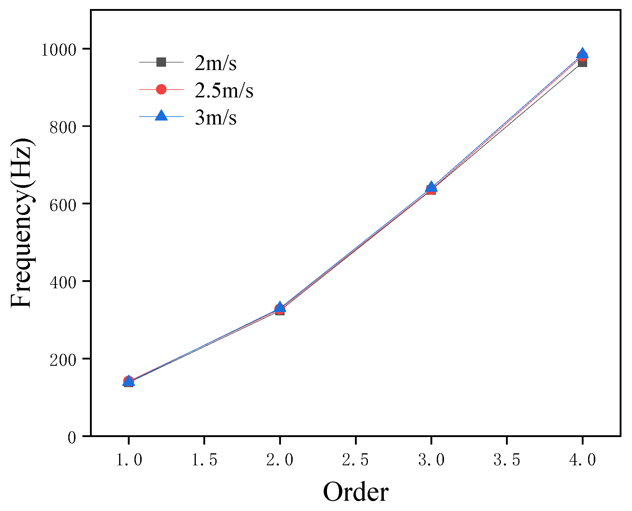
The performance of a piping system is closely linked to the fluid flowing through it. In certain applications, while the fluid type and pump remain unchanged, flow rate adjustments are often required to meet varying operational demands. However, altering the flow rate inevitably affects the internal pressure of the pipeline, thereby impacting the system’s overall performance. Consequently, analyzing the influence of flow rate on pipeline performance is of critical importance. In this study, the finite element software ANSYS Workbench (2023) was employed to analyze the modal changes of the pipeline under different flow rates. As shown in Figure 2, the pipeline’s modal characteristics do not exhibit significant changes when subjected to flow rates of 2 m/s, 2.5 m/s, and 3 m/s. The magnitude of these variations is within approximately ±3%.
Considering the impact of grid partitioning on the modal characteristics of pipeline systems, we further analyze the influence of grid size on pipeline modal behavior to verify the accuracy of the aforementioned simulation. The fluid velocity inside the pipeline was set to 2 m/s, and simulations were performed on the pipeline system’s modes under grid sizes of 15 mm, 20 mm, 25 mm, and 30 mm. The simulation results are presented in Table 1.
According to the simulation results shown in Table 1, the smaller the grid, the larger the simulation results of the first three modes of the pipeline system, but the maximum error is only about 3%. The small error can ignore the influence of grid size on the simulation results.

3.2. Effect of the Number of Pipeline Circuits on the Modes

Given the limited space on marine installations, hydraulic piping systems cannot adopt the long, straight layout commonly used in oil and gas transmission scenarios. Instead, marine hydraulic systems typically employ a short-distance multi-loop configuration. However, altering the pipeline layout structure can affect its modal characteristics. To investigate the vibration characteristics of the piping system, this study first analyzes the relationship between its modal behavior and the number of pipeline loops. Using the finite element analysis software ANSYS Workbench, simulations were conducted to analyze the wet modal characteristics of single-loop, double-loop, and three-loop pipelines under the same flow rate. As shown in Figure 3, the results indicate that with an increase in the number of loops in the piping system, the first four orders of modal frequencies decrease and the higher the modal order, the greater the reduction. This finding provides favorable conditions for researching low-frequency vibrations in piping systems.

3.3. Influence of Support Layout on Piping System Vibration

Pipelines are typically secured to substrates using pipe clamps and similar fixtures to provide support. This not only fixes the pipelines in place but also helps dampen vibrations and restrict pipeline deformation at the support points. To improve the stability of the pipeline experimental system, simulations were conducted to analyze the impact of support layout on the pipeline system, with the goal of identifying a more rational configuration. As illustrated in Figure 4, the simulation focused on a 1 m straight pipeline equipped with five support points along its length from the inlet to the outlet. Pipeline vibration was analyzed by evaluating different support point combinations: two supports (Points 1–5), three supports (Points 1–3–5), four supports (Points 1–2–4–5), and all five supports. The aim of this analysis was to understand how these layout variations influence pipeline vibration.
As presented in Figure 5, the simulation results reveal that the pipeline’s maximum vibration displacement decreases as the number of support points increases and this decreasing trend is more marked when the number of supports is smaller. Regardless of the number of supports, the pipeline’s maximum vibration displacement consistently occurs between the two supports nearest to the input end. For configurations with four or five support points, the vibration curves exhibit little variation due to significant overlap in support point positions; however, these layouts still conform to the vibration observed in other support configurations. Therefore, to enhance the stability of the piping system, reinforcing the pipeline’s input end can effectively reduce its maximum vibration displacement.

4. The Construction of Pipeline System Experimental Platform and Pipeline Vibration Experimental Analysis

Taking into account the theoretical model and simulation analysis results, combined with the actual working conditions of the marine’s hydraulic pipeline system, an experimental platform is built to verify the results of theoretical and simulation analysis.

4.1. Piping System Test Bench Construction

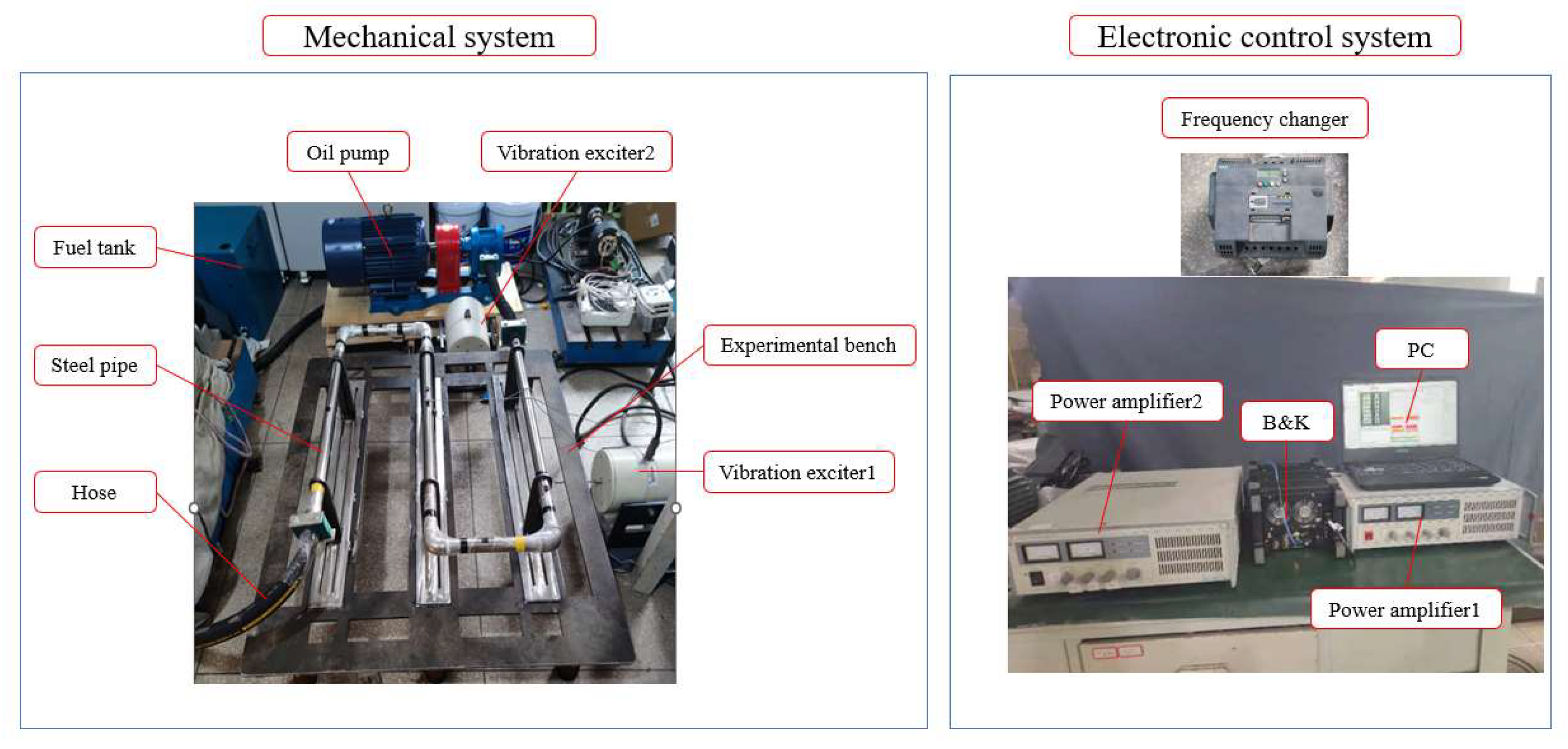
Based on the simulation analysis results and the spatial layout of the experimental bench, a piping system experimental bench (Figure 6) was designed and constructed. The experimental bench consists of two main parts: the mechanical system and the electronic control system. The mechanical system includes the base of the experimental bench, shaker 1, shaker 2, gear-type hydraulic oil pump, oil tank, steel pipelines (comprising three 0.8 m and two 0.25 m pipelines, as well as four pipeline joints), and hoses. The electronic control system comprises an inverter (SIEMENS sinamicsv20 11KW), power amplifiers 1 and 2, a host computer, and the B&K system (which includes acceleration sensors).

4.2. Experimental Analysis of Pipeline Vibration

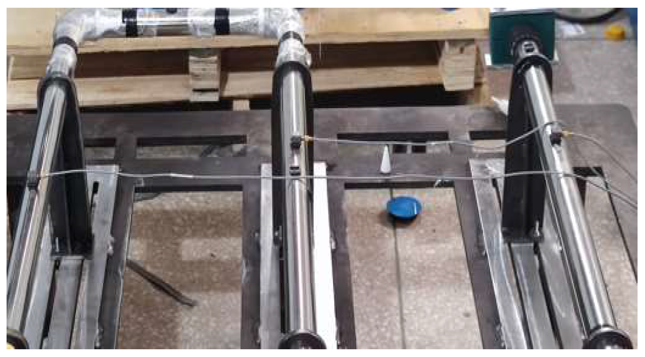
According to the experimental bench of the piping system, the effects of different fluid flow rates on the modal and vibration characteristics of the pipeline are firstly analyzed. In order to make the experimental results universal, the acceleration sensors are arranged as shown in Figure 7, and one acceleration sensor is arranged in the middle of each long straight pipeline of the three-loop piping system, and the sensor is fixed on the surface of the pipeline with glue through the base, and the data collected by the three acceleration sensors is averaged to describe the vibration situation of the pipeline, so as to make the experimental results more accurate.
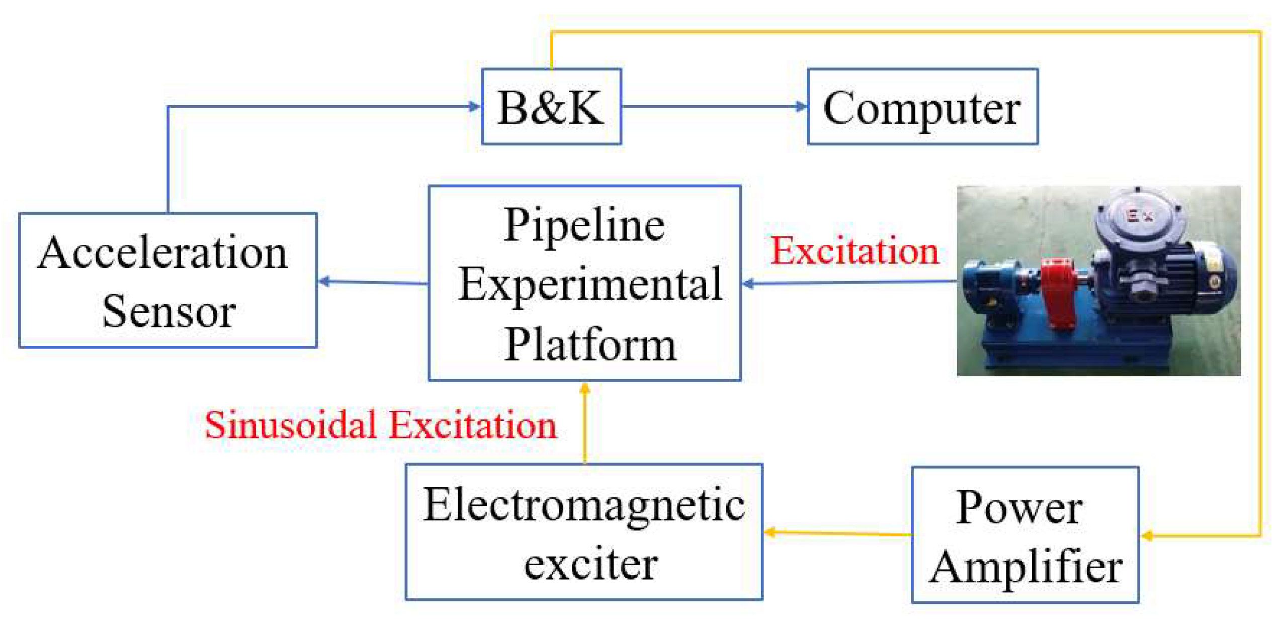
The experimental principle is shown in Figure 8. Firstly, according to the scheme mentioned earlier, the sensors are arranged, and the speed of the gear type hydraulic oil pump is set by a frequency converter to achieve three working states of hydraulic oil flow velocity distribution inside the pipeline: 2 m/s, 2.5 m/s, and 3 m/s. The time response data of the pipeline is collected by the B&K system through the sensors under three working conditions. Then, the collected data is Fourier transformed by MATLAB (R2018b) software to obtain the vibration amplitude frequency curves of the pipeline at three flow velocities. The results are shown in Figure 9 and Figure 10.
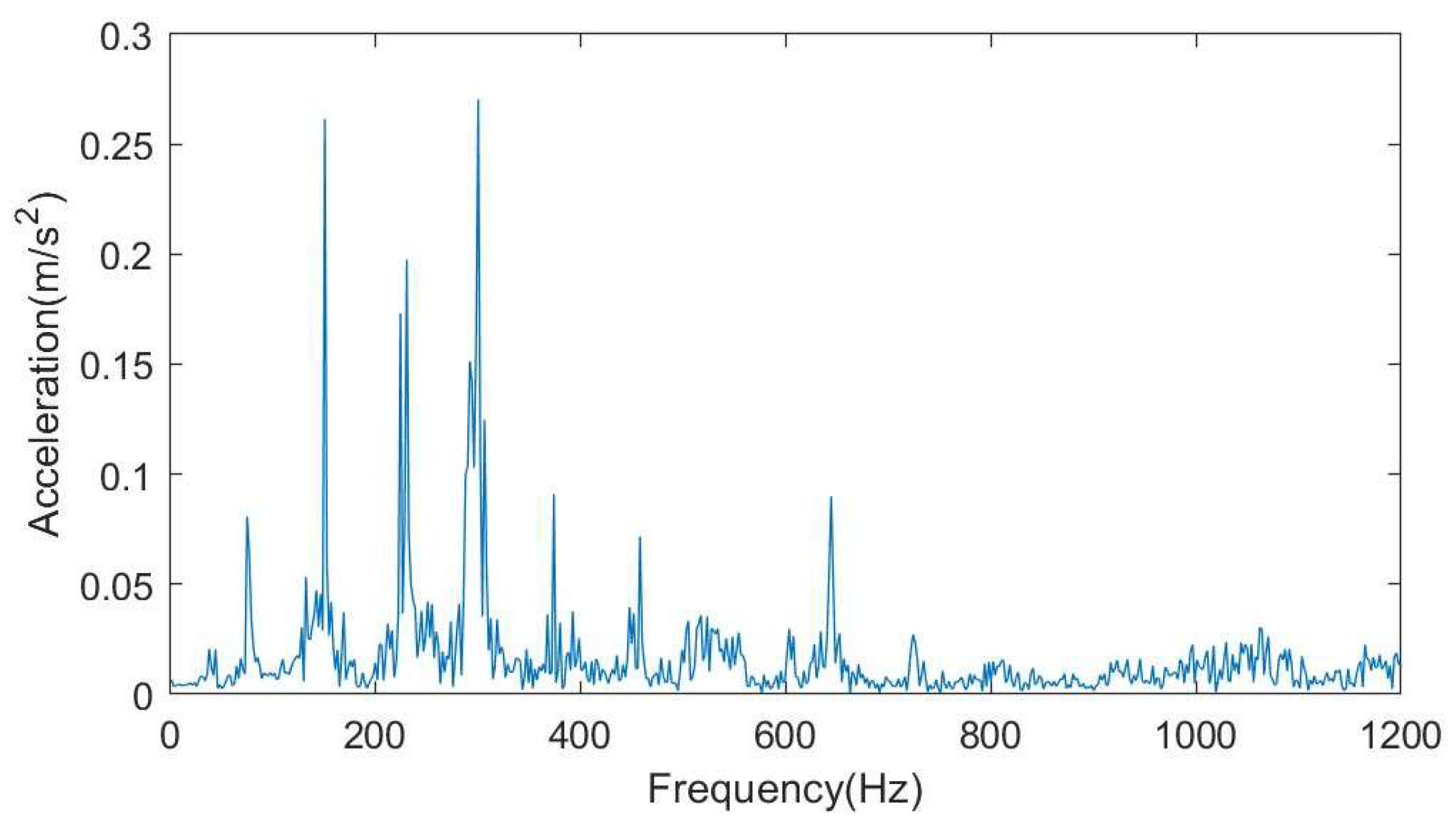
Figure 9 shows the vibration amplitude-frequency curve of the pipeline at a flow velocity of 2 m/s. The actual modal characteristics of the pipeline can be determined by identifying the resonance peaks on the curve. However, due to the complexity of the working environment during the experiment, the vibration of the entire mechanical system was detected as a whole, resulting in multiple resonance peaks on the vibration curve. Analysis of the frequencies corresponding to these peaks reveals that in addition to the resonance peaks caused by the pipeline’s modal characteristics, additional resonance peaks are generated by the experimental platform base, soft tube, and hydraulic pump base at their respective natural frequencies. After eliminating the influence of these interfering factors, the first three modal frequencies of the piping system were determined to be 151.5 Hz, 311.9 Hz, and 644.8 Hz. These values exhibit an error of 10% or less compared with the simulation results (150.2 Hz, 301.7 Hz, 622.4 Hz), thus verifying the validity of the theoretical simulation. Furthermore, when compared with the first three modal frequencies of aviation pipelines reported in Reference [31], the error is relatively small approximately 15% which can be attributed to differences in application environments. This further confirms the accuracy of both the experiment and theoretical simulation.
The three curves in Figure 10 show the vibration amplitude-frequency curves of the pipeline under fluid flow rates of 2 m/s, 2.5 m/s, and 3 m/s, respectively. It can be observed that the pipeline’s vibration amplitude increases as the fluid flow rate inside the pipeline increases, indicating a more intense vibration of the piping system. When compared with Figure 8, the resonance peaks in the two figures show no significant shift and remain essentially unchanged, this also indicates that changes in flow rate have no significant effect on the modal characteristics of the piping system, which is consistent with the results of the previous simulation.
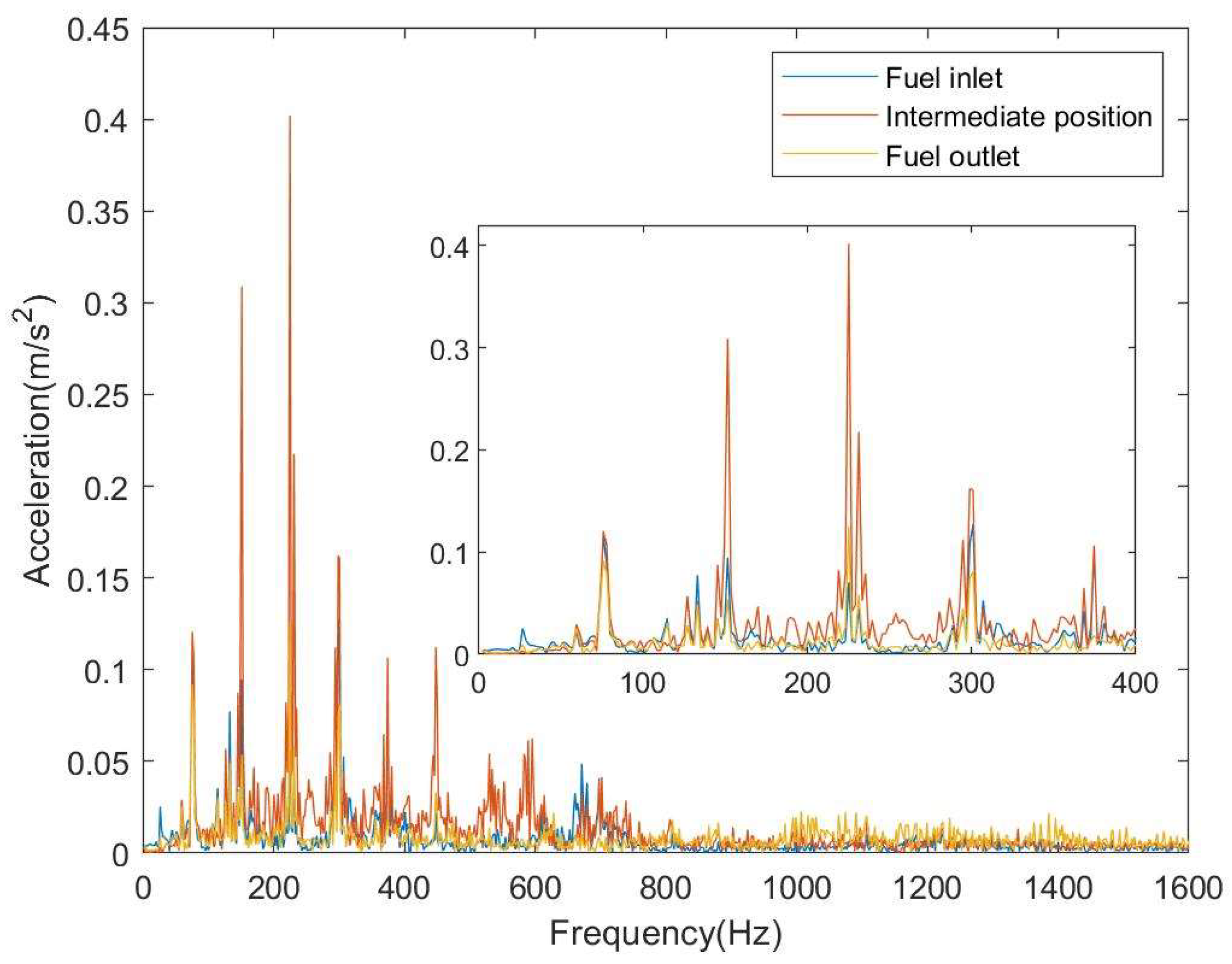
Given that it is difficult to conduct experiments under varied support conditions once the pipeline experimental platform is constructed, this study mounted three acceleration sensors at the input end, output end (both at the support locations), and midpoint of a straight pipeline to analyze the pipeline’s vibration distribution during fluid flow. As shown in Figure 11, the experimental results indicate that due to support constraints, the pipeline exhibits less vibration at the input and output ends, whereas vibration at the midpoint of the cantilevered pipeline increases significantly. This confirms that increasing the number of supports in the piping system can reduce the pipeline’s overall vibration level.
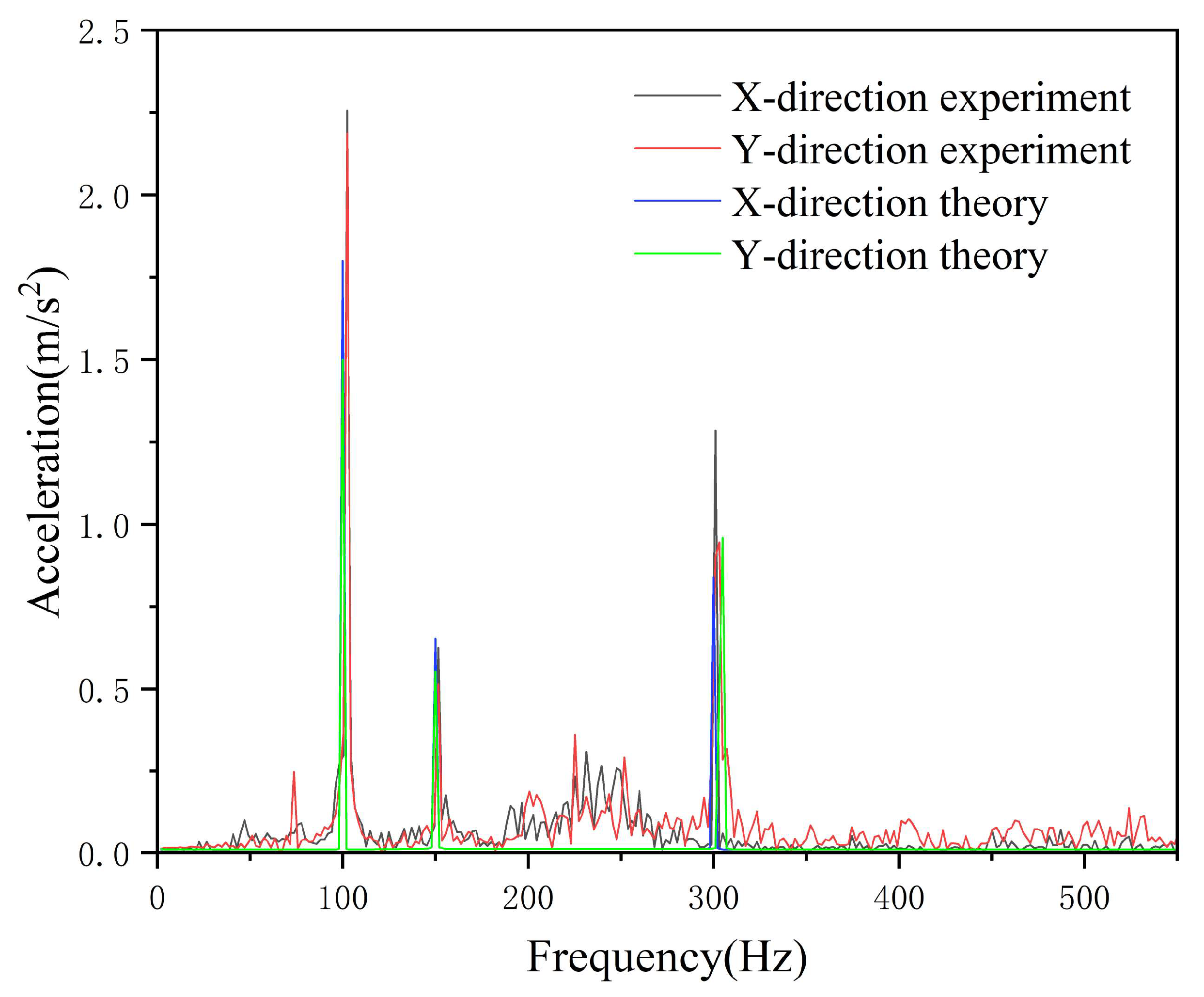
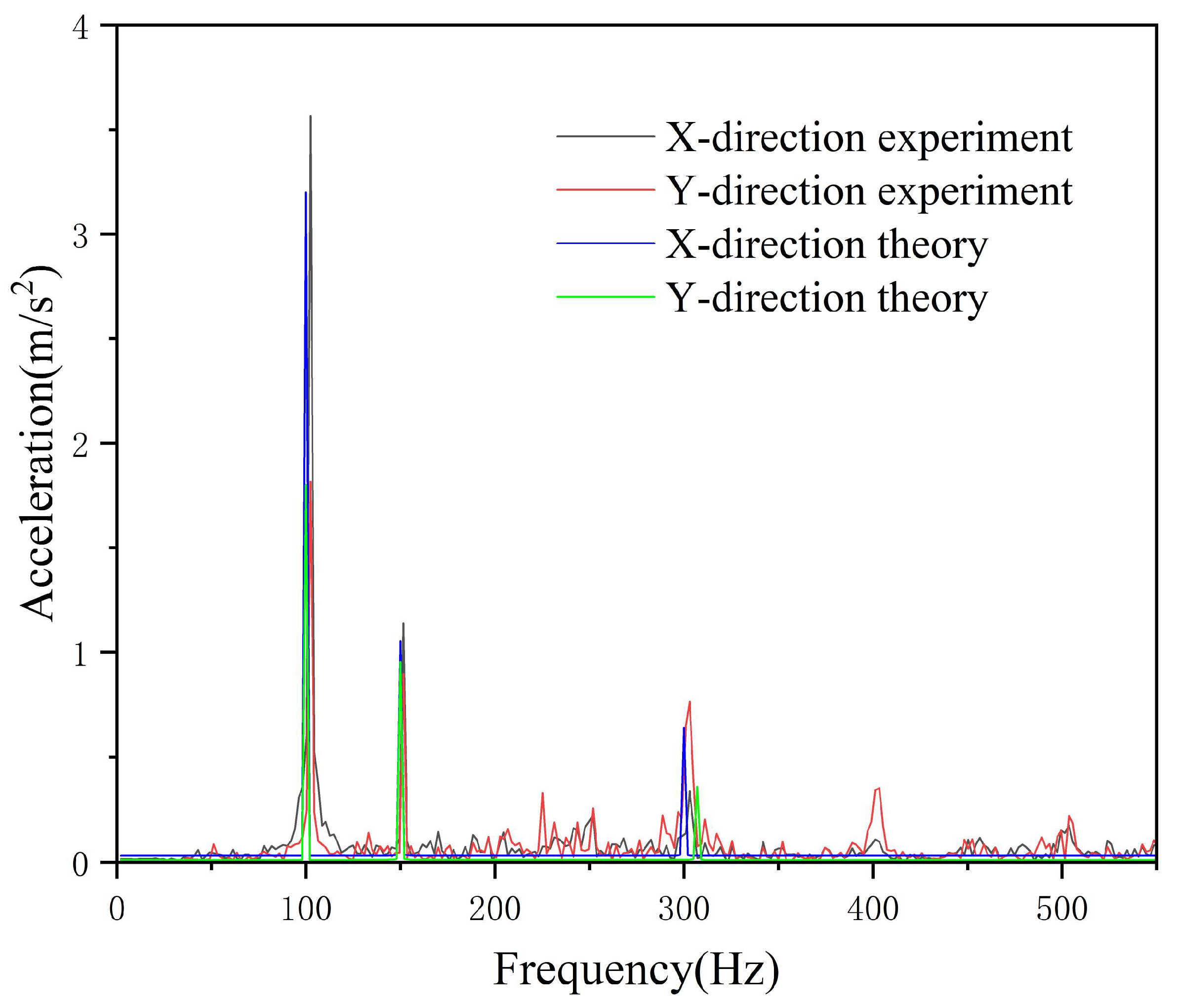
Marine vessels operate in the ocean and are subject to complex marine environments. In addition to vibrations caused by fluid flow, the on-board hydraulic pipeline systems are also affected by various external vibrations including vibrations from transmission equipment, wave impacts on the hull, and the effects of marine organisms on the hull, all of which influence the pipeline’s vibration characteristics. Therefore, when analyzing hydraulic pipeline systems installed on marine vessels, not only should their intrinsic vibrations be considered, but also the impact of external interference. This study uses an electromagnetic shaker to simulate external interference and analyzes the influence of the external environment on pipeline vibration characteristics through sinusoidal excitations applied in different directions. Specifically: An accelerometer was attached to the pipeline parallel to the surface of the experimental platform base to measure vibrations in the X-direction; Another accelerometer was attached to the pipeline perpendicular to the platform base surface to measure vibrations in the Y-direction. A 100 Hz sinusoidal interference signal was generated by the electromagnetic shaker, and pipeline vibration characteristics were analyzed under three conditions: unidirectional axial interference, unidirectional radial interference, and simultaneous unidirectional axial and radial excitation. The experimental principle is schematically illustrated by the yellow line in Figure 8. The electromagnetic shaker was controlled using a B&K system and power amplifier to apply a sinusoidal excitation force to the pipeline experimental platform. Vibrations were then measured via the accelerometers; finally, the collected time-domain response signals were converted using FFT (Fast Fourier Transform) in MATLAB (R2018b) software to obtain the vibration amplitude-frequency curves of the pipeline under external excitation. Comparisons between the experimental results and theoretical numerical analysis results are presented in Figure 12, Figure 13, Figure 14 and Figure 15.
Figure 12, Figure 13, Figure 14 and Figure 15 present comparisons between experimental results and theoretical analysis outcomes under four conditions: no excitation, axial excitation, radial excitation, and combined axial-radial dual excitation. From the positions of experimental and theoretical resonance peaks in these figures, it is evident that the introduction of external excitation has no effect on the modal characteristics of the experimental platform, its first and second modal frequencies remain around 150 Hz and 310 Hz, respectively. Figure 12 shows the comparison between experimental and theoretical results without excitation. Due to external interference, the acceleration amplitude measured in the experiment is relatively large, particularly with a prominent resonance peak appearing near the 150 Hz resonance frequency. At this point, the discrepancy between experimental and theoretical results is significant. After applying a 100 Hz sinusoidal excitation to the axial direction of the experimental platform, Figure 13 clearly shows that the vibration curve exhibits a distinct peak at the same frequency, with the detected acceleration increasing by 2–3 m/s2 compared to the unexcited condition—indicating that the piping system has undergone resonance. The application of axial excitation significantly enhances the amplitude in both X and Y directions; the maximum vibration acceleration outside the resonance region is nearly doubled, reaching approximately 0.5 m/s2. As shown in Figure 14, the application of sinusoidal excitation in the radial (X-direction) increases the amplitude in the X-direction for both experimental and theoretical results, demonstrating that external excitation applied in a specific direction directly affects vibration outcomes in that direction. However, compared to the amplitude enhancement in the X-direction, radial (X-direction) excitation has a smaller impact on the Y-direction amplitude, and even exerts a certain damping effect at higher frequencies. Figure 15 shows that when axial and radial excitations are applied simultaneously, the pipeline’s vibration curve combines the characteristics of the two individual excitation conditions. Vibrations in both X and Y directions are somewhat enhanced, but still only reach approximately 60% of the amplitude observed under axial excitation alone—consistent with theoretical analysis results. Reference [32] analyzes the fluid–structure interaction characteristics of straight pipelines by measuring vibration levels via pipeline wall displacement. It concludes that both axial and radial additional excitations significantly affect pipeline vibration at lower frequencies (especially below 400 Hz), with the vibration trend gradually slowing as frequency increases—consistent with the experimental results obtained in this study.

5. Conclusions

This paper focuses on the hydraulic system of marine vessels, with particular attention to three-loop hydraulic pipelines. It first derives the vibration equation of hydraulic pipelines under external excitation conditions (e.g., wave loads) encountered during offshore operations. To investigate the effects of multiple factors, including fluid flow rate, pipeline support layout, pipeline loop configuration, and external excitations in the service environment—on the modal and vibration characteristics of the pipeline system, the study employs fluid–structure interaction simulation and experimental validation.
  • The fluid flow rate change in the pipeline has no significant effect on the modal order of the overall piping system; however, the pipeline’s vibration intensity increases with increasing flow rate. Furthermore, the pipeline loop configuration exerts a more significant influence on the system’s modal order—increasing the number of loops can effectively reduce the modal order. Additionally, as the distance from the fluid inlet increases, the vibration amplitude of each pipeline span gradually decreases.
  • Increasing the number of supports can effectively reduce the overall vibration level of the piping system. It has been observed that the maximum vibration of the piping is concentrated between two supports located near the input end. Therefore, reinforcing the input end of the piping can effectively mitigate the amplitude of the maximum vibration.
  • The vibration characteristics of a piping system are influenced by external excitation. Specifically, when unidirectional excitation is applied, it enhances vibration in the same direction while simultaneously weakening vibration in other directions. Bidirectional excitation further complicates the pipeline’s vibration behavior: the excitation signals from the two directions interact with each other, resulting in a degree of enhancement in pipeline vibration, but this enhancement is less pronounced than that observed under unidirectional excitation. Furthermore, the aforementioned weakening effect on non-target directions disappears, thereby achieving a certain damping effect. This finding offers a new insight for the subsequent exploration of vibration isolation techniques for marine hydraulic pipelines.

Author Contributions

X.M.: Laboratory bench construction Data Curation, Writing—Original Draft; C.S.: Conceptualization, Methodology, Investigation. All authors have read and agreed to the published version of the manuscript.

Funding

This study was funded by Professor Chunsheng Song from the National Natural Science Foundation of China with grant number 51879209.

Institutional Review Board Statement

Not applicable.

Informed Consent Statement

Not applicable.

Data Availability Statement

The data that were generated and analyzed in this paper are available from the corresponding author upon request.

Acknowledgments

The authors declare that they have no known competing financial interests or personal relationships that could have appeared to influence the work reported in this paper.

Conflicts of Interest

The authors declare no conflicts of interest.

References

  1. Ma, W.; Wang, X.; Wang, B.; Leong, E.-C.; Zhou, S.; Wang, B.; Wang, C. Torsional vibration of a pipeline pile in unsaturated cross-anisotropic soil based on the fractional viscoelastic model. Ocean Eng. 2024, 313, 119483. [Google Scholar] [CrossRef]
  2. Fabrizio, A.; Roberto, A.; Salvatore, B.O. Pipeline vibration attenuation through internal damping and optimal design of vibro-impact systems. Sci. Rep. 2023, 13, 6510. [Google Scholar]
  3. Aitken, M.J.; Allsop, A.L.; Bussell, G.D.; Winter, M. Archaeomagnetic intensity determination: A nineteenth century pottery kiln near Jordan, Ontario. Can. J. Earth Sci. 1987, 24, 2392–2395. [Google Scholar] [CrossRef]
  4. Liu, M.; Wang, Z.; Zhou, Z.; Qu, Y.; Yu, Z.; Wei, Q.; Lu, L. Vibration response of multi-span fluid-conveying pipeline with multiple accessories under complex boundary conditions. Eur. J. Mech./A Solids 2018, 72, 41–56. [Google Scholar]
  5. Beatty, M.F. Stress-Softening Effects in the Vibration of a Non-Gaussian Rubber Membrane. Math. Mech. Solids 2003, 8, 481–495. [Google Scholar] [CrossRef]
  6. Ashley, H.; Haviland, G. Bending vibrations of a pipeline line containing flowing fluid. J. Appl. Mech. 1950, 17, 229–232. [Google Scholar] [CrossRef]
  7. Johnson, R.O.; Stonekin, J.E.; Carley, T.G. The stability of simply supported tubes conveying in compressible fluid. J. Sound Vib. 1987, 117, 335–350. [Google Scholar] [CrossRef]
  8. Askarian, A.R.; Haddadpour, H.; Firouz-Abadi, R.D.; Abtahi, H. Nonlinear dynamics of extensible viscoelastic cantilevered pipelines conveying pulsatile flow with an end nozzle. Int. J. Non-Linear Mech. 2017, 91, 22–35. [Google Scholar]
  9. Li, B.; Gao, X.; Liu, Y.; Yue, Z. Stability analysis of fluid-solid coupled vibration in two-ended solidly supported flow pipeline. Mech. Des. Manuf. 2010, 2, 105–107. [Google Scholar]
  10. Cao, J.; Liu, Y.; Liu, W. Study on wavelet finite element method for vibration in the tube surface of a flow-conveying bend. Vib. Shock 2018, 37, 256–260. [Google Scholar]
  11. Zhu, H.; Wang, W.; Yin, X.; Gao, C. Coupled vibration of a functional gradient-fed pipeline based on a hierarchical model. Vib. Shock 2019, 38, 203–209+259. [Google Scholar]
  12. Liang, Z.-j.; Guo, C.-y.; Chun, Y. Research On Mechanism of Dynamic Evolution Vibration Characteristics of Horizontal 90° Elbow Flow Pattern. J. Press. Vessel Technol. 2023, 145, 031404. [Google Scholar] [CrossRef]
  13. Zhu, L.; Chen, C.; Jiang, Y. Simulation Analysis and Experimental Investigation on the Fluid–Structure Interaction Vibration Characteristics of Aircraft Liquid-Filled Pipelines under the Superimposed Impact of External Random Vibration and Internal Pulsating Pressure. Appl. Sci. 2024, 14, 8008. [Google Scholar] [CrossRef]
  14. Zhu, B.; Feng, J.Z.; Guo, Y.; Wang, Y.Q. Exact closed-form solution for buckling and free vibration of pipes conveying fluid with intermediate elastic supports. J. Sound Vib. 2025, 596, 118762. [Google Scholar] [CrossRef]
  15. Zarghami, F.; Vatankhah, R.; Hashemnia, K. Passive vibration control and stability analysis of fluid-conveying pipe with different boundary conditions under impact load employing optimized absorbers. Int. J. Dyn. Control 2025, 13, 60. [Google Scholar] [CrossRef]
  16. dos Reis, E.V.M.; Sphaier, L.A.; Nunes, L.C.S.; Alves, L.S.d.B. Dynamic response of free span pipelines via linear and nonlinear stability analyses. Ocean Eng. 2018, 163, 533–543. [Google Scholar] [CrossRef]
  17. Cao, Y.; Yan, G.; Lu, J.; Qi, W.; Zhao, T.; Yu, D.; Cai, L.; Li, Y.; Zhang, W. Vibration mitigation and dynamics of pipeline system with nonlinear soft clamp by a nonlinear energy sink. Int. J. Non-Linear Mech. 2025, 170, 104990. [Google Scholar] [CrossRef]
  18. Gong, S.; Xu, P.; Bao, S.; Zhong, W.; He, N.; Yan, H. Numerical modelling on dynamic behaviour of deepwater S-lay pipeline. Ocean Eng. 2014, 88, 393–408. [Google Scholar] [CrossRef]
  19. Arastoo, A.; Firooz, B.-N.; Zhu, W. Fractional-order control with second-order sliding mode algorithm and disturbance estimation for vibration suppression of marine riser. J. Frankl. Inst. 2021, 358, 6545–6565. [Google Scholar]
  20. Gaurav, S.; Adepu, K.; Sangram, R. Enhancing Structural Vibration Damping in Marine Machinery: A Comprehensive Numerical Investigation with Modal and Harmonic Analysis. Appl. Mech. Mater. 2024, 921, 39–56. [Google Scholar] [CrossRef]
  21. Park, M.-H.; Yeo, S.; Choi, J.-H.; Lee, W.-J. Review of noise and vibration reduction technologies in marine machinery: Operational insights and engineering experience. Appl. Ocean Res. 2024, 152, 104195. [Google Scholar] [CrossRef]
  22. Zhang, L.X.; Yang, K. Fluid-Structure Interaction Theory and Its Application; Science Press: Beijing, China, 2004; p. 3. [Google Scholar]
  23. Wang, C.-Y.; Sun, Z.-P.; Qin, M.; Xu, Y.-Q.; Lv, S.-Q.; Yi, M. Non-Markovian effect of the fractional damping environment and Newton’s second law of motion. Mod. Phys. Lett. B 2018, 32, 8. [Google Scholar] [CrossRef]
  24. Watzka, B.; Omarbakiyeva, Y.; Hahn, L.; Klein, P.; Krumphals, I.; Rubitzko, T. Wind as a context for Newton’s first and second law and force diagrams. Phys. Educ. 2025, 60, 015006. [Google Scholar] [CrossRef]
  25. Wilkinson, D.H. Acoustic and mechanical vibrations in liquid-filled pipelinework systems. In Proceedings of the BNES International Conference on Vibration in Nuclear Plant, Paper 8.5, Keswick, UK, 9–12 May 1978; pp. 863–878. [Google Scholar]
  26. Hutchinson, J.R. Shear Coefficients for Timoshenko Beam Theory. J. Appl. Mech. 2001, 68, 87–92. [Google Scholar] [CrossRef]
  27. Chen, W.; Wang, L.; Peng, Z. A magnetic control method for large-deformation vibration of cantilevered pipeline conveying fluid. Nonlinear Dyn. 2021, 105, 1459–1481. [Google Scholar] [CrossRef]
  28. Li, Y. Study on Vibration Noise and Characteristics of Piping System Considering Fluid-Solid Coupling. Ph.D. Thesis, Harbin Engineering University, Harbin, China, 2011. [Google Scholar]
  29. Gao, H. Modification of 14-Equation Model for Fluid-Structure Interaction and Vibration Characteristic Analysis of Hydraulic Pipeline. Master’s Thesis, Yanshan University, Qinhuangdao, China, 2021. [Google Scholar]
  30. Li, S. Dynamic Analysis of Fluid-Structure Interaction of Pipe Systems Conveying Fluid. Doctoral Dissertation, Harbin Engineering University, Harbin, China, 2015. [Google Scholar]
  31. Liu, Y.; Wei, J.; Du, H.; He, Z.; Yan, F. An Analysis of the Vibration Characteristics of an Aviation Hydraulic Pipeline with a Clamp. Aerospace 2023, 10, 900. [Google Scholar] [CrossRef]
  32. Wu, J. Research on Coupled Vibration and Sound Radiation of Space Pipeline and Shell; China Shipbuilding Research Institute: Wuxi, China, 2023. [Google Scholar]
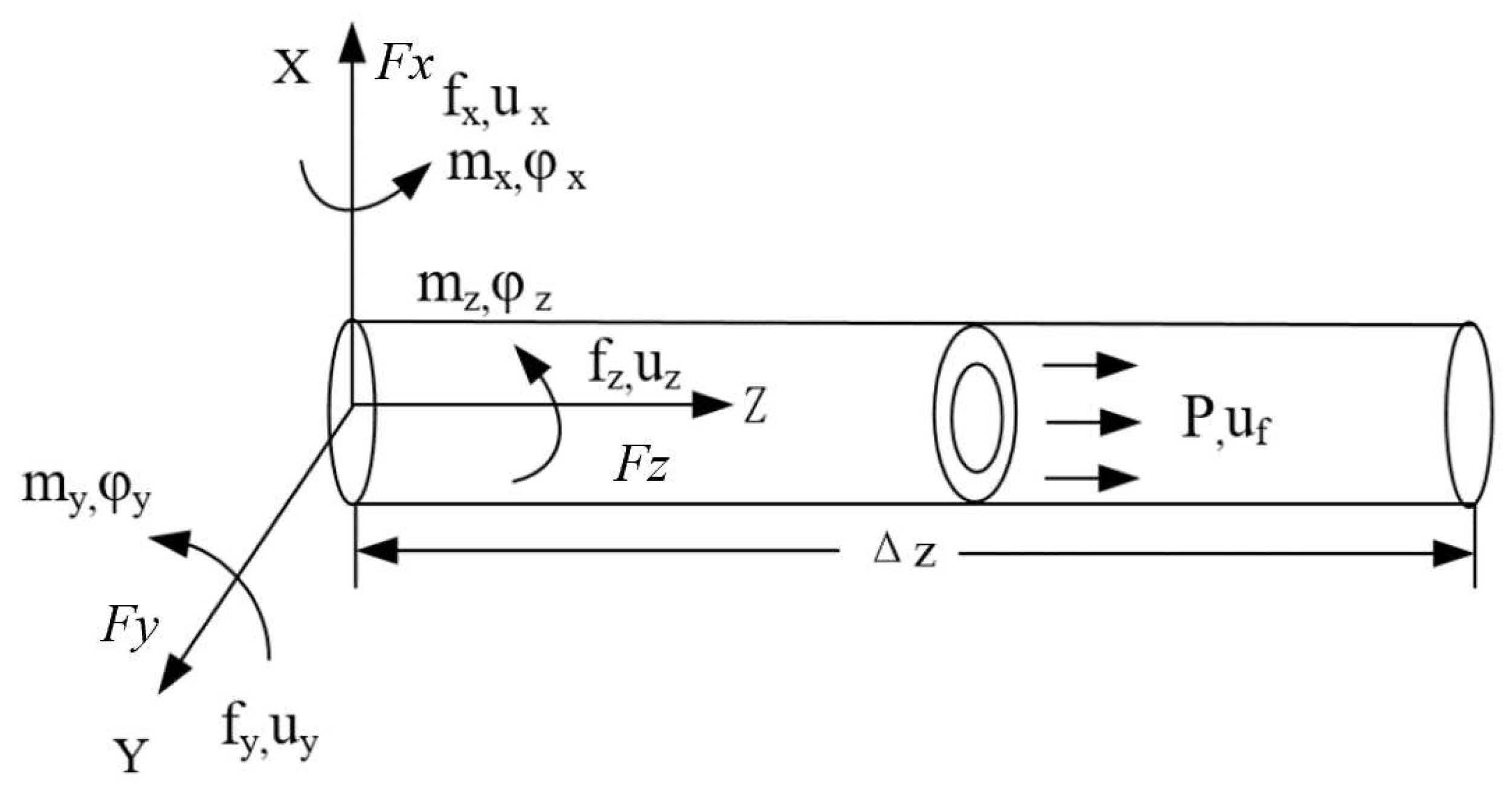
Figure 1. Force analysis of micro-elementary pipelines and fluids.
Machines 13 00859 g001
Figure 2. Modes of the three-loop piping system at different flow rates.
Machines 13 00859 g002
Figure 3. Modes of piping system under different circuits.
Machines 13 00859 g003
Figure 4. Layout of pipeline support points.
Machines 13 00859 g004
Figure 5. Vibration displacement curves of pipelines with different support layouts.
Machines 13 00859 g005
Figure 6. Layout of piping system experimental bench.
Machines 13 00859 g006
Figure 7. Acceleration sensor arrangement.
Machines 13 00859 g007
Figure 8. Experimental schematic diagram.
Machines 13 00859 g008
Figure 9. Amplitude-frequency curve of pipeline vibration at 2 m/s.
Machines 13 00859 g009
Figure 10. Amplitude-frequency curves of pipeline vibration at different flow rates.
Machines 13 00859 g010
Figure 11. Amplitude-frequency curves of pipeline vibration at different locations.
Machines 13 00859 g011
Figure 12. Amplitude-frequency curve of undisturbed pipeline vibration.
Machines 13 00859 g012
Figure 13. Amplitude-frequency curve of pipeline vibration during axial interference.
Machines 13 00859 g013
Figure 14. Amplitude-frequency curve of pipeline vibration during radial interference.
Machines 13 00859 g014
Figure 15. Amplitude-frequency curves of pipeline vibration during axial and radial disturbances.
Machines 13 00859 g015
Table 1. Modal simulation results under different grid divisions.
Grid Size/mmFirst Order/HzSecond Order/HzThird Order/Hz
15151.4307.5638.1
20150.2301.7622.4
25149.7300.2617.5
30147.5298.6611.9
Disclaimer/Publisher’s Note: The statements, opinions and data contained in all publications are solely those of the individual author(s) and contributor(s) and not of MDPI and/or the editor(s). MDPI and/or the editor(s) disclaim responsibility for any injury to people or property resulting from any ideas, methods, instructions or products referred to in the content.