Article

Ultra-Long, Minor-Diameter, Untethered Growing Continuum Robot via Tip Actuation and Steering

1
Zhejiang Key Laboratory of Intelligent Construction and Operation & Maintenance for Deep-Sea Foundations, Ningbo University of Technology, Ningbo 315211, China
2
Ningbo Key Laboratory of Micro-Nano Motion and Intelligent Control, Ningbo University, Ningbo 315211, China
3
Parallel Robot and Mechatronic System Laboratory of Hebei Province, Yanshan University, Qinhuangdao 066004, China
*
Author to whom correspondence should be addressed.
Machines 2025, 13(9), 851; https://doi.org/10.3390/machines13090851
Submission received: 5 August 2025 / Revised: 3 September 2025 / Accepted: 7 September 2025 / Published: 15 September 2025
(This article belongs to the Special Issue Advances and Challenges in Robotic Manipulation)

Abstract

Continuum robots with outstanding compliance, dexterity, and lean bodies are successfully applied in medicine, aerospace engineering, the nuclear industry, rescue operations, construction, service, and manipulation. However, the inherent low stiffness characteristics of continuum bodies make it challenging to develop ultra-long and small-diameter continuum robots. To address this size–scale challenge of continuum robots, we developed an 8 m long continuum robot with a diameter of 23 mm by a tip actuation and growth mechanism. Meanwhile, we also realized the untethered design of the continuum robot, which greatly increased its usable space range, portability, and mobility. Demonstration experiments prove that the developed growing continuum robot has good flexibility and manipulability, as well as the ability to cross obstacles and search for targets. Its continuum body can transport liquids over long distances, providing water, medicine, and other rescue items for trapped individuals. The functionality of an untethered growing continuum robot (UGCR) can be expanded by installing multiple tools, such as a grasping tool at its tip to pick up objects in deep wells, pits, and other scenarios. In addition, we established a static model to predict the deformation of UGCR, and the prediction error of its tip position was within 2.6% of its length. We verified the motion performance of the continuum robot through a series of tests involving workspace, disturbance resistance, collision with obstacles, and load performance, thus proving its good anti-interference ability and collision stability. The main contribution of this work is to provide a technical reference for the development of ultra-long continuum robots based on the tip actuation and steering principle.

1. Introduction

Thanks to their outstanding compliance, dexterity, and lean bodies, continuum robots achieve a long reach through narrow and tortuous environments, enabling currently unachievable tasks for medical, aerospace, nuclear, rescue, construction, service, and manipulation applications to be achieved [1,2,3,4,5,6,7]. Scaling continuum robots up or down is a fundamental step toward providing a credible alternative to traditional rigid-bodied robots. Most existing continuum robots have body sizes mostly ranging from millimeters [8,9] to meters [10]. Increasing the length of a continuum robot and reducing its diameter is beneficial for expanding its workspace and improving its ability to pass through narrow environments. However, due to the inherent low stiffness characteristics of continuum robots, the development of ultra-long and minor-diameter continuum robots has always been a challenge. Currently, lightweight design and new shape control mechanisms are two promising approaches to addressing this challenge.
To solve the lightweight design problem, some researchers have attempted to develop continuum robots by using inflatable membrane structures [11,12,13], origami structures [14,15,16], and a combination of inflatable and origami structures [17,18,19]. For example, Oh and Rodrigue [20] developed an inflatable robotic arm with a length of nearly 5 m and a diameter of 40 cm, and Alvarez Palacio et al. [21] developed a long-range inflatable arm with a length of nearly 10 m and a diameter of 30 cm. Similarly, low-density 3D-printed structures [22], modular morphing lattices [23], and tapered tensegrity [24] are also the most promising choices for developing lightweight continuum robots. For example, Rubio et al. [23] developed a large-scale underwater continuum robot based on a 3D architecture, which is 1.5 m long and has an envelope diameter of 167 mm. In addition, using actuation technologies such as muscle fibers [25], dielectric elastomers [26,27], and magnetic fields [28,29] to develop continuum robots can also enable their lightweight design.
Ultra-long continuum robots can also be enabled by new shape control mechanisms, of which the growing continuum robot is a typical representative [30,31]. The elongation and direction control of the growing continuum robot can be realized by a variety of mechanisms, such as pressure-triggering mechanisms [32,33,34], pitch-up motion mechanisms [35], and tip expansion mechanisms [36]. The main reason that the growing robot can achieve an ultra-long reach is that it can use its surroundings to provide support for itself, effectively compensating for low stiffness. Compared to a lightweight design, the growing mechanism enables the development of longer and more compact continuum robots. For example, the vine-like soft robots developed by Li et al. [37], Coad et al. [38], and Hawkes et al. [39] have lengths of 5 m, 6 m, and 72 m, with diameters of 76.4 mm, 70 mm, and 25 mm, respectively. In addition, Yamaguchi et al. [40] developed a long continuum robot (3.6 m in length and 48 mm in diameter) based on the water jet mechanism, which has potential applications in water environments and firefighting.
To tackle the challenge of developing ultra-long and minor-diameter continuum robots, we designed an untethered growing continuum robot (UGCR), based on tip actuation and steering, and developed a prototype with a length of 8 m and a diameter of 23 mm. Compared with inflatable continuum robots, the UGCR has a smaller diameter and a more compact structure, which enables extension and retraction by a growing mechanism. Existing growing robots are good at creating 3D structures along the path of movement, but their real-time motion ability is weak. The growing continuum robot developed here can enable real-time movement in the workspace by controlling the magnitude and direction of the tip actuation force. In addition, the untethered design of large-scale continuum and soft robots is also a challenge in the field of robotics [41]. The UGCR adopts a rigid–flexible hybrid structure, where the tip actuation and steering, as well as the extension and retraction of the continuum body, are enabled by rigid motors, resulting in the development of an untethered prototype.
In this paper, we first present the principle of controlling the shape and direction of the UGCR via tip actuation and steering. Second, we provide a series of demonstration experiments, including obstacle avoidance, target search, human–machine interaction, liquid conveying, and target picking, which verify its flexibility and dexterity. Finally, we test the motion performance of the continuum robot, including workspace, disturbance resistance, collision with obstacles, and load performance through parameter measurements. The main contribution of this work is to provide a technical reference for the development of ultra-long continuum robots based on tip actuation and steering.

2. Design and Fabrication

The design of an UGCR needs to address the control of the length, shape, and direction of its continuum body. As shown in Figure 1a, the length of an UGCR is controlled by forward and reverse rotations of a winch. Due to the low stiffness and large length of the continuum body, the UGCR mainly grows in the direction of gravity. The shape of the UGCR is determined by both its gravity and the driving force at its tip. As shown in Figure 1b, the direction of the continuum body can be controlled by changing the deflection direction of its tip actuator. The driving force of the deflected actuator can be decomposed into Fx and Fy, which can control the direction and shape of the continuum body, respectively. The growing motion of the UGCR can be enabled by cooperatively controlling the rotation of its winch, as well as the driving force and deflection direction of its tip actuator, as shown in Figure 1c. We use a ducted fan as the tip actuator and control the deflection direction of the ducted fan through a stepper motor.
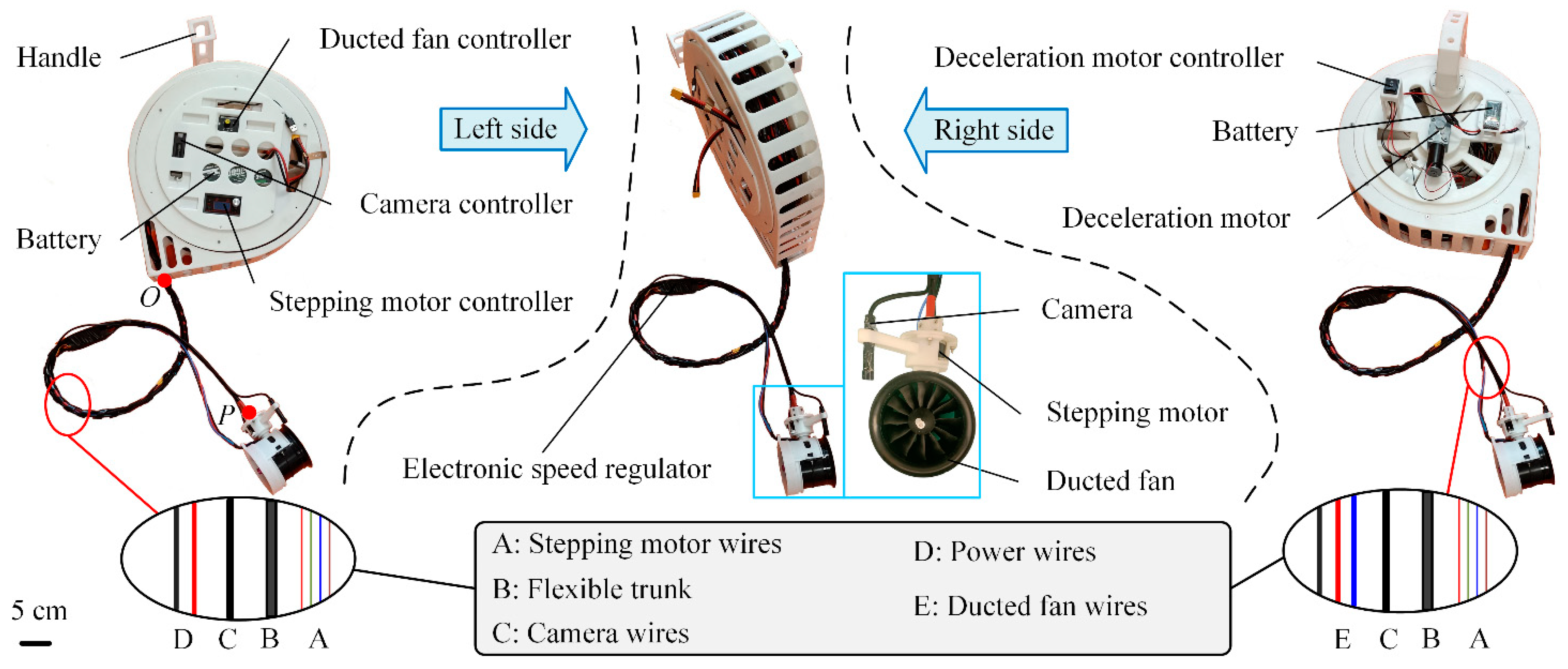
The prototype of the UGCR is shown in Figure 2. We employ a ducted fan (EDF-70-6S-2300KV, Hengtuo Innovation Technology Co., Ltd., Changzhou, China) as the tip actuator, and use a stepper motor (36HM2004A4-HM, Sumtor Wuxi Electric Equipment Co., Ltd., Dongguan, China) to control the deflection direction of the ducted fan. Meanwhile, an electronic speed regulator (80A, Hengtuo Innovation Technology Co., Ltd., Changzhou, China) is installed at the tip of the continuum body to control the speed of the ducted fan. The winch controlling the length of the UGCR is made of UV-cured resin (Somos Imagine 8000, Dutch State Mine, Chengdu Yixuan Model Co., Ltd., Chengdu, China) through 3D printing, and its forward and reverse rotations are controlled by a deceleration motor (5840-31ZY, Shenzhen Xinyongtai Motor Co., Ltd., Shenzhen, China). Furthermore, a camera is installed at the tip of the continuum body to guide the movement of the UGCR.
The continuum body consists of a flexible trunk, wires (including a stepper motor, camera, power, and ducted fan wires), and a spiral binding tube (made of industrial-grade PE plastic). The diameter of the continuum body is 23 mm. The flexible trunk, which has a diameter of 8 mm, is composed of a steel spring tube structure wrapped with rubber skin, which ensures it has good torsional resistance. As shown in Figure 2, the controller and battery (3S-800mAh-45C, Shenzhen Grepow Battery Co., Ltd., Shenzhen, China) of the deceleration motor are installed on the right side of the winch, while the controller and battery (6S-6000mAh-75C, Shenzhen Grepow Battery Co., Ltd., Shenzhen, China) of the ducted fan, stepper motor, and camera are installed on the left side of the winch. The total mass of the UGCR is 6.5 kg. The untethered hardware system enables the UGCR to move freely in a larger space.

3. Modeling

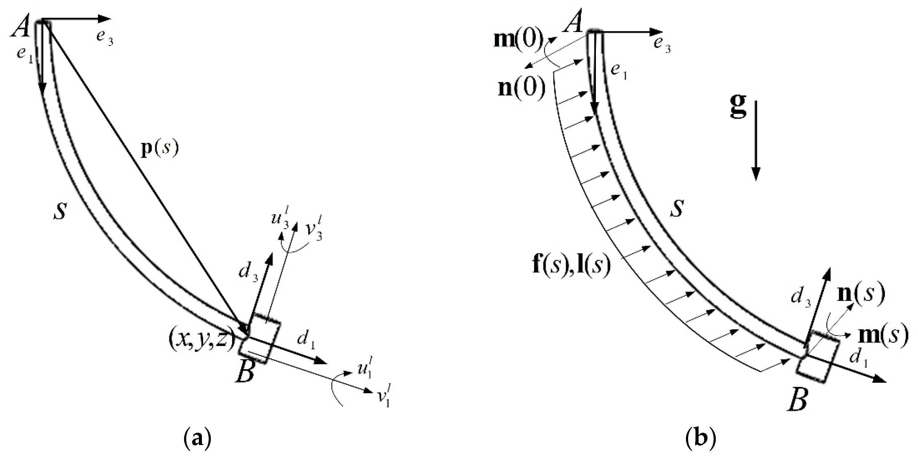
As shown in Figure 3a, the position p ( s ) of any point on the continuum body can be represented as follows:
p ( s ) = x ( s ) e 1 + y ( s ) e 2 + z ( s ) e 3
where x(s), y(s), and z(s) represent the position coordinates along the backbone direction of the continuum body at a length of s; e1, e2, e3 are the coordinate axes of the global coordinate system.
Taking the derivative of position p with respect to s yields the following:
p ˙ ( s ) = R ( s ) v l ( s )
where R(s) represents the rotation matrix of the local coordinate system relative to the global coordinate system at length s of the continuum body, and v l ( s ) represents the velocity vector in the local coordinate system at length s of the continuum body.
As shown in Figure 3b, the analysis of the force and moment on the continuum body shows the following:
n ( s ) n ( 0 ) + 0 s f ( s ) d s = 0
m ( s ) m ( 0 ) + p ( s ) × n ( s ) p ( 0 ) × n ( 0 ) + 0 s ( p ( s ) × f ( s ) ) d s + 0 s l ( s ) d s = 0
where n(s) represents the internal force acting on the continuum body at a length of s, while n(0) represents the internal force at the starting endpoint of the continuum body. Similarly, there exist internal moments m(s) and m(0). f(s) and l(s) denote the distributed forces and distributed moments acting on the continuum body at a length of s, respectively.
Then, taking a partial derivative according to s yields the following:
n ˙ ( s ) + f ( s ) = 0
m ˙ ( s ) + p ˙ ( s ) × n ( s ) + l ( s ) = 0
Linearly mapping kinematic variables to mechanical parameters can be expressed as follows:
n ( s ) = R ( s ) K n ( s ) ( v l ( s ) v l * ( s ) )
m ( s ) = R ( s ) K m ( s ) ( u l ( s ) u l * ( s ) )
where u l ( s ) represents the angular velocity vector in the local coordinate system at length s of the continuum body. v l * ( s ) and u l * ( s ) represent the velocity vector and angular velocity vector in the local coordinate system at length s of the continuum body before deformation. K n ( s ) = d i a g ( k n 1 k n 2 k a 1 ) , and K m = d i a g ( k m 1 k m 2 k b 1 ) . K n is the shear and tensile stiffness matrix, and K m is the bending and torsional stiffness matrix.
By substituting Equation (7) into Equation (5), the derivative of the velocity vector of the continuum body in the local coordinate system can be obtained:
v ˙ l = K n 1 ( R T f u ^ l K n ( v l v l * ) )
The partial derivative of the angular velocity vector with respect to s in a local coordinate system is solved as follows:
u ˙ l = K m 1 ( u ^ l K m ( u l u l * ) + v ^ l K n ( v l v l * ) + R T l )
The continuum body is considered to be neither compressed nor elongated; thus, the parameters when it is not deformed are as follows:
v l * = 1 0 0 T u l * = 0 0 0 T f = λ S e g e g = 1 0 0 T
where λ represents the weight per unit length of the continuum body, and S represents the length of the continuum body.
The boundary conditions for the static analysis of the continuum body can be expressed as follows:
p ( 0 ) = 0 0 0 T
R ( 0 ) = 1 0 0 0 1 0 0 0 1
n ( S ) = N ( S )
m ( S ) = M ( S )
where N ( S ) and M ( S ) represent the force and torque acting on the tip of the continuum body, respectively.
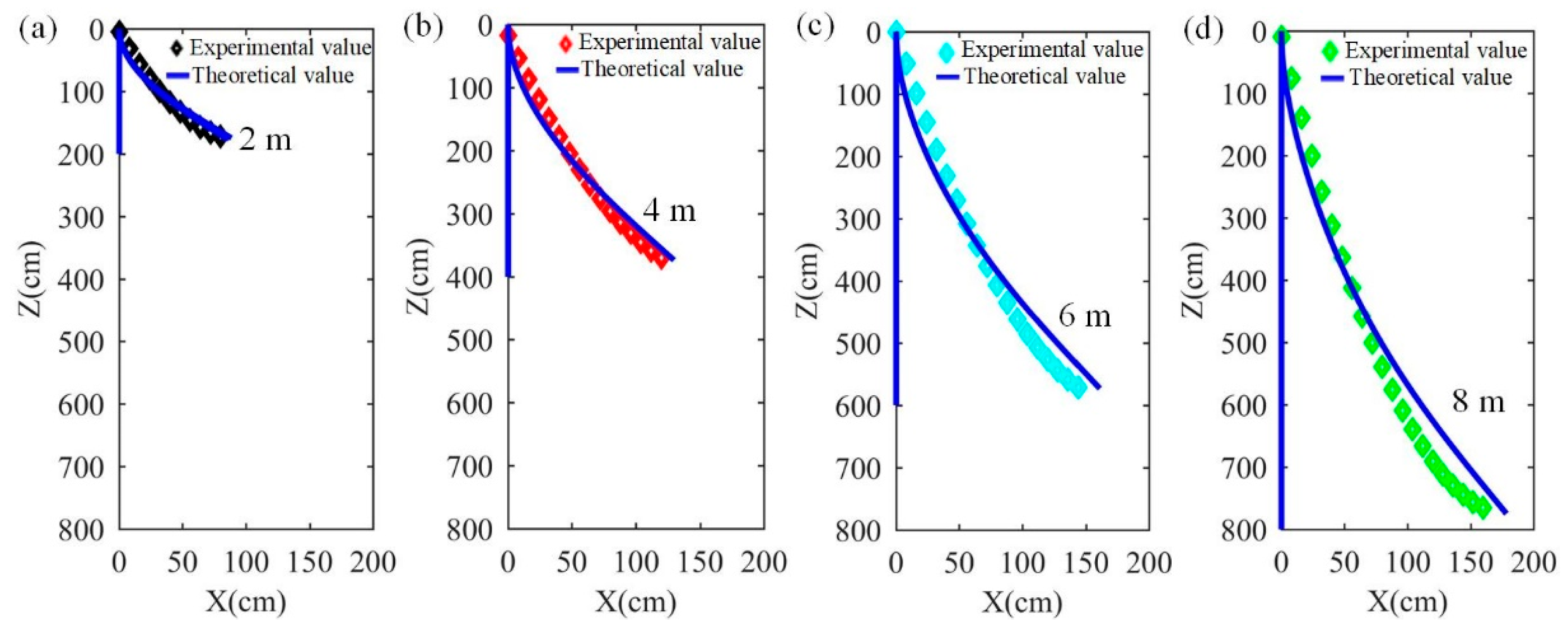
Further, we use the obtained static model to predict the deformation of the continuum body. We experimentally measured the tensile ( k a 1 = 1.1746 × 10 7   N ) and shear stiffness ( k n 1 = k n 2 = 4.518 × 10 6   N ), as well as the torsional ( k m 1 = k m 2 = 53.04   N m m 2 ) and bending stiffness ( k b 1 = 40.8   N m m 2 ) of the continuum body. The analysis results are compared with the experimental results of its maximum deformation, as shown in Figure 4. The prediction errors are within 1.9% (Figure 4a), 2.15% (Figure 4b), 2.33% (Figure 4c), and 2.6% (Figure 4d) when the lengths of the continuum body are 2 m, 4 m, 6 m, and 8 m, respectively. The prediction errors grow larger with the increase in the continuum body length due to the weight gain of the continuum body and the enhancement of its motion fluctuation. The primary sources of error in the static model arise from two aspects. First, the continuum body features a complex structure comprising a flexible trunk, wires, and a spiral binding tube. During modeling, we simplified it as a solid continuum body with uniform density, which constitutes a major source of error. Second, the deformation of the continuum body is also affected by factors such as gravity and environmental conditions (e.g., wind speed and temperature). These factors represent another significant source of error. Overall, the static model can be used to guide the structural design of the continuum body to a certain extent.

4. Results and Discussion

4.1. Manipulation Experiment

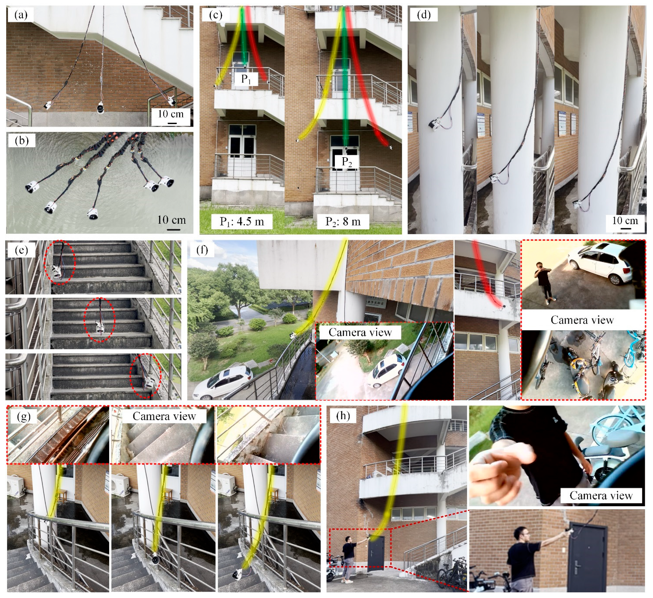
The manipulation experiment of the UGCR is shown in Figure 5 and Movie S1. The demonstration of shape and direction control confirms that the UGCR can move stably in the workspace (Figure 5a,b). As the continuum body grows (its maximum length is 8 m), the working space of the UGCR also increases (Figure 5c). Meanwhile, the growing mechanism allows the UGCR to reach deeper places for manipulation or exploration. The collaborative control of the length, shape, and direction of the continuum body enables complex movements of the UGCR, such as moving along a pillar like a vine (Figure 5d) and moving in approximately straight lines along steps (Figure 5e). The maximum movement speed of our proposed UGCR is 0.1 m/s, and its maximum positioning error is less than 20 mm.
A camera installed at the tip of the continuum body provides environmental images for operators, which can be used for target search and environmental navigation, as shown in Figure 5f. With the assistance of the camera, the UGCR can complete more complex tasks, such as flexibly crossing obstacles (Figure 5g) and searching for trapped people (Figure 5h). Similar to most continuum robots, the UGCR also has good human–machine interaction performance and can be in direct contact with humans, which has potential applications in human rescue, human–machine cooperation, and other aspects (Figure 5h).
However, the UGCR also has a limitation that it can only grow along the direction of gravity. On the one hand, this is because the driving force of its tip fan cannot fully overcome the gravity of its continuum body. On the other hand, the stiffness of the continuum body is relatively low, and gravity increases its motion stability when it grows along the direction of gravity. This limitation also determines that the UGCR is mainly used in scenarios with a height difference, such as deep wells, buildings, and gullies. However, this difficulty is not without a solution, which can be overcome by designing a more lightweight and variable-stiffness continuum body.
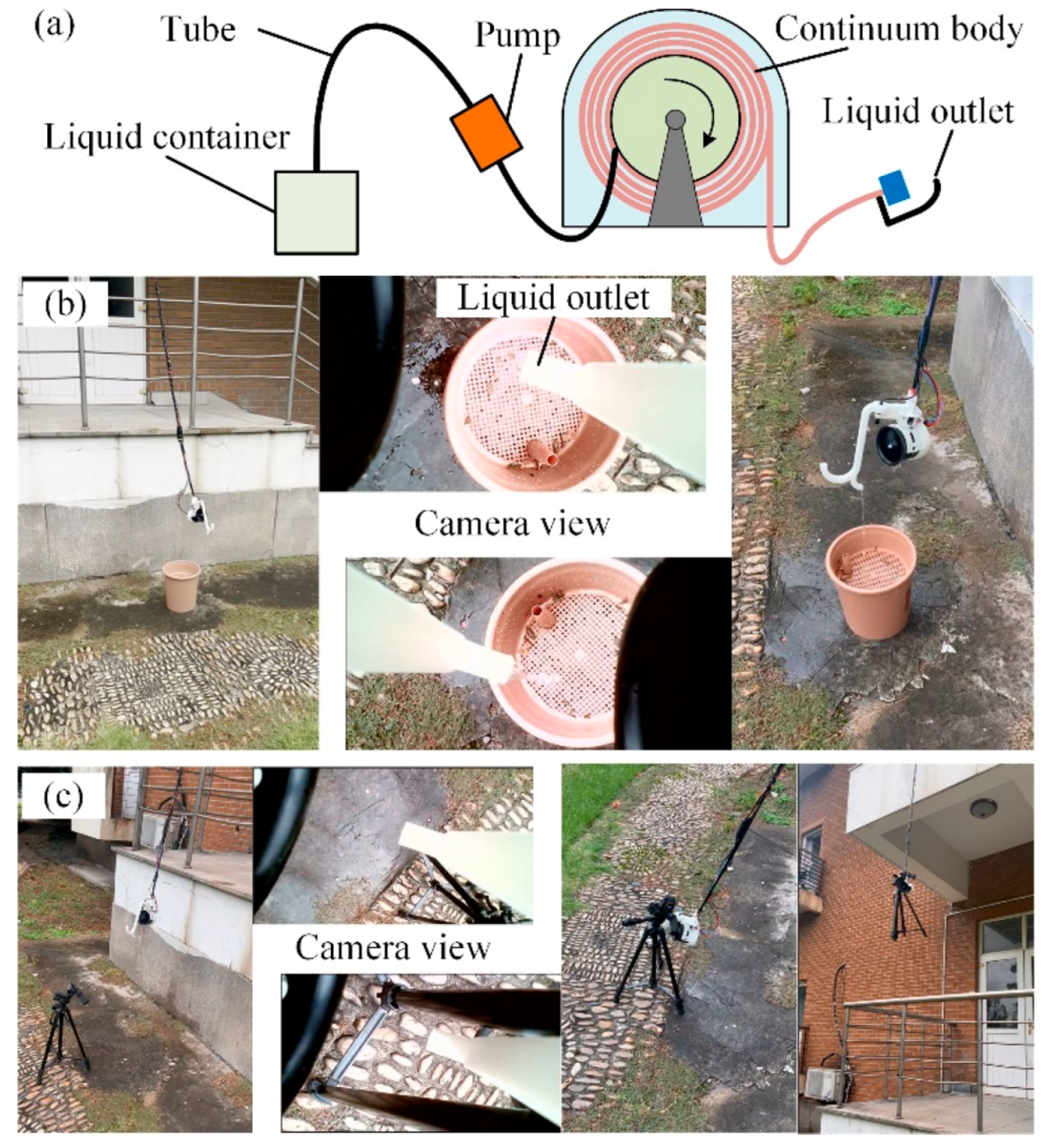
Long-distance transmission is one of the excellent performance characteristics pursued by continuum robots. Unlike existing continuum robots, the UGCR can deliver liquid to a target position over long distances, thanks to the hollow structure of its continuum body. As shown in Figure 6a, we connect a pump to one end of the continuum body (tied to the winch) and set up an outlet at the tip of the continuum body to form a liquid delivery system. By controlling the shape and direction of the UGCR, various liquids can be transported to designated positions through its continuum body, as shown in Figure 6b and Movie S2. The transportation of liquids increases the mass of the continuum body, thereby affecting the shape and tip position of the UGCR; however, it can be manually adjusted to the original position with the assistance of a camera. The liquid-conveying function of the UGCR has many potential applications, such as precise fire extinguishing and providing water, as well as medicine, for trapped people.
The functionality of the UGCR is closely related to its tip installation tools. As shown in Figure 6c, we installed a hook at the tip of the UGCR, which can be used to pick up objects in deep wells, pits, and other scenes. In addition, we can integrate multiple tools to enhance the versatility of the UGCR. For example, we combined an outlet pipe and a hook together at the tip of the UGCR to enable both liquid spraying and picking functions, as shown in Figure 6b,c.

4.2. Motion Performance

The deformation of continuum robots is highly nonlinear, and this phenomenon is more significant in ultra-long continuum robots, which causes great obstacles in their accurate modeling. To accurately and quickly obtain the motion range of the UGCR, we adopted a combination of analysis and measurement methods to determine its workspace, as shown in Figure 7a–c. The workspace here is the set of locations that can be reached by the tip point P of the UGCR (Figure 2), which is approximately cone-shaped. When the length of the UGCR is equal to 2 m, 4 m, 6 m, or 8 m, its maximum bending curves are as shown in Figure 7d, and the diameters of its reachable ranges are 160 cm, 244 cm, 312 cm, or 344 cm, respectively. It can be seen that the reachable range of the UGCR expands with the increase in its length; however, the ratio of the reachable radius increment to the length increment gradually decreases. This is mainly because the weight increase in the continuum body limits its motion range. In addition, the maximum bending curvature of the UGCR also becomes larger as the length of the continuum body increases.
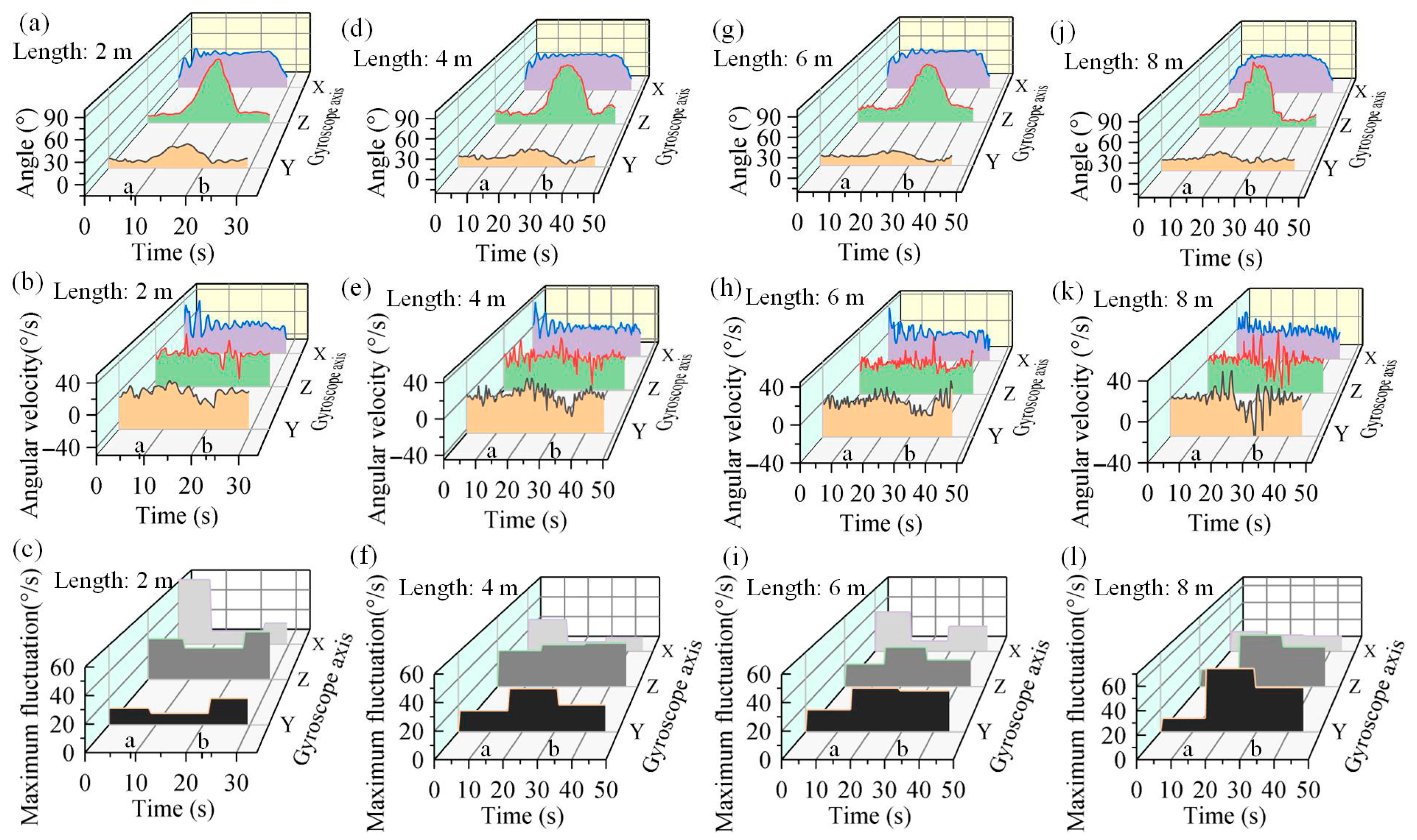
To test the motion performance of the UGCR with different lengths, a gyroscope is installed at its tip to measure its rotation angle and angular velocity during motion. During the testing process, the first step is to slowly increase the speed of the ducted fan, so the UGCR moves to its highest point. Then, while keeping the speed of the ducted fan constant, the stepper motor controls the UGCR to move to the far left and perform a reciprocating motion. Finally, the speed of the ducted fan is slowly reduced to return the UGCR to a resting state. The tip angle, angular velocity, and maximum fluctuation data of the UGCR during the testing process are shown in Figure 8. From the comparison of the maximum fluctuation data before time instant a and after time instant b, shown in Figure 8c,f,i,l, it can be observed that the fluctuations of the UGCR’s rotation about the Y and Z axes during the ducted fan speed increase (before time instant a) are smaller than those during the speed decrease (after time instant b), while the motion fluctuations in the X direction exhibit the opposite trend. When the stepper motor rotates to change the motion direction of the UGCR (from time instant a to b in Figure 8), a comparison of the maximum fluctuation data from time instants a to b, as shown in Figure 8c,f,i,l, reveals that the motion fluctuations of the UGCR generally increase with its length, especially in the Y and Z directions.
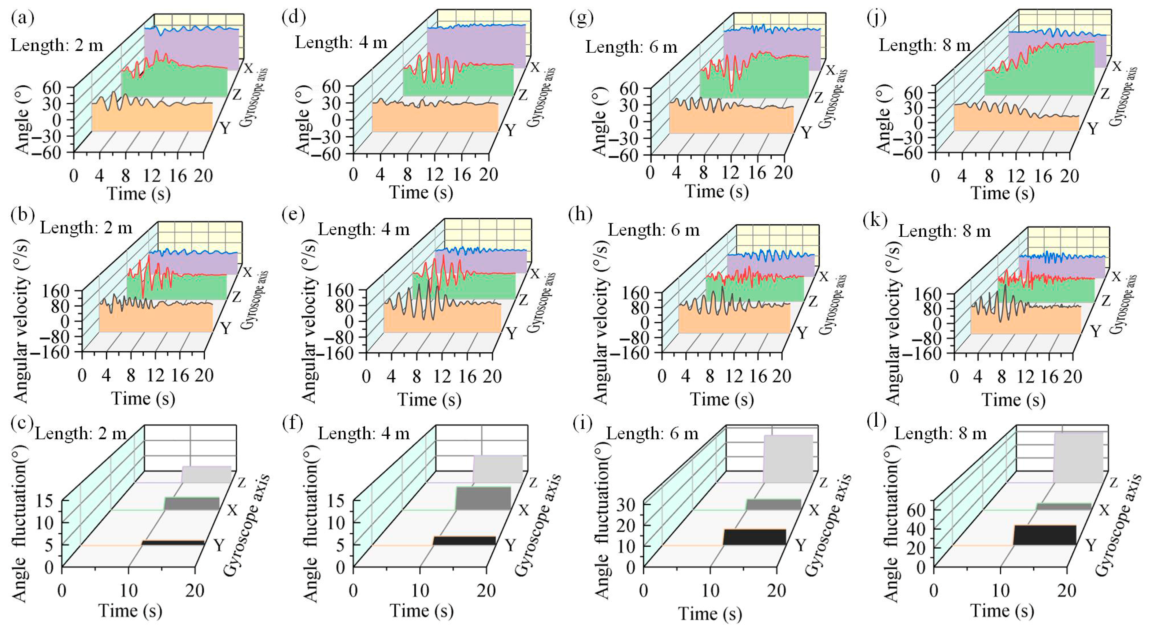
The motion characteristics of the UGCR are also tested when subjected to different interferences. First, a directional interference is observed as the stepper motor rotates forward and backward at an angle of 9° and a frequency of 2 Hz. The rotation angles, angular velocities, and angle fluctuation of the UGCR with different lengths under this interference are shown in Figure 9. It can be seen that when the continuum body length of the UGCR is small, such as 2 m (Figure 9a,b) or 4 m (Figure 9d,e), the fluctuations caused by this directional interference become larger with an increase in its continuum body length. However, as shown in Figure 9c,f, the angle fluctuations before and after interference are relatively small. After eliminating this interference (10 s later), it usually returns to a stable state before interference. When the continuum body length of the UGCR is relatively long, such as 6 m (Figure 9g,h) or 8 m (Figure 9j,k), the UGCR also returns to a stable state after eliminating the directional interference; however, there will be a deviation in the rotation angle compared to before being disturbed (Figure 9i,l).
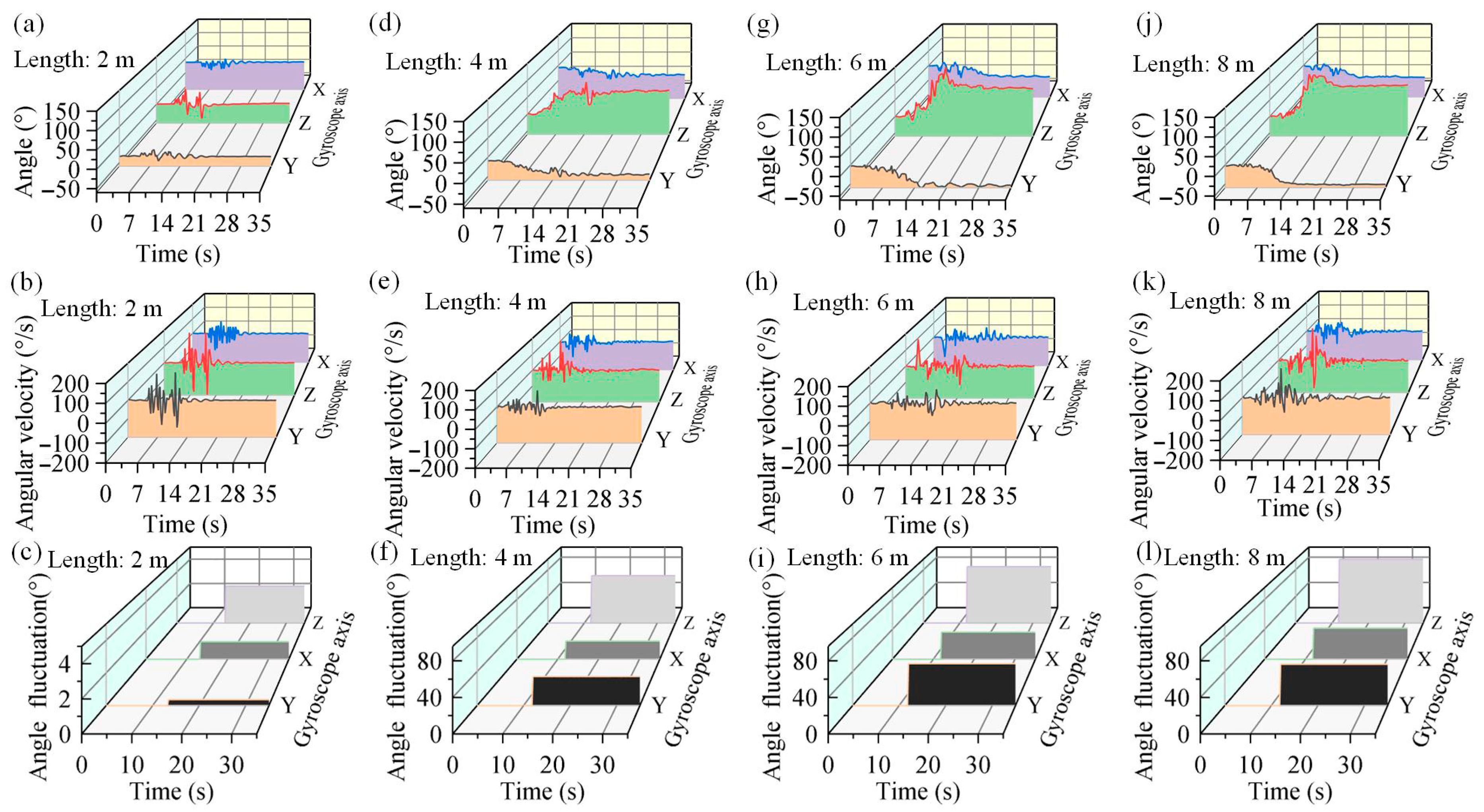
In addition, the UGCR is subjected to a periodic displacement interference of 10 cm in the direction of gravity with a load of 8 N at a frequency of 2 Hz. The rotation angles, angular velocities, and angle fluctuation of the UGCR with different lengths under this interference are shown in Figure 10. It can be seen from Figure 10a–c that when the continuum body of the UGCR is short, such as 2 m, the angle fluctuations before and after the displacement interference are relatively small (after 14 s), so the UGCR generally returns to its pre-interference stable state when the interference disappears. When the continuum body of the UGCR is long, such as 4 m (Figure 10d–f), 6 m (Figure 10g–i), or 8 m (Figure 10j–l), there are significant motion fluctuations produced by the displacement interference. Although it will return to a stable state after the interference, its rotation angles have large deviations from their values before the interference (Figure 10f,i,l). In conclusion, the length of the UGCR is the most significant factor affecting its motion stability after interference.
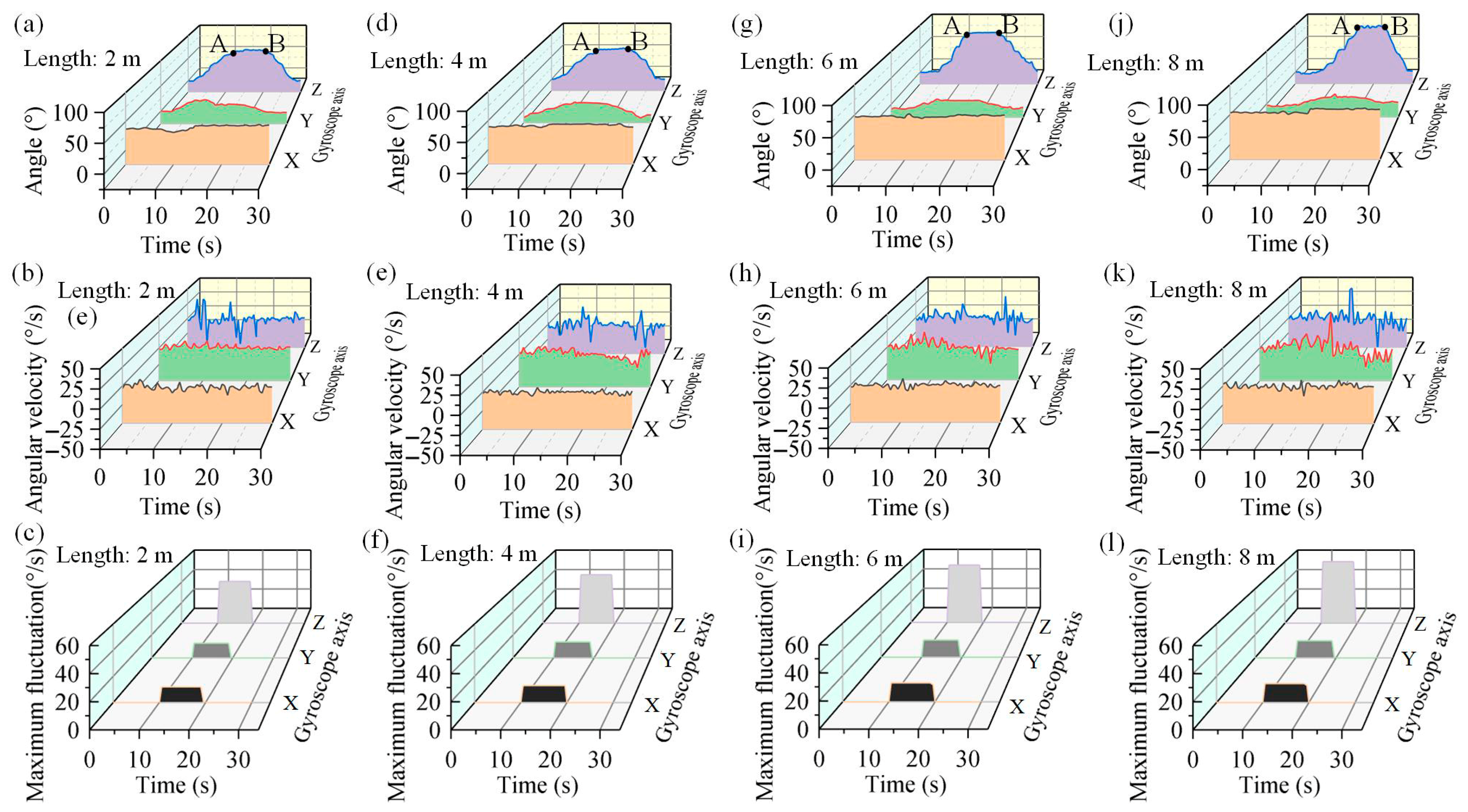
Continuum robots often work in unstructured environments and inevitably collide with objects in the environment. Thus, collision stability is the key to the safe operation of continuum robots. The motion characteristics of the UGCR are tested after colliding with obstacles during motion. Its rotation angles, angular velocities, and maximum fluctuations are shown in Figure 11, and the AB segment corresponds to the collision stage. It can be seen that after colliding with an obstacle, the UGCR adheres to the surface of the obstacle and forms a new stable state, such as the AB segments in Figure 11a,d,g,j. However, the fluctuation amplitude becomes slightly larger after the collision as the length of the UGCR continuum body increases (Figure 11c,f,i,l). When the UGCR moves in the opposite direction (after time instant B in Figure 11), it successfully detaches from the obstacle and continues to perform the expected task stably. The UGCR not only does not harm colliding objects but also forms a relatively stable state on its own. Therefore, the UGCR maintains motion reliability even in multi-obstacle environments.

4.3. Load Performance

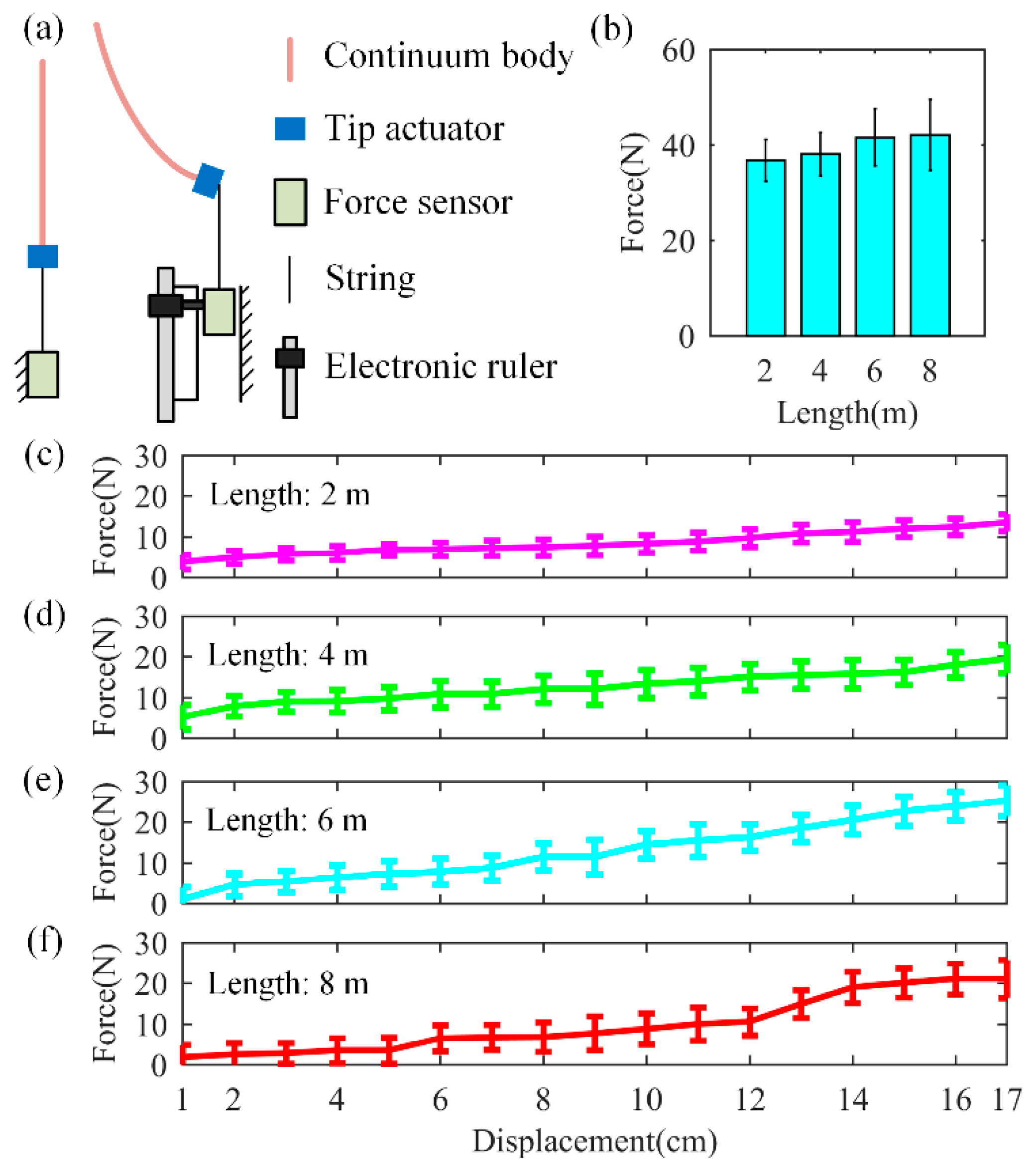
Load capacity is an important performance indicator for continuum robots. Due to the inherent low stiffness of ultra-long continuum robots, their load capacity is generally small. Load tests are conducted on the UGCR with different lengths to measure its load performance. First, the starting force of the UGCR is tested, and the schematic diagram of the measurement device is shown in the left subfigure of Figure 12a. The test results are shown in Figure 12b, where it can be seen that the starting force of the UGCR increases slightly as its continuum body becomes longer. When it reaches its maximum length of 8 m, its average starting force is equal to 42.1 N. After multiple tests, the rated load of the UGCR in the swinging state was measured to be 500 g.
Meanwhile, the relationship between the force and the displacement at the tip of the UGCR was also tested starting from its highest point. The schematic diagram of the measurement device is shown in the right figure of Figure 12a. The test results for the UGCR with lengths of 2 m, 4 m, 6 m, and 8 m are shown in Figure 12c–f. It can be seen that when the continuum body length of the UGCR is less than 6 m (Figure 12c–e), the relationship between the force and displacement at its tip is almost linear. However, when the continuum body length of the UGCR is larger, the relationship between the force and the displacement at its tip becomes nonlinear (Figure 12f). Note that the load capacity of the UGCR is relatively low, which is a common challenge faced by ultra-long continuum robots at present. Therefore, the UGCR is mainly used for long-distance transmission of various liquids, detection in deep places, operation of lightweight objects, as well as human–machine cooperation.

5. Discussion

Existing growing robots excel at constructing 3D structures along their movement path; however, they are unable to move continuously in real time. With a tip-driven mechanism, the growing continuum robot developed here achieves continuous real-time motion within the workspace by controlling the magnitude and direction of the tip actuation force. Moreover, it features a simpler structure that enables greater length with a smaller diameter, allowing it to traverse tighter spaces. Additionally, compared to pneumatically driven growing robots, which may fail when damaged in harsh environments, this design demonstrates stronger resistance to disturbances and an improved load capacity, making it capable of pulling heavy objects.
Portability is a prerequisite for deploying the robot in real field conditions. The total mass of the UGCR is 6.5 kg, which meets portability requirements. On the other hand, it possesses steering capability via tip actuation and steering. However, there are some limitations of the UGCR. On the one hand, the growth mechanism of the UGCR leads to growth only in the direction of gravity and is not suitable for operations on sloped surfaces. In the future, we plan to modify the tip-driven mechanism—for instance, by incorporating a wall-climbing robot as the tip actuator—to enhance its operational capability on slopes. On the other hand, the UGCR currently relies only on simple actuator control (motor + fan); its repetitive motion accuracy is insufficient and cannot adapt to complex environmental operations. The main purpose is to preliminarily verify the basic feasibility and workflow of the ultra-long continuum structure in target applications. This design allowed us to focus on the core mechanical characteristics and hardware integration challenges of the robot within a relatively straightforward control framework, thereby establishing a reliable and reproducible baseline platform for subsequent advanced control algorithms. Our future work will focus on integrating advanced control strategies with visual feedback in a closed-loop system to improve its motion accuracy. Given the complex kinematics and dynamics of our robot, MPC would indeed be a highly suitable approach. A dynamic model of the robot could be developed and incorporated into an MPC framework, enabling the system to predict future states and optimize control inputs (motor speeds, fan thrusts) to achieve desired trajectories while adhering to constraints such as maximum curvature and self-collision avoidance. Visual feedback from cameras would provide essential state estimation—such as tip position and overall shape—to close the control loop. This direction will be included as part of our future work.

6. Conclusions

This work has tackled the development challenge of ultra-long and minor-diameter continuum robots from the perspectives of lightweight design and new shape control mechanisms. We have developed an 8 m long continuum robot with a diameter of 23 mm by a tip actuation and growth mechanism. The untethered design of the continuum robot greatly improves its portability and mobility. We have established a static model to predict the deformation of the UGCR, and its prediction error is within 2.6% compared with the experimental results. The manipulation experiment shows that the UGCR has good flexibility and can perform obstacle crossing and target searching. Meanwhile, its continuum body enables the long-distance transportation of liquids, providing water, medicine, and other rescue items for trapped individuals. The functionality of the UGCR can be expanded by installing different tools. For example, by combining a hook with an outlet pipe at its tip, it can pick up objects and spray liquids in deep wells, pits, and other scenarios.
In addition, we have verified the workspace and motion performance of the UGCR through a combination of testing and analysis. The motion fluctuations of the UGCR generally increase with its length. The directional and displacement interference experiments show that the UGCR generates motion fluctuations under interference—but gradually forms a stable state after the interference disappears—and the difference from the state before the interference becomes larger with the increase in its length. The collision experiment shows that the UGCR adheres to the surface of obstacles and forms a new stable state after colliding with them, so that the fluctuation amplitude after collision is very small. Therefore, the UGCR can be operated in multi-object environments.

Supplementary Materials

The following supporting information can be downloaded at https://www.mdpi.com/article/10.3390/machines13090851/s1: Movie S1: motion demonstration of the untethered growing continuum robot. Movie S2: liquid delivery & target manipulation of the untethered growing continuum robot.

Author Contributions

Conceptualization, P.Z.; Methodology, P.Z.; Validation, P.Z. and Z.L.; Formal analysis, P.Z.; Investigation, Z.L. and L.Z.; Resources, H.L.; Data curation, P.Z., Z.L. and L.Z.; Writing—original draft, P.Z.; Writing—review & editing, J.Y.; Visualization, M.B.; Supervision, H.L., M.B. and J.Y.; Funding acquisition, H.L. All authors have read and agreed to the published version of the manuscript.

Funding

This research was supported, in part, by the National Natural Science Foundation of China (Grant No. 52505026), Natural Science Foundation of Zhejiang Province (under Grant LQ24E050001), Ningbo Technology Innovation 2035 Project (Grant No. 2024Z066), and Ningbo Technology Innovation 2035 Project (Grant No. 2024Z167).

Data Availability Statement

The original contributions presented in this study are included in the article/Supplementary Material. Further inquiries can be directed to the corresponding author(s).

Conflicts of Interest

The authors declare no conflicts of interest.

References

  1. Russo, M.; Sadati, S.M.H.; Dong, X.; Mohammad, A.; Walker, I.D.; Bergeles, C.; Xu, K.; Axinte, D.A. Continuum robots: An overview. Adv. Intell. Syst. 2023, 5, 2200367. [Google Scholar] [CrossRef]
  2. Chen, G.; Tang, S.; Duan, X.; Wang, H. Design, modeling, and evaluation of parallel continuum robots: A survey. Sci. China Technol. Sci. 2024, 67, 673–695. [Google Scholar] [CrossRef]
  3. Wu, H.; Yu, J.; Pan, J.; Pei, X. A novel obstacle avoidance heuristic algorithm of continuum robot based on FABRIK. Sci. China Technol. Sci. 2022, 65, 2952–2966. [Google Scholar] [CrossRef]
  4. Yang, Z.; Yang, H.; Cao, Y.; Cui, Y.; Zhang, L. Magnetically actuated continuum medical robots: A review. Adv. Intell. Syst. 2023, 5, 202200416. [Google Scholar] [CrossRef]
  5. Chen, X.; Zhang, X.; Huang, Y.; Cao, L.; Liu, J. A review of soft manipulator research, applications, and opportunities. J. Field Robot. 2022, 39, 281–311. [Google Scholar] [CrossRef]
  6. Fang, Y.; Dong, X.; Mohammad, A.; Axinte, D. Design and control of a multiple-section continuum robot with a hybird sensing system. IEEE/ASME Trans. Mechatron. 2023, 28, 1522–1533. [Google Scholar] [CrossRef]
  7. Leibrandt, K.; da Cruz, L.; Bergeles, C. Designing robots for reachability and dexterity: Continuum surgical robots as a pretext application. IEEE Trans. Robot. 2023, 39, 2989–3007. [Google Scholar] [CrossRef]
  8. Nwafor, C.; Laurent, G.J.; Rabenorosoa, K. Miniature parallel continuum robot made of glass: Analysis, design, and proof-of-concept. IEEE/ASME Trans. Mechatron. 2023, 28, 2038–2046. [Google Scholar] [CrossRef]
  9. Zhang, T.; Yang, L.; Yang, X.; Tan, R.; Lu, H.; Shen, Y. Millimeter-scale soft continuum robots for large-angle and high-precision manipulation by hybrid actuation. Adv. Intell. Syst. 2021, 3, 202000189. [Google Scholar] [CrossRef] [PubMed]
  10. Hyatt, P.; Kraus, D.; Sherrod, V.; Rupert, L.; Day, N.; Killpack, M.D. Configuration estimation for accurate position control of large-scale soft robots. IEEE/ASME Trans. Mechatron. 2019, 24, 88–99. [Google Scholar] [CrossRef]
  11. Li, X.; Sun, K.; Guo, C.; Liu, H. Modeling and experimental validation for a large-scale and ultralight inflatable robotic arm. IEEE/ASME Trans. Mechatron. 2022, 27, 418–429. [Google Scholar] [CrossRef]
  12. Li, X.; Sun, K.; Guo, C.; Liu, H. Hybrid adaptive disturbance rejection control for inflatable robotic arms. ISA Trans. 2022, 126, 617–628. [Google Scholar] [CrossRef] [PubMed]
  13. Yang, H.D.; Asbeck, A.T. Design and characterization of a modular hybrid continuum robotic manipulator. IEEE/ASME Trans. Mechatron. 2020, 25, 2812–2823. [Google Scholar] [CrossRef]
  14. Zhang, Z.; Tang, S.; Fan, W.; Xun, Y.; Wang, H.; Chen, G. Design and analysis of hybrid-driven origami continuum robots with extensible and stiffness-tunable sections. Mech. Mach. Theory 2022, 169, 104607. [Google Scholar] [CrossRef]
  15. Lee, K.; Wang, Y.; Zheng, C. TWISTER hand: Underactuated robotic gripper inspired by origami twisted tower. IEEE Trans. Robot. 2020, 36, 488–500. [Google Scholar] [CrossRef]
  16. Santoso, J.; Onal, C.D. An origami continuum robot capable of precise motion through torsionally stiff body and smooth inverse kinematics. Soft Robot. 2021, 8, 371–386. [Google Scholar] [CrossRef] [PubMed]
  17. Jiang, H.; Wang, Z.; Jin, Y.; Chen, X.; Li, P.; Gan, Y.; Lin, S.; Chen, X. Hierarchical control of soft manipulators towards unstructured interactions. Int. J. Robot. Res. 2021, 40, 411–434. [Google Scholar] [CrossRef]
  18. Melancon, D.; Forte, A.E.; Kamp, L.M.; Gorissen, B.; Bertoldi, K. Inflatable origami: Multimodal deformation via multistability. Adv. Funct. Mater. 2022, 32, 202201891. [Google Scholar] [CrossRef]
  19. Kim, W.; Byun, J.; Kim, J.-K.; Choi, W.-Y.; Jakobsen, K.; Jakobsen, J.; Lee, D.-Y.; Cho, K.-J. Bioinspired dual-morphing stretchable origami. Sci. Robot. 2019, 4, eaay3493. [Google Scholar] [CrossRef]
  20. Oh, N.; Rodrigue, H. Toward the development of large-scale inflatable robotic arms using hot air welding. Soft Robot. 2023, 10, 88–96. [Google Scholar] [CrossRef] [PubMed]
  21. Alvarez-Palacio, J.M.; Monteiro, E.; Riwan, A.; Mechbal, N. A novel inflatable actuator based on simultaneous eversion retraction. Soft Robot. 2021, 8, 699–710. [Google Scholar] [CrossRef]
  22. Goswami, D.; Liu, S.; Pal, A.; Silva, L.G.; Martinez, R.V. 3D-architected soft machines with topologically encoded motion. Adv. Funct. Mater. 2019, 29, 201808713. [Google Scholar] [CrossRef]
  23. Rubio, A.P.; Fan, D.; Jenett, B.; Ferrandis, J.d.Á.; Tourlomousis, F.; Abdel-Rahman, A.; Preiss, D.; Zemánek, J.; Triantafyllou, M.; Gershenfeld, N. Modular morphing lattices for large-scale underwater continuum robotic structures. Soft Robot. 2023, 10, 724–736. [Google Scholar] [CrossRef] [PubMed]
  24. Zhang, J.; Hu, Y.; Li, Y.; Ma, K.; Wei, Y.; Yang, J.; Wu, Z.; Rajabi, H.; Peng, H.; Wu, J. Versatile like a seahorse tail: A bio-inspired programmable continuum robot for conformal grasping. Adv. Intell. Syst. 2022, 4, 202200263. [Google Scholar] [CrossRef]
  25. Maloisel, G.; Knoop, E.; Schumacher, C.; Bacher, M. Automated routing of muscle fibers for soft robots. IEEE Trans. Robot. 2021, 37, 996–1008. [Google Scholar] [CrossRef]
  26. Xing, Z.; Zhang, J.; McCoul, D.; Cui, Y.; Sun, L.; Zhao, J. A super-lightweight and soft manipulator driven by dielectric elastomers. Soft Robot. 2020, 7, 512–520. [Google Scholar] [CrossRef]
  27. Atia, M.G.B.; Mohammad, A.; Gameros, A.; Axinte, D.; Wright, I. Reconfigurable soft robots by building blocks. Adv. Sci. 2022, 9, e2203217. [Google Scholar] [CrossRef]
  28. Kim, Y.; Parada, G.A.; Liu, S.; Zhao, X. Ferromagnetic soft continuum robots. Sci. Robot. 2019, 4, eaax7329. [Google Scholar] [CrossRef]
  29. Lin, D.; Jiao, N.; Wang, Z.; Liu, L. A magnetic continuum robot with multi-mode control using opposite-magnetized magnets. IEEE Robot. Autom. Lett. 2021, 6, 2485–2492. [Google Scholar] [CrossRef]
  30. Blumenschein, L.H.; Coad, M.M.; Haggerty, D.A.; Okamura, A.M.; Hawkes, E.W. Design, modeling, control, and application of everting vine robots. Front. Robot. AI 2020, 7, 548266. [Google Scholar] [CrossRef]
  31. Talas, S.K.; Baydere, B.A.; Altinsoy, T.; Tutcu, C.; Samur, E. Design and development of a growing pneumatic soft robot. Soft Robot. 2020, 7, 521–533. [Google Scholar] [CrossRef] [PubMed]
  32. Coad, M.M.; Thomasson, R.P.; Blumenschein, L.H.; Usevitch, N.S.; Hawkes, E.W.; Okamura, A.M. Retraction of soft growing robots without buckling. IEEE Robot. Autom. Lett. 2020, 5, 2115–2122. [Google Scholar] [CrossRef]
  33. Blumenschein, L.H.; Koehler, M.; Usevitch, N.S.; Hawkes, E.W.; Rucker, D.C.; Okamura, A.M. Geometric solutions for general actuator routing on inflated-beam soft growing robots. IEEE Trans. Robot. 2022, 38, 1820–1840. [Google Scholar] [CrossRef]
  34. Greer, J.D.; Morimoto, T.K.; Okamura, A.M.; Hawkes, E.W. A soft, steerable continuum robot that grows via tip Extension. Soft Robot. 2019, 6, 95–108. [Google Scholar] [CrossRef]
  35. Satake, Y.; Takanishi, A.; Ishii, H. Novel growing robot with inflatable structure and heat-welding rotation mechanism. IEEE/ASME Trans. Mechatron. 2020, 25, 1869–1877. [Google Scholar] [CrossRef]
  36. Satake, Y.; Ishii, H. Pitch-up motion mechanism with heat welding by soft inflatable growing robot. IEEE Robot. Autom. Lett. 2022, 7, 5071–5078. [Google Scholar] [CrossRef]
  37. Li, P.; Zhang, Y.; Zhang, G.; Zhou, D.; Li, L. A bioinspired soft robot combining the growth adaptability of vine plants with a coordinated control system. Research 2021, 2021, 9843859. [Google Scholar] [CrossRef]
  38. Coad, M.M.; Blumenschein, L.H.; Cutler, S.; Zepeda, J.A.R.; Naclerio, N.D.; El-Hussieny, H.; Mehmood, U.; Ryu, J.-H.; Hawkes, E.W.; Okamura, A.M. Vine robots: Design, teleoperation, and deployment for navigation and exploration. IEEE Robot. Autom. Mag. 2019, 27, 120–132. [Google Scholar] [CrossRef]
  39. Hawkes, E.W.; Blumenschein, L.H.; Greer, J.D.; Okamura, A.M. A soft robot that navigates its environment through growth. Sci. Robot. 2017, 2, eaan3028. [Google Scholar] [CrossRef] [PubMed]
  40. Yamaguchi, T.; Ambe, Y.; Ando, H.; Konyo, M.; Tadakuma, K.; Maruyama, S.; Tadokoro, S. A mechanical approach to suppress the oscillation of a long continuum robot flying with water jets. IEEE Robot. Autom. Lett. 2019, 4, 4346–4353. [Google Scholar] [CrossRef]
  41. Li, S.; Awale, S.A.; Bacher, K.E.; Buchner, T.J.; Della Santina, C.; Wood, R.J.; Rus, D. Scaling up soft robotics: A meter-scale, modular, and reconfigurable soft robotic system. Soft Robot. 2022, 9, 324–336. [Google Scholar] [CrossRef] [PubMed]
Figure 1. The motion principle of an untethered growing continuum robot. (a) The principle of length and shape control. (b) The principle of direction control. (c) The motion diagram of the continuum robot.
Machines 13 00851 g001
Figure 2. Prototype of the untethered growing continuum robot.
Machines 13 00851 g002
Figure 3. Spatial pose description (a) and force diagram (b) of the continuum body.
Machines 13 00851 g003
Figure 4. Comparison between theoretical and experimental results of maximum deformation of UGCR with lengths of 2 m (a), 4 m (b), 6 m (c), and 8 m (d), respectively.
Machines 13 00851 g004
Figure 5. Demonstration experiments of the untethered growing continuum robot. Front view (a) and top view (b) of its different motion positions. (c) The motion states of the UGCR when its length is equal to 4.5 m or 8 m, respectively. (d) The UGCR moves along the pillar. (e) The UGCR moves along the edge of the step. (f) The UGCR enables motion navigation and target search by a camera. (g) Obstacle crossing experiment. (h) Human–machine interaction experiment. Continuum bodies in certain different motion states are highlighted with color lines.
Machines 13 00851 g005
Figure 6. Manipulation experiments of the untethered growing continuum robot. (a) Schematic diagram of the liquid conveying setup. (b) The UGCR can utilize its continuum body to deliver liquid to a target. (c) The experiment of searching and picking up a target.
Machines 13 00851 g006
Figure 7. The workspace of the untethered growing continuum robot. Axonometric view (a), X-Z view (b), and X-Y view (c) of the workspace. (d) The shape of the continuum body under different lengths at the edge of the workspace.
Machines 13 00851 g007
Figure 8. The tip rotation angle and angular velocity of the UGCR during motion. (a,d,g,j) are the rotation angles of the UGCR with lengths of 2 m, 4 m, 6 m, and 8 m, respectively. (b,e,h,k) are the angular velocities of the UGCR with lengths of 2 m, 4 m, 6 m, and 8 m, respectively. (c,f,i,l) are the maximum angular velocity fluctuations of the UGCR with lengths of 2 m, 4 m, 6 m, and 8 m, respectively.
Machines 13 00851 g008
Figure 9. The rotation angles and angular velocities of the UGCR under interference from direction. (a,d,g,j) are the rotation angles for the UGCR with lengths of 2 m, 4 m, 6 m, and 8 m, respectively, when it is subjected to a directional interference at a frequency of 2 Hz. (b,e,h,k) are the angular velocities for the UGCR with lengths of 2 m, 4 m, 6 m, and 8 m, respectively, when it is subjected to a directional interference at a frequency of 2 Hz. (c,f,i,l) are the angle fluctuations of the UGCR with lengths of 2 m, 4 m, 6 m, and 8 m, respectively, when it is subjected to a directional interference at a frequency of 2 Hz.
Machines 13 00851 g009
Figure 10. The rotation angles and angular velocities of the UGCR under interference from displacement. (a,d,g,j) are the rotation angles for the UGCR with a load of 8 N with lengths of 2 m, 4 m, 6 m, and 8 m, respectively, when it is subjected to a displacement interference of 10 cm in the direction of gravity with a load of 8 N at a frequency of 2 Hz. (b,e,h,k) are the angular velocities for the UGCR with lengths of 2 m, 4 m, 6 m, and 8 m, respectively, when it is subjected to a displacement interference of 10 cm in the direction of gravity with a load of 8 N at a frequency of 2 Hz. (c,f,i,l) are the angle fluctuations of the UGCR with lengths of 2 m, 4 m, 6 m, and 8 m, respectively, when it is subjected to a displacement interference of 10 cm in the direction of gravity with a load of 8 N at a frequency of 2 Hz.
Machines 13 00851 g010
Figure 11. The rotation angles and angular velocities of the UGCR when colliding with obstacles during motion. (a,d,g,j) are the rotation angles of the moving UGCR with lengths of 2 m, 4 m, 6 m, and 8 m, respectively, when colliding with an obstacle. (b,e,h,k) are the angular velocities of the moving UGCR with lengths of 2 m, 4 m, 6 m, and 8 m, respectively, when colliding with an obstacle. (c,f,i,l) are the maximum angular velocity fluctuations of the moving UGCR with lengths of 2 m, 4 m, 6 m, and 8 m, respectively, when colliding with an obstacle during the AB phase.
Machines 13 00851 g011
Figure 12. The load performance of the UGCR. (a) Schematic diagram of the measurement device for the initial starting force of the UGCR (Left). Schematic diagram of the measurement device for the relationships between the force and the displacement of the UGCR from its highest point (Right). (b) The initial starting force of the UGCR with different lengths. (cf) are the relationships between the applied force and the displacement at the tip of the UGCR with different lengths starting from its highest point.
Machines 13 00851 g012
Disclaimer/Publisher’s Note: The statements, opinions and data contained in all publications are solely those of the individual author(s) and contributor(s) and not of MDPI and/or the editor(s). MDPI and/or the editor(s) disclaim responsibility for any injury to people or property resulting from any ideas, methods, instructions or products referred to in the content.