Abstract
This paper investigates the influence of the internal concave surface structure of the stirring tool and welding parameters on the microstructure and mechanical properties of the T-joint. The analysis reveals that compared to the inner concave surface without spirals, T-joints welded by inner concave surfaces with spirals exhibit fewer welding defects. Meanwhile, the microscopic results showed that there is a welding juncture zone between the thermomechanical affected zone and the nugget zone, and a large number of θ’, T1, and η’ phases precipitate in the nugget zone of the joint, which improves its strength and hardness. When welding speed v, rotational speed w and insertion depth h are 60 mm/min, 350 rpm, and 0.21 mm, respectively, the yield strength, the tensile strength, and the elongation of the T-joint reach their maximum values (352 MPa, 408 MPa and 5%), and the tensile strength represents 68.0% and 71.6% of the base materials, respectively. The fracture mechanism of the joint is a mode of ductile fracture. Furthermore, the T-joint exhibits a “W” and “Z” distribution pattern on both sides of the weld centerline B and A, respectively.
1. Introduction
Al-Li alloys have garnered significant attention in the aerospace industry due to their higher specific strength and stiffness, better corrosion resistance, fatigue resistance, and ductility [1,2]. Integral panels represent the most typical structural form in large commercial aircraft fuselages, and the widespread adoption of large integral panel structures has become an important means for the next generation of large commercial aircraft to improve structural efficiency, reduce the number of fasteners, lower costs, and shorten development cycles [3]. There are numerous T-joints on large integral panels, such as those found in fuselage, wing ribs, and cabin walls. However, T-joints often encounter issues such as porosity, cracking, deformation, and poor fatigue performance when welded using fusion welding techniques like laser or arc welding [4]. In comparison, friction stir welding (FSW), as an emerging solid-state joining technology [5], holds great promise for welding structural components such as fuselage skins, center wing boxes, and wing load-bearing walls. The heat in FSW originates from three sources: frictional heating between the shoulder end face of the stirring tool and the workpiece surface; frictional heating between the cylindrical surface of the welding pin and the interior of the workpiece; and frictional heating between the bottom surface of the welding pin and the workpiece [6]. According to reports [7,8,9,10,11,12,13,14,15,16,17,18,19,20,21,22,23], both the stirring tool and welding process parameters (v, w and h) have crucial effects on the FSW process of metallic materials.
The stirring tool has significant effects on heat generation, material flow, and joint life, with main geometric features including shoulder diameter, shoulder geometry, welding pin size and geometry [7,8]. Kaushik et al. [9] studied the influence of different shoulder diameters on Al/steel dissimilar material joints and found that a shoulder diameter of 13 mm, coupled with a cylindrical welding pin, generated the least heat and resulted in the strongest weld seam formation. Goel et al. [10] investigated the effects of different welding pin shapes on the microhardness, impact properties, and tensile properties of 6063-T6 alloy joints, discussing the formation of various defects during the FSW process through fracture surface analysis. Burek et al. [11] studied the impact of tool wear on the quality of 7075-T6 Al alloy lap joints, revealing a relationship between tool wear and the reduction in the size of the thermoplastic zone. Regensburg et al. [12] conducted FSW experiments on 1050/CW024A lap joints using welding pins of different lengths, finding that a welding pin length of 2.2 mm resulted in the highest failure load. Li et al. [13] conducted FSW experiments on 6061-T4 aluminum alloy T-joints using a self-developed stationary shoulder welding tool, finding that both the skin and stiffener hardness decreased compared to the base material, and all fractures occurred in the heat-affected zone.
Welding speed v is one of the key parameters affecting the quality of FSW. The welding line energy E is closely related to the rotational speed w, friction coefficient μ, welding speed ν, welding pin radius R0, shoulder radius R1, and stirring tool downward pressure F [14]. For example, when the dimensions of the stirring tool and w are constant, the heat generated by friction stir welding remains constant, but as ν increases, E decreases, resulting in insufficient plasticization of the alloy material, leading to surface irregularities, burrs, or even cracks on the joint surface, as well as internal defects such as voids or channel holes. Rotational speed w is another important welding parameter for FSW. Frigaard et al. [15] revealed that the heat input q into the welding joint is related to w; when q increases with w, metal material flows sufficiently, and the weld seam is easily formed. However, when q is too high, the alloy material is excessively plasticized, leading to a significant decrease in plasticized alloy viscosity. Conversely, when q is too low, there is insufficient frictional heat, and the alloy material is not sufficiently stirred, leading to the formation of grooves, channel holes, or even the fracture of the welding pin. Insertion depth h also directly affects the forming quality of the welding joint. Decreasing h leads to lower heat input during welding, which is unfavorable for the formation of high-quality weld seams, while increasing h exacerbates the degree of depression of the weld seam, causing stress concentration in the weld seam region and reducing the mechanical properties of the joints [16]. For dissimilar alloy butt joints, Gao et al. [17] analyzed the effect of rotational speed on the mechanical properties of the joints and found no significant defects inside the joints at a rotational speed of 1000 rpm. The tensile strength and elongation at breakness of 2195-T6 Al-Li alloy butt joints reach their maximum values when the welding speed is 180 mm/min [18]. Furthermore, an appropriate combination of process parameters can simultaneously satisfy the optimization for the ultimate strength, impact toughness, hardness, and other comprehensive properties of the joints [19]. Liu et al. [20] demonstrated that under the parameter combination of a rotational speed of 400 rpm and a welding speed of 100 mm/min, the surface forming quality of the weld seam at the joint is better, with tensile strength (360 MPa) reaching 83.9% of the base material. For T-joints, Yang et al. [21] investigated the macroscopic forming and mechanical properties of Al alloy T-joint welds affected by stirring tool rotational speed n, while Thomae, Su et al. [22,23] studied the impact of rotation and welding speed on the impact properties of titanium alloy T-joints. Raj et al. [24] studied SS316L/Inconel 718 butt joints using induction-assisted FSW and found that w was 300 rpm, v was 140 mm/min and preheating was 30 °C, the joints were defect-free. It can be seen that current FSW research mainly focuses on dissimilar, same materials butt joints, lap joints or T-joints of the same materials, but reports on dissimilar material FSW-T joints are very rare [25], especially in the welding of third-generation new alloys such as Al 7055-T6 and Al-Li 2197-T8.
Therefore, this study employs FSW technology to conduct T-joint welding experiments on two types of alloy materials, Al 7055-T61 and Al-Li 2197-T8, to investigate the effects of stirring tool geometry and welding process parameters on the morphology and properties of T-joint welds, providing reference and practical significance for the high-quality connection of FSW-T joints in large aircraft integral panels in the future.
2. Experimental Procedure
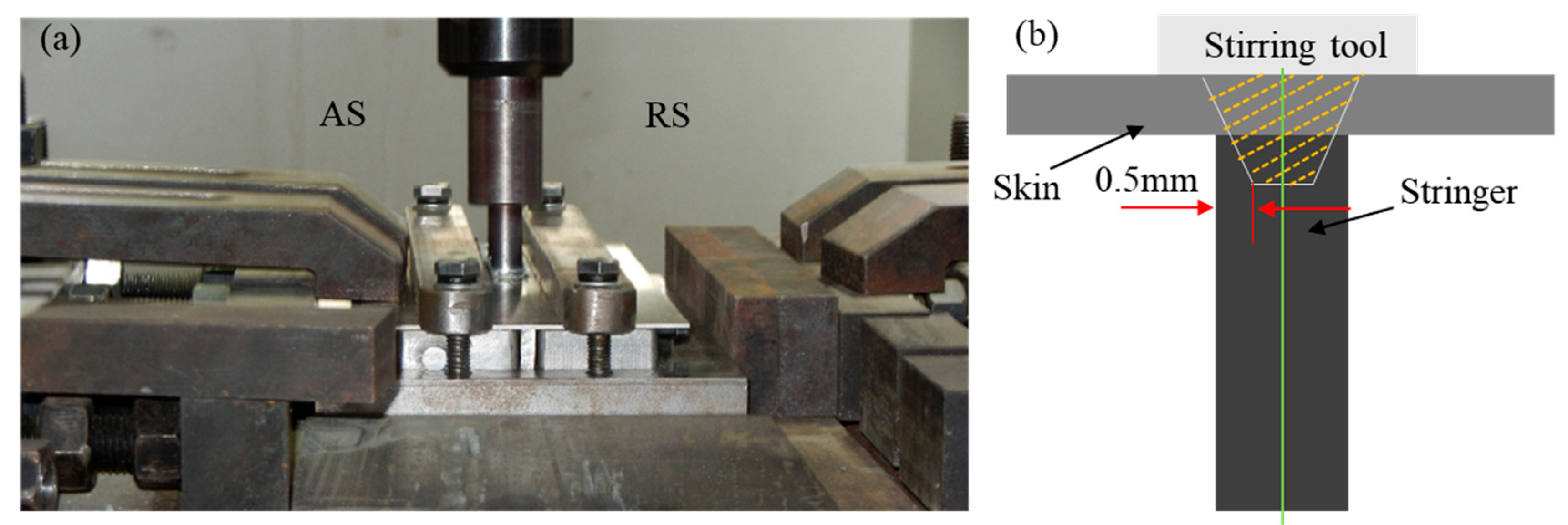
The 7055-T61 alloy with 1.6% to 3.3% pre-stretch treatment has better mechanical properties [26]. In this experiment, the dimension of 7055-T61 Al alloy, as the skin, is 200 × 80 × 1.5 mm, and that of 2197-T8 Al-Li alloy, as the stringer, is 200 × 5 × 13 mm. The large integral panel is composed of the abdominal plate and stiffener. The T-shaped stiffened panel welded by FSW technology (see Figure 1a) is equivalent to a single T-shaped stiffened panel cut in the X direction along the above-mentioned large integral panel [27]. The side of the stirring tool whose rotation direction is the same as the welding speed is defined Advanced Side (abbreviated AS), and the opposite is defined Retreating Side (Abbreviated RS). Figure 1 shows the welding process and method of T-shaped stiffened panels. The chemical composition and room-temperature properties of the materials used in the experiment are shown in Table 1 and Table 2.
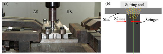
Figure 1.
Views of FSW and the corresponding method at (a) T-welding process and (b) lap joining with T-joints.

Table 1.
Chemical composition of Al 7055-T61 and Al-Li 2197-T8 alloys (mass fraction, %).

Table 2.
Room temperature properties of 7055-T61 and 2197-T8 alloys [26].
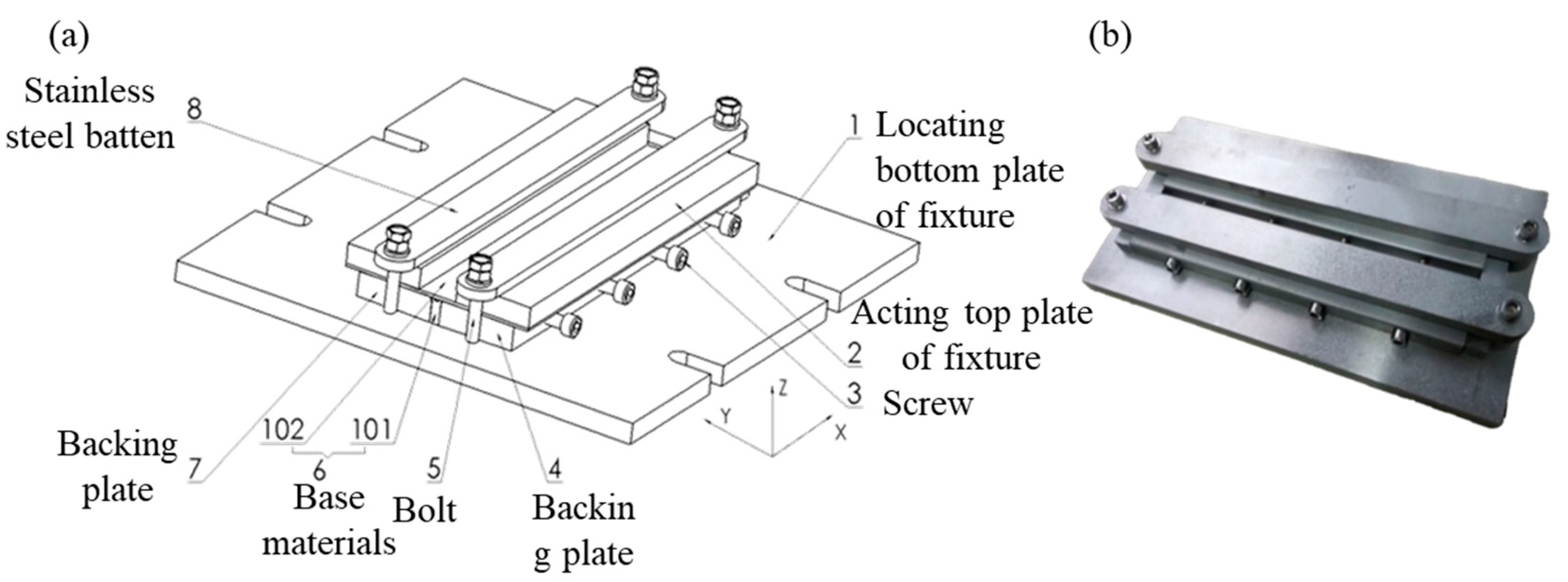
FSW is very demanding on welding fixtures [28]. In the process of FSW, it is not only required that the fixture has high stiffness and heat resistance, and the welded part has extremely high holding forces, but also when the T-joint is welding, the thin plate and the stringer need to be aligned and fixed firmly to prevent deviation in the welding. Therefore, Figure 2a is a schematic diagram of a specialized fixture designed specifically for this FSW experiment, and the corresponding physical drawing is shown in Figure 2b.
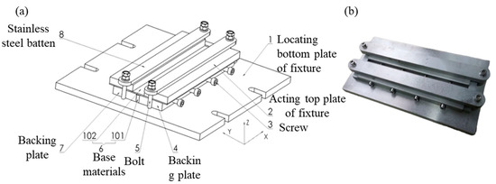
Figure 2.
Designed FSW special fixture with (a) schematic diagram and the corresponding (b) physical object.
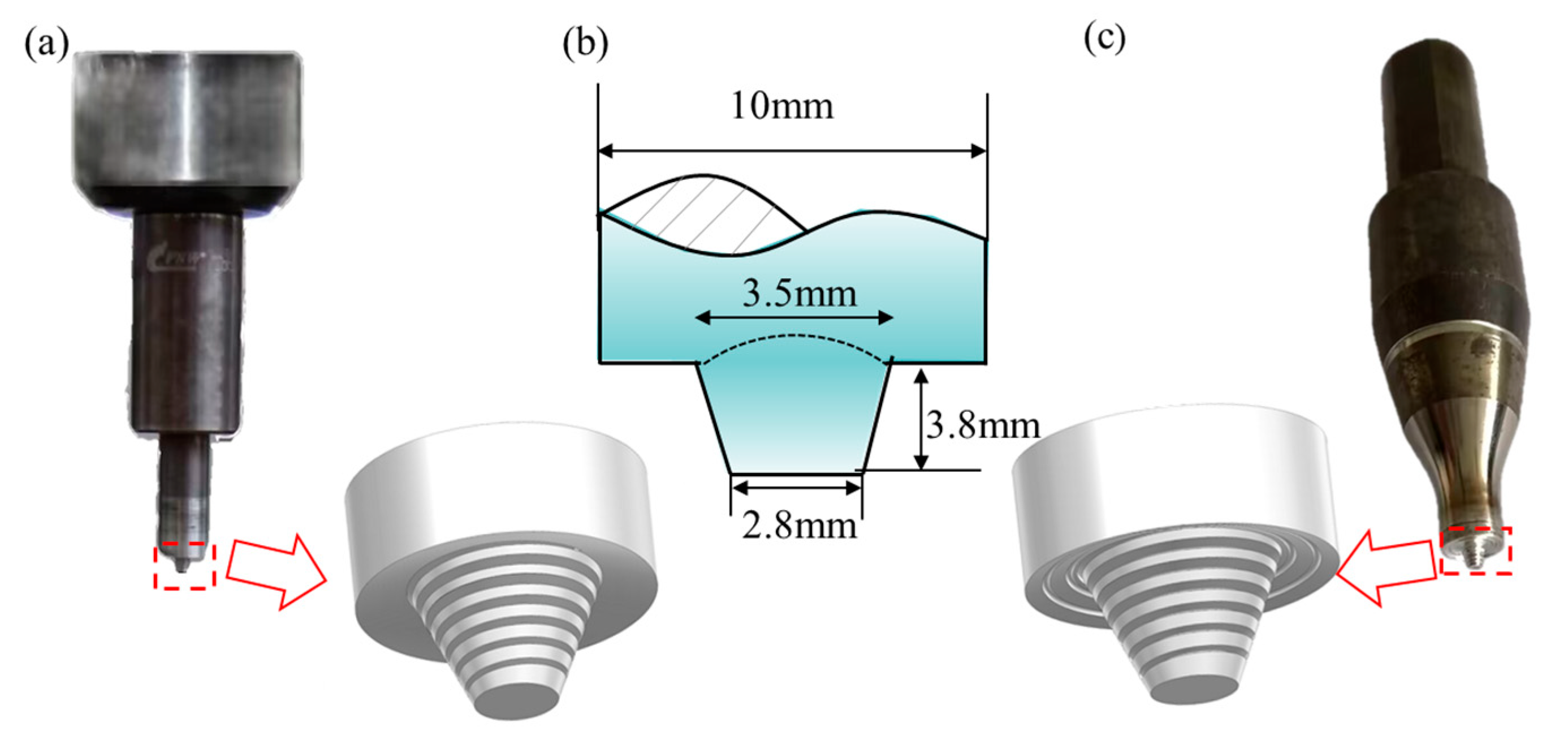
Welding speed (v), rotational speed (w), insertion depth (h) and stirring tool structure have an important influence on the forming and mechanical properties of T-joints [29,30,31]. The welding pins were designed as conical thread structures, but the difference was that the stirring tool shoulder structures. The first shoulder was the inner concave surface without spirals, abbreviated as ICSWOS (see Figure 3a), and the second shoulder was the inner concave surface with spirals, abbreviated as ICSWS (see Figure 3c). The diameters of the shoulders were 10 mm and the lengths of the stirring pins were 3.8 mm. The diameters of the small and large ends of the stirring pin were 2.8 mm and 3.5 mm, respectively [8]. Figure 3b presents the structure diagram of the stirring tools.
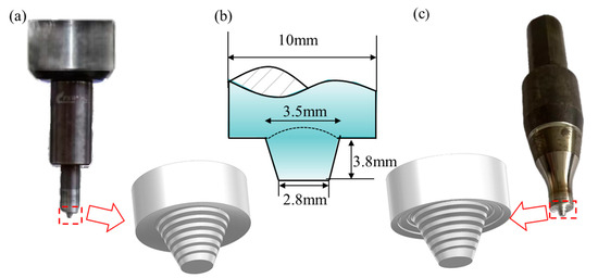
Figure 3.
Physical and contour images for the mixing tool structure with (a) ICSWOS, (b) structural dimensions, and (c) ICSWS.
The controlled variable method was used to investigate the effects of welding parameters and stirring tool structures on the morphology of T-joints. During the welding process, the tool tilt angle is set to 2.5°, and the downward pressure and rotational speed are 25 KN and 30 mm/min, respectively. When h = 0.21 mm, v, w, and the stirrer tool structure are set as variables. Table 3 depicts the welding process parameters corresponding to different shoulder structures.

Table 3.
Combination of welding parameters for different v, w, h and shoulder structures.
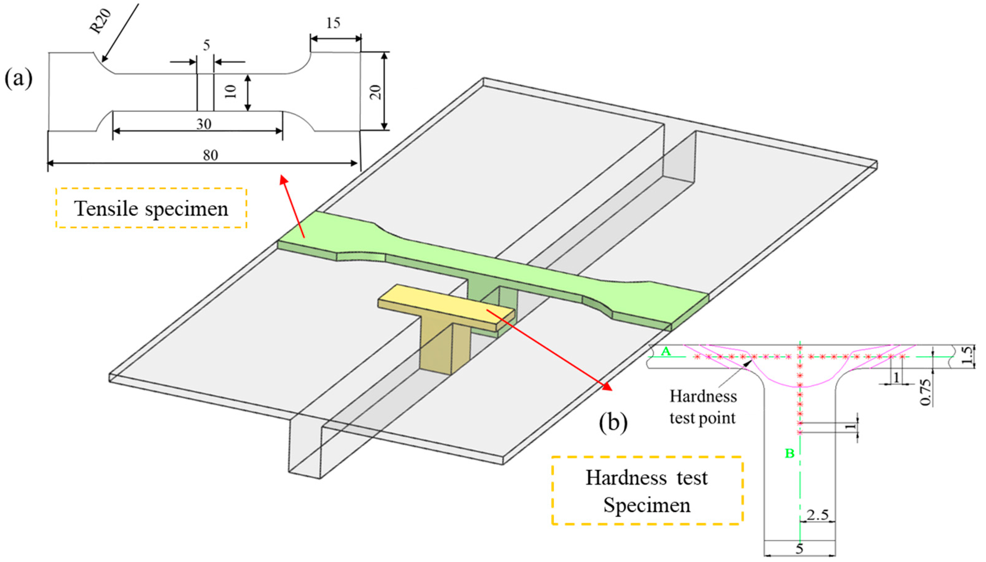
After welding, the optical samples were sectioned. All samples were ground with abrasive paper, polished, and etched with Keller’s reagent before being subjected to OM (RX50M, Sunny Group, Yuyao City, Zhejiang Province, China) analysis and TEM (JEM-2000CX, Tokyo, Japan) analysis of intragranular and grain boundary characteristics in the weld nugget zone (NZ). Besides a having good surface and internal appearance, the mechanical comprehensive performance of the joint is also good. Tensile specimens were sectioned perpendicular to the welding direction as shown in Figure 4a. Specimen preparation strictly followed the Standard Test Method for Tensile Testing of Welded Joints [32], with dimensions detailed in Figure 4a. The tensile loading direction was aligned with the specimen axis at a constant crosshead speed of 1 mm/min. After the specimens were pulled to fracture, the peak force and peak strain were recorded. Further observation of the tensile fracture morphology was carried out by SEM (KYKY SEM3200, Wuxi Chuanghui Measurement Technology Co., LTD, Wuxi, China), with each set of welding parameters tested three times. The hardness test was carried out on the HVS-1000 series digital micro-Vickers hardness tester (Jitai Technology, Beijing, China) with a test load of 200 gf and a loading time of 10 s. Figure 4b illustrates the microhardness test positions. Hardness values were continuously tested along the centerline A in the direction of the thin plate thickness of the joints and along the centerline B in the direction of the stringer thickness, with a spacing of 1 mm between each test point.
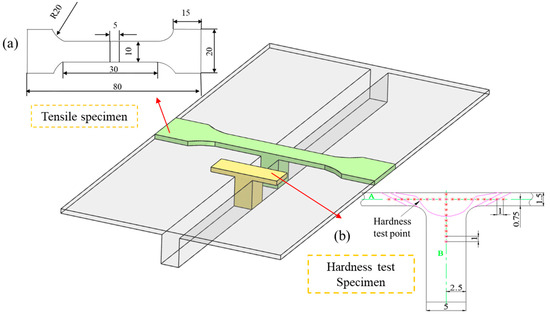
Figure 4.
Geometric of tensile specimen for the T-shaped stiffened plate, views of loading for the test machine with (a) dimensional profile and (b) hardness test position.
3. Results and Discussion
3.1. Forming Characteristics of T-Joint Welds
3.1.1. Weld Surface Morphology
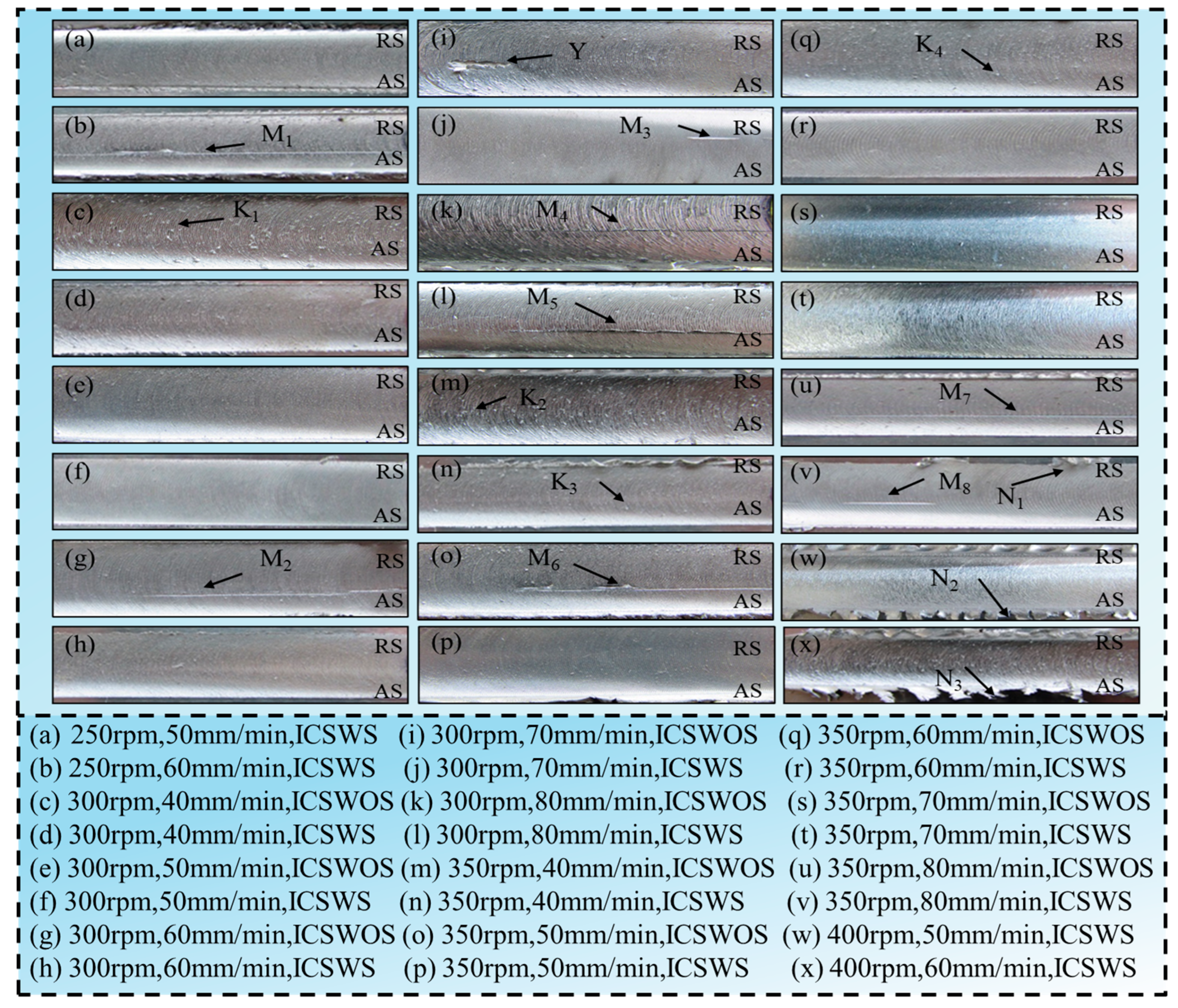
Different process parameters have a significant impact on the surface morphology of T-joints, and inappropriate heat input can lead to deteriorated joint performance. When the heat input is too low, the plasticization of materials is insufficient, and it cannot flow adequately. When the heat input is too high, the material is excessively plasticized, resulting in the formation of a large number of flashes on the weld seam surface [33]. Figure 5a–x, respectively, show the surface morphology of joint welds obtained under conditions of w = 250 rpm, w = 300 rpm, w = 350 rpm, and w = 400 rpm, with their defect types listed in Table 4. For convenience of description, K, M, Y, and N represent roughness, groove, channel, and flash defects, respectively, with subscripts indicating inconsistencies in the severity of joint weld defects. From Figure 5, it can be observed that the surface morphology of welds in Figure 5d,f,h,j,l,n,p,r,t is significantly better than the corresponding Figure 5c,e,g,i,k,m,o,q,s, respectively. This phenomenon demonstrates that welds produced using the ICSWS structure exhibit fewer defects than those created with the ICSWOS structure. This improvement stems from the shoulder’ s enhanced heat generation, which arises from dual thermal mechanisms: frictional heating and plastic deformation heat. According to the frictional heat formula:
where μ is the friction coefficient, p is the normal pressure on the contact surface, and v is the relative velocity between the tool and workpiece. During FSW, the spiral feature reduces the actual contact area. Under identical axial downward force, this increases the normal pressure p on the contact surface, thereby significantly enhancing frictional heat generation. Simultaneously, the spiral influences the local relative velocity v, further modulating heat production. The spiral configuration intensely stirs and shears the metal, promoting plastic deformation and material flow. This increases the volume of metal undergoing deformation and friction in the contact zone, generating additional heat. The plastic deformation heat is governed by
where η is the energy conversion efficiency (ratio of strain energy converted to heat), σ is the applied stress, ε̇ is the strain rate and V is the volume of plastically deformed material. Stress concentration occurs at spiral locations, elevating σ while localizing ε̇. When multiplied by the corresponding volume V, this substantially increases plastic deformation heat. Consequently, the ICSWS shoulder structure concentrates heat distribution more effectively, enabling a uniform temperature field in the weld zone. This facilitates thorough material mixing and directs material flow along the rotational direction to fill the cavity behind the welding pin.
q = μpv
Qdeformatio = η σ ε̇ V
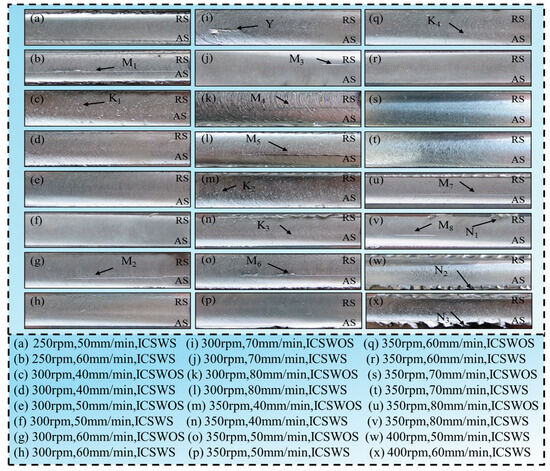
Figure 5.
Local weld surface morphology of T-joints with different v, w and h = 0.21 mm.

Table 4.
Possible defect types of welds under different parameters.
When the w is 250 rpm, and the insertion depth h and v are 0.21 mm and 60 mm/min, respectively, joints welded using the ICSWS structure exhibit poor surface formation, characterized by groove M1, as shown in Figure 5b. This occurs because the excessively low w results in insufficient heat input and relatively inadequate frictional heat generation, leading to poorer flow characteristics and higher viscosity of the plasticized material. When using the ICSWS shoulder structure with parameter combinations of [300 rpm, 40~60 mm/min, 0.21 mm] and [350 rpm, 40~70 mm/min, 0.21 mm], the weld surface quality is good. However, when v increases to 70 or 80 mm/min, the joint surface formation deteriorates, showing grooves M3, M5, M8, and flash N1, as seen in Figure 5j,l,v, respectively. The occurrence of these phenomena is attributed to the constant w, where excessively high v reduces the welding line energy, resulting in uneven and insufficient stirring of the weld zone. When w is increased to 400 rpm, h is 0.21 mm, v is 50 or 60 mm/min, and tool structure is ICSWS exhibit numerous flashes N2 and N3 on the surface (see Figure 5w,x). This is because the excessively large w dramatically increases the heat input, causing the alloy material to be fully plasticized, carried from the AS to the RS, and ultimately overflow occurs, forming flashes [15].
In summary, when the shoulder structure is ICSWS and the parameter combination is [350 rpm, 40~70 mm/min, 0.21 mm] or [300 rpm, 40~60 mm/min, 0.21 mm], T-joints with good surface morphology can be produced.
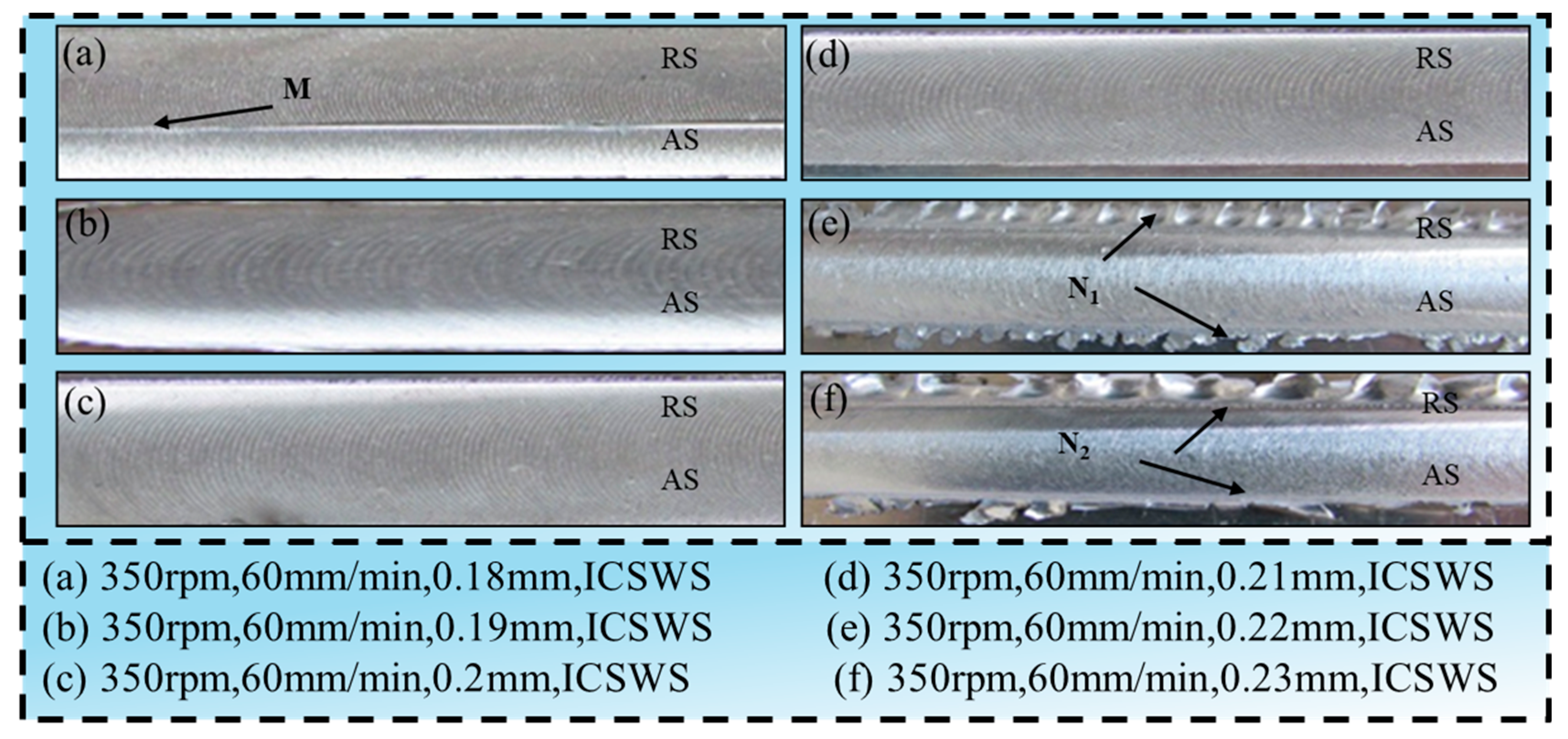
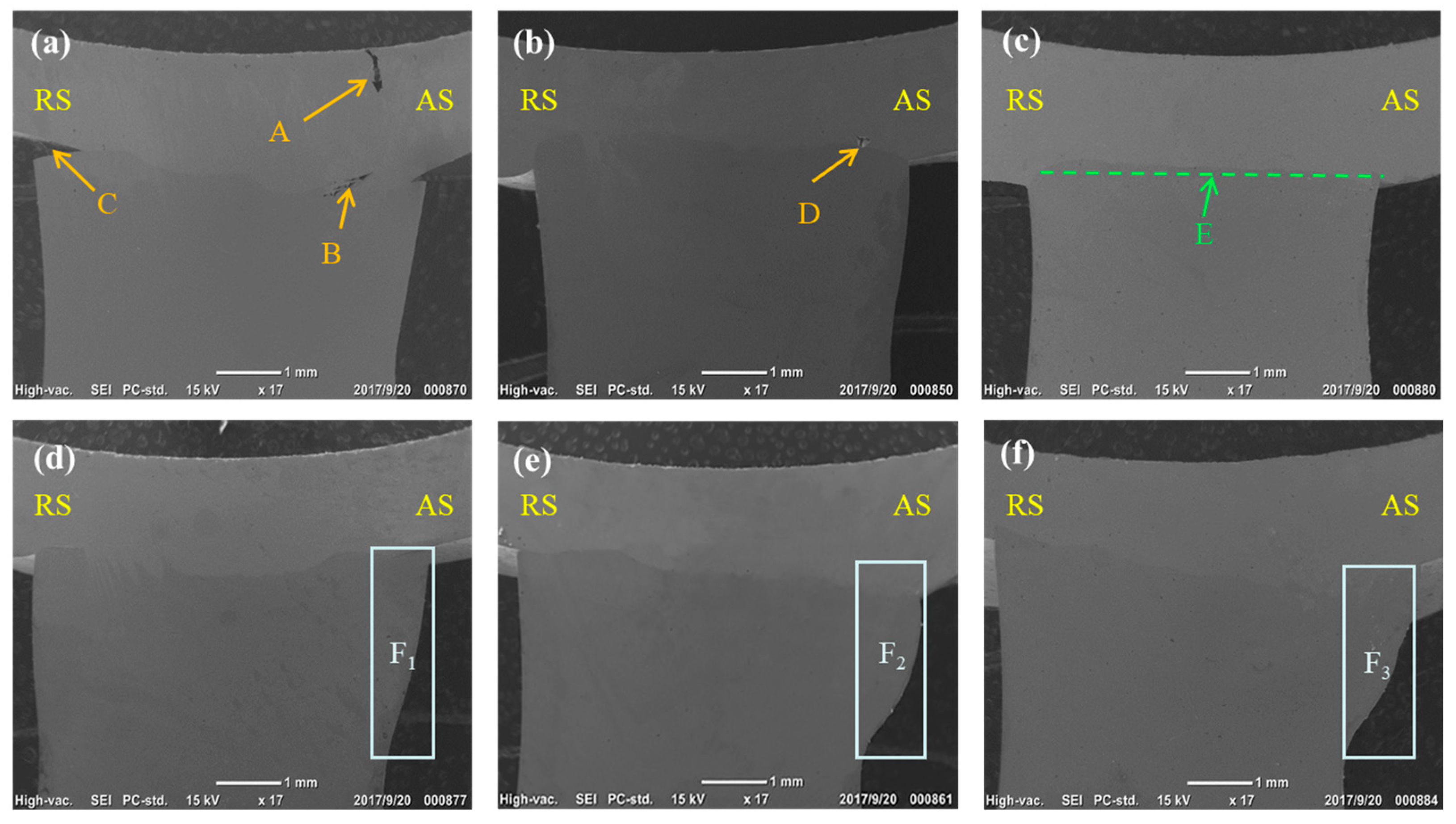
Figure 6 and Figure 7 depict the surface morphology and SEM images of T-joint welds obtained using the ICSWS structure at w = 350 rpm, v = 60 mm/min, and different insertion depths h. When h = 0.18 mm, grooves M appears on the joint surface (see Figure 6a), and grooves (point A), holes (point B), and gaps (point C) appear inside the joint AS (Figure 7). This is because h is too small, and insufficient heat input around the weld seam prevents adequate flow of plastic metal, thus failing to fill the cavities left behind by the welding pin during its advancement [34], further leading to incomplete penetration of the stringer section. With an increase in h to 0.19 mm, the surface formation is better compared to the former, with no grooves or channel holes present (see Figure 6b). However, channel holes appear at the root of the AS weld nugget (point D in Figure 7) because the heat generated by the axial shoulder is greater than that of the welding pin, and the heat generated by friction and plastic deformation of the welding pin is insufficient to plasticize the metal in this area, resulting in the formation of channel holes.
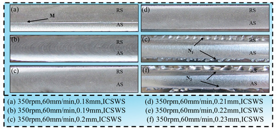
Figure 6.
Surface topography of local welds on T-joints under different h.
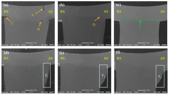
Figure 7.
SEM images of T-joints at (a) h = 0.18 mm, (b) h = 0.19 mm, (c) h = 0.2 mm, (d) h = 0.21 mm, (e) h = 0.22 mm, and (f) h = 0.23 mm.
When h is 0.2 mm or 0.21 mm, both the surface and internal formation of the weld are good, as revealed in Figure 6c,d and Figure 7c,d. When h increases to 0.22 mm or 0.23 mm, a large number of flashes N1 and N2 appear on the joint surface (see Figure 6e,f), while the internal formation is better, but the stringer protrudes significantly (see Figure 7e,f). This is because an excessively large insertion depth h results in excessive heat input to the RS of the T-joint, leading to excessive plasticization and significant stringer protrusion.
Based on the comprehensive analysis above, shoulder structure is ICSWS, under the combination of w is 350 rpm, v is 60 mm/min, and h is 0.2 mm or 0.21 mm, good surface and internal formation of T-joints can be achieved.
3.1.2. Tensile Test
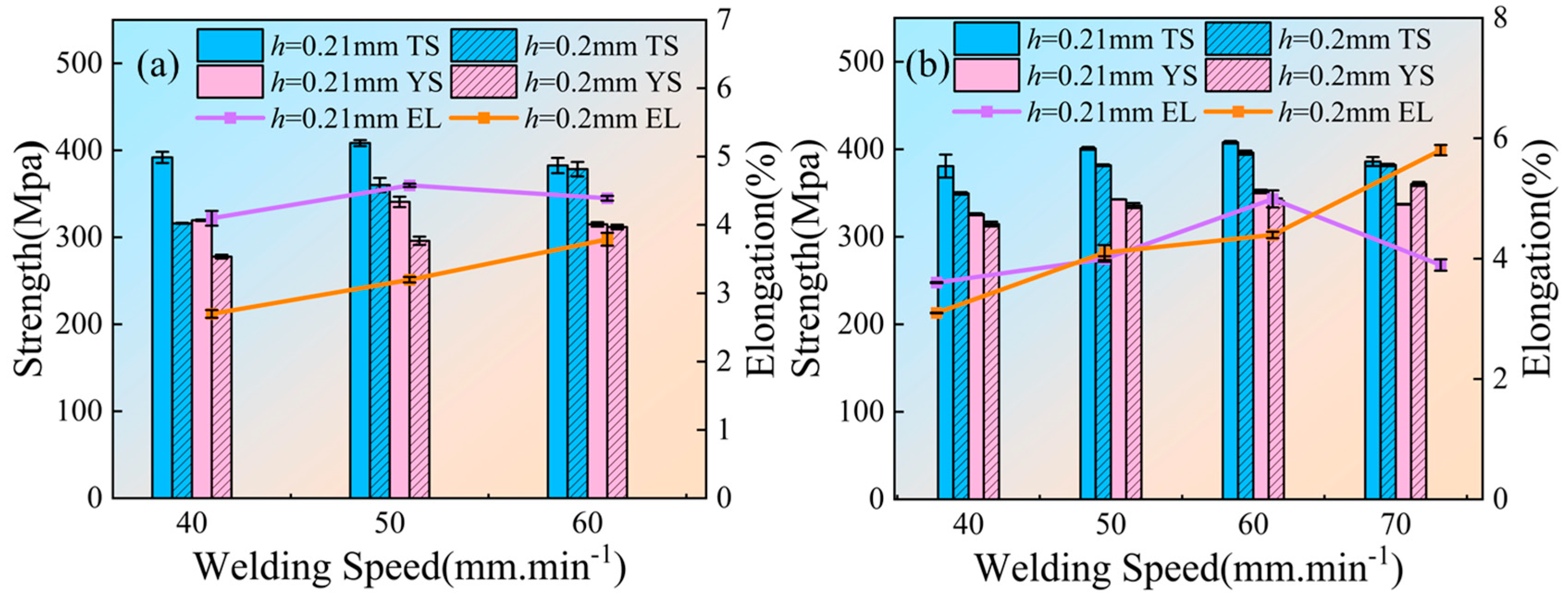
Based on the surface and internal morphology results presented above, the weld morphologies are favorable for specimens with the ICSWS shoulder structure under the parameter combinations of [350 rpm, 40~70 mm/min, 0.21 mm], [300 rpm, 40~60 mm/min, 0.21 mm] and [350 rpm, 60 mm/min, 0.20~0.21 mm]. Accordingly, tensile testing was performed on specimens with the parameter combinations [350 rpm, 40~70 mm/min, 0.20~0.21 mm] and [300 rpm, 40~60 mm/min, 0.20~0.21 mm], with the tensile results shown in Figure 8. As seen from Figure 8a, when w = 300 rpm, the tensile strength (TS), the yield strength (YS), and the elongation (EL) of the joint with h = 0.2 mm increase with the increase in welding speed v, while the TS, YS, and EL of the joint with h = 0.21 mm show a trend of first increasing and then decreasing with v. Clearly, the mechanical performance of the joint with h = 0.21 mm is superior to that of h = 0.2 mm. Further analysis reveals that when v = 50 mm/min, TS, YS, and EL reach their maximum values at 410 MPa, 341 MPa, and 4.6%, respectively.
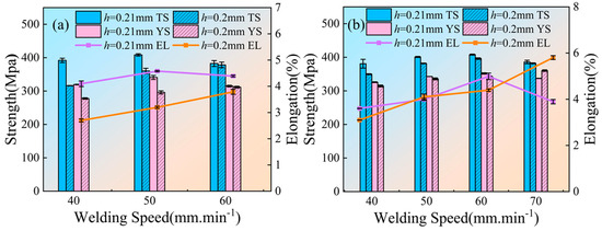
Figure 8.
Variation curves of strengths and elongation for T-joints with welding speed at (a) w = 300 rpm and (b) w = 350 rpm.
From Figure 8b, it can be observed that when w = 350 rpm, the YS and EL of the joint with h = 0.2 mm increase with the increase in v, while its TS initially increases and then decreases. Conversely, the TS, YS, and EL of the joint with h = 0.21 mm increase and then decrease with welding speed v. It is evident that the mechanical performance of the joint with h = 0.21 mm is superior to that of h = 0.2 mm. Further analysis reveals that when v = 60 mm/min and h = 0.21 mm, there is sufficient plastic flow and dynamic recrystallization of the material in the weld zone, leading to an improvement in the quality of the T-joint [35]. At this point, the joint’s TS, YS, and EL reach their maximum values, at 408 MPa, 352 MPa, and 5%, respectively. When v increases to 70 mm/min, the YS and EL of the joint with h = 0.2 mm are 360 MPa and 5.8%, respectively, higher than the YS (337 MPa) and EL (3.9%) of the joint with h = 0.21 mm. However, the corresponding TS (381 MPa) is slightly lower than the TS of h = 0.21 mm (386 MPa). This may be due to the excessively fast welding speed, resulting in relatively reduced heat input and insufficient plastic flow of the material in the weld zone [14].
In conclusion, reasonable values of w, v, and h not only affect the surface morphology of the joint but also directly impact its tensile properties. From the analysis of mechanical performance results, the optimal welding parameter combination for preparing T-shaped stiffened plate is w = 350 rpm, v = 60 mm/min, h = 0.21 mm, achieving the highest values of TS, YS, and EL for the joint at 408 MPa, 352 MPa, and 5%, respectively. Here, the tensile strength reaches 68.0% and 71.6% of the base materials 7055-T61 and 2197-T8, respectively.
3.2. Microstructural Features
3.2.1. Microstructural Evolution
Under the action of heat input, the heat source of the T-joint can be divided into the following zones in order of distance from the centerline of the plate thickness: the NZ, the thermomechanical affected zone (TMAZ), the heat affected zone (HAZ), and the base metal zone (BM). At the two arc angles, there is a welding juncture zone (WJZ). The microscopic morphology image is shown in Figure 9.

Figure 9.
Microscopic morphology image of the T-joint.
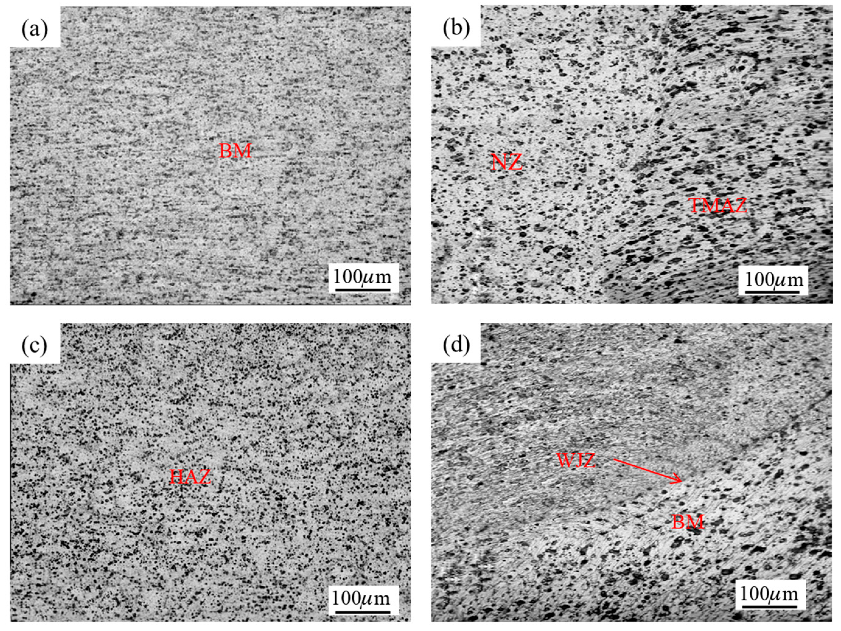
To study the typical organizational morphology of different regions in T-joints, T-shaped stiffened panels were welded using the ICSWS structure with a process parameter combination of [350 rpm, 60 mm/min, 0.21 mm], and their microstructure is shown in Figure 10. Upon observing Figure 10a, it is noticed that the 7055-alloy BM exhibits a flat and uniformly distributed structure, with black strengthening phase particles dispersed throughout the matrix, contributing to the T-joint’s favorable mechanical properties. In Figure 10b, there is a clear boundary between the NZ and the TMAZ. This is because the TMAZ structure experiences evident plastic flow traces due to shear stress from the stirring tool, and the welding heat cycle generated by stirring causes the NZ structure to undergo high temperature and intense plastic deformation, leading to dynamic recrystallization and the formation of fine equiaxed grains [36,37]. The HAZ does not undergo deformation due to the effect of welding heat conduction, but its strengthening phase and grain size are coarser than those of the BM, as seen in Figure 10c. It is evident from Figure 10d that a WJZ exists. On the upper side of the WJZ are finely equiaxed grains of the NZ, while on the lower side, closer to the 2197 alloy region, the grains exhibit various morphologies. Near the WJZ are larger equiaxed grains, followed by elongated grains, and those closer to the 2197 alloy BM are elongated grains.
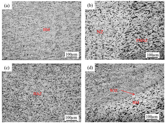
Figure 10.
Microstructure of different regions on the T-joints: (a) BM, (b) NZ and TMAZ, (c) HAZ, (d) WJZ and BM.
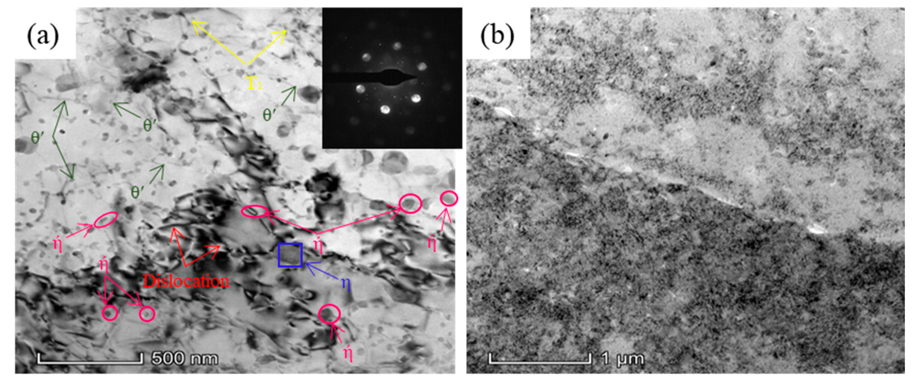
To further investigate the microstructural changes in NZ, Figure 11 shows the selected area electron diffraction (SAED) patterns recorded along the <011> TEM organization and parallel to the <011> Al strip axis of the electron beam along the <011> direction. The intra-granular precipitation phase significantly affects dislocation motion. Finer and more uniformly distributed precipitates hinder dislocation movement, thereby enhancing the alloy’s strength and hardness. It is generally believed that the precipitation sequence of precipitates in 7055 alloys is as follows: α (oversaturated solid solution) → GP zone → η’ phase (MgZn2) → η phase (MgZn2), where the η’ phase is metastable and serves as the primary source of strengthening for aluminum-based materials. When the plate-like η phase dominates, it signifies a decrease in strength [38].
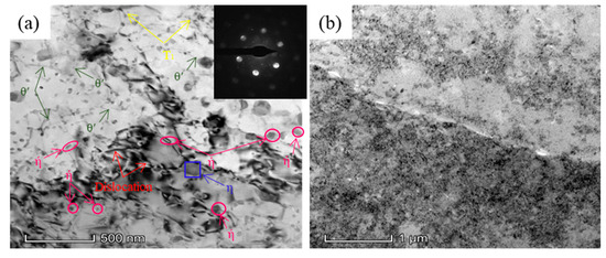
Figure 11.
Precipitation phase morphology in the NZ of the T-joints: (a) intra-granular precipitation phase (b) grain boundary precipitation phase.
From Figure 11a, it can be observed that a small number of dislocations are detected in NZ, with abundant needle-shaped phases θ’(Al2CuMg), inclined to cross needle-shaped phase T1(Al2CuLi), pancake or rod-shaped phase η’ (MgZn2), and plate-like phase η (MgZn2) already precipitated. These precipitation-strengthening phases (metastable η phase) impede dislocation motion, thereby reinforcing the matrix and endowing NZ with higher strength and hardness. The Cu/Li ratio in the studied region of 2197-T8 alloy is 1.92 (<2), and its precipitation process of precipitates involves α (oversaturated solid solution) → G.P. zone + δ’(Al3Li) → T1 + δ’ + θ’ → T1. During the welding process of the two dissimilar alloys in NZ, since the welding temperature can reach the solidus temperature, the initial δ’ (Au3Au) and θ’ phases re-dissolve into the solid solution. After welding, cooling causes the solid solution to decompose again, resulting in the precipitation of a small amount of inclined-crossing needle-shaped T1 phase (highlighted in yellow in the figure) and abundant needle-shaped θ’ phase. Therefore, NZ represents a combined reinforcement of θ’, T1, and η, enhancing the strength and hardness of the joint.
The arrangement, quantity, and cleanliness of grain boundary precipitates (segregation, precipitation-free zones (PFZ) width, equilibrium phase precipitation, and coarsening) affect intergranular movement, thus influencing the material’s plasticity properties. As shown in Figure 11b, grain boundaries typically serve as preferential nucleation and growth sites for precipitates. Under the high-temperature conditions within the NZ, newly formed fine precipitates emerge along these grain boundaries. These precipitates are typically smaller and exhibit more dispersed, discontinuous distribution compared to grain boundary precipitates in the BM. The finely dispersed precipitates effectively suppress grain coarsening, thereby further enhancing the mechanical strength of the joint.
3.2.2. Tensile Fracture Morphology
For all T-joints, the post-welding elongation exhibits a sharp decline compared to the BM. The tensile fracture consistently occurs at the corner between the skin and stringer, where insufficient material flow creates a weak zone. During tensile testing, stress concentration and rapid fracture develop at this corner with minimal deformation in other regions.
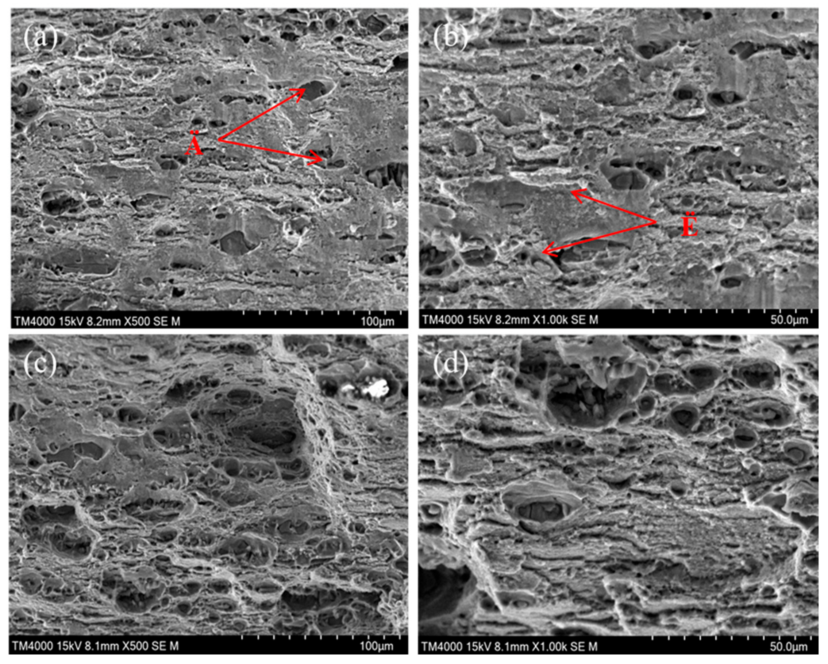
Fracture analysis was conducted on joints welded with parameter combination Ï = [300 rpm, 50 mm/min, 0.21 mm] and optimal parameter combination Ü = [350 rpm, 60 mm/min, 0.21 mm], as illustrated in Figure 12. The natural tensile fracture process revealed characteristic fracture features including dimple-like, river-like, beach-like, and rock-like morphologies. Scanning Electron Microscope (SEM) images in Figure 12 demonstrate that all fracture surfaces exhibit dimple features, confirming ductile fracture behavior.
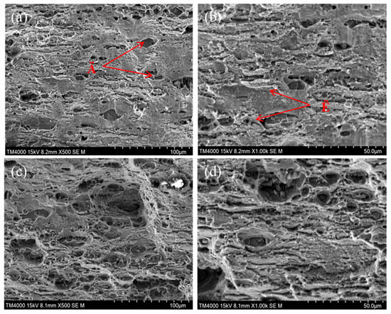
Figure 12.
Tensile fracture morphology of T-joints with different multiples and parameter combinations of Ï: (a) 500×, (b) 1000× and Ü (c) 500×, (d) 1000×.
From Figure 12, it can be observed that the fracture structure exhibits shear bands and dimples, along with tear ridges. Further observations from Figure 12a show a large relatively flat area on the section of the specimen, with fewer and shallower dimples. Part of the tear-like dimples forms obvious tear ridges (seen in the 1000× magnified image in Figure 12b). Moreover, from Figure 12c,d, it is evident that the number of dimples and tear ridges for the optimal parameter combination Ü is significantly more than that of Ï, and the depth of dimples is also greater than Ï. Greater depth and quantity of microscopic dimples, along with more tear ridges and longer lengths, correspond to higher strength and better plasticity on a macroscopic scale. This phenomenon aligns with the changes observed in macroscopic tensile properties, as demonstrated in Figure 8. Consequently, the primary fracture mode in the NZ of T-joints is ductile fracture [39]. The underlying mechanism lies in the FSW process where the NZ undergoes severe plastic deformation and dynamic recrystallization, resulting in significant grain refinement. The refined grains possess higher specific surface areas and increased grain boundaries, which effectively impede crack propagation and enhance the joint’s plastic deformation capacity. When subjected to external forces, fine dispersions of θ′/T1/η′ precipitates within the NZ grains and along grain boundaries. These hard, brittle particles act as primary sites for microvoid nucleation. During plastic deformation, decohesion at the matrix-precipitate interface or fracture of the precipitates themselves initiates the voids, which then grow and coalesce to form the characteristic dimples seen in Figure 12d. Meanwhile, the high density of grain boundaries provides numerous nucleation sites for microvoids, leading to this characteristic ductile fracture morphology. In short, due to the homogeneous microstructure and fine grain size in the NZ, the nucleation and coalescence of microvoids occur relatively uniformly. This produces finer, densely distributed dimples that collectively manifest as the signature dimple fracture morphology on the fracture surface.
3.3. Microhardness Test
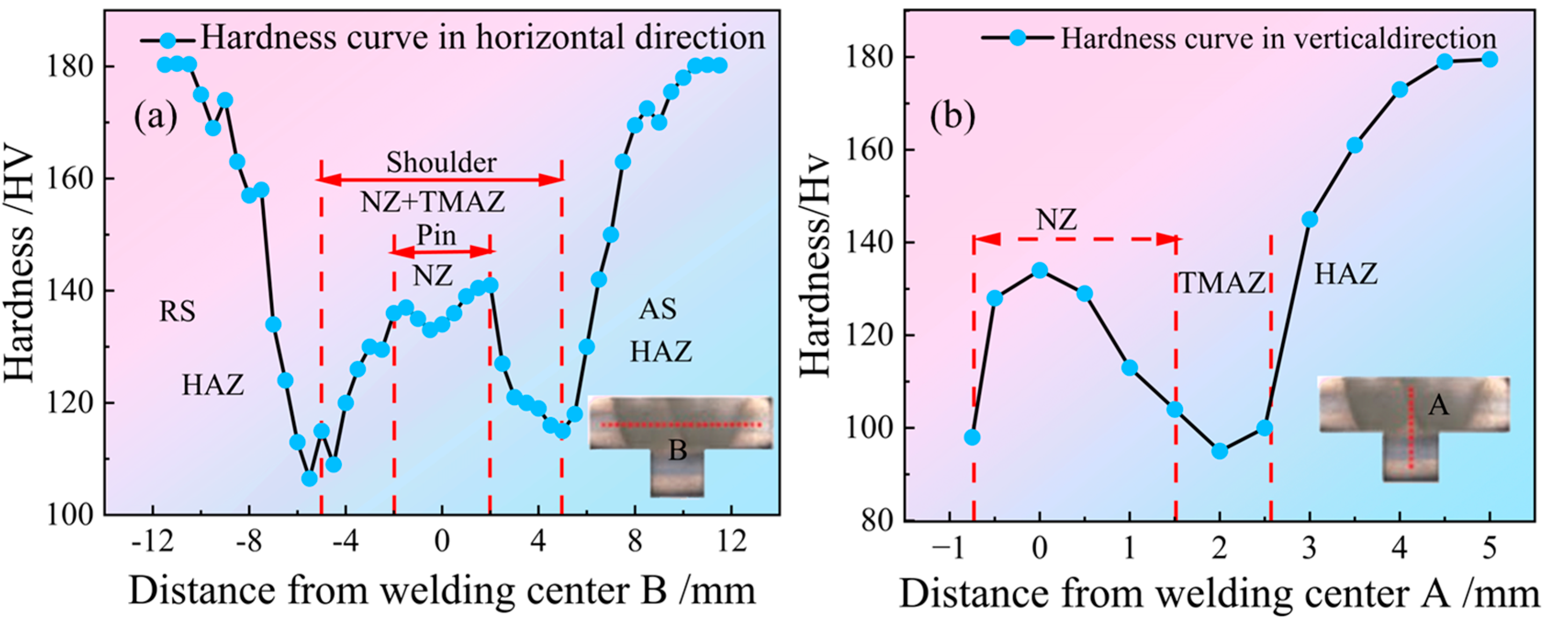
Due to the effects of stirring friction and heat input, the strength and hardness of the four regions (NZ, TMAZ, HAZ, and BM) in the T-joint vary, with higher hardness indicating better resistance to deformation. The hardness distribution under the optimal parameters (w = 250 rpm, v = 60 mm/min, h = 0.21 mm) is shown in Figure 13.
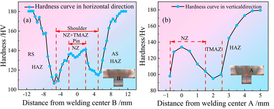
Figure 13.
Hardness distribution of T-joints along both sides of weld at w = 250 rpm, v = 60 mm/min, and h = 0.21 mm (a) center lines A, (b) center lines B.
As depicted in Figure 13a, the T-joint exhibits a “W” distribution pattern along the centerline B of the weld. The HAZ located beneath the shoulder is only affected by welding heat conduction, causing the aggregation and dissolution of strengthening phase particles, resulting in the most significant softening and lowest hardness in this region, with a microhardness of 106.5 Hv. The closer to the centerline B of the weld, the greater the hardness. This is because the welding heat cycle generated by stirring leads to high temperatures and intense plastic deformation in this area, resulting in dynamic recrystallization and the formation of finely equiaxed grains. This is related to the precipitation behavior in the NZ, as shown in Figure 11. Additionally, it is observed that the AS in the NZ has slightly higher hardness than the RS, attributed to the increased grain deformation in the AS, leading to the intensification of work hardening.
Observing Figure 13b, along the centerline A of the weld, the T-joint exhibits a “Z” distribution pattern. In particular, the surface of the NZ located beneath the shoulder experiences significant heat input, causing extensive dissolution of strengthening phases and the formation of a low-hardness zone. Additionally, the hardness near the TMAZ is lower than that on the surface of the NZ, attributed to the combined effects of the partial dissolution of strengthening phases and the coarsening of the microstructure, resulting in the lowest hardness in this region.
4. Conclusions
Based on the design of specialized fixtures, this study successfully welded T-joints composed of 7055-T61Al alloy and 2197-T8Al-Li alloy through FSW technology. A detailed analysis was conducted on the effects of tool geometry, w, v, and h on the macroscopic morphology, microstructure, and mechanical properties of the T-joints, providing theoretical insights for practical applications. The main research findings are as follows:
- (1)
- The ICSWS shoulder structure produces superior T-joint morphology with fewer weld defects compared to ICSWOS. Its spiral design reduces the actual contact area, leading to increased normal pressure and concentrates strain under identical axial downward force, thereby generating greater frictional and plastic deformation heat input.
- (2)
- Defect-free T-joints are achieved at w = 350 rpm, v = 60 mm/min, h = 0.21 mm, with simultaneous peak values of YS (352 MPa), TS (408 MPa), and EL (5%). The TS reaches 68.0% and 71.6% of base materials 7055-T61 and 2197-T8, respectively. Tensile specimens exhibit ductile fracture characterized by abundant deep dimples and elongated tear ridges on fracture surfaces—consistent with macroscopic tensile property trends.
- (3)
- According to the heat source distribution in the T-joint based on the distance from the centerline of the plate thickness, it can be divided into NZ, TMAZ, HAZ, and BM, with a WJZ between TMAZ and HAZ. Further research on the microstructure changes in NZ indicates the precipitation of θ′, T1, η′, and η phases. Simultaneously, newly formed fine precipitates emerge along grain boundaries, characterized by their significantly reduced size and more dispersed, discontinuous distribution. These finely dispersed precipitates effectively inhibit grain coarsening, thereby further enhancing the mechanical strength of the joint.
- (4)
- The microhardness in the NZ correlate with precipitated phases. And along the centerline B of the weld, the T-joints exhibit a “W” distribution pattern, with the HAZ beneath the axis shoulder having the lowest hardness (106.5 Hv). Along the centerline A of the weld, the T-joints exhibit a “Z” distribution pattern, with the lowest hardness near the TMAZ.
Author Contributions
Y.H.: writing—original draft. D.Z.: review & editing. T.X.: methodology. G.M.: software. S.F.: investigation. H.F.: data curation. Z.C.: formal analysis. W.L.: conceptualization. All authors have read and agreed to the published version of the manuscript.
Funding
This work was supported by the Sichuan Province Engineering Technology Research Center of General Aircraft Maintenance (Grant No. GAMRC2023ZD03), and the Fundamental Research Funds for the Central Universities (NO. 25CAFUC04018).
Data Availability Statement
The data will be available on request.
Acknowledgments
The experiment was developed by Key Laboratory of Friction Welding Technologies (KLFWT), which is managed by Materials Department of Northwestern Polytechnic University, C.H.N. The authors are also grateful to the NPU’s Analysis and Test Center for a test techniques and equipment.
Conflicts of Interest
The authors declare no conflict of interest.
References
- Li, L.; Meng, X.; Huang, S.; Wang, H.; Li, P.; Zhou, J. Investigating the effect of the scanning speed on the characteristics of Al-Li alloy fabricated by selective laser melting. J. Manuf. Process. 2022, 75, 719–728. [Google Scholar] [CrossRef]
- Wu, G.; Sun, J.; Zhang, L.; Ding, W. Current status and prospects of research and application of aluminum-lithium alloy. Nonferr Met. Sci. Eng. 2019, 10, 31–46. [Google Scholar]
- Tian, S.; Shang, J.; Gai, P.T. Numerical simulation and deformation prediction of stress peen forming for integrally stiffened panels. Acta Aeronaut. Astronaut. Sin. 2019, 40, 279–291. [Google Scholar]
- Jesus, J.; Costa, J.; Loureiro, A.; Ferreira, J. Fatigue Strength Improvement of GMAW T-welds in AA 5083 by Friction-Stir Processing. Int. J. Fatigue 2017, 97, 124–134. [Google Scholar] [CrossRef]
- Rhodes, C.G.; Mahoney, M.W.; Bingel, W.H.; Spurling, R.A.; Bampton, C.C. Effects of friction stir welding on microstructure of 7075 aluminum. Scr. Mater. 1997, 36, 69–75. [Google Scholar] [CrossRef]
- Zuo, D.Q.; Cao, Z.Q.; Cao, Y.J.; Huo, L.B.; Li, W.Y. Thermal fields in dissimilar 7055 Al and 2197 Al-Li alloy FSW T-joints: Numerical simulation and experimental verification. Int. J. Adv. Manuf. Technol. 2019, 103, 3495–3512. [Google Scholar] [CrossRef]
- Li, J.; Shen, Y.; Hou, W.; Qi, Y. Friction stir welding of Ti-6Al-4V alloy: Friction tool, microstructure, and mechanical properties. J. Manuf. Process 2020, 58, 344–354. [Google Scholar] [CrossRef]
- Yuvaraj, K.; Varthanan, P.A.; Haribabu, L.; Madhubalan, R.; Boopathiraja, K. Optimization of FSW tool parameters for joining dissimilar AA7075-T651 and AA6061 aluminium alloys using Taguchi Technique. Mater. Today Proc. 2021, 45, 919–925. [Google Scholar] [CrossRef]
- Kaushik, P.; Dwivedi, D.K. Effect of tool geometry in dissimilar Al-Steel Friction Stir Welding. J. Manuf. Process. 2021, 68 Pt B, 198–208. [Google Scholar] [CrossRef]
- Goel, P.; Siddiquee, A.N.; Khan, N.Z.; Hussain, M.A.; Khan, Z.A.; Abidi, M.H.; Al-Ahmari, A. Investigation on the Effect of Tool Pin Profiles on Mechanical and Microstructural Properties of Friction Stir Butt and Scarf Welded Aluminium Alloy 6063. Metals 2018, 8, 74. [Google Scholar] [CrossRef]
- Burek, R.; Wydrzyński, D.; Sęp, J.; Więckowski, W. The effect of tool wear on the quality of lap joints between 7075 T6 aluminum alloy sheet metal created with the FSW method. Eksploat. Niezawodn. 2018, 20, 100–106. [Google Scholar] [CrossRef]
- Regensburg, A.; Schürer, R.; Weigl, M.; Bergmann, J.P. Influence of Pin Length and Electrochemical Platings on the Mechanical Strength and Macroscopic Defect Formation in Stationary Shoulder Friction Stir Welding of Aluminium to Copper. Metals 2018, 8, 85. [Google Scholar] [CrossRef]
- Li, D.; Zhang, B.; Zhang, J.; Liu, S.; Jiang, K.; Yang, X. Microstructure characteristics, static and fatigue properties of additive FSW T-joint of 6061 alloy. Trans. China Weld. Inst. 2021, 42, 62–68+91+100. [Google Scholar]
- Ajri, A.; Rohatgi, N.; Shin, Y.C. Analysis of defect formation mechanisms and their effects on weld strength during friction stir welding of Al 6061-T6 via experiments and finite element modeling. Int. J. Adv. Manuf. Technol. 2020, 107, 4621–4635. [Google Scholar] [CrossRef]
- Frigaard, Ø.; Grong, Ø.; Midling, O.T. process model for friction stir welding of age harding aluminum alloy. Met. Mater. Trans. A 2001, 32, 1189–1200. [Google Scholar] [CrossRef]
- Zareie, O.; Mousavizade, S.M.; Ezatpour, H.R.; Zareie, H.; Farmanbar, N. Effect of plunging depth and dwelling time on microstructure and mechanical properties of 6061 aluminum alloy welded by protrusion friction stir spot welding. Weld. World 2020, 64, 785–805. [Google Scholar] [CrossRef]
- Gao, S.; Zhou, L.; Zhang, X.; Zhang, J.; Li, G.; Zhao, H. Microstructure and properties of friction stir welded joints for 6061-T6/7075-T6 dissimilar aluminum alloy. Trans. China Weld. Inst. 2022, 43, 35–42. [Google Scholar]
- Shi, L.; Wu, C.; Jiang, Y.; Gao, S.; Fu, L. Microstructure and mechanical properties of 2195-T6 Al–Li alloy joint prepared by friction stir welding. Trans. China Weld. Inst. 2022, 43, 25–34. [Google Scholar]
- Vidakis, N.; Petousis, M.; David, C.; Sagris, D.; Mountakis, N.; Moutsopoulou, A. The impact of process parameters and pin-to-shoulder ratio in FSW of polycarbonate: Welding forces and critical quality indicators. Int. J. Adv. Manuf. Technol. 2024, 130, 5457–5477. [Google Scholar] [CrossRef]
- Liu, H.; Gao, Y.; Zhang, Q.; Zhao, H. Microstructure and mechanical properties of friction stir welded joint of 2A14-T4 aluminum alloy thick plate. Trans. China Weld. Inst. 2022, 43, 20–24. [Google Scholar]
- Yang, H.; Zhao, H.; Xu, X.; Zhou, L.; Zhao, H.; Liu, H. Effect of Stirring Pin Rotational speed on Microstructure and Mechanical Properties of 2A14-T4 Alloy T-Joints Produced by Stationary Shoulder Friction Stir Welding. Materials 2021, 14, 1938. [Google Scholar] [CrossRef] [PubMed]
- Thomae, M.; Gester, A.; Wagner, G. Comparison of process behavior, microstructure and mechanical properties of ultrasound enhanced friction stir welded titanium/titanium joints. Weld. World 2022, 66, 1131–1140. [Google Scholar] [CrossRef]
- Su, Y.; Li, W.; Liu, X.; Gao, F.; Yu, Y.; Vairis, A. Evolution of microstructure, texture and mechanical properties of special friction stir welded T-joints for an alpha titanium alloy. Mater. Charact. 2021, 177, 111152. [Google Scholar] [CrossRef]
- Raj, S.; Biswas, P. Experimental investigation of the effect of induction preheating on the microstructure evolution and corrosion behaviour of dissimilar FSW (IN718 and SS316L) joints. J. Manuf. Process 2023, 95, 143–159. [Google Scholar] [CrossRef]
- Jesus, J.; Costa, J.; Loureiro, A.; Ferreira, J. Assessment of Friction Stir Welding Aluminium T-Joints. J. Mater. Process Technol. 2018, 255, 387–399. [Google Scholar] [CrossRef]
- Zuo, D.; Cao, Z.; Cao, Y.; Zheng, G. Effect of pre-stretching on microstructures and mechanical behaviors of creep-aged 7055 Al alloy and its constitutive modeling. Metals 2019, 9, 584. [Google Scholar] [CrossRef]
- Zuo, D.; Cao, Z.; Cao, Y.; Zheng, G. Research on theoretical modeling and numerical simulation of viscoelastic-plastic bending neutral layer in T-welding stiffened panels-based aged stress relaxation forming. Proc. Inst. Mech. Eng. Part C J. Mech. Eng. Sci. 2020, 234, 2881–2894. [Google Scholar] [CrossRef]
- Lu, L.; Xue, W.B.; Jin, X.Y.; Du, J.C.; Li, Y. Surface protection of friction stir welding joint of 5083 aluminum alloy by micro-arc oxidation. Trans. Mater. Heat Treat. 2011, 32, 140–144. [Google Scholar]
- Manuel, N.; Costa, J.M.; Loureiro, A. Effect of Material Properties and Process Parameters on Morphology and Strength of Friction-Stir-Welded Dissimilar T-Joints. J. Mater. Eng. Perform. 2019, 28, 5233–5244. [Google Scholar] [CrossRef]
- Kasirajan, T.; Ravindran, R.; Ramkumar, T.; Selvakumar, M. Investigation of the microstructural, mechanical, and thermal evolution of dissimilar aluminium alloys during friction stir welding. Trans. Can. Soc. Mech. Eng. 2020, 44, 38–48. [Google Scholar] [CrossRef]
- Ghangas, G.; Singhal, S. Influence of Process Parameters on Mechanical and Microstructural Property of Dissimilar Friction Stir Welded Joints of Armor Aluminium Alloys AA7039 and AA5083. Indian J. Eng. Mater. Sci. (IJEMS) 2022, 29, 686–695. [Google Scholar]
- GB/T2651—2008; General Administration of Quality Supervision, Inspection and Quarantine of the People’s Republic of China, Standardization Administration of China. Tensile Test Method of Welded Joints; Standards Press of China: Beijing, China, 2008; p. 8.
- Burek, R.; Wydrzyński, D.; Kubit, A.; Łogin, W. The influence of the shoulder depth on the properties of the thin sheet joint made by FSW technology. Aircr. Eng. Aerosp. Technol. 2020, 93, 120–126. [Google Scholar] [CrossRef]
- Du, S.; Liu, H.; Jiang, M.; Hu, Y.; Zhou, L. Eliminating the cavity defect and improving mechanical properties of TA5 alloy joint by titanium alloy supporting friction stir welding. J. Manuf. Process 2021, 69, 215–222. [Google Scholar] [CrossRef]
- Gangwar, K.; Ramulu, M. Friction stir welding of titanium alloys: A review. Mater. Des. 2018, 141, 230–255. [Google Scholar] [CrossRef]
- Abbasi, M.; Bagheri, B.; Sharifi, F. Simulation and experimental study of dynamic recrystallization process during friction stir vibration welding of magnesium alloys. Trans. Nonferrous Met. Soc. China 2021, 31, 2626–2650. [Google Scholar] [CrossRef]
- Hou, W.; Shen, Z.; Huda, N.; Oheil, M.; Shen, Y.; Jahed, H.; Gerlich, A.P. Enhancing metallurgical and mechanical properties of friction stir Butt welded joints of Al–Cu via cold sprayed Ni interlayer. Mater. Sci. Eng. A 2021, 809, 140992. [Google Scholar] [CrossRef]
- Zuo, J.; Hou, L.; Shi, J.; Cui, H.; Zhuang, L.; Zhang, J. Effect of deformation induced precipitation on grain refinement and improvement of mechanical properties AA 7055 aluminum alloy. Mater. Charact. 2017, 130, 123–134. [Google Scholar] [CrossRef]
- Yuk, S.; Shim, S.H.; Jeong, M.; Lee, D.; Lee, K.; Kim, S.H.; Lee, S.Y.; Han, J.H. Micro/nanostructure evolution and deformation mechanisms in friction-stir-welded 7075 Al alloy: A comparative analysis of weld zones. J. Mater. Res. Technol. 2025, 36, 5193–5210. [Google Scholar] [CrossRef]
Disclaimer/Publisher’s Note: The statements, opinions and data contained in all publications are solely those of the individual author(s) and contributor(s) and not of MDPI and/or the editor(s). MDPI and/or the editor(s) disclaim responsibility for any injury to people or property resulting from any ideas, methods, instructions or products referred to in the content. |
© 2025 by the authors. Licensee MDPI, Basel, Switzerland. This article is an open access article distributed under the terms and conditions of the Creative Commons Attribution (CC BY) license (https://creativecommons.org/licenses/by/4.0/).

