Article

Second-Order Complex-Coefficient Flux Observer with Stator Resistance Estimation for Induction Motor Sensorless Drives

School of Mechanical Science and Engineering, Huazhong University of Science and Technology, Wuhan 430074, China
*
Author to whom correspondence should be addressed.
Machines 2025, 13(9), 845; https://doi.org/10.3390/machines13090845
Submission received: 18 August 2025 / Revised: 6 September 2025 / Accepted: 8 September 2025 / Published: 11 September 2025
(This article belongs to the Section Electrical Machines and Drives)

Abstract

The voltage model (VM) is widely used in sensorless induction motor drives owing to its structural simplicity and speed-independence. However, DC offsets in back electromotive force (BEMF) caused by measurement errors can degrade the accuracy of flux and speed estimation. To address this issue, this article proposes a second-order complex-coefficient flux observer (SCFO) that effectively eliminates DC offsets without introducing phase delay and amplitude attenuation, while maintaining excellent dynamic performance. Furthermore, to enhance the robustness of the flux observer against stator resistance variations, an improved stator resistance adaptive law based on the rotating reference frame is proposed. Ultimately, experimental validation on a 1.5 kW induction motor drive platform confirms the effectiveness of the proposed sensorless scheme.

1. Introduction

In recent decades, induction motor drives have been widely applied in industrial applications. In conventional vector control systems, rotor speed and position are obtained through mechanical sensors [1]. This scheme inevitably increases the complexity of mechanical structures and raises installation costs. To address these issues, many sensorless drive schemes have been proposed over the past two decades [2,3,4].
For high-performance induction motor sensorless drives, accurate flux estimation is crucial. The voltage model is widely used to estimate flux, and it is mainly applied in the following two sensorless schemes. The first is the model reference adaptive system (MRAS), which uses the voltage model as the reference model [5]. The second scheme employs methods such as inverse tangent calculation or phase-locked loop (PLL) to estimate rotor position and speed based on the flux estimated by the voltage model [6,7,8]. The performance of both sensorless schemes in estimating rotor position and speed depends heavily on the voltage model. According to the structure of the voltage model, flux estimation can be obtained by integrating BEMF. However, in practice, BEMF often contains DC offsets caused by measurement and sampling errors. The pure integration calculation, which is not recommended in practical applications, will make the estimated flux unbounded owing to the DC offset. To address these issues, a series of improvement schemes for voltage model flux estimators have been proposed. Existing solutions can be roughly categorized based on the introduction of reference flux information into two types: the closed-loop flux observer, which introduces reference flux information, while the open-loop flux observer is designed based on the desired frequency-domain characteristics. The most representative scheme of the former is the combined voltage and current model flux observer [9]. The observer introduces the flux estimated by the current model as the reference flux into the voltage model. In [10], a nonlinear flux observer is proposed for PMSM sensorless control, which also requires reference flux. However, unlike the observer mentioned above, the nonlinear flux observer has a more straightforward structure, as it does not require trigonometric function operations. In [11], the reference flux is introduced into the flux observer through proportional closed-loop control. To further eliminate the DC offset, a flux trajectory center correction method is designed. In [12], an offset estimator is proposed that uses a parallel structure of two closed-loop flux observers. It is worth mentioning that this observer requires a reference flux as the initial value for flux estimation. Although the closed-loop observer mentioned above addresses the issues of flux estimation saturation and offset through closed-loop feedback, this type of flux observer still requires precise reference flux information. When the reference flux is inaccurate, the performance of the closed-loop flux observer may deteriorate. The improved pure integrator scheme, which does not require the reference flux, avoids the issues mentioned earlier. A conventional improved pure integrator scheme uses a low-pass filter (LPF) instead of the pure integrator. While the improved scheme can slightly suppress DC offset, it also introduces significant phase delay and amplitude attenuation when the operating frequency is below the cutoff frequency. In [13], a flux observer based on the first-order LPF with the LPF pole proportional to the stator frequency is proposed. However, the proposed schemes suffer from the deficiency of requiring complicated flux vector rotation and amplification calculations. Another popular method for improving pure integrator schemes is to use generalized integrators instead of pure integrators. Compared to LPF, generalized integrators do not require magnitude and phase compensation. In [14], a flux observer based on the second-order generalized integrator (SOGI) is proposed. In [15,16,17,18], different high-order generalized integrator-based improved flux observers are proposed. It is noteworthy that only generalized integrators of third-order or higher can effectively eliminate DC offset, whereas SOGI can only suppress it. Although increasing the generalized integrator’s order improves the capability to mitigate DC offset and harmonics, it also increases the complexity of the observer structure. In [19,20], A complex-coefficient flux observer (CFO) that utilizes the orthogonality between flux and BEMF is proposed. Although the structure of the CFO is simpler than most of the above flux observers, its ability to suppress DC offset is limited.
In sensorless vector control systems of induction motors, stator resistance mismatch can lead to flux estimation errors and field orientation errors, resulting in a decline in sensorless control performance and even stability issues in the system. Accurate stator resistance parameters are crucial for achieving high-performance sensorless vector control [21]. Traditional methods use the stator resistance estimated offline in the flux observer, but the actual stator resistance often changes due to the temperature rise caused by long-term motor operation. To address this issue, numerous studies have proposed online stator resistance identification methods based on full-order adaptive observers [22,23] and full-order sliding mode observers [24,25,26] combined with model reference adaptive laws. The coupling between speed and stator resistance estimation makes the sensitivity of stator resistance dependent on the performance of stator frequency estimation.
In this article, a novel second-order complex-coefficient flux observer (SCFO) for DC offset elimination is proposed. The designed SCFO has a bandpass frequency characteristic, which eliminates the DC offset while avoiding amplitude attenuation and phase lag in the fundamental component. The introduction of a complex coefficient structure reduces the order of the flux observer, with the designed observer having an order of 2, making it simpler and easier to implement compared to flux observers based on high-order generalized integrators. In addition, detailed performance analysis and discretization implementation are also provided. In addition, an improved stator resistance adaptive law based on the rotating reference frame is proposed. The designed adaptive law does not require the participation of the stator frequency, effectively decoupling the stator frequency estimation and stator resistance estimation.
The outline of this brief is structured as follows. In Section 2 the voltage model of the induction motor is given. In Section 3, the SCFO is proposed, and the stability and discretization of the SCFO are also discussed in this Section. In Section 4, a stator resistance estimator is proposed. In Section 5, comparative experiments are conducted to verify the effectiveness of the proposed methods. Finally, Section 6 concludes this article.

2. Model of Induction Motor

The mathematical model of inverse-Γ equivalent circuit of induction motor in the αβ reference frame can be given as
u s = R s i s + L σ p i s + R r i s - R r / L m I ψ r + ω r J ψ r p ψ r = R r i s - R r / L m I ψ r + ω r J ψ r
where u s = [ u α u β ] T , i s = [ i α i β ] T and ψ r = [ ψ r α ψ r β ] T are stator voltage vector, stator current vector, and rotor flux vector, respectively. Rs, Rr, Lm, Lσ are the stator resistance, rotor resistance, magnetizing inductance, and transient inductance, respectively. p is the differential operator symbol. ω r is the electrical rotor angular speed, pn is the number of pole pairs. According to (1), ψ r can be expressed as
ψ r = ( u s - R s i s - L σ p i s ) d t = e r d t
where e r is the BEMF vector. The above equation represents the traditional voltage-model flux observer.

3. Proposed Flux Observer

In this Section, the SCFO is proposed to overcome the shortcomings of conventional flux observers. The proposed observer can eliminate the DC offset and maintain excellent dynamic performance. The stability and discretization of SCFO are also discussed in this section.

3.1. Second-Order Complex-Coefficient Flux Observer

The traditional complex-coefficient filter [27], denoted as G c ( s ) , functions as a low-pass filter and is ineffective at eliminating DC offset. Although the high-pass filter G h ( s ) has a simple structure and can remove DC offset, it introduces both magnitude and phase errors in the frequency response at the fundamental frequency.
G c ( s ) = k c k c + s - j ω ^ f G h ( s ) = s s + ω c
where k c is gain of complex-coefficient filter, ω c is the cut-off frequency of conventional high-pass filters. To effectively eliminate DC offset in flux estimation, a series of complex-coefficient high-pass filters is designed by combining two conventional filters. G H P F maintains the same magnitude-frequency response as a pure integrator at the fundamental frequency while effectively eliminating DC offset.
G H P F = s L ( s ) s L ( s ) + N ( s ) ( k ω ^ f + j s k s i g n ( ω ^ f ) )
where k is the observer gain. HPF with distinct frequency characteristics can be acquired by setting diverse L(s) and N(s). By serially connecting the CFO with the designed HPF, the following flux observer can be obtained:
ψ SCFO ( s ) e r ( s ) = sL ( s ) sL ( s ) + N ( s ) ( k ω ^ f + jsksign ( ω ^ f ) ) 1 jksign ( ω ^ f ) s + k ω ^ f
To simplify the structure of the proposed flux observer, L(s) is set to unity. To extract the offset in the BEMF, N(s) is set to 1 / ( s + k ω ^ f ) . Substituting N ( s ) = 1 / ( s + k ω ^ f ) and L(s) = 1 into (5), the transfer function of the proposed SCFO can be given as
ψ SCFO ( s ) e r ( s ) = s ( 1 j k s i g n ( ω ^ f ) ) s ( s + k ω ^ f ) + j s k s i g n ( ω ^ f ) + k ω ^ f
The block diagrams of the proposed SCFO is shown in Figure 1.

3.2. Stability Analysis

The stability of the designed SCFO is analyzed through flux estimation error convergence, and ω ^ f > 0 is assumed to facilitate the stability proof. Define ψ r = e r / j ω f , where ψ r is the flux directly calculated from e r . Substituting ψ r into (6), one obtains
ψ S C F O ( s ) ψ r ( s ) = s ( 1 j k ) j ω f s ( s + k ω ^ f ) + j s k + k ω ^ f
Considering ψ S C F O = ψ ˜ r + ψ r , where ψ ˜ r is the difference between the flux estimated by the SCFO and ψ R , (7) can be expressed as
ψ ˜ r ( s ) + ψ r ( s ) ψ r ( s ) = s ( 1 jk ) j ω f s ( s + k ω ^ f ) + jsk + k ω ^ f
To derive the characteristic equation of the flux estimation error, one obtains
ψ ˜ r ( s ) ( s 2 + ( k ω ^ f + jk ) s + k ω ^ f ) = ψ r ( s ) ( s 2 + ( k ω ^ f + jk ) s + k ω ^ f j ω f s k ω f s )
When SCFO converges to the real motor system, substituting s = j ω ^ f and ω f = ω ^ f into (9), the rotor flux estimation error can be derived as
ψ ˜ R ( s ) ( s 2 + ( k ω ^ f + j k ) s + k ω ^ f ) = 0
The eigenvalues of (10) can be expressed as
c 1 , 2 = j k k ω ^ f ± ( j k + k ω ^ f ) 2 4 k ω ^ f 2
Since the observer gains k > 0, it can be deduced that R e ( ( j k + k ω ^ f ) 2 4 k ω ^ f ) < k ω ^ f . Therefore, the real parts of both eigenvalues are negative, which guarantees the convergence of the flux estimation error.

3.3. Performance Analysis

Analysis of DC component: When the DC component is used as input for the SCFO, the following can be obtained
ψ SCFO , dc ( s ) = s s ( 1 jksign ( ω ^ f ) ) s ( s + k ω ^ f ) + jksign ( ω ^ f ) + k ω ^ f e offset s
Through the terminal value theorem, flux estimation error can be described as
lim t ψ S C F O , d c ( t ) = lim s 0 s ψ SCFO , dc ( s ) = lim s 0 s s ( 1 jksign ( ω ^ f ) ) s ( s + k ω ^ f ) + jksign ( ω ^ f ) + k ω ^ f e offset s = 0
From (13), it can be indicated that the proposed flux observer can theoretically eliminate the DC offset.
(2) Analysis of fundamental component: substituting s = j ω ^ f into (6), it can be obtained as
G SCFO ( j ω ^ f ) = j ω ^ f + k ω ^ f ( - ω ^ f 2 + jk ω ^ f 2 × sign ( ω ^ f ) ) - k ω ^ f + k ω ^ f = 1 j ω ^ f
As shown in (14), the frequency domain response of the fundamental component of SCFO is consistent with that of the pure integrator.
(3) Analysis of higher-order harmonic component: substituting s = j h ω ^ f into (6), it can be obtained as
G SCFO ( jh ω ^ f ) = jh ω ^ f ( 1 - jksign ( ω ^ f ) ) - ( h ω ^ f ) 2 - hk ω ^ f + k ω ^ f + jhk ω ^ f ω ^ f
The magnitude response of flux estimation can be given as
h k 2 + 1 ( k - hk - h 2 ω ^ f ) 2 + ( kh ω ^ f ) 2
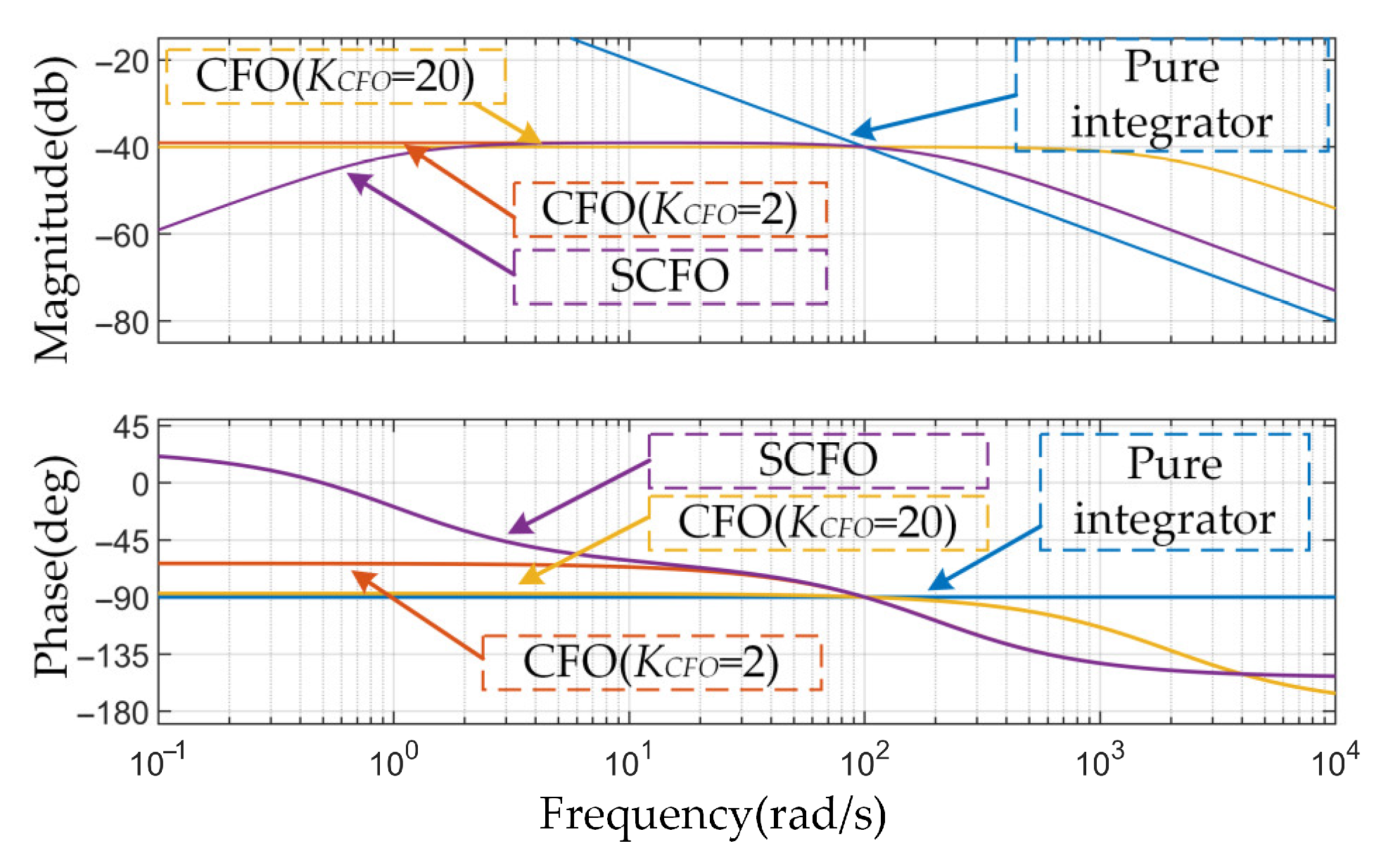
As shown in (16), the ability of the SCFO to suppress harmonics mainly depends on the gain k. The performance of SCFO in suppressing harmonics is comparable to that of the CFO, and the conclusion can also be derived from Figure 2, which presents the Bode diagrams of the pure integrator, SCFO, and CFO with different gains. In Figure 2, the center frequency is set to 100 rad/s, and the gains k of the SCFO are set to 2. From Figure 2, it can be concluded that the flux estimation of the pure integrator will saturate due to its infinite gain at zero frequency. The DC gain of the CFO will decrease as the observer gain increases, while this trade-off inevitably degrades its filtering performance. Compared to the aforementioned flux observer, the proposed SCFO exhibits a band-pass characteristic, enabling it to effectively eliminate the DC component. As evidenced by the Bode plot and performance analysis, increasing the observer gain accelerates the convergence speed of the DC offset estimation but reduces its ability to suppress higher-order harmonics. The gain only affects the convergence speed of the DC offset estimation, while the DC component in the flux estimation will eventually converge to zero. Therefore, since the primary focus is on the observer’s capability to suppress higher-order harmonics, the gain should not be set too high and is generally selected within the range of 1 to 5.

3.4. Discrete Implementation

The SCFO designed in the continuous domain requires discretization. This process is accomplished using the backward Euler method, and the corresponding block diagram is illustrated in Figure 3. The discretization of SCFO is categorized into two parts. The first part involves the discretization of the offset estimation, and the second part involves the discretization of the rotor flux estimation. The discretization processes are shown as follows.
e ^ offset ( i + 1 ) = e ^ offset ( i ) + T s k [ jsign ( ω ^ f ) ( e r ( i + 1 ) - e ^ offset ( i ) ) + ψ SCFO ( i ) ω ^ f ] ψ SCFO ( i + 1 ) = ψ SCFO ( i ) + T s [ - k jsign ( ω ^ f ) ( e r ( i + 1 ) - e ^ offset ( i ) ) - k ψ SCFO ( i ) ω ^ f + ( e r ( i + 1 ) - e ^ offset ( i + 1 ) ) ]
where Ts is the discretization period. To further demonstrate the advantages of the proposed method, the computational complexity of the four observers after applying the backward difference method is shown in Table 1.
Both the SCFO and the Third-order generalized integrator exhibit good DC offset suppression capability, but the SCFO has lower computational complexity. Pseudo-code for the discrete implementation of SCFO is presented as Appendix A.

3.5. Analysis of Parameter Perturbation on the SCFO

The ideal BEMF and the fundamental component of the BEMF considering parameter variations are expressed as follows:
e r   = u s - R s i s - L σ p i s e r , v = u s - ( R s + Δ R s ) i s - ( L σ + Δ L σ ) p i s
As can be seen from (14), the proposed SCFO exhibits identical frequency characteristics with the pure integrator at the fundamental frequency. Additionally, variations in stator resistance and leakage inductance are reflected only in the fundamental component of the BEMF. Therefore, the impact of parameter variations on the flux estimation of the proposed method can be expressed as follows:
ψ S C F O - ψ r = - Δ R s i s / j ω f - Δ L σ i s
In fact, for open-loop flux observers with frequency characteristics at the fundamental frequency identical to that of the pure integrator, such as CFO and SCFO, their sensitivity to stator resistance and leakage inductance is the same. The flux estimation errors caused by parameter deviations in these observers can be represented by (19). From the equation, it can be observed that at low speeds, the deviation of stator resistance has a significant impact on flux estimation, while at high speeds, the leakage inductance has a more pronounced effect.

4. Proposed Stator Resistance Estimator

The voltage equation of the induction motor in the rotating reference frame can be written as follows
u sd = L σ p i sd + R s i sd + p ψ rd - L σ ω e i sq - ω e ψ rq u sq = L σ p i sq + R s i sq + p ψ rq + L σ ω e i sd + ω e ψ rd
Through setting the derivative terms to zero, the steady-state voltage equations are derived as follows
u sd = R s i sd - L σ ω e i sq - ω e ψ rq u sq = R s i sq + L σ ω e i sd + ω e ψ rd
When the stator resistance is accurate, that is, when the field orientation is accurate, the following can be obtained
ψ rq = 0 ψ rd = L m i s d
Substituting (22) into (21) gives the following
u sd = R s i sd - L σ ω e i sq u sq = R s i sq + L σ ω e i sd + L m ω e i sd
The reference model of the traditional active power model is the dot product of the stator voltage vector and the stator current vector. However, when applying this reference model, it inevitably leads to the presence of stator frequency terms in the adjustable model. Therefore, an improved reference model can be designed as follows.
Ref = L σ u s q i s q / L s + u s d i s d
Substituting (23) into the above equation, the adjustable model in the model reference adaptive system can be obtained as follows:
Adj = L σ R s i sq 2 / L s + R s i sd 2
From the above equation, it can be seen that the stator frequency does not appear in the adjustable model, thereby achieving the decoupling between stator frequency estimation and stator resistance estimation. When applying the PI adaptive law, the stator resistance adaptive rate can be written as follows:
R ^ s = k p + k i p L σ u s q i s q / L s + u s d i s d L σ R s i sq 2 / L s R s i sd 2
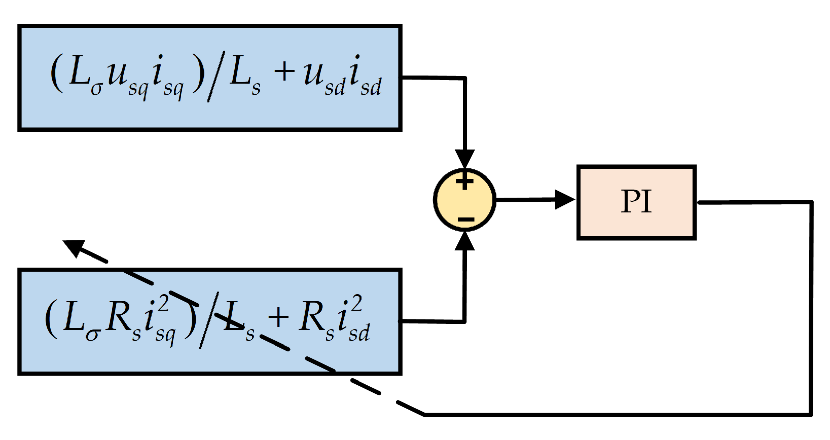
Block diagram of the stator resistance estimator is shown in Figure 4. It is noteworthy that, considering that the proportional gain may introduce noise into the estimation, the proportional gain is often set to 0, with only the integral gain being adjusted.

5. Experimental Results

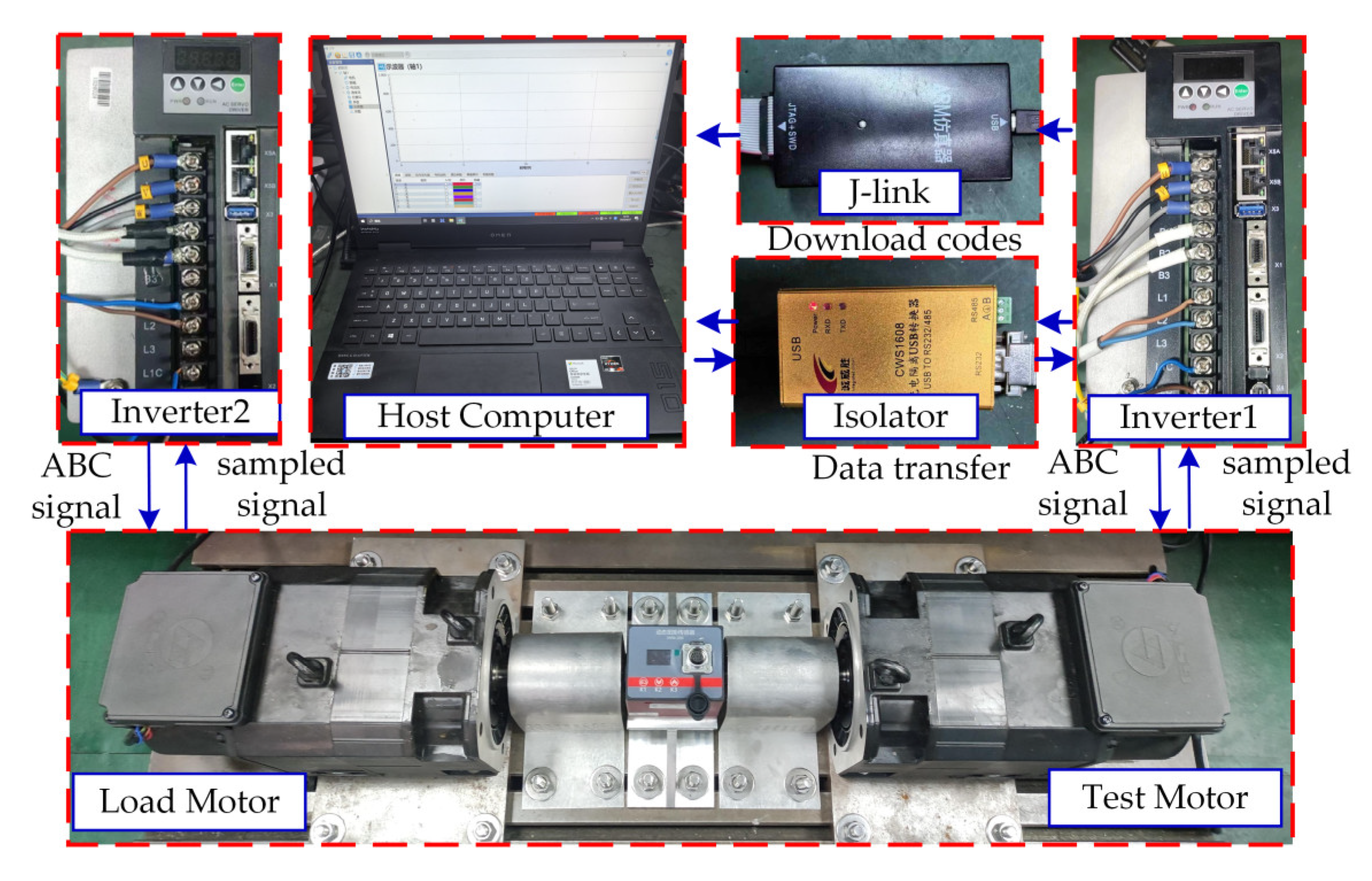
In order to verify the effectiveness of the SCFO proposed in this article, experiments were conducted on the experimental platform shown in Figure 5. This platform consists of two identical induction motors, two AC servo drives, a host computer, etc. The two induction motors and the torque sensor are coupled together. The motor on the right side of the platform is used to test the proposed algorithm, while the other motor operates in torque mode to supply load torque. The two induction motors and the torque sensor are mechanically connected through couplings, with the motor on the right side of the platform designated for testing the proposed algorithm, while the other motor operates in torque mode to provide load torque. The nominal parameters of the test motor are listed in Table 2. An incremental encoder with 5000 pulses per revolution is installed on each induction motor. Two AC servo drives based on STM32F103 are employed to control the motors separately. The phase current measured by sampling resistance is used for current control. The stator voltage is not directly monitored; instead, the flux observer utilizes the reference voltage derived from the current controller. The method from [28] is applied to compensate for the inverter nonlinearity. Both the switching frequency and the sampling frequency are set to 10 kHz. A host computer is utilized for data observation and code programming. In the experiments, the PLL is used to estimate the position and speed. The block diagram of the sensorless-driven induction motor system using the proposed scheme is shown in Figure 6. In the experiment, the gain of the proposed method and the conventional method are both set to 2. The integral gain of the stator resistance estimator is set to 1. Five independent repeated experiments were conducted, and the results obtained are very similar. The position obtained by the encoder is used solely for comparison in experiments.
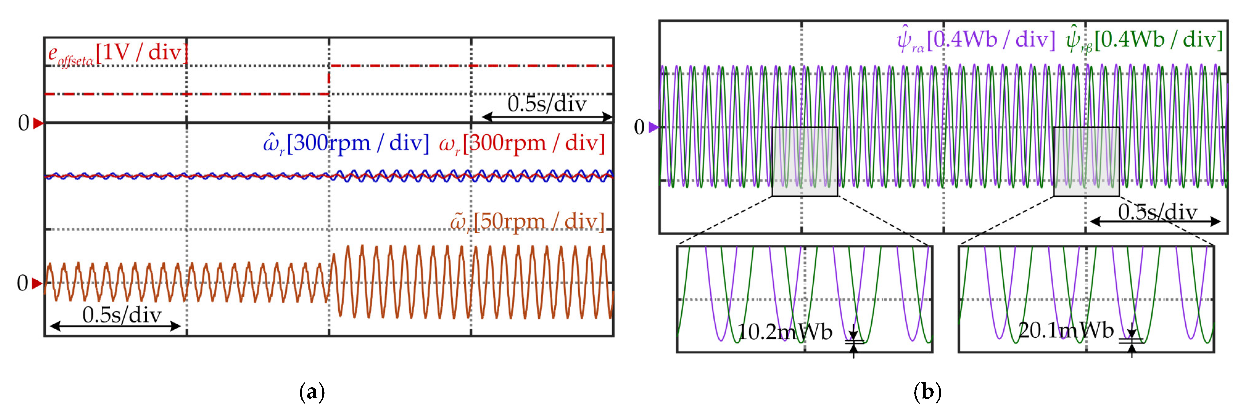
Figure 7 and Figure 8 show the experimental results of the conventional CFO and SCFO, respectively, under DC disturbances at 600 r/min and no load. As shown in Figure 7a,b, it is observed that there exists an apparent DC offset in the estimated rotor flux, and the estimated speed has fluctuations with a frequency of ωf. When the DC disturbance is injected into the α-phase changes from 1 V to 2 V, the speed estimation error increases. The difference between the DC components of the α-phase rotor flux and the β-phase rotor flux increased from 10.2 mWb to 20.1 mWb. From Figure 8, it can be seen that the proposed SCFO maintains excellent speed estimation performance under DC disturbances. When a DC disturbance is injected, the speed estimation error undergoes a slight fluctuation and then rapidly converges. This transient process involves estimating the DC component in BEMF. Once the estimation of the DC offset is completed, there is minimal change in both the speed estimation error and the estimated flux compared to the state before the injection of the DC disturbance. The experiments indicate that the studied observer can identify and suppress DC disturbance rapidly.
In order to validate the suppression ability of the proposed method for DC offset within different speed domains, the experimental results of the two flux observers under speed variations are presented in Figure 9 and Figure 10, respectively. It can be observed from Figure 9 that at low speeds, the DC offset in the flux estimation and the fluctuation of the speed estimation error are relatively large in conventional CFO. With the increase in rotor speed, the DC offset in flux estimation and the fluctuations of the speed estimation error decrease, but there still exists a speed estimation error with fluctuations at a frequency of ωf. In contrast, the speed estimation error of the proposed method is significantly smaller than that of the comparative method. As shown in Figure 10, the proposed method demonstrates excellent dynamic performance throughout the entire speed-up process.
The experimental results of the two flux observers under rated load at 400 rpm are shown in Figure 11 and Figure 12, respectively. From Figure 11a,b, it can be observed that when the load torque suddenly changes from 0 to 1 p.u., the speed estimation errors for the CFO methods increase. Conversely, the proposed method quickly estimates the DC component in the BEMF following an abrupt load change, resulting in smaller speed estimation errors compared to the conventional methods. The experiments demonstrated that the proposed method effectively achieves good DC offset elimination performance under rated load torque. Figure 13 presents the experimental results of the proposed method under rated load, with the speed ranging from 200 rpm to −200 rpm. From Figure 13, it can be observed that the speed estimation and flux estimation remain stable in the vicinity of 0 Hz frequency.
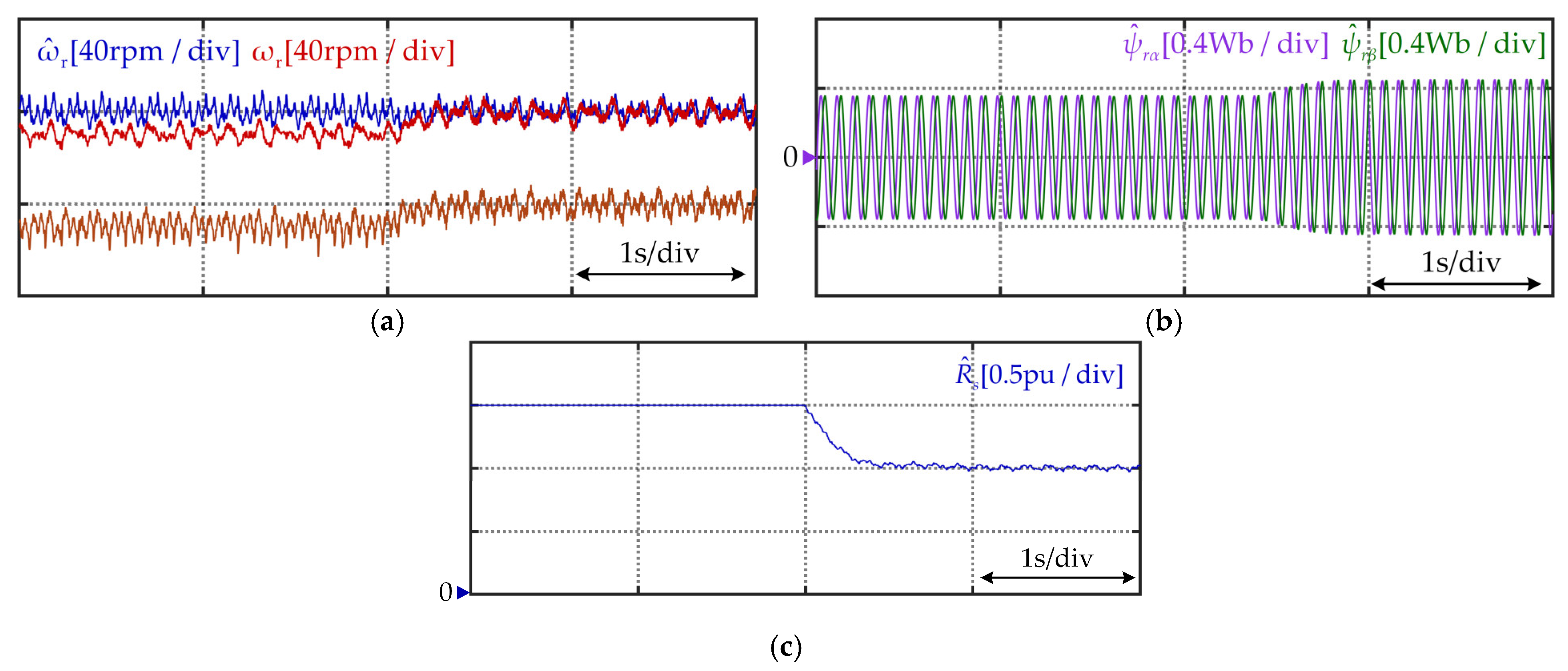
The experiment verified that the proposed SCFO has good dynamic performance at low frequencies. At 300 rpm and rated load, the experimental results for different initial stator resistance values are shown in Figure 14 and Figure 15, respectively. It can be observed from the figures that whether the initial stator resistance is 0.5 p.u. or 1.5 p.u., after enabling the stator resistance estimator, the stator resistance estimate quickly converges to the true stator resistance value. Once the stator resistance converges, the speed estimation error also converges simultaneously due to the convergence of the flux estimation.

6. Conclusions

In this article, A novel SCFO is proposed for sensorless induction motor drives. This flux observer effectively estimates the DC offset of the BEMF based on the orthogonality between the rotor flux and the BEMF, and it eliminates the DC offset in the flux estimation through feedforward compensation. The bandpass characteristic of the flux observer facilitates the elimination of the DC offset while maintaining consistency between the fundamental component of the flux estimation and that of the pure integrator. Furthermore, an improved stator resistance adaptive law based on the rotating reference frame is proposed. Finally, Comprehensive experimental results demonstrate that, compared to conventional methods, the proposed observer effectively eliminates the DC offset in flux estimation under both steady-state and dynamic conditions, thereby improving the accuracy of speed estimation.

Author Contributions

Conceptualization, K.Z. and B.S.; methodology, K.Z. and X.T.; software, X.Z.; validation, K.Z. and X.Z.; formal analysis, K.Z.; investigation, X.T.; resources, B.S.; data curation, X.Z.; writing—original draft preparation, K.Z.; writing—review and editing, X.Z.; visualization, K.Z.; supervision, B.S. and X.T.; project administration, X.Z.; funding acquisition, B.S. and X.Z. All authors have read and agreed to the published version of the manuscript.

Funding

This research was funded by the National Key R&D Program of China under Grant 2023YFB4704000 and the National Science and Technology Major Project under Grant 2024ZD0712101.

Data Availability Statement

The contributions presented in this study are included in the article; further inquiries can be directed to the corresponding author.

Conflicts of Interest

The authors declare no conflicts of interest.

Appendix A

Algorithm: SCFO
Input: Back-EMF   e α ( i + 1 ) , e β ( i + 1 ) ;   gain   k ;   sampling   time   T s ;   stator   frequency   ω ^ f .
Output: Rotor   flux   estimation   ψ S C F O α ( i + 1 )   , ψ S C F O β ( i + 1 ) .
1: e r α , 1 ( i + 1 ) e r α ( i + 1 ) - e ^ o f f s e t α ( i ) //Calculate back-EMF after DC offset compensation.
2: e r β , 1 ( i + 1 ) e r β ( i + 1 ) - e ^ o f f s e t β ( i )
3: e r r α ( i + 1 ) ψ SCFO , α ( i ) ω ^ f - e r β , 1 ( i + 1 ) sign ( ω ^ f )
4: e r r β ( i + 1 ) ψ SCFO β ( i ) ω ^ f + e r α , 1 ( i + 1 ) sign ( ω ^ f ) //Calculate quadrature error.
5: e ^ o f f s e t α ( i + 1 )   e ^ o f f s e t α ( i ) + T s k e r r α ( i + 1 ) //update offset estimation for next iteration
6: e ^ o f f s e t β ( i + 1 )   e ^ o f f s e t β ( i ) + T s k e r r β ( i + 1 )
7: ψ S C F O α ( i + 1 )   ψ S C F O α ( i ) + T s ( e α , 1 ( i + 1 ) k e r r α ( i + 1 ) ) //Calculate rotor flux estimation.
8: ψ S C F O β ( i + 1 )   ψ S C F O β ( i ) + T s ( e β , 1 ( i + 1 ) k e r r β ( i + 1 ) )
9: Return   ψ S C F O α ( i + 1 )   , ψ S C F O β ( i + 1 )  

References

  1. Chen, J.; Yuan, X.; Blaabjerg, F.; Lee, C.H.T. Overview of Fundamental Frequency Sensorless Algorithms for AC Motors: A Unified Perspective. IEEE J. Emerg. Sel. Top. Power Electron. 2023, 11, 915–931. [Google Scholar] [CrossRef]
  2. Reddy, C.U.; Prabhakar, K.K.; Singh, A.K.; Kumar, P. Speed Estimation Technique Using Modified Stator Current Error-Based MRAS for Direct Torque Controlled Induction Motor Drives. IEEE J. Emerg. Sel. Top. Power Electron. 2020, 8, 1223–1235. [Google Scholar] [CrossRef]
  3. Bıçak, A.; Gelen, A. Modified Super-Twisting Algorithm Based Model Reference Adaptive Observer for Sensorless Control of the Interior Permanent-Magnet Synchronous Motor in Electric Vehicles. Machines 2023, 11, 871. [Google Scholar] [CrossRef]
  4. Delorme, L.; Ayala, M.; Gonzalez, O.; Rodas, J.; Gregor, R.; Hernandez, J.C. SpeedSensorless Control for a Six-Phase Induction Machine Based on a Sliding Mode Observer. Machines 2025, 13, 639. [Google Scholar] [CrossRef]
  5. Tir, Z.T.; Kowalska, O.; Ahmed, H.; Houari, A. Adaptive High Gain Observer Based MRAS for Sensorless Induction Motor Drives. IEEE Trans. Ind. Electron. 2024, 71, 271–281. [Google Scholar] [CrossRef]
  6. Wang, H.; Yang, Y.; Ge, X.; Zuo, Y.; Yue, Y.; Li, S. PLL- and FLL-Based Speed Estimation Schemes for Speed-Sensorless Control of Induction Motor Drives: Review and New Attempts. IEEE Trans. Power Electron. 2022, 37, 3334–3356. [Google Scholar] [CrossRef]
  7. Wang, G.; Li, Z.; Zhang, G.; Yu, Y.; Xu, D. Quadrature PLL-Based High-Order Sliding-Mode Observer for IPMSM Sensorless Control with Online MTPA Control Strategy. IEEE Trans. Energy Convers. 2013, 28, 214–224. [Google Scholar] [CrossRef]
  8. Jiang, F.; Sun, S.; Liu, A.; Xu, Y.; Li, Z.; Liu, X.; Yang, K. Robustness Improvement of Model-Based Sensorless SPMSM Drivers Based on an Adaptive Extended State Observer and an Enhanced Quadrature PLL. IEEE Trans. Power Electron. 2021, 36, 4802–4814. [Google Scholar] [CrossRef]
  9. Lascu, C.; Boldea, I.; Blaabjerg, F. A modified direct torque control for induction motor sensorless drive. IEEE Trans. Ind. Appl. 2000, 36, 122–130. [Google Scholar] [CrossRef]
  10. Junggi, L.; Jinseok, H.; Kwanghee, N.; Ortega, R.; Praly, L.; Astolfi, A. Sensorless Control of Surface-Mount Permanent-Magnet Synchronous Motors Based on a Nonlinear Observer. IEEE Trans. Power Electron. 2010, 25, 290–297. [Google Scholar] [CrossRef]
  11. Holtz, J.; Juntao, Q. Drift- and parameter-compensated flux estimator for persistent zero-stator-frequency operation of sensorless-controlled induction motors. IEEE Trans. Ind. Appl. 2003, 39, 1052–1060. [Google Scholar] [CrossRef]
  12. Jo, G.-J.; Choi, J.-W. Rotor Flux Estimator Design with Offset Extractor for Sensorless-Driven Induction Motors. IEEE Trans. Power Electron. 2022, 37, 4497–4510. [Google Scholar] [CrossRef]
  13. Comanescu, M.; Xu, L. An improved flux observer based on PLL frequency estimator for sensorless vector control of induction motors. IEEE Trans. Ind. Electron. 2006, 53, 50–56. [Google Scholar] [CrossRef]
  14. Zhao, R.; Xin, Z.; Loh, P.C.; Blaabjerg, F. A Novel Flux Estimator Based on Multiple Second-Order Generalized Integrators and Frequency-Locked Loop for Induction Motor Drives. IEEE Trans. Power Electron. 2017, 32, 6286–6296. [Google Scholar] [CrossRef]
  15. Xu, W.; Jiang, Y.; Mu, C.; Blaabjerg, F. Improved Nonlinear Flux Observer-Based Second-Order SOIFO for PMSM Sensorless Control. IEEE Trans. Power Electron. 2019, 34, 565–579. [Google Scholar] [CrossRef]
  16. Jiang, Y.; Xu, W.; Mu, C.; Zhu, J.; Dian, R. An Improved Third-Order Generalized Integral Flux Observer for Sensorless Drive of PMSMs. IEEE Trans. Ind. Electron. 2019, 66, 9149–9160. [Google Scholar] [CrossRef]
  17. Zhang, Y.; Yin, Z.; Gao, F.; Liu, J. Research on Anti-DC Bias and High-Order Harmonics of a Fifth-Order Flux Observer for IPMSM Sensorless Drive. IEEE Trans. Ind. Electron. 2022, 69, 3393–3406. [Google Scholar] [CrossRef]
  18. He, W.; Wu, X.; Chen, J. Optimization Design of PMSM Sensorless Control Using Generalized Integrator. IEEE Trans. Ind. Electron. 2023, 71, 8625–8634. [Google Scholar] [CrossRef]
  19. Hinkkanen, M.; Luomi, J. Modified integrator for voltage model flux estimation of induction motors. IEEE Trans. Ind. Electron. 2003, 50, 818–820. [Google Scholar] [CrossRef]
  20. Stojic, D.; Milinkovic, M.; Veinovic, S.; Klasnic, I. Improved Stator Flux Estimator for Speed Sensorless Induction Motor Drives. IEEE Trans. Power Electron. 2015, 30, 2363–2371. [Google Scholar] [CrossRef]
  21. Vasic, V.; Vukosavic, S.N.; Levi, E. A stator resistance estimation scheme for speed sensorless rotor flux oriented induction motor drives. IEEE Trans. Energy Convers. 2003, 18, 476–483. [Google Scholar] [CrossRef]
  22. Chen, J.; Huang, J. Stable Simultaneous Stator and Rotor Resistances Identification for Speed Sensorless IM Drives: Review and New Results. IEEE Trans. Power Electron. 2018, 33, 8695–8709. [Google Scholar] [CrossRef]
  23. Luo, C.; Wang, B.; Yu, Y.; Chen, C.; Huo, Z.; Xu, D. Decoupled Stator Resistance Estimation for Speed-Sensorless Induction Motor Drives Considering Speed and Load Torque Variations. IEEE J. Emerg. Sel. Top. Power Electron. 2020, 8, 1193–1207. [Google Scholar] [CrossRef]
  24. Zaky, M.S.; Khater, M.M.; Shokralla, S.S.; Yasin, H.A. Wide-Speed-Range Estimation with Online Parameter Identification Schemes of Sensorless Induction Motor Drives. IEEE Trans. Ind. Electron. 2009, 56, 1699–1707. [Google Scholar] [CrossRef]
  25. Zaky, M.S.; Metwaly, M.K. Sensorless Torque/Speed Control of Induction Motor Drives at Zero and Low Frequencies with Stator and Rotor Resistance Estimations. IEEE J. Emerg. Sel. Top. Power Electron. 2016, 4, 1416–1429. [Google Scholar] [CrossRef]
  26. Zhao, L.; Huang, J.; Liu, H.; Li, B.; Kong, W. Second-Order Sliding-Mode Observer with Online Parameter Identification for Sensorless Induction Motor Drives. IEEE Trans. Ind. Electron. 2014, 61, 5280–5289. [Google Scholar] [CrossRef]
  27. Serra, F.M.; Dòria-Cerezo, A.; Bodson, M. A Multiple-Reference Complex-Based Controller for Power Converters. IEEE Trans. Power Electron. 2021, 36, 14466–14477. [Google Scholar] [CrossRef]
  28. Pellegrino, G.; Guglielmi, P.; Armando, E.; Bojoi, R.I. Self-Commissioning Algorithm for Inverter Nonlinearity Compensation in Sensorless Induction Motor Drives. IEEE Trans. Ind. Appl. 2010, 46, 1416–1424. [Google Scholar] [CrossRef]
Figure 1. Block diagram of the proposed SCFO.
Machines 13 00845 g001
Figure 2. Bode diagrams of SCFO, CFO, and the pure integrator.
Machines 13 00845 g002
Figure 3. Discrete Implementation of the proposed SCFO.
Machines 13 00845 g003
Figure 4. Block diagram of the stator resistance estimator.
Machines 13 00845 g004
Figure 5. Photograph of experimental equipment.
Machines 13 00845 g005
Figure 6. Block diagram of sensorless-driven induction motor system.
Machines 13 00845 g006
Figure 7. Experimental results of CFO under DC disturbance at 600 rpm without load. (a) Speed estimation and speed estimation error. (b) Rotor flux estimation.
Machines 13 00845 g007
Figure 8. Experimental results of SCFO under DC disturbance at 600 rpm without load. (a) Speed estimation and speed estimation error. (b) Rotor flux estimation. (c) Offset estimation.
Machines 13 00845 g008
Figure 9. Experimental results of CFO with speed varying from 200 rpm to 1000 rpm under 2 V DC disturbance. (a) Speed estimation and speed estimation error. (b) Rotor flux estimation.
Machines 13 00845 g009
Figure 10. Experimental results of SCFO with speed varying from 200 rpm to 1000 rpm under 2 V DC disturbance. (a) Speed estimation and speed estimation error. (b) Rotor flux estimation.
Machines 13 00845 g010
Figure 11. Experimental results of conventional CFO under 2 V DC disturbance with rated load at 400 rpm. (a) Speed estimation and speed estimation error. (b) Rotor flux estimation.
Machines 13 00845 g011
Figure 12. Experimental results of the proposed SCFO under 2 V DC disturbance with rated load at 400 rpm. (a) Speed estimation and speed estimation error. (b) Rotor flux estimation.
Machines 13 00845 g012
Figure 13. Experimental results of the proposed SCFO under rated load at speed reversals of ±200 rpm. (a) Speed estimation and speed estimation error. (b) Rotor flux estimation.
Machines 13 00845 g013
Figure 14. Experimental results of the proposed stator resistance estimator at 300 rpm with rated load (initial value: 0.5 p.u.). (a) Speed estimation and speed estimation error. (b) Rotor flux estimation. (c) Stator resistance estimation.
Machines 13 00845 g014
Figure 15. Experimental results of the proposed stator resistance estimator at 300 rpm with rated load (initial value: 1.5 p.u.). (a) Speed estimation and speed estimation error. (b) Rotor flux estimation. (c) Stator resistance estimation.
Machines 13 00845 g015
Table 1. Comparison of Computational complexity.
Flux ObserverOrderAddition
Operation
Multiplication
Operation
Offset
Suppression
CFO168medium
SOGI2812medium
TOGI31216Good
SCFO21012Good
Table 2. Parameters of the Tested Induction Motor.
ParameterValueParameterValue
rated speed1500 rpmmagnetizing inductance91 mH
rated voltage220 Vstator leakage inductance10 mH
rated current6.3 Astator resistance1.21 Ω
pole pairs2rotor resistance0.74 Ω
Disclaimer/Publisher’s Note: The statements, opinions and data contained in all publications are solely those of the individual author(s) and contributor(s) and not of MDPI and/or the editor(s). MDPI and/or the editor(s) disclaim responsibility for any injury to people or property resulting from any ideas, methods, instructions or products referred to in the content.