1. Introduction
Induction motors have become the backbone of numerous industrial applications due to their simple construction, high reliability, and low maintenance cost. However, mechanical sensors to measure speed and torque increase system complexity and cost in high-precision control applications such as industrial robotics and high-performance servomechanisms. Sensorless control emerges as an attractive solution to eliminate these devices, reducing maintenance, requirements, and vulnerability to sensor failures; nevertheless, it introduces the challenge of accurately estimating critical variables (speed, rotor flux, and torque), especially in the low-speed region, where current signals have small values and noise is predominant [
1,
2].
Recent reviews highlight the scope of modern control strategies for induction motors, from scalar and flux-oriented control to direct torque control, and their evolution through intelligent and robust algorithms [
3]. Advanced approaches such as backstepping combined with high-order sliding-mode control have demonstrated improved robustness and dynamic performance in sensorless applications [
4], while adaptive full-order observers and interconnected MRAS schemes have improved low-speed estimation accuracy and multiparameter identification [
5,
6]. MRAS-type estimators, extensively reviewed in [
7], can guarantee stability across the entire speed–torque range [
8] but remain sensitive to motor parameters, motivating the use of auxiliary estimators [
9]. Other proposals include stator-current-based observers with rotor-flux correction and fuzzy-logic adaptation [
10], neural-MRAS schemes for improved high-speed accuracy and ultra-low-speed tracking [
11], and sensorless vector control for induction generators in wind systems with high-precision speed estimation [
12].
Sliding-mode control (SMC) offers intrinsic robustness to parameter variations and disturbances, achieving exact decoupling of flux and torque loops once sliding motion is established [
13,
14]. Hybrid SMC–fuzzy logic and Lyapunov-based adaptations improve transient dynamics [
15], while second-order algorithms such as the twisting method reduce chattering without sacrificing robustness [
16]. Deadbeat regulators outperform proportional-integral controllers in response speed and overshoot reduction [
17], while the adaptive neuro-fuzzy inference system and MRAS schemes deliver higher efficiency and shorter settling times [
18]. Robust differentiators [
19,
20] provide strong noise rejection and finite-time convergence, making them suitable for noisy sensorless applications. Despite these advances, key challenges remain, such as ensuring asymptotic stability of observers under variable-speed and regenerative-mode conditions, achieving exact speed control in the presence of parametric uncertainties, field weakening, zero-speed operation, and low switching (minimal chattering). As previously described, sensorless speed control remains an open research area intended to achieve high dynamic performance, accurate estimation, and robustness against model parameter uncertainties.
The main contribution of this work is the synthesis of a sensorless rotor speed control system for induction motors, designed to operate with minimal parameter dependency. The proposed system integrates three robust components, (a) a rotor speed controller, (b) a rotor speed and flux linkages observer, and (c) a differentiator, each employing sliding-mode techniques in their inputs to enhance robustness. In the rotor speed controller, a novel rotor flux reference function is introduced to adjust the motor magnetization level of the induction motor according to the stator currents, which in turn depend on the load torque. This approach, to the best of our knowledge, has not been reported in the literature. Additionally, a sliding variable is designed using the linearization state feedback technique. By applying the super-twisting control law to this sliding variable, its value is driven to zero in finite time, ensuring smooth convergence of the controlled variables. In the robust observer, two complementary sliding-mode inputs are combined, another novelty of this work. A first-order discontinuous input forces the movement of a nonlinear sliding function to zero in finite time, achieving convergence of the estimated rotor flux linkages. Simultaneously, a super-twisting quasi-continuous input drives another nonlinear sliding function to zero in finite time, ensuring accurate rotor speed estimation. Finally, the robust differentiator employs the super-twisting algorithm to compute the time derivative of the tracking error variable in the presence of noise, eliminating the need for direct load-torque measurement. The proposed methodology guarantees asymptotic stability under time-varying speed, load, and parameter uncertainties. Experimental validation confirms its high efficiency, precise estimation capability, and strong robustness.
This article is organized as follows:
Section 2 introduces the squirrel-cage induction motor space–state model and the model’s inductance parameter definitions; in
Section 3 the synthesis of the speed controller applied to induction motor is developed;
Section 4 shows the development of the speed and rotor flux observer based on first-order and supertwisting sliding modes as inputs to the system, aiming to achieve convergence in the observed variables. In
Section 5 a robust differentiator is introduced from recent literature. The differentiator has the ability to deal with noisy signals.
Section 6 presents experimental results to measure the performance of the open-loop speed and rotor flux observer and also the closed-loop sensorless speed controller of the induction motor.
3. Induction Motor Model
The induction motor is a robust machine of simple construction, with acceptable speed regulation. The motor is magnetized by both the stator winding and the rotor winding by electromagnetic induction. The squirrel-cage induction motor model at the
frame takes the following form:
where
is the angular speed, while the rotor winding flux linkages and stator winding current and voltage vectors, respectively, are described by
where term
is the load torque (a mechanical external input), which is considered as a disturbance for the induction motor model, and the parameter constants are
with
P being the pole pairs,
is the coefficient of friction of the support points in the shaft train,
is the moment of inertia of the shaft train,
and
are the rotor and stator resistances, respectively, and finally,
,
, and
are inductance parameters defined in the process of establishing the induction motor model according to the theory of magnetically coupled circuits. The definition of these inductances is presented in the following subsection.
3.1. Definition of Induction Motor Model Inductances
The physical interpretation of the inductance parameters in the state-space model of the induction motor is crucial to avoid numerical errors when there is dependence on these parameters during the design of a state observer or the synthesis of the control system. The model’s inductances (
1) have the following definitions
where
is the stator self-inductance per-phase,
is the stator mutual inductance between two phases,
is the rotor self-inductance per-phase,
is the rotor mutual-inductance between two phases, and
is the maximum value of the mutual inductance between stator and rotor winding.
The relations between the inductances of the equivalent circuit in
T and the inductances of the induction motor model (
2)–(
4) are defined in [
21], as follows:
where
a is the ratio of turns between the stator and rotor winding per-phase; for the squirrel-cage induction motor this parameter can be considered as
;
is the leakage inductance of the stator,
is the magnetizing inductance, and
is the leakage inductance of the rotor referred to the stator side.
Accordingly, substituting (
5)–(
7) in (
2)–(
4), and considering the mutual inductance between any two stator phases as
and any two rotor phases as
[
22], the following relations are obtained [
21]:
Equations (
8)–(
10) define the inductance parameters used in the squirrel-cage induction motor model (
1) in terms of the standard inductance parameters obtained from the no-load and blocked-rotor tests of the induction motor.
3.2. Adjustment of the Leakage Reactances and Stator Resistance
Once the reactance and resistance parameters of the induction motor have been determined through no-load and locked-rotor tests, it is suggested to adjust the values of the leakage reactances according to the type of squirrel-cage rotor and the rotor resistance to consider the skin effect when conducting alternating currents. The process consists of comparing the complex power, measured in the laboratory, of the motor under nominal load conditions and the complex power calculated through the equivalent circuit in T, under the same operating conditions. To obtain approximate values for power consumption in the analytical part with respect to the experimental part, a parametric analysis is performed on the stator resistance and on the percentage of each leakage reactance with respect to the reactance of the locked rotor test. The analysis stops when the complex power values are very similar.
4. Speed Control System Design for the Squirrel-Cage Induction Motor
Based on the motor model, the state-feedback speed control scheme can be synthesized; nonetheless, an observer will be needed for estimating the load torque and the variables of speed and the rotor flux linkages, as given in
Section 5. As part of the control design, a state-feedback linearization mechanism is used to transform the motor model to the controllable canonical form via the definition of an error variable, which converts the problem of regulating the variables to a desired point into the stabilization of the error. The
induction motor model (
1) is a nonlinear system, which contains two electrical inputs to be determined to supply voltages to the stator winding,
and
. As a consequence, two output variables, in this case, the angular speed
and the squared modulus of rotor flux linkages
, can be controlled at a desired value.
For the state-feedback linearization, the following error vector is defined as
where
and
are the reference set points to be followed by the output variables, and
Based on (
11) a second error variable is defined as
and by employing the time derivative of (
11), which takes into account the motor model (
1), the following is obtained:
By calculating the dynamics of
, the induction motor model (
1) is replaced in (
15), yielding the following:
where
. From (
14) and (
16), the following canonical representation is obtained
The transformed system (
19) dynamically behaves as the motor model (
1), and for the synthesis of a robust controller, the following variable is designed:
where a diagonal matrix
is selected to define the convergence rate of the error variables. The dynamics of (
20) results in
Nonetheless, system (
21) has coupled the input
to the rotor flux linkages, as noted in (
16) and (
18). Thus, a decoupling, and in addition an order reduction, is achieved by proposing the following transformation:
whose dynamics becomes
with
Finally, the super-twisting control scheme is applied to the new decoupled system (
23), yielding the closed-loop system
where
and
are diagonal matrices whose entries have high enough values to force the motion of the sliding variables
(
22) and its time derivative
(
23) to zero. As a consequence, the sliding variable
in (
20) reaches the origin in finite time, and thus an asymptotic motion to zero is ensured for the error variables of the speed and the squared modulus of the rotor flux linkages.
The stability analysis for (
24) can be analyzed by presenting the system in the following scalar form:
Then, a new variable is defined to obtain a dynamical system, which is appropriate for the stability analysis [
20]:
where its time derivative results in
System (
27) can be expressed as the following perturbed system:
where
,
,
, and function
is bounded by the following restrictions:
The stability of system (
28) comes from using a candidate Lyapunov function as follows [
23]:
where
Deriving in time the function (31) along the trajectories of the system, it results in
Assuming that
in (
25) is an external disturbance bounded by
Involving (
32) in the term
of (
31) yields the following [
20]:
where
The matrix
must be positive definite, then
and
values must fulfill the following conditions:
and the time derivative of system (
33) is then negative definite, ensuring the asymptotic system stability. Inequalities (
34) provide a finite time attractively sliding-mode condition on the set
and
, and as a consequence, an asymptotic movement of the tracking error variable
is achieved.
5. Rotor Speed and Rotor Flux Linkages Observer Synthesis
The sensorless control scheme refers to implementing a speed motor control without the mechanical measurements, specifically the speed and the load torque; therefore, these variables need to be estimated. Additionally, the rotor flux linkages and stator currents are estimated through an observer, which converges based on the current estimation error. To this end, the rotor flux and speed observer synthesis are based on the electrical model of the induction motor (
1) in the
frame, as follows:
where
,
are the estimated rotor flux linkages and
,
are the estimated stator currents; parameter
C is an observer adjustment constant, where
.
The estimate of rotor flux leakages and stator currents in the
frame is made through the following first-order sliding-mode input:
where
is an observer gain, and the nonlinear sliding function
is defined as follows [
13]:
As demonstrated in [
13], the rotor flux observer convergence depends on the definition of the nonlinear function
given in (37) as an argument for the discontinuous input of the first-order sliding modes (36). The details of stability analysis can be revised in [
13]. Meanwhile, the estimate of the rotor speed
is made through quasi-continuous input using the super-twisting algorithm, as follows:
where
and
are the observer gains, while
is a nonlinear sliding function, which is defined as follows [
13]:
The observation convergence is achieved through the observation error of the stator currents in (
37) and (
39), as demonstrated in [
13].
7. Results
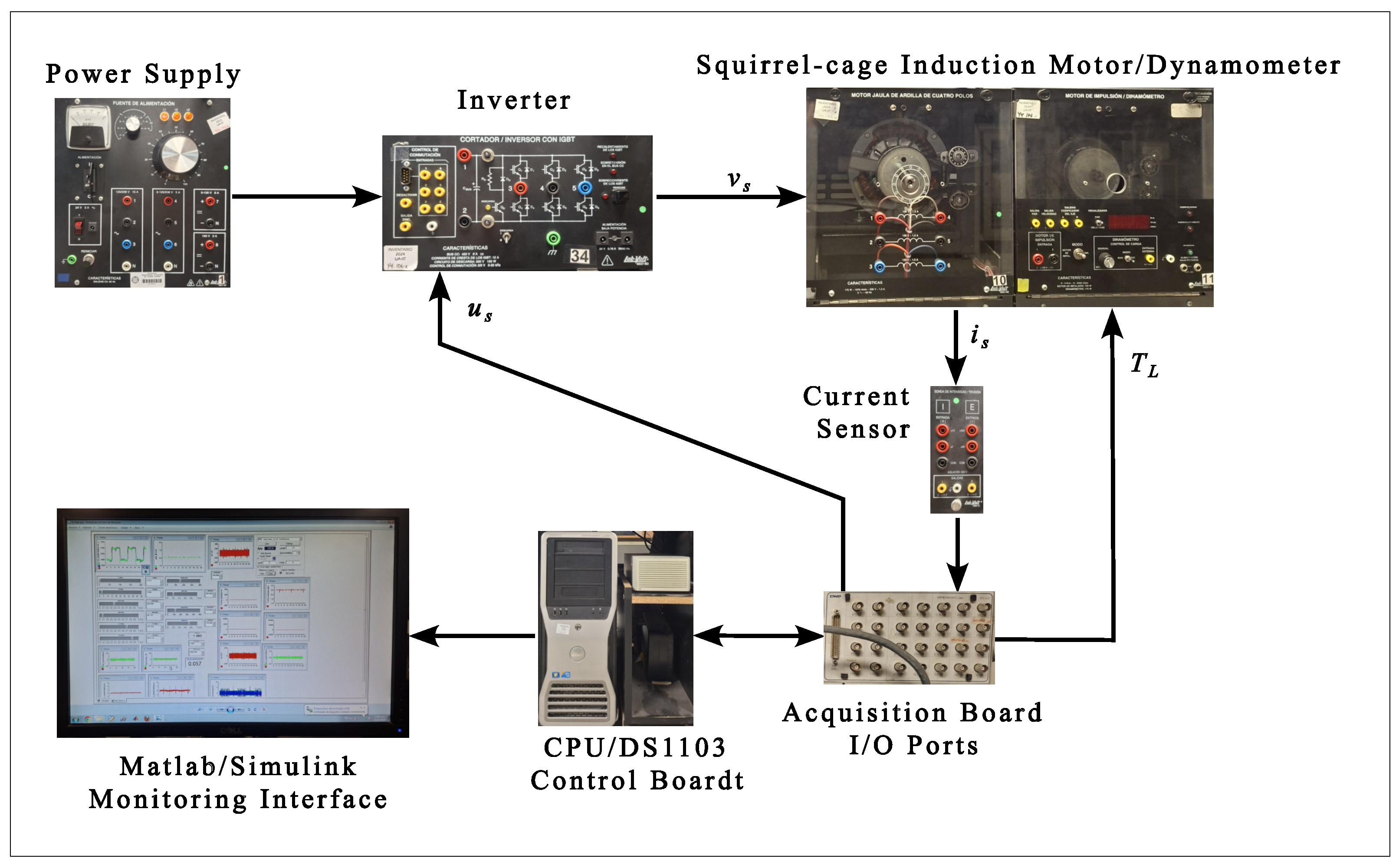
The real-time sensorless rotor speed controller runs on a dSPACE 1103 Control Board kit (Paderborn, Germany) interfaced with LabVolt academic equipment (Québec, QC, Canada), with algorithms implemented in MATLAB/Simulink, version 2011b. The results were obtained on a test bench comprising a 260 V DC bus from the power supply, which feeds a three-phase bridge-type inverter operating at a switching frequency of 4.68 kHz. The inverter supplies a controlled voltage
to a squirrel-cage induction motor mechanically coupled to a dynamometer via a toothed belt. The base program was configured in MATLAB/Simulink using a fixed-step solver with a 100 µs time step and was compiled for the dSPACE DS1103 control board. The rotor speed controller takes the stator current
as its only input and generates a control signal
as output, which is conditioned to activate the inverter. To generate the control signal, the system estimates both the rotor speed and the rotor flux linkage and calculates the argument of the control law by applying the linearization state feedback technique. Additionally, the system configures the load torque of the dynamometer and sends it through an analog output.
Figure 2 shows the schematic of the induction motor speed control system. The induction motor nameplate data are as follows: 175 W, 120 V, 1.5 A, and 1740 r.p.m. The parameters used in the experimental tests are presented in
Table 1, which includes both the motor parameters and the gains for tuning the controller and the gains to achieve observer convergence.
Two laboratory experiments were conducted to validate the proposed sensorless rotor speed control system. The first experiment assessed the observer’s capability to estimate rotor speed and rotor flux linkages under external disturbances such as sudden load-torque steps and supply-voltage fluctuations. The second experiment evaluated the closed-loop sensorless speed controller under external disturbances.
7.1. Rotor Speed Observer Performance
Using the robust observer (
35), both rotor speed and rotor flux linkages are simultaneously estimated.
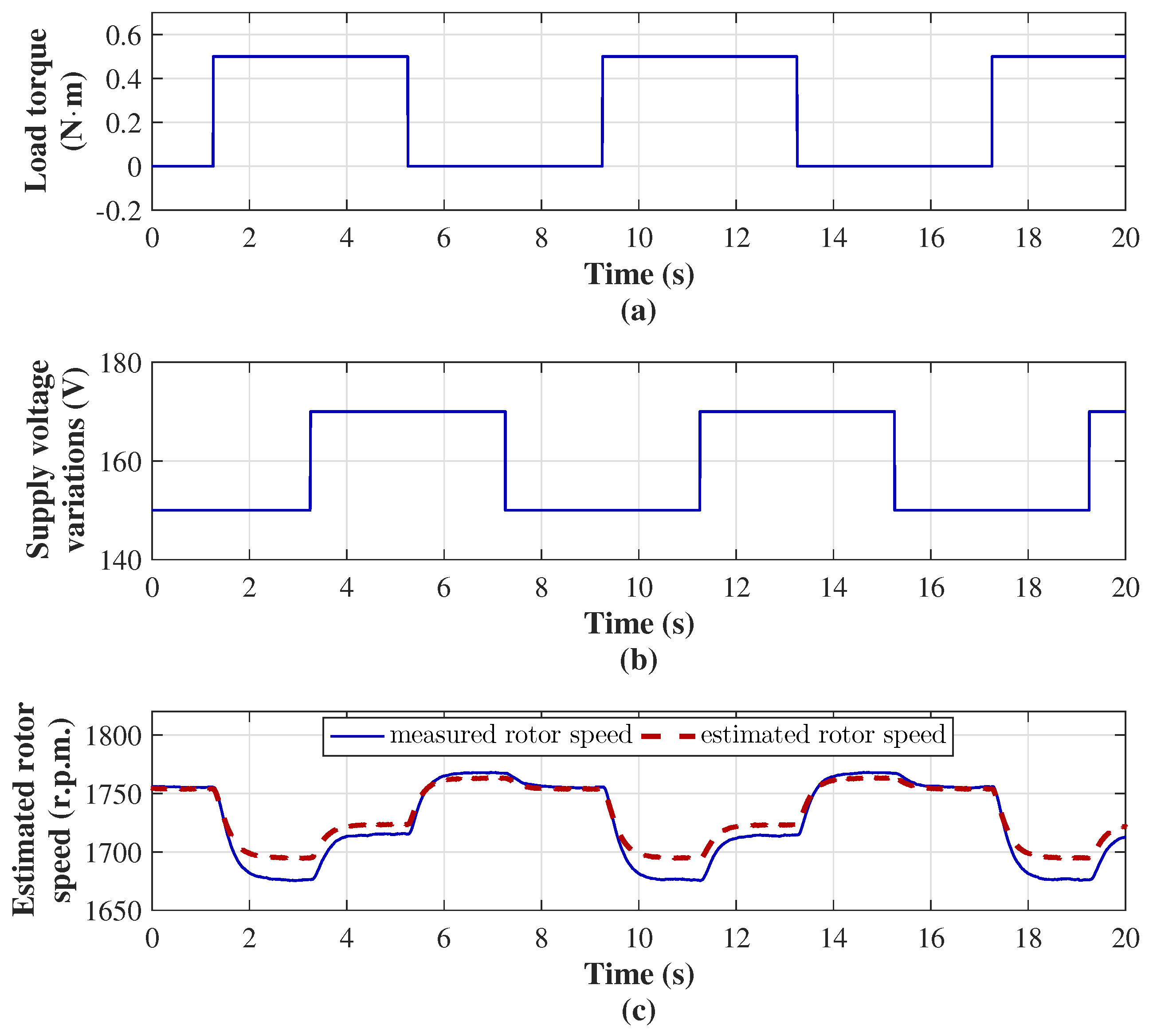
Figure 3 depicts the rotor speed estimation performance of the observer under external disturbances. A load-torque pulse train with a 0.5 N·m amplitude, 4 s pulse, and 8 s period was applied. Simultaneously, the supply voltage amplitude is varied from 150 to 170 V with a pulse train phase-shifted by 2 s with respect to the load-torque pulse train, see
Figure 3a,b. Rotor speed estimation remains highly accurate under varying external disturbances, as shown in
Figure 3c.
The observer’s performance in estimating the rotor flux linkages based on the observation of currents in the
reference frame is shown in
Figure 4. The estimated current closely follows the measured current on both the
and
axes, as illustrated in
Figure 4a and
Figure 4b, respectively. Thereby, the rotor flux linkages are estimates, with a maximum value of approximately 0.35 Wb-turn and are 90 degrees out of phase with each other.
7.2. Sensorless Rotor Speed Controller Performance
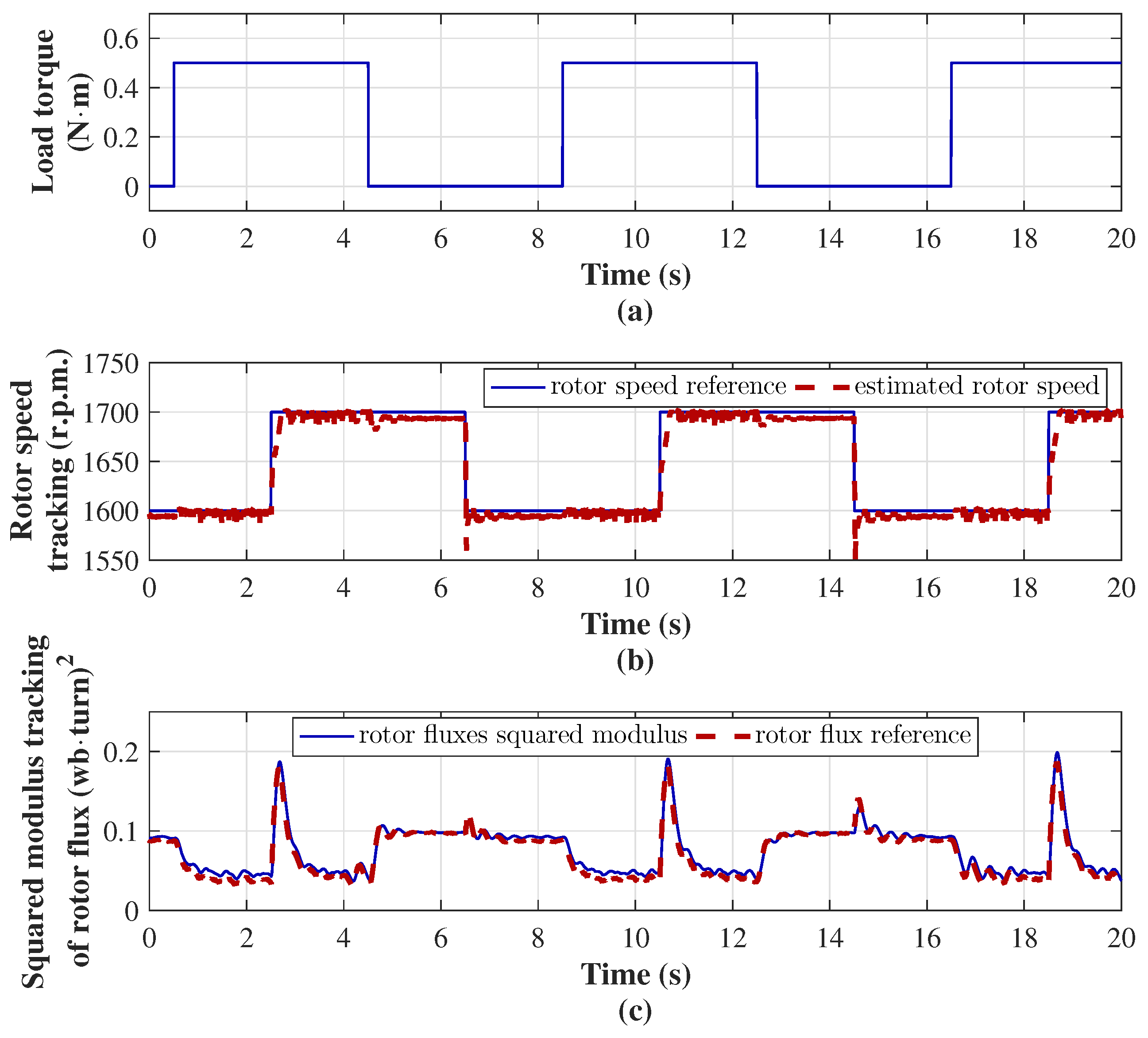
The control goal of the sensorless rotor speed controller consists of the tracking of the rotor speed and the squared modulus of the rotor flux linkages with their references in the presence of changes in load torque and reference speed, as is shown in
Figure 5. The load torque, as an external disturbance, is configured through a pulse train with an amplitude of 0.5 N·m, a pulse of 4 s, and a period of 8 s. Simultaneously, the speed reference varies with another pulse train phase-shifted by 2 s with respect to load-torque pulse. The speed reference oscillates between 1600 and 1700 r.p.m. every 0.8 s, and the control action forces the estimated rotor speed to closely track the reference, as shown in
Figure 5b. This demonstrates that the control system of the speed tracking remains accurate despite the presence of the load-torque pulse train (
Figure 5a) and sudden changes in the speed reference. Meanwhile, the squared modulus of the rotor flux linkages (
13) enables precise reference tracking (
12), even under simultaneous changes in load torque and speed reference, as shown in
Figure 5c. Rotor flux tracking varies due to changes in the rotor flux linkages reference as the current follows changes in the load torque.
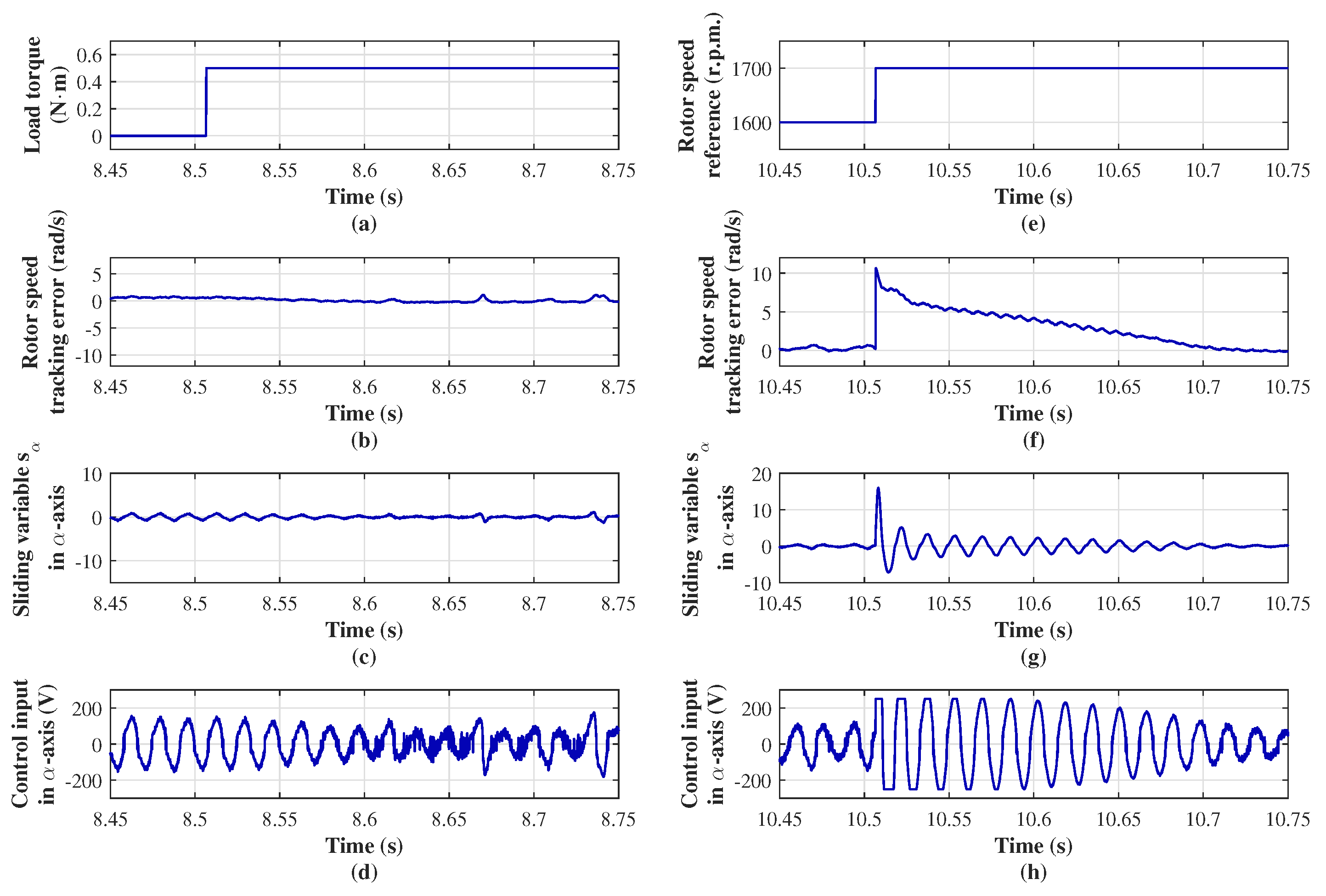
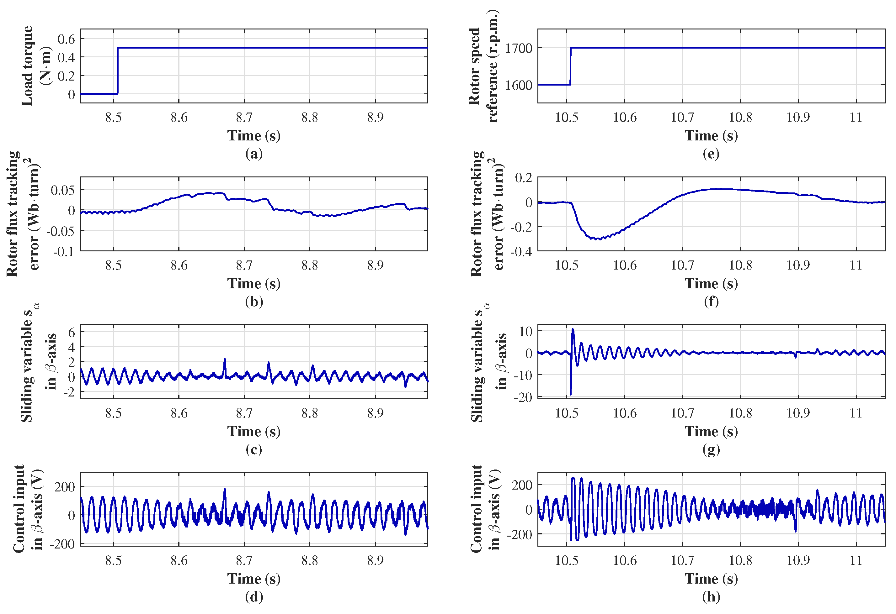
The performance of the control input in the
-axis under external disturbances is shown in
Figure 6.
Figure 6a–d show the response to the change in the input load torque, while
Figure 6e–h show the response to the change in the reference speed. A change in load torque from 0 to 0.5 N·m, applied as an external disturbance, has little effect on the control action
, as illustrated in
Figure 6a–d. When the speed reference changes from 1600 to 1700 r.p.m. at
s (
Figure 6e), the control action successfully drives the sliding variable (
22) to the origin in approximately 0.2 s (
Figure 6g). This ensures a smooth convergence of the speed tracking error variable (
20) to zero within the same time frame (
Figure 6f), fulfilling the goal of controlling the induction motor speed. The control input, interpreted as the voltage applied to the stator winding in the
-axis, is depicted in
Figure 6h. When the change in reference speed acts as an external disturbance,
saturates at 250 V. Since the supply source can only provide a maximum of 180 V, this limitation delays the system’s transient transient response.
The performance of the control input in the
-axis under external disturbances is presented in
Figure 7. In
Figure 7a–d, the load torque changes from 0 to 0.5 N·m (
Figure 7a). Following this torque increase, the control action
forces the sliding variable to the origin (
Figure 7c), leading to a smooth convergence of the flux tracking error to zero (
Figure 7b). Meanwhile,
Figure 7e–h show the response to reference speed change. When the speed reference changes from 1600 to 1700 r.p.m. as an external disturbance (
Figure 7e), the control input acts immediately to drive the sliding variable to zero within approximately at 0.4 s albeit with oscillatory behavior. Consequently, the tracking error of the flux squared modulus also converge smoothly to zero at 0.4 s. At the onset of the transient, the control input saturates at 250 V.
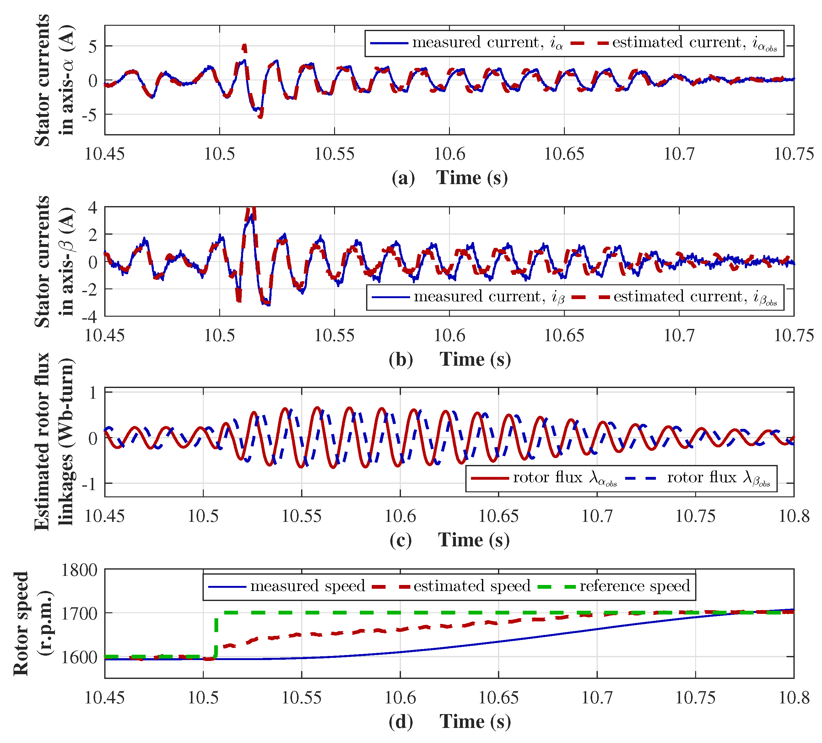
A robust observer, responsible for estimating rotor speed and flux linkages, is essential for the operation of the control system. Its performance under external perturbations, such as a change in the reference speed, is illustrated in
Figure 8. The estimation of the stator currents in the
axes is of high accuracy, see
Figure 8a,b, and allows a reliable estimation of both the rotor flux links and the rotor speed. When a disturbance occurs due to a sudden change in the reference speed from 1600 to 1700 r.p.m. at
s, oscillations appear in the estimated rotor flux links (
Figure 8c). Finally, the estimated rotor speed converges to the measured rotor speed in the time range of 0.26 s, see
Figure 8d.
8. Conclusions
In this work, a robust speed control system for the induction motor, which eliminates the need for mechanical sensors, is presented. Its performance is validated through experimental testing, demonstrating robust operation under varying load torques and reference speed changes. The proposed control system utilizes the sliding-mode super-twisting control law, which forces the sliding variable to move towards the origin in finite time, thereby asymptotically decaying the error variable to zero. With this, the rotor speed and the modulus of the rotor flux linkages reach their references. It is essential to highlight one of the contributions of this work, which consists of the reference function of the rotor flux module, which automatically adjusts with changes in stator currents, because of the motor operating conditions. Simultaneous estimation of rotor speed and rotor flux linkages is carried out using a robust observer based on sliding modes. A first-order sliding-mode input steers a nonlinear sliding function toward the origin. At the same time, a super-twisting sliding-mode input forces a second nonlinear sliding function towards zero. This is to achieve convergence of the estimated rotor speed and flux linkages. This combination represents a novel contribution by enabling finite-time convergence of both rotor speed and squared rotor flux magnitude while ensuring smooth transient behavior. These results confirm the effectiveness of the proposed control and observation strategy for induction motor drives. Finally, the results confirm its practical applicability beyond laboratory settings. By bridging robust nonlinear control theory and practical implementation in induction motor drives, this work advances the research line on finite-time sensorless control, providing a reproducible framework that other researchers and practitioners can adopt, refine, and extend.

