Article

High-Temperature Degradation of Throttling Performance in While-Drilling Jars Induced by Thermal Expansion and Fluid Rheology

National Key Laboratory of Oil and Gas Reservoir Geology and Exploitation, Southwest Petroleum University, Chengdu 610500, China
*
Author to whom correspondence should be addressed.
Machines 2025, 13(9), 824; https://doi.org/10.3390/machines13090824
Submission received: 16 July 2025 / Revised: 11 August 2025 / Accepted: 15 August 2025 / Published: 7 September 2025
(This article belongs to the Section Machine Design and Theory)

Abstract

During deep and ultra-deep well drilling operations, the throttling performance of the hydraulic-while-drilling jar is significantly affected by the combined influence of temperature-induced differential thermal expansion among components and changes in the rheological properties of hydraulic oil. These effects often lead to unstable jarring behavior or even complete failure to trigger jarring during stuck pipe events. Here, we propose a high-temperature degradation evaluation model for the throttling performance of the throttle valve in an HWD jar based on thermal expansion testing of individual components and high-temperature rheological experiments of hydraulic oil. By using the variation characteristics of the throttling passage geometry as a linkage, this model integrates the thermo-mechanical coupling of the valve body with flow field simulation. Numerical results reveal that fluid pressure decreases progressively along the flow path through the throttle valve, while flow velocity increases sharply at the channel entrance and exhibits mild fluctuations within the throttling region. Under fluid compression, the throttling areas of both the upper and lower valves expand to some extent, with their spatial distributions closely following the pressure gradient and decreasing gradually along the flow direction. Compared with ambient conditions, thermal expansion under elevated temperatures causes a more pronounced increase in throttling area. Additionally, as hydraulic oil viscosity decreases with increasing temperature, flow velocities and mass flow rates rise significantly, leading to a marked deterioration in the throttling performance of the drilling jar under high-temperature downhole conditions.

1. Introduction

As a critical component of the drilling system, the hydraulic-while-drilling (HWD) jar is deployed into the wellbore along with the drill string during drilling operations [1,2,3]. However, with increasing drilling depth, the throttling performance of the jar significantly deteriorates due to the gradually intensifying downhole temperature, frequently leading to operational issues such as failure to trigger jarring or insufficient jarring force, thereby substantially prolonging non-productive time [4,5]. In fact, due to differences in the thermophysical properties of the jar’s internal components, differential thermal expansion occurs under temperature gradients, causing geometrical changes in the throttling passage of the valve during drilling. When the drill string becomes stuck, the driller typically lifts the string to initiate the energy accumulation phase of the jar. During this phase, hydraulic fluid in the high-pressure chamber is driven by the pressure differential to flow through the throttling surface into the low-pressure chamber. Under such conditions, the throttling valve and its seat undergo further deformation due to the extrusion of the high-pressure fluid, resulting in additional changes in the geometry of the throttling surface. Therefore, when evaluating the throttling performance of the valve, it is essential to consider the dynamic variation of the throttling area under high-temperature and high-pressure conditions.
In order to study the throttling characteristics of different types of throttle valves, experts and scholars have conducted a lot of work. Y. K. Fu et al. [6] theoretically derived the valve core surface curve equations and first demonstrated a linear relationship between pressure differential and valve opening. This finding was later experimentally validated by G. R. Wang et al. [7] through controlled pressure drilling valve tests. Abdelrahman M. Awad et al. [8] found that temperature-induced variations in the rheological properties of drilling fluids significantly affect shear resistance during flow, which in turn influences the cuttings transport and settling velocity. Evgeniy Boyko [9] established a theoretical framework for non-Newtonian fluid flow in deformable pipes, confirming that the shear-thinning effect can significantly reduce flow resistance. Zhang et al. [10], using a multiphase CFD model, found a nonlinear relationship between pressure drop and valve opening. By analyzing flow characteristic curves, they optimized the valve core design to enable precise control of wellhead backpressure. Wang et al. [11] applied the Direct Simulation Monte Carlo (DSMC) method to investigate rarefied flow characteristics in micro-nozzles, revealing that increasing the needle valve’s relative opening encouraged the dominance of continuum flow in the microfluidic region. D. Singh et al. [12] developed a correlation between void fraction and flow coefficient to quantify local gas–liquid distribution in valves operating under severe conditions. Ivan Okhotnikov et al. [13] designed a high-flow rotary hydraulic valve and reduced flow forces through structural optimization of the valve core, achieving stable control at flow rates up to 150 L/min in a single-stage operation. Ye et al. [14] compared the effects of different valve core geometries in high-pressure hydrogen needle valves. Their results showed that an arc-cone core increased flow by 2% and reduced rotational speed by 15%, while a flat-cone core effectively suppressed turbulence and energy loss. Zhao et al. [15] proposed a novel trapezoidal throttling orifice structure that improved pressure differential by 18.6% compared with traditional rectangular geometries, with the optimal anti-erosion performance observed at a 20° taper angle. Zhu et al. [16] accurately predicted erosion-induced deformation of needle valves in gas–solid two-phase flow and confirmed their high sensitivity to pressure and fluid rheological properties. Wu and Zhao et al. [17,18] explored erosion mechanisms in gas–solid two-phase flows within needle valves. Their study indicated that the front end of the valve core was prone to eccentric wear and erosion under horizontal installation. Additionally, valve opening at 25% was associated with particle-induced clogging, while openings above 50% led to intensified valve chamber corrosion. Subsequently, Ali Kibar et al. [19] demonstrated through experimental and CFD comparisons that slotted-end valves achieved optimal throttling stability at openings below 40%, with peak flow control precision observed near 20% opening. To address the limited accuracy of hydraulic simulations under high-temperature and high-pressure (HTHP) conditions, Ye et al. [20] proposed an innovative non-parametric prediction method for fluid rheological properties. By inverting model parameters from rheological measurements, this method significantly improved simulation accuracy in HTHP environments. Hou et al. [21] developed a numerical model of internal flow and throttling characteristics in a multi-stage high-pressure pressure-reducing valve based on the RNG k-ε turbulence model. They found that a 180° relative angular configuration yielded the optimal pressure drop performance, and that a single-orifice structure effectively reduced turbulence. Chen et al. [22,23] designed a novel L-shaped multi-stage pressure-reducing valve and demonstrated that the rhombic perforated plate achieved the best comprehensive performance. They also observed that increasing both the orifice diameter and the sleeve diameter significantly enhanced aerodynamic characteristics. Furthermore, the adoption of multi-stage perforated plates was shown to evenly distribute pressure drop gradients and mitigate local flow instabilities. In the same year, they highlighted that the throttling process is jointly governed by the multi-orifice sleeve and valve core. Increasing the orifice diameter and pressure ratio was found to intensify turbulent energy dissipation, whereas raising the number of perforated stages effectively reduced energy loss.
Despite the extensive research conducted on the throttling performance and geometric optimization of throttle valves over the past decades, most studies have primarily focused on surface and wellhead applications, where thermal degradation is relatively insignificant. In contrast, under downhole high-temperature conditions, the throttling performance of hydraulic-while-drilling (HWD) jars can be significantly affected due to the combined influence of the thermophysical properties of internal components and the temperature-dependent rheological behavior of hydraulic oil. However, studies specifically addressing the high-temperature degradation of throttling performance in downhole HWD jars during jarring operations in deep and ultra-deep wells remain limited. In fact, due to the differences in the thermophysical properties of various components, the geometry of the throttling passage undergoes changes under high-temperature environments. To address this challenge, we propose an integrated evaluation model based on experimental data on the high-temperature rheological behavior and thermal expansion characteristics of hydraulic oil. In this model, the temperature-induced geometric deformation of the throttling passage is introduced as a coupling mechanism to integrate the thermo-mechanical deformation of the valve structure with flow field simulations. Throttling performance degradation is quantitatively assessed by comparing flow velocities and mass flow rates through the throttling passage under different temperature conditions.

2. The Throttling Principle of Drilling Jar

The evolution trend of the internal flow field of the drilling jar during up- and down-jarring operations is generally consistent, governed by the relative position between the outer cylinder sealing surface and the central valve seat. Therefore, we take the up-jarring operation as an example and extract the assembly states of key components along with the corresponding internal flow fields of the drilling jar at different time points, as illustrated in Figure 1.
At the initial stage (Moment A), the central valve has not yet contacted the metallic sealing surface of the cylinder sleeve, and the upper and lower hydraulic chambers of the drilling jar remain connected, the hydraulic fluid to flow freely within the jar. When a stuck pipe event occurs, the driller at the surface lifts the drill string, causing the jar mandrel to move upward under axial load. At this point, although the upper central valve begins to contact the metallic sealing surface and forms an initial seal, hydraulic fluid can still flow freely through the gap between the valve seat and the mandrel (Moment B).
As the lower central valve seat contacts and seals against the metallic sealing surface, the drilling jar gradually enters the energy-storing phase (Moment C). At this time, the hydraulic oil in the high-pressure chamber must flow through the needle-type throttling valve located inside the lower central valve and entering the lower chamber. With the mandrel continuing to move upward, the seal between the upper central valve and the metallic surface fails (Moment D). However, since the lower central valve seat remains sealed, the upper and lower chambers remain isolated, and the system continues in a closed pressure-holding state.
Once the lower section of the mandrel instantaneously passes through the sealing surface of the outer cylinder (Moment E), the upper and lower chambers of the jar are suddenly connected, and the throttling resistance drops to zero. At this instant, the mandrel is rapidly accelerated by the release of stored elastic energy in the drill string, generating a high-intensity jarring force.
Similar to the evolution trend of the flow field inside the drilling jar during the up-jarring operation, the flow passage during the down-jarring operation are mainly influenced by the relative position between the outer cylinder sealing surface and the central valve seat. However, due to the geometric differences between the upper and lower throttle valves, the flow resistance caused by these valves varies according to their respective throttling areas during up- and down-jarring operations. Consequently, this results in differences between the up-jarring and down-jarring loads of the jar.

3. Mathematical Modeling of Throttling of Throttle Valve

As a key component responsible for providing fluid flow resistance in the drilling jar, the needle-type throttle valve operates similarly to traditional valve bodies used in managed pressure drilling [24]. It primarily regulates flow by locally reducing the cross-sectional area of the fluid channel, thereby increasing localized flow resistance. A schematic diagram of the throttle valve geometry is shown in Figure 2.

3.1. Mathematical Modeling of Throttling

3.1.1. Basic Assumptions

Based on the working principle of the drilling jar and the characteristics of the throttle valve, the following basic assumptions are made:
(1)
The hydraulic oil is treated as a continuous medium;
(2)
The density variation of hydraulic oil during flow is minimal, and it is considered as incompressible fluid;
(3)
The interior of the drilling jar is assumed to be completely filled with hydraulic oil;
(4)
The throttling effect is primarily concentrated near the throttle valve, and pressure losses in other flow passages are considered negligible;
(5)
The sealing performance of the drilling jar is assumed to remain intact under high-temperature downhole conditions.

3.1.2. Mathematical Modeling

According to the principle of mass conservation, the mass flow rate of hydraulic oil through the throttle valve body can be expressed as follows [25]:
m · = ρ Q = ρ A v
where m ˙ is the mass flow rate of the hydraulic oil, kg/s; ρ is the density of the hydraulic oil, kg/m3; A is the flow area of the throttling passage, m2; and v is the flow velocity of the hydraulic oil at the throttle valve outlet, m/s.
Combined with the Bernoulli equation, for an incompressible fluid under the ideal conditions of negligible viscous dissipation and elevation difference, the energy conservation relationship can be written as
P 1 + 1 2 ρ v 1 2 = P 2 + 1 2 ρ v 2 2
where P1 is the fluid pressure before entering the throttle valve, Pa; P2 is the fluid pressure after exiting the throttle valve, Pa; and v1 and v2 are the flow velocities at the inlet and outlet of the throttle valve, respectively, m/s.
Considering that the throttle valve consists of an extremely narrow annular channel with a thickness of only 1–5 silk (0.01–0.05 mm), the throttling area is much smaller than the cross-sectional area of the hydraulic cylinder. As a result, the fluid velocity increases significantly as it flows through the throttle region. Compared with the velocity at the throttle valve outlet, the inlet velocity v1 can be considered negligible. Therefore, Equation (2) can be simplified as
P 1 = P 2 + 1 2 ρ v 2 2
The theoretical velocity of hydraulic oil at the throttle valve outlet is
v 2 = 2 P 1 P 2 ρ = 2 Δ P ρ
Substituting Equation (3) into the mass flow rate expression yields the ideal mass flow rate of hydraulic oil through the throttle valve, as follows:
Q = A 2 Δ P ρ

3.2. Governing Equations

3.2.1. Mass Conservation Equation

The flow of hydraulic oil in any micro-element in a throttle valve chamber follows the law of mass conservation, which can be described as the mass of fluid entering the micro-element per unit time and the change in fluid mass within the element must equal the net mass of fluid flowing out of the element during the same time interval. It can be expressed as
ρ t = M i n M o u t
After introducing this vector, Equation (1) can be rewritten as
ρ t + d i v ( ρ U ) = 0
where div(⋅) can be expressed as
d i v ( ρ U ) = ρ u x + ρ v y + ρ w z

3.2.2. Momentum Conservation Equation

According to the momentum conservation law, the rate of change of fluid momentum within any micro-element in the drilling jar flow field is equal to the sum of the body forces and surface forces acting upon it. Hence, the momentum conservation equations for an arbitrary fluid micro-element in the drilling jar flow field along the x, y, and z directions can be expressed as follows:
( ρ u ) t + div ( ρ u U ) = p x + ( τ x x ) x + ( τ y x ) y + ( τ z x ) z + F x ( ρ ν ) t + div ( ρ ν U ) = p y + ( τ x y ) x + ( τ y y ) y + ( τ z y ) z + F y ( ρ w ) t + div ( ρ w U ) = p z + ( τ x z ) x + ( τ y z ) y + ( τ z z ) z + F z
where p is the pressure acting on the fluid unit, Pa; τ i j is the viscous stress tensor generated by the molecular viscosity acting on the surface of the fluid element τ a component of Pa; and Fi is the mass forces in the x, y, and z directions acting on the fluid element, Pa/m.
In Cartesian coordinates, viscous stress τ i j can be written as
τ x x = 2 μ u x + λ div ( U ) τ y y = 2 μ v y + λ div ( U ) τ z z = 2 μ w z + λ div ( U ) τ x y = τ y x = μ ( u y + ν x ) τ x z = τ z x = μ ( u z + w x ) τ y z = τ z y = μ ( ν z + w y )
where μ is the dynamic viscosity of liquid phase, Pa.s, and λ is the second viscosity, dimension l, generally using λ = −2/3.

3.2.3. Energy Conservation Equation

For any fluid micro-element within the hydraulic flow system of the drilling jar, the rate of energy accumulation is equal to the sum of the rate of change in internal and kinetic energy, the net heat flux, and the mechanical work input or output from external forces. Its energy conservation equation can be expressed as
ρ g T t + d i ν ρ g V ¯ T | = d i ν κ c p g r a d T + S T
( ρ T ) t + ( ρ u T ) x + ( ρ v T ) y + ( ρ w T ) z = x k c p T x + y k c p T x + z k c p T z + S T
where cp is the specific heat capacity, J/(kg K); T is the temperature, k; k is the heat transfer coefficient of fluid, J/(m s K); and ST is the viscous dissipation term, (kg k)/(m3 s).

3.3. RNG k-ε Model

Compared with the standard k-ε model, the RNG k-ε model treats turbulence as an energy transfer process driven by random forces and systematically eliminates small-scale vortex effects through spectral analysis [26]. As a result, a correction term related to the local shear rate is introduced, allowing the model to more accurately capture a high-strain rate and high-swirl flows. Furthermore, the RNG model improves sensitivity to regions with steep flow gradients in the calculation of turbulent viscosity, thereby significantly enhancing the accuracy and numerical stability of simulations involving complex throttling geometries. Therefore, adopting the RNG k-ε model as the turbulence model for gas–liquid flow within the throttle valve improves the prediction accuracy for flows with high streamline curvature and is more suitable for analyzing the internal flow characteristics of the valve.
Moreover, the RNG k-ε model incorporates a more rigorous analytical formulation for turbulent viscosity and includes additional terms in the ε-equation to better account for small-scale turbulent effects. Importantly, it offers improved near-wall treatment compared with the standard k-ε model. The RNG formulation is compatible with enhanced wall functions and performs well for mesh resolutions where the non-dimensional wall distance y+ lies in the logarithmic layer (typically 30 < y+ < 300), maintaining both stability and predictive accuracy. This capability makes it particularly well suited for resolving strong shear layers and flow separation in high-gradient near-wall regions typical of throttle valve flows. Consequently, the RNG k-ε model enables reliable turbulence characterization without requiring an excessively fine mesh to resolve the viscous sublayer directly. The transport equation of k and ε in the RNG k-ε model can be expressed as
( ρ k ) t + ( ρ k u i ) x i = x j a k μ e f f k x j + G k + ρ ε
( ρ e ) t + ( ρ ε u i ) x i = x j α k μ eff e x j + C 1 ε * ε k G k C 2 ε ρ ε 2 k
C 1 ε * = C 1 ε η ( 1 η / η 0 ) 1 + β η 3
where Gk is the turbulence kinetic energy generated by the mean velocity gradient, W/m3; μeff is the effective viscosity, Pa.s; αk is the reciprocal of the effective turbulent Prandtl number for k, typically taken as 1.39; η is the ratio of the mean strain rate to the turbulent dissipation rate; η0 and β are model constants, with values of 4.377 and 0.012, respectively; and C and C are empirical constants, with values of 1.42 and 1.68, respectively.

4. Experimental Test

4.1. Hydraulic Oil Rheological Property Test

Considering the sensitivity of the drilling jar hydraulic oil viscosity to temperature, rheological tests were conducted under high-temperature conditions in accordance with ASTM D2270 [27]. The testing apparatus and its schematic diagram are presented in Figure 3. The hydraulic oil sample was sealed within a pressure-resistant and heatable measurement chamber, while a temperature–pressure monitoring unit continuously recorded the internal temperature and pressure. Once the sample was heated to the target temperature via the heating layer, a rotary motor mounted at the top induced fluid rotation to generate a controlled shear rate. Simultaneously, a torque sensor measured the resulting shear stress, enabling the calculation of shear viscosity. To simulate downhole conditions, the experimental temperature ranged from 0 to 150 °C, with a heating rate of 5 °C/min.
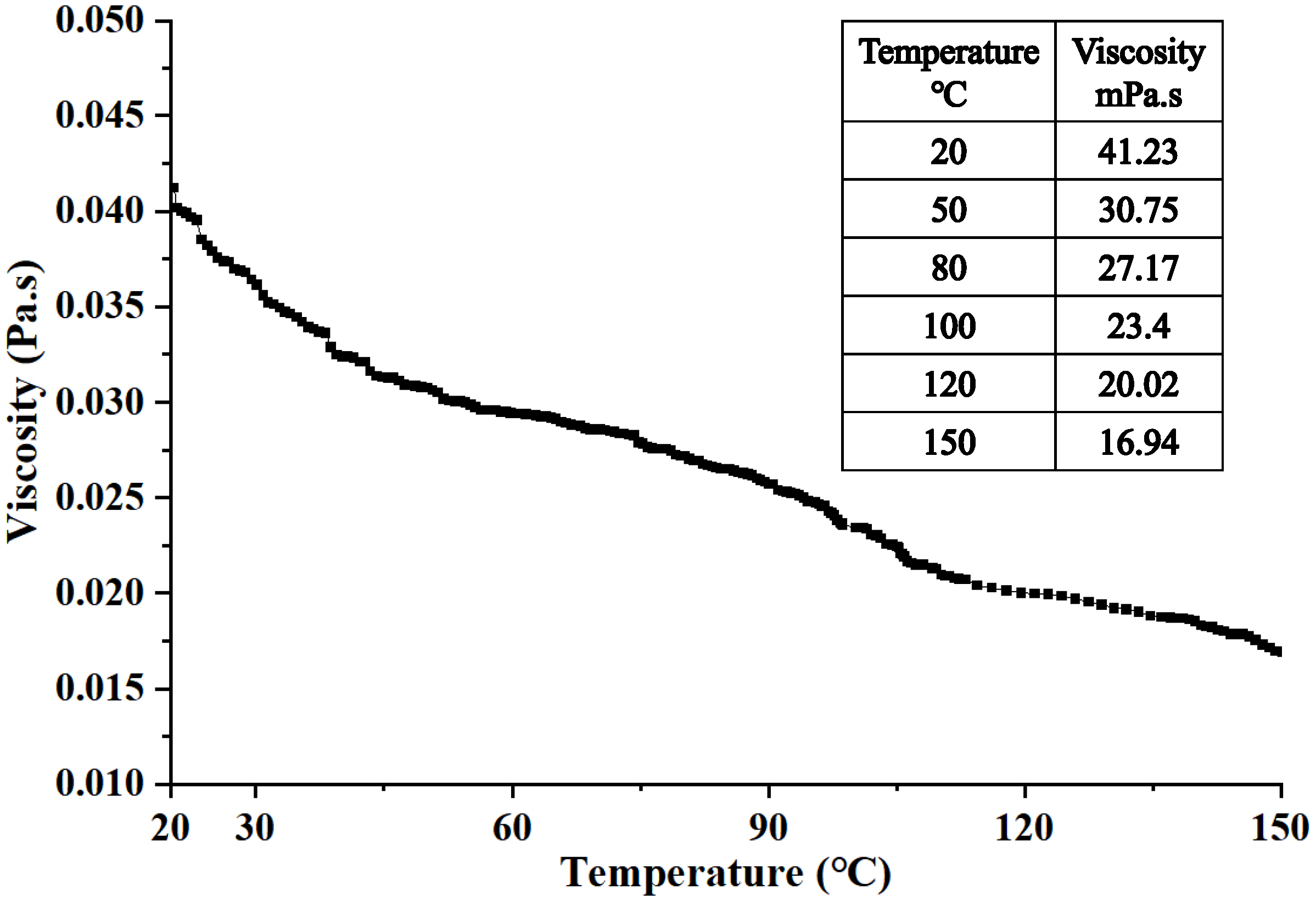
The viscosity–temperature curve of the hydraulic oil is shown in Figure 4. It is shown that the viscosity of the hydraulic oil decreases significantly with increasing temperature. The viscosity at ambient temperature is 41.23 mPa·s, whereas it drops to only 16.94 mPa·s when the temperature reaches 150 °C. This represents a reduction of 59.49% compared with the viscosity at 20 °C.

4.2. Thermal Expansion Performance of Metal Components

Due to differences in the thermophysical properties of the materials, various components of the drilling jar undergo thermal expansion under temperature gradients. This leads to changes in the geometry and dimensions of the flow channels within the jar’s throttle valve, ultimately resulting in significant variations in its throttling performance. Therefore, in accordance with ASTM E228 [28], thermal expansion coefficient tests were conducted for the center valve and throttle valve of the drilling jar. A schematic diagram of the sample is shown in Figure 5. The heating rate was set to 5 °C/min, and the test environment was air.
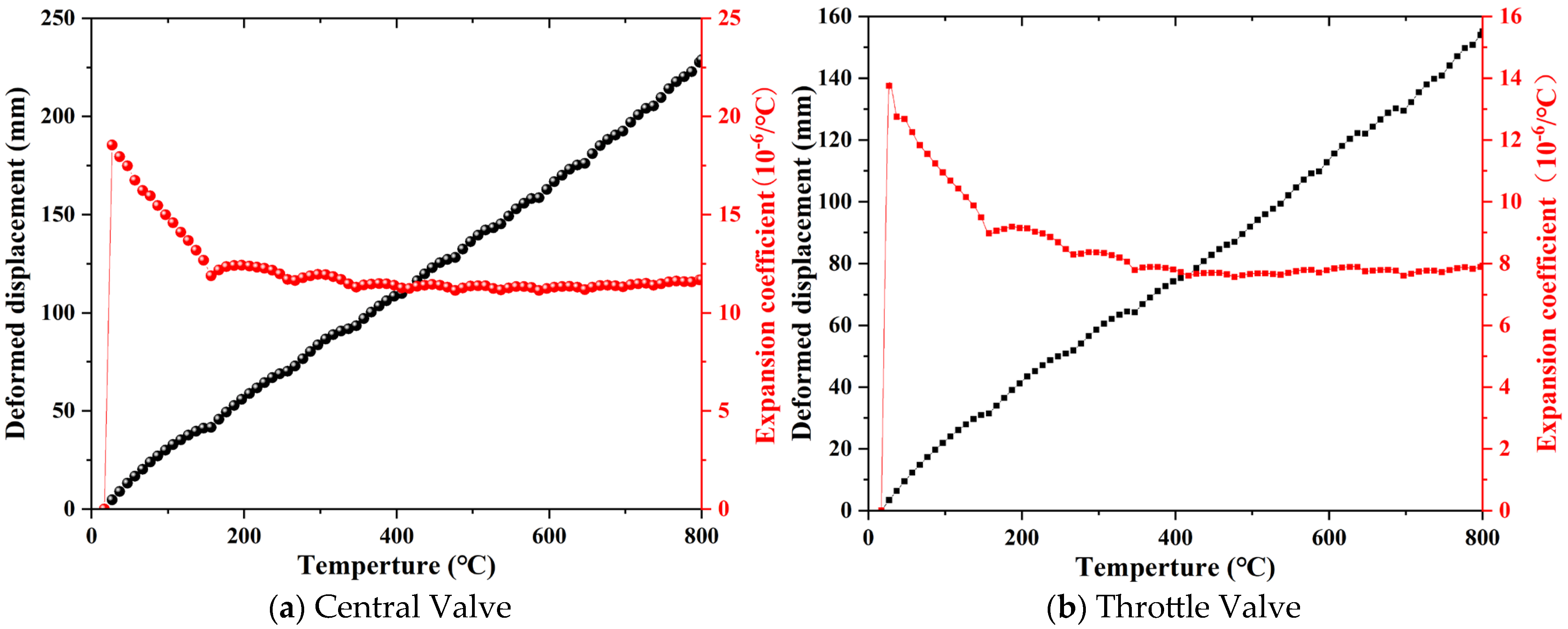
Figure 6 shows the variation curves of the linear thermal expansion coefficient with temperature for the throttle valve and center valve. As observed from the figure, the deformation of both materials increases continuously with rising test temperature. In the temperature range of 0–200 °C, the linear thermal expansion coefficients of both materials exhibit a significant decreasing trend as temperature increases. When the temperature exceeds 200 °C, the coefficients gradually approach a stable state. According to the test results listed in Table 1, the average linear thermal expansion coefficient of the throttle valve material within the 20–150 °C range is 11.35 × 10⁻⁶/°C, while that of the center valve material is 15.51 × 10⁻⁶/°C.

5. Numerical Simulation

5.1. Simulation Model

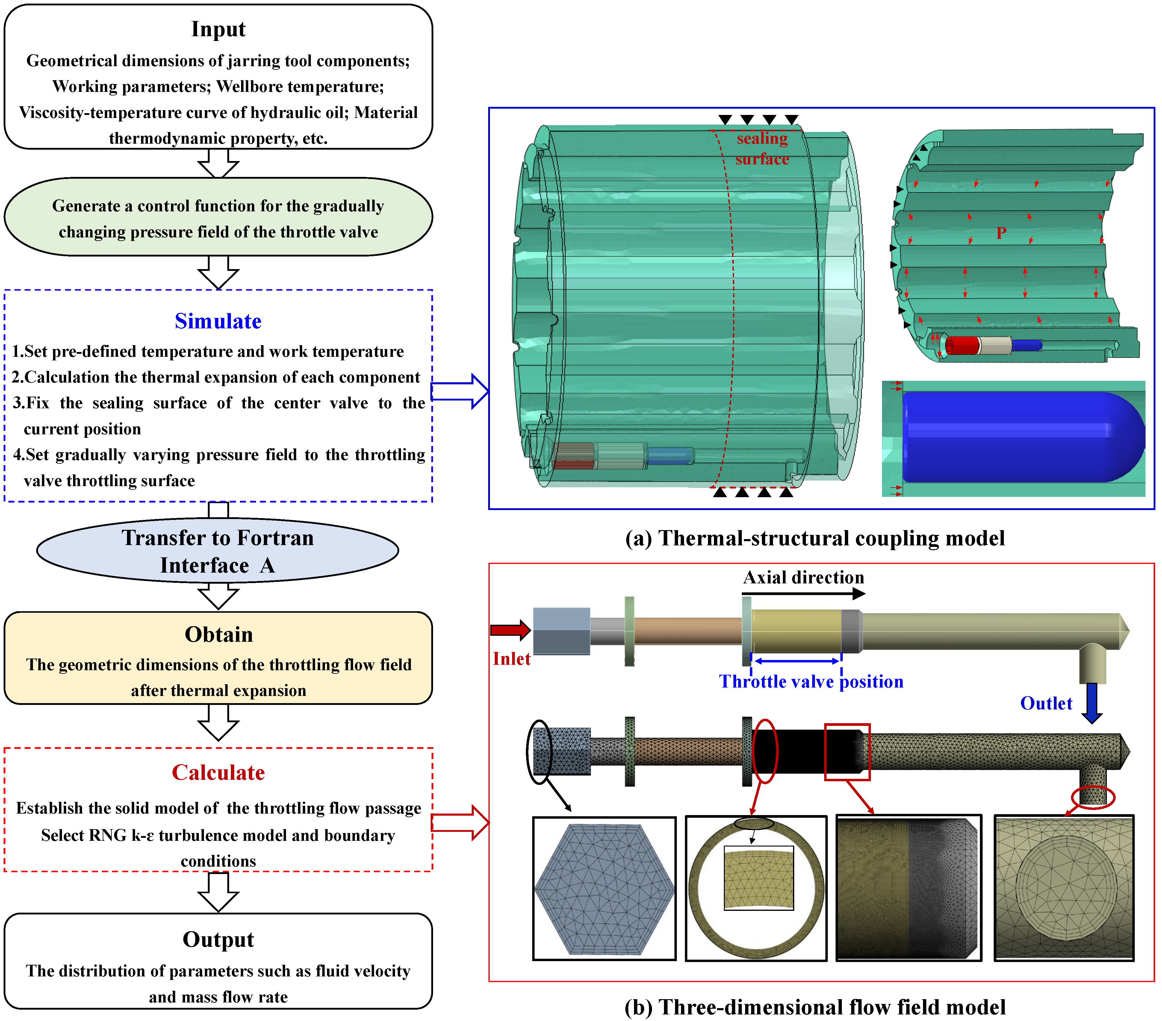
A high-temperature degradation evaluation model for throttling performance is developed by incorporating component thermal expansion and fluid rheological property variation under high-temperature conditions, as shown in Figure 7. Since the throttling passage is significantly narrower than other flow paths, the analysis is divided into two stages here, including thermo-mechanical coupling of components and flow field simulation for throttling performance. Specifically, after completing the thermo-mechanical coupling analysis of the throttling valve body, a FORTRAN program is used to automatically extract the nodal coordinates of the flow field within the throttling valve, thereby obtaining the geometrical information of the thermally deformed throttling passage.
The high-temperature degradation evaluation procedure is detailed as follows: First, assuming that all other sealing components maintain reliable sealing performance and the hydraulic cylinder meets strength requirements, the flow resistance generated within the throttling passage is regarded as equivalent to the triggering load for both upward and downward impacts. Based on this assumption, a pressure gradient function along the throttling passage is established. In the thermo-mechanical coupling analysis, a predefined temperature field is applied to simulate the initial thermal state of the jar prior to being run into the wellbore. Subsequently, the wellbore temperature is imposed on the throttling components to enable the free thermal expansion of key parts, such as the central valve and throttling valve. Then, the sealing surface of the central valve body is fixed at its current position, and fluid pressure is applied to the inner surface of the central valve and the flow channel walls. Meanwhile, pressure following the established pressure gradient is applied to the outer wall of the throttling valve to simulate the geometric deformation induced by fluid pressure. In the flow field analysis, pressure boundary conditions are applied at the inlet and outlet according to the jarring trigger load, while all other surfaces are treated as no-slip walls. The specific boundary condition parameters are listed in Table 2.
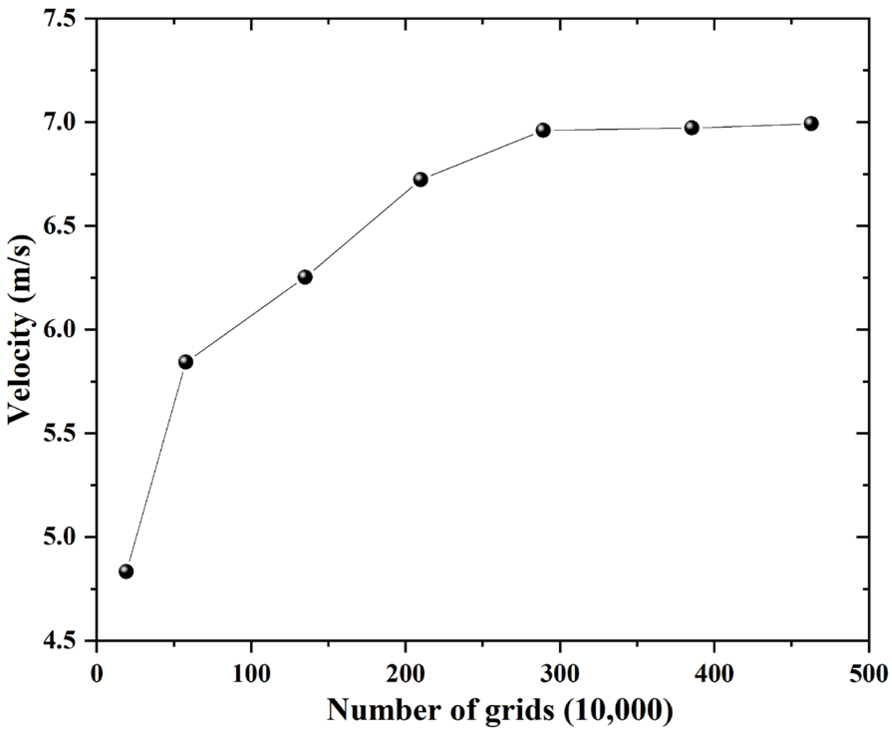
Due to the geometric complexity of the throttling passage, generating high-quality structured hexahedral mesh is challenging. Therefore, tetrahedral elements are adopted for local mesh refinement in the annular flow region near the throttling valve, while structured hexahedral elements are used in regions with relatively smooth geometries. It should be noted that the mesh size and number have a direct impact on both the accuracy and efficiency of the fluid simulation. To ensure the reliability of the numerical results, a mesh independence verification was carried out by comparing models with different mesh densities, as shown in Figure 8, which indicates that when the mesh count increased from 192,800 to 578,300, the average velocity rose significantly from 4.91 m/s to 5.92 m/s. With further increases in mesh count, the velocity continued to rise gradually. However, when the mesh count reached 2,891,800, further mesh refinement had a negligible influence on the velocity results. Therefore, a mesh count of approximately 2,891,800 elements was selected for the subsequent analysis of the throttling flow passage in the drilling jar.

5.2. Simulation Result

5.2.1. Analysis of Throttling Characteristics Under Conventional Working Conditions

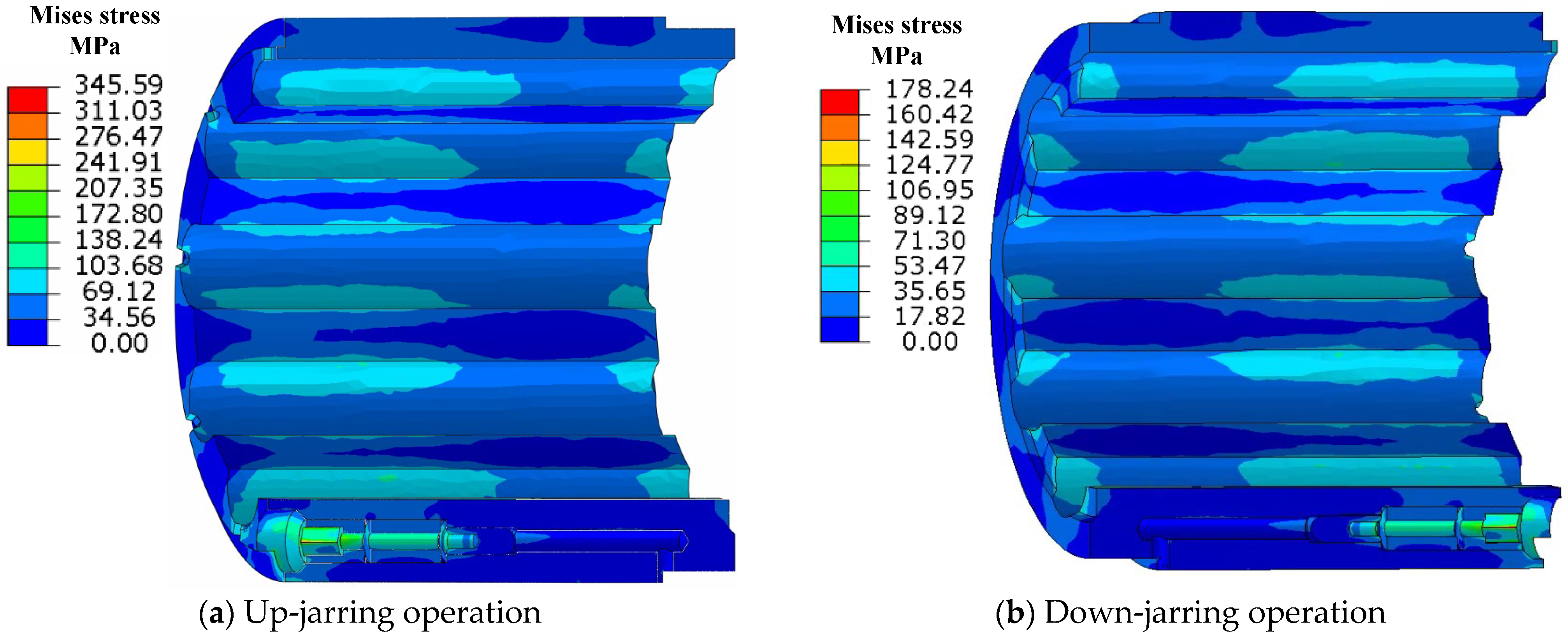
Figure 9 shows the Mises stress distribution contours of the throttling components in the drilling jar at ambient temperature during both up- and down-jarring operations. It can be seen from the figure that the maximum Mises stress is concentrated on the inner wall of the plug due to fluid pressure. However, due to differences in the throttling valve geometry, the hydraulic cylinder pressure during up-jarring is significantly higher than that during down-jarring. As a result, the maximum Mises stress reaches 345.59 MPa during up-jarring, whereas it is limited to 178.24 MPa during down-jarring.
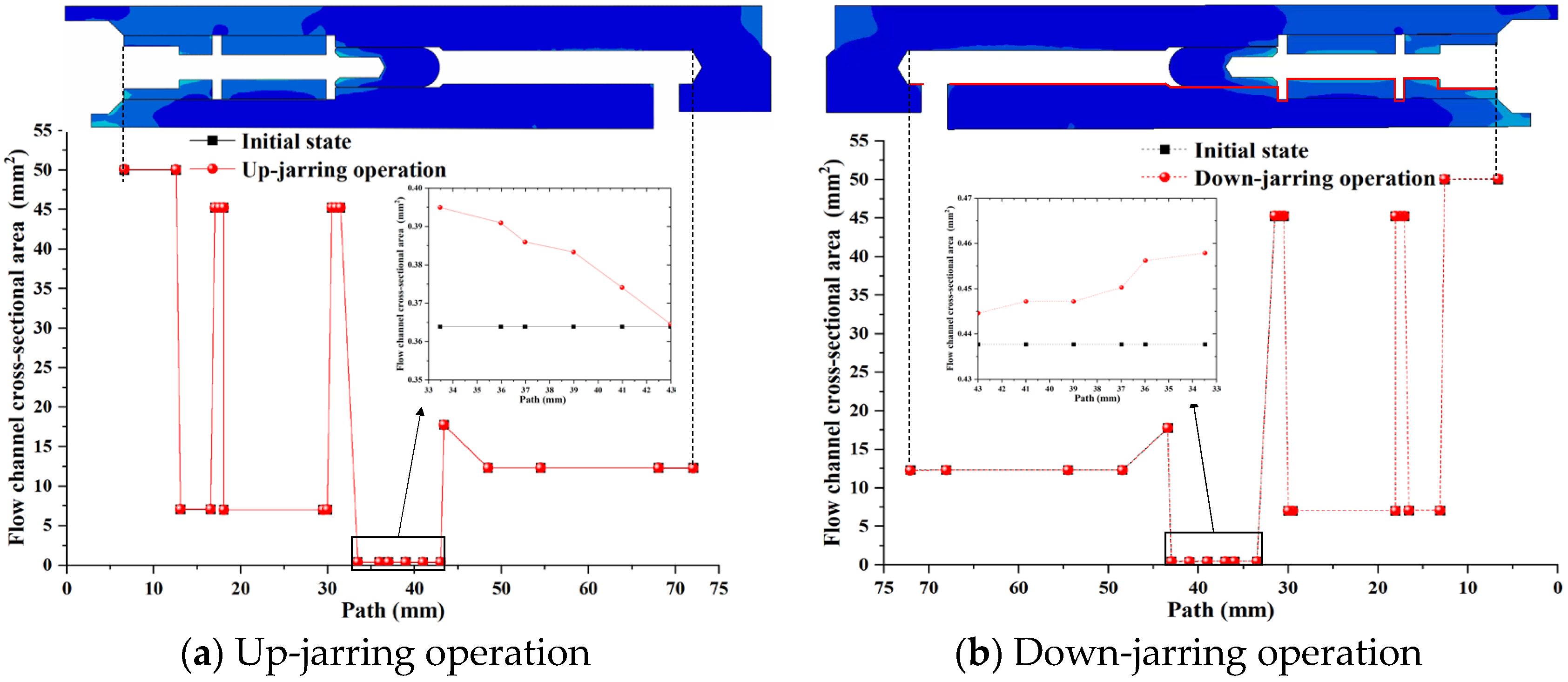
Under ambient temperature conditions, the variation in the geometric characteristics of the throttling flow path in the while-drilling jar is mainly caused by the continuous extrusion of high-pressure fluid during the jarring process. Figure 10 presents the variation curves of the flow passage area along the path of the throttling components during up- and down-jarring operations at ambient temperature. As shown in the figure, the cross-sectional area at each position increases to varying degrees under the action of high-pressure fluid; however, aside from the throttling valve region, changes in other positions are relatively minor. Due to the pronounced throttling effect at the valve, the fluid experiences a significant pressure drop when passing through this area, resulting in a gradual reduction in flow area along the flow direction. Specifically, during the up-jarring operation, the maximum flow area at the valve reaches 0.395 mm2, representing an 8.52% increase compared with the initial area of 0.3608 mm2. In the down-jarring operation, the maximum flow area reaches 0.458 mm2, showing a 3.51% increase over the initial value. These results indicate that the geometric variation of the throttling channel is closely correlated with the fluid pressure distribution.
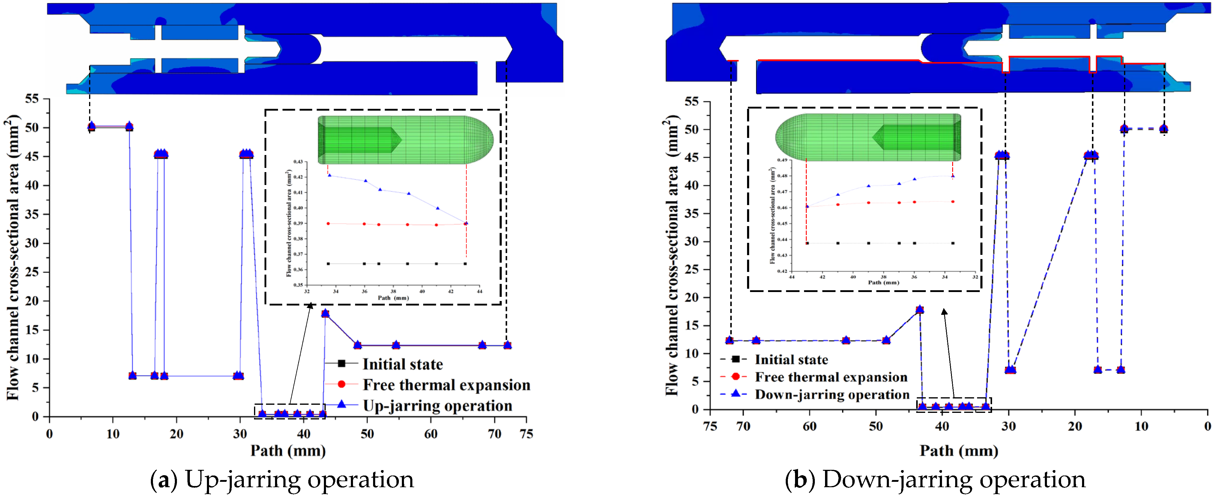
In contrast, under high-temperature downhole conditions, the throttling components experience initial deformation due to free thermal expansion before jarring begins, resulting in a preliminary increase in the throttling channel area. During the jarring operation, the continued extrusion from high-pressure fluid causes further deformation, leading to secondary changes in the geometry and area of the throttling channel. Figure 11 illustrates the cross-sectional area variations of the throttling passages at different positions during up- and down-jarring under 150 °C high-temperature conditions. It can be observed that, during the thermal expansion stage, due to differences in the thermophysical properties of the materials, the overall passage area increases slightly. As the high-pressure fluid exerts continued force, the area expands further. However, due to the pressure drop caused by the throttling effect, the flow passage area still gradually decreases along the flow direction. Specifically, under high-temperature up-jarring, the average throttling area reaches 0.4082 mm2, representing a 13.14% increase compared with the room-temperature value of 0.3608 mm2. In the down-jarring process, the average throttling area is 0.4718 mm2, which is 6.62% higher than the ambient condition value of 0.4425 mm2.

5.2.2. Distribution Characteristics of the Throttle Valve Flow Field

Figure 12 presents the pressure distribution contours of the internal flow field within the throttling components during the up- and down-jarring operations. A significant pressure drop is observed in the throttling flow passage of the hydraulic chamber during both operations. Based on the pressure distributions at different cross sections of the throttling valve, it is evident that the pressure at the inlet (Section A) remains consistent with that of the upper high-pressure chamber. However, the pressure at the midsection (Section B) and the outlet (Section C) gradually decreases, with the outlet pressure approaching 0 MPa, consistent with the pressure in the lower low-pressure chamber. Due to the smooth outer surface of the needle-shaped throttling valve, the pressure drop along the flow direction exhibits a relatively uniform and linear gradient.
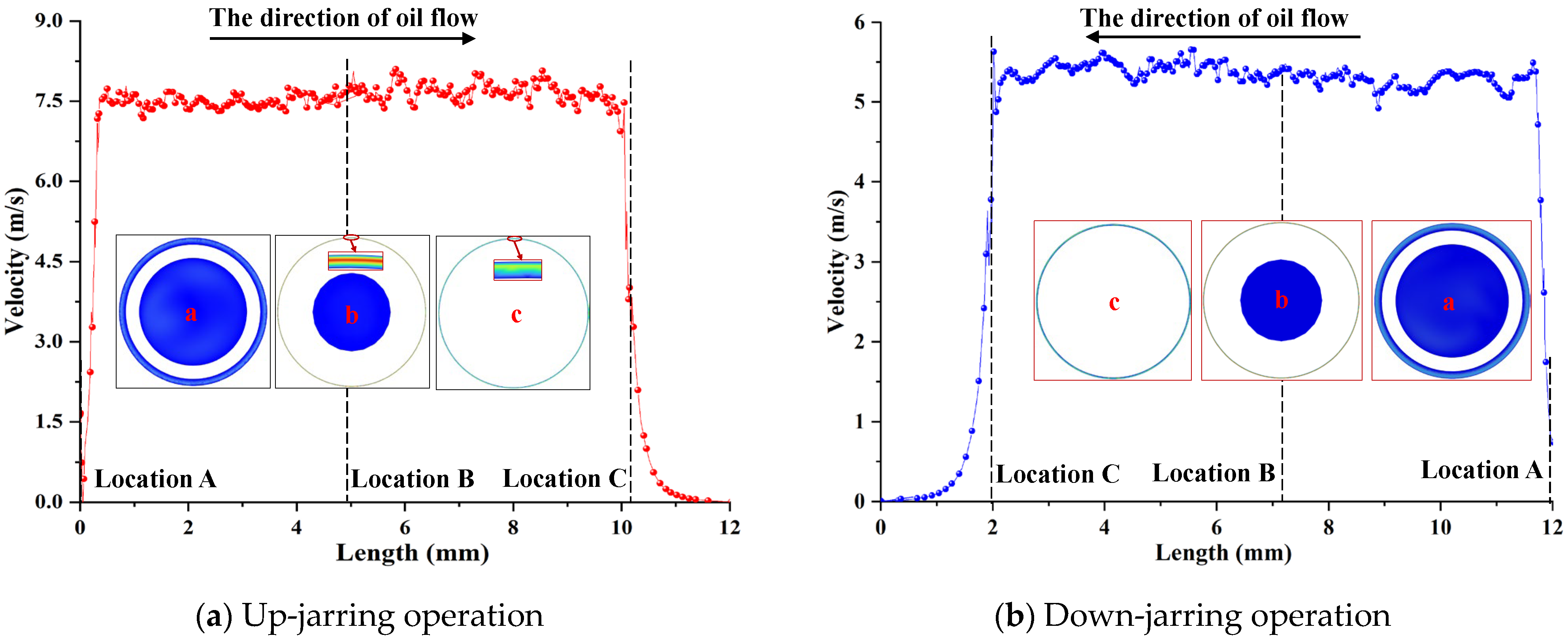
Figure 13 illustrates the variation in fluid velocity along the axial length of the throttling valve during the energy storage stages of both up- and down-jarring operations. It is evident that the high-pressure fluid experiences a sharp acceleration upon entering the throttling passage, followed by slight velocity fluctuations within the passage. As the fluid exits through Section C, the sudden increase in channel cross-sectional area leads to a gradual decrease in velocity, which eventually stabilizes downstream. The maximum fluid velocities reach 8.1 m/s during the upward jarring process and 5.67 m/s during the downward jarring process. These results indicate that the fluid velocity is highly sensitive to the structural parameters of the throttling valve.

5.2.3. The High-Temperature Sensitivity of Throttling Performance

Compared with other components, the narrow flow passage causes the throttling valve to experience a significant pressure drop during jarring. Hence, the geometry of the throttling passage directly governs the throttling performance. However, due to the differences in material properties between the throttling valve and the central valve, the geometric profile and flow area of the throttling path are significantly affected under high-temperature conditions. This is primarily due to the combined effects of thermal expansion and fluid pressure. Therefore, a high-temperature sensitivity analysis of throttling performance is necessary.
Figure 14 presents the variation of cross-sectional area along the throttling passage at elevated temperatures during both up- and down-jarring. With increasing temperature, the throttling area increases significantly while exhibiting a decreasing trend along the flow direction. This behavior suggests that pressure-induced deformation and thermal expansion together contribute to the enlargement of the flow area. At 150 °C, the maximum, minimum, and average throttling areas during upward jarring are 0.4211 mm2, 0.3901 mm2, and 0.4082 mm2, respectively, indicating a 13.14% average increase. For downward jarring, the values are 0.4797 mm2, 0.4567 mm2, and 0.4718 mm2, corresponding to a 5.59% average increase. Compared with the ambient-temperature case, the increase in flow area under high-temperature conditions is significantly greater, indicating that thermal expansion has a more pronounced impact on throttling geometry than fluid pressure alone.
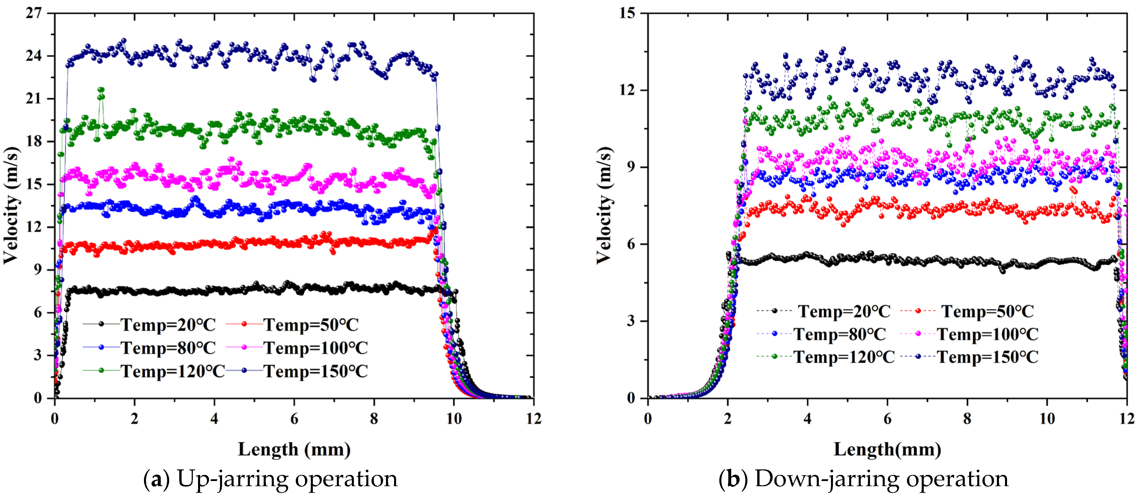
Figure 15 displays the variation in fluid velocity along the throttling path under high-temperature conditions. As temperature increases, the enlarged throttling area and reduced viscosity of the hydraulic fluid result in a substantial increase in flow velocity through the valve. Specifically, when the temperature reaches 150 °C, the maximum fluid velocity during upward jarring increases to 25.07 m/s, while during downward jarring, it rises to 13.61 m/s, corresponding to 3.1 and 2.4 times increases, respectively, compared with the values observed under ambient-temperature conditions. These results clearly indicate that the throttling performance of the valve deteriorates significantly at elevated temperatures. The increase in flow velocity not only reflects a reduction in throttling resistance but also leads to intensified turbulence and flow instability within the throttling region, as evidenced by more pronounced velocity fluctuations and the emergence of localized flow disturbances.
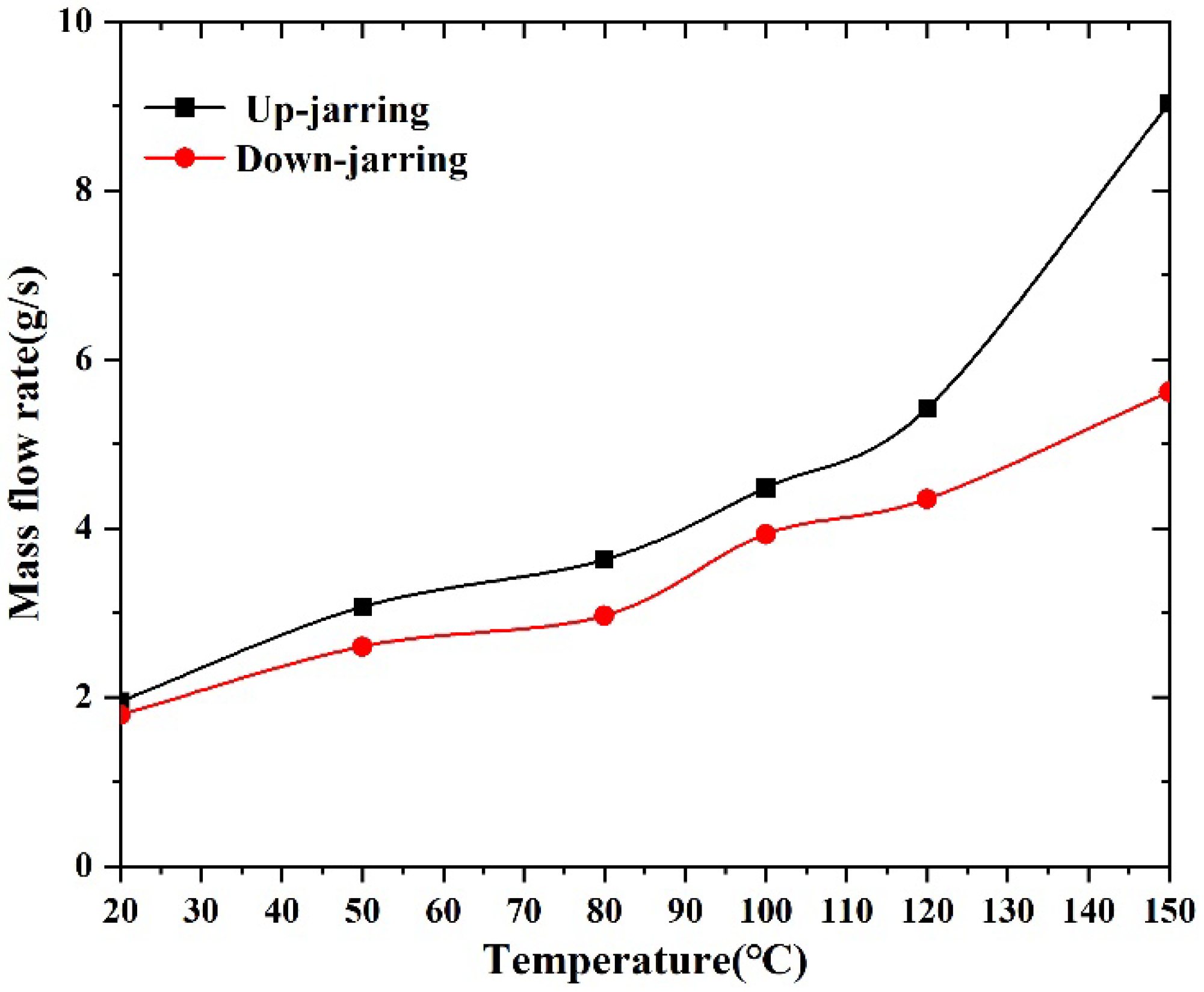
To evaluate the influence of temperature variation on the throttling performance of a hydraulic-while-drilling jar, the characteristic curves of the hydraulic oil mass flow rate at the jar outlet during up- and down-jarring operations were extracted and analyzed at various temperatures, as shown in Figure 16. The results demonstrate that the mass flow rate at the throttling valve outlet increases significantly with rising temperature, indicating a notable reduction in throttling resistance under high-temperature conditions. Specifically, as the temperature increases from 20 °C to 150 °C, the mass flow rate during upward jarring increases from 1.95 g/s to 9.03 g/s, representing a 363.08% increase. During downward jarring, the flow rate rises from 1.79 g/s to 5.61 g/s, corresponding to a 213.41% increase. These findings suggest that elevated temperatures alter the geometry of the throttling passage and reduce the viscosity of the hydraulic oil, thereby significantly enhancing the mass flow rate through the throttling valve. Consequently, this may lead to a substantial decrease in the energy storage duration and jarring delay time of the tool, ultimately affecting the jarring rhythm and impact intensity.

6. Conclusions

In this paper, the high-temperature degradation of the throttling performance of a hydraulic-while-drilling jar was systematically investigated by considering both the thermal expansion of structural components and the high-temperature rheological behavior of hydraulic oil. The geometric variation of the throttling passage was treated as a coupling mechanism that integrates the thermo-mechanical deformation of the valve body with the evolution of the internal flow field. Simulation results show that, during up- and down-jarring operations, the fluid pressure continuously decreases along the flow direction, while the velocity sharply increases upon entering the throttling passage and exhibits slight fluctuations due to shear effects within the channel. Compared with ambient conditions, the viscosity of hydraulic oil significantly decreases with increasing temperature, and thermal expansion of the throttling components leads to enlarged flow areas. As a result, both flow velocity and mass flow rate increase markedly under high-temperature conditions, leading to a significant reduction in throttling performance. Moreover, while the free thermal expansion of the valve body generally enlarges the throttling passage area, pressure-induced deformation during jarring also alters the geometric distribution of the throttling passage. To improve the throttling performance of HWD jars under high-temperature conditions, temperature-sensitive or low-expansion materials should be considered in the structural design to control geometric variations and offset the adverse effects of fluid rheological degradation, thereby ensuring more reliable jarring tool performance for downhole high-temperature operations.

Author Contributions

Conceptualization, Z.L.; methodology, Z.Z.; software, J.N., and Z.Z.; validation, Z.W., Z.L. and H.Y.; formal analysis, W.S.; investigation, S.L.; resources, H.Y.; data curation, Z.Z. and W.S.; writing—original draft preparation, Z.Z.; writing—review and editing, Z.Z. and Z.W.; supervision, Z.L.; project administration, Z.L. and H.Y.; funding acquisition, H.Y. All authors have read and agreed to the published version of the manuscript.

Funding

This work was financially supported by the National Natural Science Foundation of China (Nos. 51974271 and 52104008). We gratefully acknowledge this.

Data Availability Statement

Data are contained within the article.

Conflicts of Interest

The authors declare that they have no known competing financial interests or personal relationships that could have appeared to influence the work reported in this paper.

References

  1. Mercado, J.L. Planning for Successful Jarring Operations-Effective Use of Drilling Impact System Helps Release Stuck Pipe. Presented at the SPE/IADC Drilling Conference and Exhibition, Amsterdam, The Netherlands, 5–7 March 2013. [Google Scholar]
  2. Li, Q.C.; Zhao, D.F.; Yin, J.K.; Zhou, X.; Li, Y.; Chi, P.; Han, Y.; Ansari, U.; Cheng, Y. Sediment instability caused by gas production from hydrate-bearing sediment in Northern South China Sea by horizontal wellbore: Evolution and mechanism. Nat. Resour. Res. 2023, 32, 1595–1620. [Google Scholar] [CrossRef]
  3. Li, Q.; Li, Q.C.; Wang, F.L.; Xu, N.; Wang, Y.; Bai, B. Settling behavior and mechanism analysis of kaolinite as a fracture proppant of hydrocarbon reservoirs in CO2 fracturing fluid. Colloids Surf. A Physicochem. Eng. Asp. 2025, 724, 137463. [Google Scholar] [CrossRef]
  4. Evans, C.D.; Reitsma, R.; Ramsay, E. Reducing Safety Incidents While Lifting and Handling Drilling Jars: A Case Study. Presented at the SPE Middle East Oil and Gas Show and Conference, Manama, Bahrain, 25–28 September 2011. [Google Scholar]
  5. Oliveira, V.C.; Martinez, M.A.; Zahrani, B.S.; Abouelnaaj, K.K. A Study of Drilling Jar Utilization and Effectiveness in the Kingdom of Saudi Arabia. Presented at the SPE Oil and Gas India Conference and Exhibition, Mumbai, India, 4–6 April 2017. [Google Scholar]
  6. Fu, Y.K.; Liu, Q.Y.; Wang, G.R. Mathematical Modeling and Validation on a New Valve Core of the Throttle Valve in MPD. Adv. Mech. Eng. 2013, 5, 125936. [Google Scholar] [CrossRef]
  7. Wang, G.R.; Tao, S.Y.; Liu, Q.Y. Experimental Validation on a New Valve Core of the Throttle Valve in Managed Pressure Drilling. Adv. Mech. Eng. 2014, 6, 324219. [Google Scholar] [CrossRef]
  8. Abdelrahman, A.M.; Hussein, I.A.; Nasser, M.S.; Karami, H.; Ahmed, R. CFD modeling of particle settling in drilling fluids: Impact of fluid rheology and particle characteristics. J. Pet. Sci. Eng. 2021, 199, 108326. [Google Scholar] [CrossRef]
  9. Boyko, E. Interplay between complex fluid rheology and wall compliance in the flow resistance of deformable axisymmetric configurations. J. Non-Newton. Fluid Mech. 2025, 336, 105380. [Google Scholar] [CrossRef]
  10. Zhang, Z.; Sun, B.J.; Wang, Z.Y. Multiphase throttling characteristic analysis and structure optimization design of throttling valve in managed pressure drilling. Energy 2023, 262, 125619. [Google Scholar] [CrossRef]
  11. Wang, X.D.; Li, Y.; Gao, Y.; Gao, C.; Fu, W. DSMC Simulation of the Effect of Needle Valve Opening Ratio on the Rarefied Gas Flows inside a Micronozzle with a Large Length-to-Diameter Ratio. Aerospace 2023, 10, 126. [Google Scholar] [CrossRef]
  12. Singh, D.; Aliyu, A.M.; Charlton, M.; Mishra, R.; Asim, T.; Oliveira, A.C. Local multiphase flow characteristics of a severe-service control valve. J. Pet. Sci. Eng. 2020, 195, 107557. [Google Scholar] [CrossRef]
  13. Okhotnikov, I.; Noroozi, S.; Sewell, P.; Godfrey, P. Evaluation of steady flow torques and pressure losses in a rotary flow control valve by means of computational fluid dynamics. Int. J. Heat Fluid Flow 2017, 64, 89–102. [Google Scholar] [CrossRef]
  14. Ye, J.J.; Cui, J.x.; Hua, Z.; Xie, J.; Peng, W.; Wang, W. Study on the high-pressure hydrogen gas flow characteristics of the needle valve with different spool shapes. Int. J. Hydrogen Energy 2023, 48, 11370–11381. [Google Scholar] [CrossRef]
  15. Zhao, J.G.; Zheng, H.T.; Xie, C.; Peng, H. Research on the Throttling Performance and Anti-Erosion Structure of Trapezoidal Throttle Orifices. Energies 2024, 17, 3196. [Google Scholar] [CrossRef]
  16. Zhu, H.J.; Pan, Q.; Zhang, W.; Feng, G.; Li, X. CFD simulations of flow erosion and flow-induced deformation of needle valve: Effects of operation, structure and fluid parameters. Nucl. Eng. Des. 2014, 273, 396–411. [Google Scholar] [CrossRef]
  17. Wu, Z.; Lu, Y.F.; Liu, M.; Wang, F.; Wang, Y.; Du, S.; Wang, W.; Hong, B. The Erosion Characteristics of a Needle Throttle Valve with Multiple Placement Schemes in a Shale Gas Field Based on CFD-DEM. Processes 2025, 13, 1833. [Google Scholar] [CrossRef]
  18. Zhao, Z.H.; Wu, Z.; Wang, W.; Wang, X.; Du, S.; Chen, X.; Li, P.; Wang, Y. CFD-DPM Model of Gas–Solid Two-Phase Flow Erosion of Needle Throttle Valve. Coatings 2025, 15, 248. [Google Scholar] [CrossRef]
  19. Kibar, A.; Korkmaz, Y.S.; Yigit, K.S. Flow Analysis of a Needle Type Throttle Valves via Experimental and Numerical Methods. Iran. J. Sci. Technol. Trans. Mech. Eng. 2024, 49, 429–444. [Google Scholar] [CrossRef]
  20. Ye, Y.G.; Fan, H.H.; Liu, Y.H. A new approach for predicting the rheological properties of oil-based drilling fluids under high temperature and high pressure based on a parameter-free method. Appl. Sci. 2023, 13, 8592. [Google Scholar] [CrossRef]
  21. Hou, C.W.; Qian, J.Y.; Chen, F.; Jiang, W.; Jin, Z. Parametric analysis on throttling components of multi-stage high pressure reducing valve. Appl. Therm. Eng. 2018, 128, 1238–1248. [Google Scholar] [CrossRef]
  22. Chen, F.Q.; Jin, Z.J. Fluid dynamics analysis and optimized throttling design of L-shaped multi-stage high pressure reducing valve. Flow Meas. Instrum. 2023, 89, 102296. [Google Scholar] [CrossRef]
  23. Chen, F.Q.; Ren, X.D.; Hu, B.; Li, X.; Gu, C.; Jin, Z. Parametric analysis on multi-stage high pressure reducing valve for hydrogen decompression. Int. J. Hydrogen Energy 2019, 44, 31263–31274. [Google Scholar] [CrossRef]
  24. Al Alsayednassir, A.; Alvarez, O.; Aitmaganbetov, S.; Radhakrishnan, V. Enhancing Impact Tool Reliability and Efficiency: Advances in Technology and Design. In Proceedings of the SPE 225706, SPE/IADC Middle East Drilling Technology Conference and Exhibition, Abu Dhabi, United Arab Emirates, 27–29 May 2025. [Google Scholar]
  25. Chen, F.; Jin, Z. Throttling components effect on aerodynamic performance of superheated steam flow in multi-stage high pressure reducing valve. Energy 2021, 230, 120769. [Google Scholar] [CrossRef]
  26. Darmawan, S.; Tanujaya, H. CFD investigation of flow over a backward-facing step using an RNG k-ε turbulence model. Int. J. Technol. 2019, 10, 280–289. [Google Scholar]
  27. ASTM D2270; Standard Test Method for Calculating Viscosity Index from Kinematic Viscosity at 40 and 100 °C. ASTM International: West Conshohocken, PA, USA, 2016.
  28. ASTM E228; Standard Test Method for Linear Thermal Expansion of Solid Materials with a Push-Rod Dilatometer. ASTM International: West Conshohocken, PA, USA, 2016.
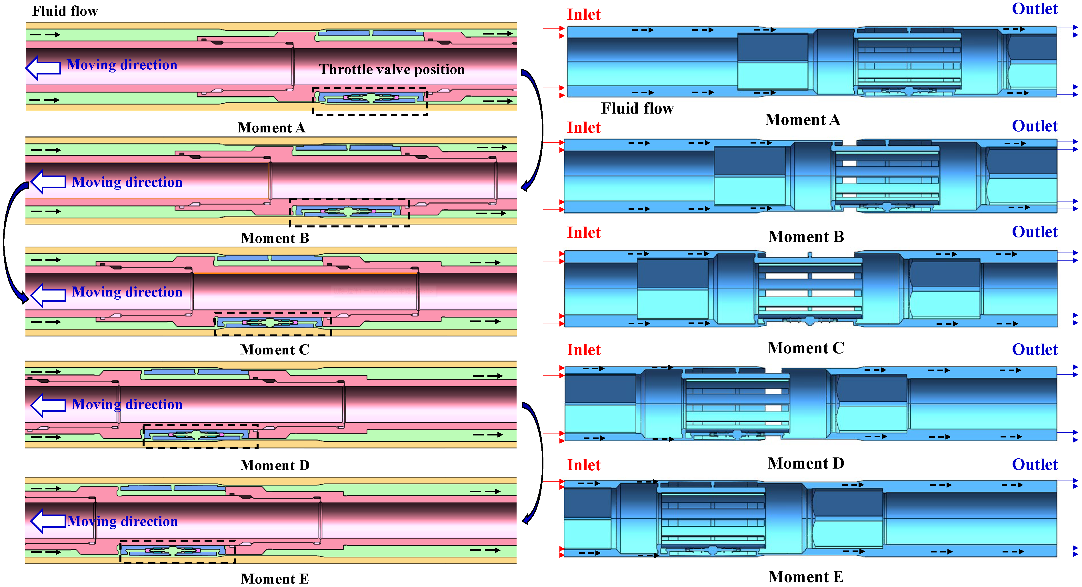
Figure 1. Evolution of the internal flow field within the hydraulic-while-drilling jarring tool during the up-drilling operation.
Machines 13 00824 g001
Figure 2. Geometric schematic diagram of the throttle valve section.
Machines 13 00824 g002
Figure 3. Viscosity testing device for hydraulic oil in a high-temperature environment.
Machines 13 00824 g003
Figure 4. The viscosity–temperature curve of the hydraulic oil.
Machines 13 00824 g004
Figure 5. Schematic diagram of thermal expansion test for the throttle valve components.
Machines 13 00824 g005
Figure 6. Variation curves of thermal expansion coefficients for throttle valve and central valve (The red curve represents the thermal expansion coefficient, while the black curve represents the deformation displacement).
Machines 13 00824 g006
Figure 7. The high-temperature degradation evaluation model for throttling performance.
Machines 13 00824 g007
Figure 8. The relationship between mesh count and fluid velocity.
Machines 13 00824 g008
Figure 9. The Mises stress distribution contours of the throttling components in the drilling jar at ambient temperature.
Machines 13 00824 g009
Figure 10. The variation curves of the flow passage area along the path of the throttling components during up- and down-jarring operations at ambient temperature.
Machines 13 00824 g010
Figure 11. The cross-sectional area variations of the throttling passages at different positions during up- and down-jarring under high-temperature conditions.
Machines 13 00824 g011
Figure 12. The pressure distribution contours of the internal flow field within the throttling components.
Machines 13 00824 g012
Figure 13. The variation in fluid velocity along the axial length of the throttling valve during the energy storage stages.
Machines 13 00824 g013
Figure 14. The variation of cross-sectional area along the throttling passage at elevated temperatures during jarring operation.
Machines 13 00824 g014
Figure 15. The variation in fluid velocity along the throttling path under high-temperature conditions.
Machines 13 00824 g015
Figure 16. The curves of the hydraulic oil mass flow rate at the jar outlet during up- and down-jarring operations.
Machines 13 00824 g016
Table 1. Test results of thermal expansion coefficients for throttle valve and central valve materials.
TypeTemperature
20–150 (10−6/°C)20–500 (10−6/°C)20–800 (10−6/°C)
Throttle Valve11.359.088.57
Central Valve16.712.7412.21
Table 2. The boundary condition parameters.
ParameterInitial Temperature/°CWellbore Temperature/°CUpward Triggering Load/kN
Value20150350
Downward triggering load/kNUp-jarring inlet pressure/MPaDown-jarring inlet pressure/MPaOutlet pressure
/MPa
18042.0621.610
Disclaimer/Publisher’s Note: The statements, opinions and data contained in all publications are solely those of the individual author(s) and contributor(s) and not of MDPI and/or the editor(s). MDPI and/or the editor(s) disclaim responsibility for any injury to people or property resulting from any ideas, methods, instructions or products referred to in the content.