Article

Coordinated Motion Pattern of Dual Forging Manipulators Based on Forging Deformation Behavior and Press Kinematics

1
School of Mechanical Engineering, Yanshan University, Qinhuangdao 066004, China
2
Beijing Research Institute of Automation for Machinery Industry Co., Ltd., Beijing 100120, China
3
Hebei Innovation Center for Equipment Lightweight Design and Manufacturing, Qinhuangdao 066004, China
*
Author to whom correspondence should be addressed.
Machines 2025, 13(9), 816; https://doi.org/10.3390/machines13090816
Submission received: 7 July 2025 / Revised: 2 September 2025 / Accepted: 3 September 2025 / Published: 5 September 2025
(This article belongs to the Section Automation and Control Systems)

Abstract

To address the challenges of short allowable motion windows and complex motion planning inherent in dual forging manipulator systems, this study proposes a coordinated motion pattern tailored to dual-manipulator operations, focusing on forging deformation behavior and press control characteristics. First, six representative long-shaft forging materials were classified based on typical industrial applications. Using DEFORM-3D (V11.0) software, the deformation process during the elongation operation was analyzed, and the velocity and displacement characteristics at both ends of the forgings were extracted to clarify the compliant motion requirements of the grippers. Next, a segmented computation method for manipulator allowable motion time was developed based on the motion–time curve of the hydraulic press, significantly improving the time utilization efficiency for coordinated control. Furthermore, experimental tests were carried out to verify the dynamic response performance and motion accuracy of the dual-manipulator system. Finally, the dual-manipulator forging cycle was systematically divided into four stages—pre-forging adjustment, inter-pass compliance, execution phase, and forging completion—resulting in a structured and implementable coordination control framework. This research provides both a theoretical foundation and practical pathway for achieving efficient and precise coordinated motion control in dual forging manipulator systems, offering strong potential for engineering application and industrial deployment.

1. Introduction

Forging manipulators are essential equipment in forging workshops, operating in coordination with hydraulic presses to clamp, position, and feed workpieces during forging processes. They play a critical role in the production of large-scale forgings and heavy-duty components [1,2,3]. In current industrial practice, a single forging manipulator is commonly used in conjunction with a hydraulic press. However, this single-manipulator mode exhibits notable limitations when handling large and complex forgings, including low production efficiency, high energy consumption, unstable clamping, and inconsistent forming quality [4,5].
In recent years, driven by the increasing demand for manufacturing complex forgings, the dual forging manipulator mode—where two manipulators operate in coordinated linkage with a press—has gained growing attention [6]. In this mode, two manipulators simultaneously clamp the high-temperature workpiece and cooperate with the press to complete the forming process, as illustrated in Figure 1. This approach significantly enhances clamping stability and improves process controllability. However, due to the rigid constraints imposed by dual clamping jaws, multiple constraint conditions can arise, generating interaction forces during deformation that may impede free workpiece deformation and compromise forming accuracy [7]. Moreover, coordination between the two manipulators is typically based on empirical strategies such as alternating operation or standby mode, which are essentially extensions of single-manipulator control and lack a systematic theoretical framework for coordinated motion planning.
During forging, the bilateral constraints imposed by the manipulator jaws require the clamping ends to perform compliant motions in accordance with the deformation behavior of the workpiece to minimize interaction forces. Existing studies have predominantly focused on internal stress evolution and microstructural changes in forgings. For example, Wang et al. employed finite element simulations to investigate the influence of upper die displacement on the deformation of mandrel forgings and proposed a new symmetric flipping forging process [8]; Cai et al. developed a high-temperature constitutive model for TC17 titanium alloy and revealed the effects of strain rate on flow stress behavior [9]; and Rahul et al. used finite element methods to simulate material flow and strain distribution during thermal deformation, providing theoretical support for process optimization [10]. Although these studies provide valuable insights into microscopic deformation behavior, their practical applicability to motion planning in dual-manipulator systems remains limited.
At the macroscopic level, some researchers have developed predictive models of end-deformation behavior using approaches such as spread coefficient models and principal stress methods. For instance, Yan proposed a spread coefficient-based model to predict metal flow and established a motion profile prediction framework for clamping ends [11]; Pinto et al. designed an engineering-oriented compliant feeding strategy to accommodate elongation deformation in forging manipulators [12]; and Şimşir et al. applied the principal stress method along with empirical formulas to derive stress and velocity distributions during bar forging processes [13]. These approaches provide valuable methodological references for this study. Building on these insights, this paper employs numerical simulation to analyze the end-deformation displacements and velocity profiles of typical long-axis forgings, establishing a deformation behavior database to support the inverse design of motion planning strategies for coordinated dual-manipulator operation.
In addition to compliant motion, forging manipulators must achieve high-frequency and tightly synchronized coordination with the hydraulic press throughout the forging cycle to avoid motion conflicts and process errors. Recent studies have begun to address coordinated motion planning under forging cycle constraints. For example, Sciavicco et al. conservatively estimated manipulator working times based on typical press parameters and developed an initial timing relationship model between the press and manipulator [14]. Yao et al. proposed an upward motion profile design for manipulator jaws that considered dynamic response and energy consumption, ensuring non-interference between components and providing an engineering reference for coordinated control [15]. However, these studies largely rely on traditional single-manipulator modes and lack adaptability for complex multi-device coordination or high-frequency forging conditions.
It is important to note that the press generally responds faster than the manipulators. Key parameters such as forging frequency, press stroke, and motion profiles (e.g., trapezoidal or sinusoidal) significantly influence the available time window for clamping actions and the overall forging rhythm. These factors place higher demands on manipulator response time and motion profile planning accuracy [16,17]. Therefore, it is essential to establish precise response time and motion timing models for the manipulators based on press kinematics, thereby enabling efficient and high-quality coordinated control under dual-manipulator operation. In summary, achieving coordinated operation of dual forging manipulators under complex forging conditions requires a systematic study of the macroscopic deformation behavior and timing characteristics of typical forgings under press loading, alongside a clear definition of compliant motion requirements and motion patterns for both manipulators.
In this work, based on the material characteristics of typical forgings, finite element simulations were conducted to analyze the deformation velocity and displacement profiles at both ends of the workpiece. The relationship between deformation behavior and press parameters was quantitatively established. Furthermore, by analyzing the stroke curve of the press, the motion timing sequence of the dual manipulators was reconstructed, and a cycle optimization strategy was proposed to extend the allowable motion time of the manipulators. Experimental validation was performed to confirm the feasibility of the proposed compliant motion strategy. Based on these findings, a coordinated motion pattern consisting of four distinct stages—pre-forging alignment, inter-pass adjustment, execution of forging actions, and post-forging release—was formulated. This study lays a theoretical and methodological foundation for improving the precision and responsiveness of dual-manipulator coordination in advanced forging systems.

2. Materials and Methods

2.1. Analysis of Compliance Motion Requirements for Dual-Manipulator Forging Systems

2.1.1. Structural Composition of the Dual-Manipulator Forging System

The dual forging manipulator system consists of mechanical and hydraulic subsystems. The mechanical subsystem primarily comprises two suspended link mechanisms and two trolley-travel mechanisms on either side of the manipulator. In this study, the suspension systems of both manipulators adopt a DDS-type parallel four-bar linkage configuration. The gripper mechanism integrated into each manipulator is capable of performing clamping, releasing, and rotational actions on the forging.
The motions of the suspension system and the trolley travel are transmitted to the workpiece via the gripper, enabling six degrees of freedom (DOF) manipulation in space, as illustrated in Figure 2. Specifically, the system allows for side swinging, vertical lifting, pitching, lateral offset, rotation, and axial damping actions. These degrees of freedom ensure that the manipulators can accommodate complex forging trajectories and dynamic deformation behaviors during the forming process. The rotational motion of the gripper is actuated by the hydraulic motor; the vertical lifting motion is provided by the lifting hydraulic cylinder; the pitching motion is controlled by the pitching hydraulic cylinder; the lateral offset motion is achieved by two independent hydraulic cylinders; the side-swinging motion of the gripper is driven by the rear hydraulic cylinder; and the forward and backward translational motion along the main beam is powered by the hydraulic motor.

2.1.2. Compliance Modes of the Manipulator

The compliant motion behavior of a single forging manipulator during one forging stroke for long-shaft forgings is illustrated in Figure 3. As the upper die moves downward, the clamping end of the forging undergoes deformation in both the horizontal and vertical directions. Meanwhile, the free end is unconstrained in the horizontal direction and passively follows the vertical motion of the clamped end. Compared to the bilateral constraints applied by the dual-manipulator mode, the single-manipulator configuration imposes lower compliance requirements on the clamping system.
During a single forging stroke, the grippers of the dual forging manipulators remain engaged throughout the process, effectively forming fixed constraints on both ends of the forging. To ensure high-quality forming results, both manipulators must perform compliant motions in multiple directions to accommodate the forging’s deformation. As shown in Figure 2, actuator S1 represents the horizontal compliance cylinder, which controls the gripper’s horizontal response and is connected to a hydraulic buffering system to absorb deformation-induced impacts during forging. Actuator S2 controls vertical compliance through a lifting cylinder that enables the gripper to follow the vertical deformation of the forging.
In the horizontal direction, the compliant motion of the grippers can be realized by a single manipulator or by both manipulators simultaneously. Using the midpoint of the forging length as a reference, the end closer to the die is defined as the near-die end (clamping end), and the opposite is the far-die end (free end). As illustrated in Figure 4, three potential compliant motion modes for the dual grippers are defined: Mode M1—compliance at the near-die end only; Mode M2—compliance at the far-die end only; and Mode M3—simultaneous compliance at both ends.

2.2. Classification and Deformation Simulation of Forged Components

2.2.1. Classification of Typical Large Long-Shaft Forgings

The compliant motion strategy of the manipulators depends fundamentally on the deformation behavior of the forging. Therefore, an analysis of the deformation patterns of large long-shaft forgings is essential. To enhance the general applicability of the simulated deformation data, this study does not focus on a single material. Instead, representative long-shaft forgings commonly used across various industries were selected based on their mechanical properties and typical forming applications.
Key material parameters—such as Young’s modulus, Poisson’s ratio, and forging temperature—were identified according to standard forming processes. Table 1 summarizes typical materials, application fields, and property ranges for representative long-shaft forgings in different industrial sectors. The data presented in Table 1 were obtained through a comprehensive approach that combined literature review, on-site industrial investigations, and technical specifications provided by forging equipment manufacturers. For each category, information on material types, mechanical properties, load characteristics, and application scenarios was summarized based on engineering manuals, relevant industry standards, and field measurements. Each of the three key parameters was categorized into three levels (high, medium, low), as shown in Table 2, to establish a structured classification system.
Based on combinations of mechanical characteristics, typical industrial forging temperatures, and common engineering applications, six representative material parameter sets were formulated to serve as simulation models. The detailed configurations of these six material sets are presented in Table 3.
The classification summarized in the table is based on a comprehensive review of industrial practices and material databases. This system relies on fundamental thermo-mechanical parameters that are widely applicable across metallic materials. Consequently, the proposed methodology is both scalable and adaptable, enabling its application to a broad range of practical industrial scenarios.
For any given large long-shaft forging, if its mechanical properties—such as elastic modulus and Poisson’s ratio—are similar to those of one of the representative sets, and its forging temperature aligns with those specified, the deformation behavior of the forging can be considered to conform to one of the six generalized cases. Accordingly, the corresponding compliant motion strategy for the dual manipulators during forging can be derived from the established deformation patterns associated with that material group.

2.2.2. Finite Element Model

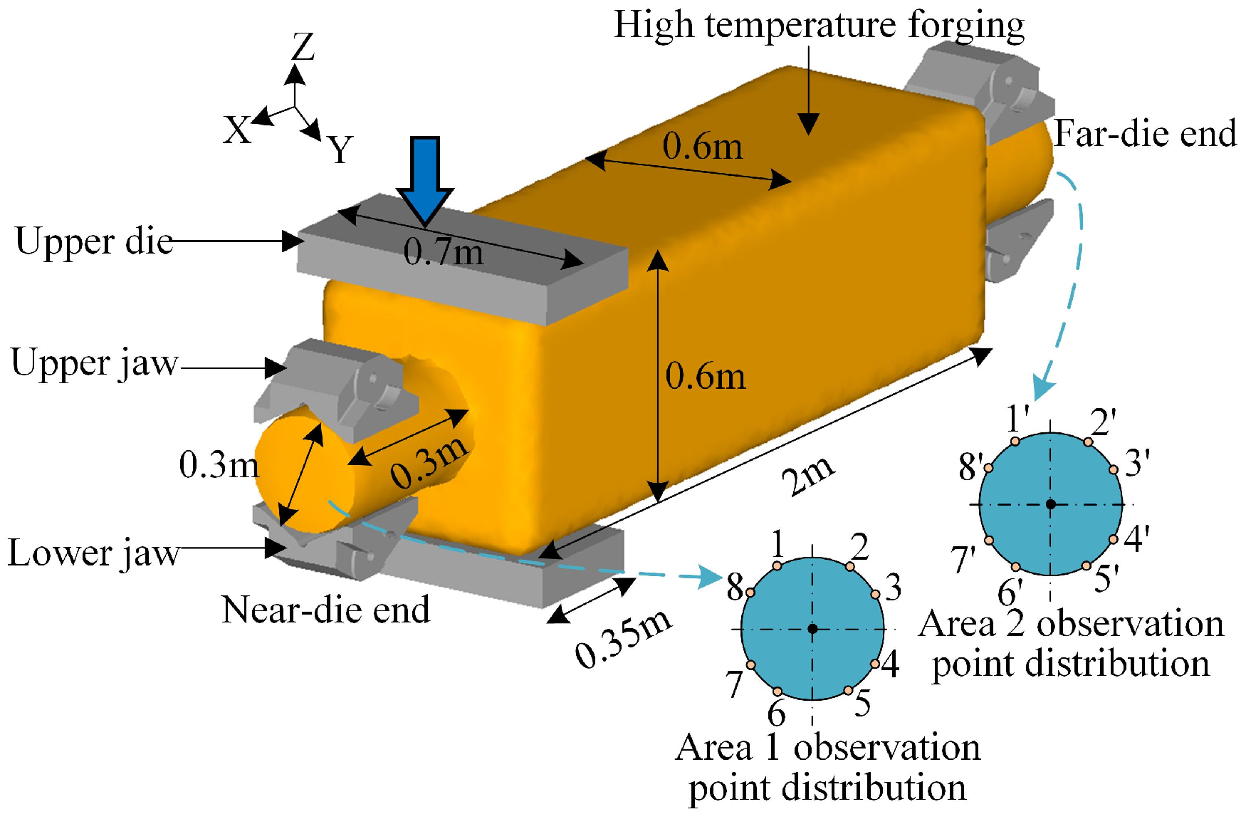
Finite element simulations were conducted using DEFORM-3D (V11.0) to investigate the single-stroke deformation behavior of the six representative material sets under the dual-manipulator mode. A typical upsetting–elongation process using a square billet was selected as the forming scenario. As shown in Figure 5, a finite element (FE) model for dual-manipulator forging was established along with the associated geometric parameters. The die width was set to 350 mm, and the billet dimensions were 2000 mm × 600 mm × 600 mm. In the simulation, the dies and grippers were modeled as rigid bodies, while the billet was modeled as a thermoplastic deformable body with heat conduction capability. The mesh consisted of approximately 150,000 tetrahedral elements, with local refinement to 2–3 mm in regions of severe deformation and at the die–workpiece interfaces to enhance computational accuracy.
The initial billet temperature was assigned according to the material specifications listed in Table 1, while the die temperature was fixed at 300 °C. For example, for TC4 alloy, the initial billet temperature was set at 950 °C. Convective heat transfer between the billet surface and the environment was considered with a heat transfer coefficient of 10 W/(m2·K), and the interfacial heat transfer between the billet and dies was modeled with a coefficient of 3 kW/(m2·K). The flow stress of the billet material was dynamically updated based on the local temperature distribution, enabling the FE model to accurately capture the temperature evolution and deformation behavior during forging. The press stroke and velocity were defined according to actual production parameters, with a maximum downward velocity of 100 mm/s and a deformation depth per forging step equal to 5% of the billet height.
In the simulation model, both the grippers and the die were defined as rigid bodies, while the forging was modeled as a thermoplastic deformable body. Thermal exchange conditions were activated to account for heat transfer during the forging process. The forging was meshed using tetrahedral elements to accurately capture deformation characteristics.
To facilitate the analysis of deformation behavior at both ends of the forging, the high-temperature billet was divided into two regions, as illustrated in Figure 5: (1) the compliance observation region, located at the clamping ends and used to evaluate the compliant motion requirements; and (2) the forging deformation region, where the actual forming occurs. The deformation data extracted from the compliance observation regions were used to characterize the deformation response of large long-shaft forgings under dual-manipulator conditions.

2.3. Calculation of Manipulator Motion Time

The forging frequency of the hydraulic press is typically higher than the response speed of the forging manipulators. Therefore, the press parameters are the primary factors influencing the allowable motion time of the manipulators. This section presents the analysis and segmentation of the press motion–time curve. Under high-speed forging conditions, the press exhibits shorter cycle times, higher deformation speeds, and more frequent interactions with the manipulators compared with conventional forging conditions. The displacement curve is divided into distinct motion phases, and the durations of these phases are quantitatively determined from the time-series data. These intervals provide the basis for defining allowable and restricted motion windows.
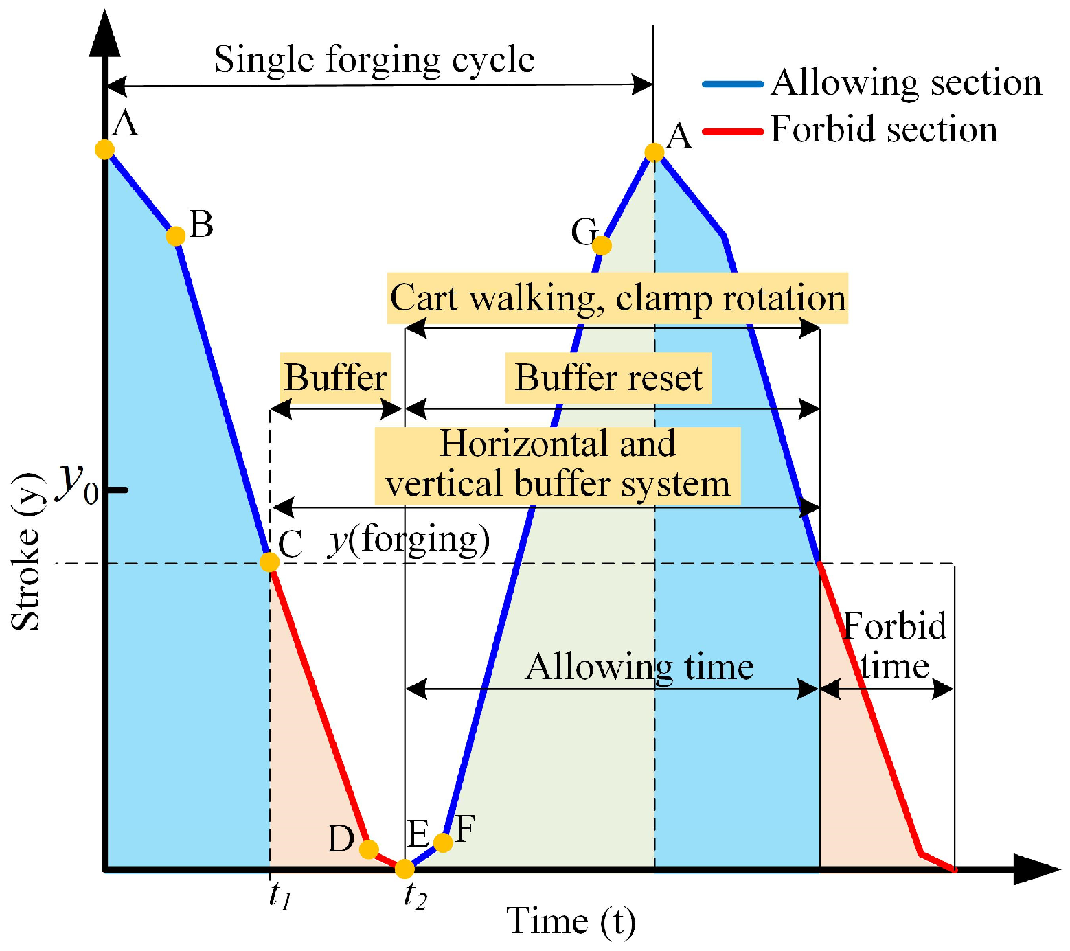
As illustrated in Figure 6, the operational time window of the manipulators under high-speed forging conditions is defined based on the motion profile of the press slide. Figure 6 is generated based on the motion data of the press, where the displacement of the upper die during the forging cycle was recorded. The motion profile is divided into three distinct stages: the idle downward stroke, the deformation stage, and the idle return stroke. This segmentation provides a solid foundation for analyzing the timing coordination between the press and the gripper manipulators. In the diagram, y(forging) denotes the initial height of the workpiece, y0 represents the mid-point position of the press slide, and s is the downward stroke distance. The contact time between the upper die and the forging is denoted as t1, while t2 indicates the time at which the die separates from the forging.
The motion cycle is divided into two segments: the allowable motion interval, during which the upper die is not in contact with the forging and manipulator motion is permitted; the forbidden motion interval, during which the upper die is in contact with the forging and manipulator motion is restricted. Based on this segmentation, a calculation method for determining the manipulator’s allowable motion time under high-speed forging conditions is established as follows:
Since the downward stroke of the hydraulic press can be approximated as a sinusoidal motion, the vertical position of the upper die can be expressed using a standard sine function. In actual forging operations, after each stroke is completed, the upper die returns to the top dead center (TDC), which corresponds to the maximum displacement in the sine wave. Therefore, the adjusted vertical position of the press slide can be defined as:
y ( t ) = y 0 A cos ( ω t )
where y(t) is the vertical position of the upper die at time t (mm), y0 is the mid-stroke position of the press slide (mm), A is the stroke amplitude of the press (mm), and ω is the angular frequency of the press motion (rad/s), which is related to the forging frequency.
The time at which the upper die first comes into contact with the undeformed forging (t1), and the time at which it separates from the deformed forging (t2), can be expressed as:
y ( t 1 ) = y ( t 2 ) = y ( f o r g i n g )
The vertical height of the forging during deformation, denoted as y(forging), can be expressed as:
y ( f o r g i n g ) = y 0 A cos ( ω t )
Consequently, the allowable motion time tallow and the forbidden time tforb for the manipulators during each forging cycle can be expressed as:
t f o r b = t 2 t 1 = T ( 1 arccos ( k ) π )
t a l l o w = T t f o r b

3. Results

3.1. Forging Deformation Velocity and Displacement

Figure 7 and Figure 8 are derived from the finite element simulations described in Section 2.2. Two cylindrical cross-sections were defined at both ends of the billet model, with eight tracking points evenly distributed along the circumference of each section. These points were used to monitor the variations in velocity and displacement during the forging process. The averaged data from these tracking points represent the overall deformation patterns at the billet ends. Figure 7 illustrates the distribution of deformation velocity, while Figure 8 presents the corresponding deformation displacement distribution.
Taking the titanium alloy TC4 forging from simulation case No. 5 as an example, the press was configured to perform a constant downward stroke at a speed of 25 mm/s, with a total stroke of 100 mm. Both grippers on the manipulator sides were set to the free condition. The vertical deformation velocity curves of both ends are shown in Figure 7, while the displacement curves are presented in Figure 8.
From Figure 7, it can be observed that: (1) In the vertical direction, the velocity at the far-die end is slightly higher than that at the near-die end and exhibits noticeable oscillations. The vertical deformation rate at both ends of the forging can be approximated as 50% of the press’s downward velocity. (2) In the horizontal direction, the far-die end velocity is slightly lower than the near-die end velocity. At the initial contact phase between the upper die and the forging, a sudden velocity change occurs, followed by gradual deceleration. Once stabilized, the horizontal deformation velocity reaches approximately 25% of the press stroke speed. (3) The lateral deformation velocity is also greater at the far-die end compared to the near-die end and shows more pronounced oscillations. The maximum lateral velocity at the far-die end is no more than 1.3 mm/s, which is approximately 3–5% of the press velocity, and thus can be considered negligible for practical operations.
From Figure 8, the following conclusions can be drawn: (1) In the vertical direction, the far-die end displacement is slightly less than that of the near-die end. Both ends exhibit vertical displacements that are approximately 50% of the total press stroke, and the deformation of the forging shows a near-linear relationship with the press stroke over time. (2) In the horizontal direction, the displacement at the far-die end is also slightly less than that at the near-die end. After the press completes the downward stroke, the far-die end displacement is approximately 4.5 mm smaller, which corresponds to about 33% of the press stroke, and also follows a linear trend. (3) In the lateral direction, the far-die end displacement is slightly greater than that of the near-die end. The maximum lateral displacements at both ends are no more than 2.2 mm, accounting for roughly 2% and 0.5% of the total press stroke, respectively, and can thus be considered negligible.
Based on the deformation behavior of the titanium alloy TC4 forging in simulation case No. 5, it is evident that the velocity and displacement in all directions are strongly correlated with the press stroke speed and displacement. Moreover, the displacement evolution in all directions exhibits an approximately linear relationship with time. Among these, the lateral (transverse) deformation velocity and displacement are relatively small and can be neglected in practical production applications.
The remaining five representative materials were simulated using the same boundary conditions and process parameters. The resulting velocity and displacement trends at both ends of the forgings were found to be consistent with those observed for the TC4 alloy. Based on these results, the characteristic deformation behaviors of the six representative forgings are summarized in Table 4.
The values listed in Table 4 represent the percentages of press stroke speed and displacement that correspond to the stabilized deformation velocities and displacements at the end of a single forging stroke. The “maximum velocity” in the table refers to the peak axial deformation velocity during the forging process, expressed as a percentage of the total press stroke displacement.

3.2. Compliant Motion of Manipulators

Based on the results of the six simulation cases, it can be concluded that although the deformation behavior of large long-shaft forgings is influenced by factors such as material properties, process parameters, and temperature variations—with significant complexity and dynamic evolution—the plastic flow characteristics of different materials tend to converge under high-temperature open-die forging conditions [18]. Therefore, the deformation velocity and displacement profiles of typical long-shaft forgings can be considered to exhibit similar curve patterns across different materials.
Accordingly, the characteristic trends observed in the deformation curves of TC4 titanium alloy, along with the normalized velocity and displacement ratios listed in Table 4, can serve as a basis for approximating the deformation behavior of other representative materials. These generalized velocity and displacement curves can then be used to determine the compliant motion trajectories required for the dual forging manipulators during each forging stroke.
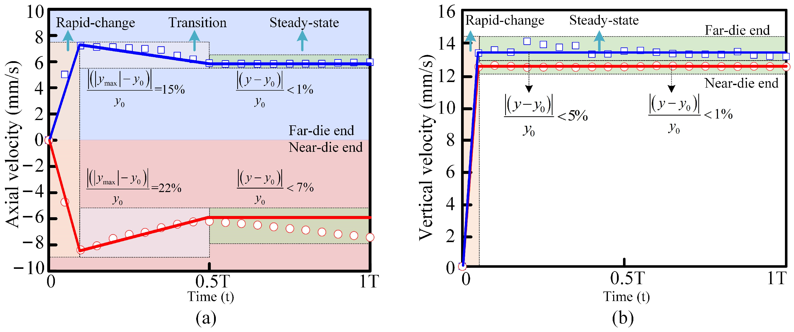
Figure 9 is derived from the deformation velocity profiles of the billet shown in Figure 7. During the initial forging stage, the axial deformation velocity of large long-shaft billets rises rapidly, then gradually decreases as strain accumulates and the flow stress evolves, eventually reaching a stable state. In contrast, the vertical deformation velocity increases sharply at the beginning but quickly transitions to a steady state without a distinct deceleration phase [19].
Based on these trends, the axial velocity distribution is divided into three characteristic stages: a rapid-change stage, a transition stage, and a steady-state stage. For the vertical velocity, two characteristic stages are identified: a rapid-change stage and a steady-state stage. In typical forging operations, the duration of a single press stroke usually ranges from 1 to 4 s [20]. Considering the relatively low deformation velocities and their clear stage characteristics, the motion coordination of the manipulators can be simplified. Therefore, for practical motion profile planning, the velocity distribution is approximated using piecewise linear fitting, as illustrated in Figure 9.
(1)
Axial Compliant Velocity
Taking the TC4 titanium alloy forging as an example, Figure 9a illustrates the simplified axial velocity curves at both ends of the workpiece during a single forging stroke. At the far-die end, the velocity rapidly increases to its peak within the initial 0.3 s of press-down motion, exhibiting an overshoot of approximately 15% relative to the steady-state value. The velocity then gradually decreases and stabilizes, with a steady-state error of less than 1%. The near-die end exhibits a similar rise time, with a velocity overshoot of approximately 22%, and stabilizes with a steady-state error of less than 7%.
Based on this observed velocity behavior, and combined with the maximum axial deformation velocities and steady-state characteristics obtained from the six representative material simulations in Table 4, simplified axial velocity profiles over time can be generated for each material. These profiles capture the variation in axial deformation velocity at both the near- and far-die ends and reflect their relationship with press parameters.
Accordingly, the axial deformation velocity at the near-die end—corresponding to the horizontal compliant velocity of the near-die gripper of the dual forging manipulators—can be expressed by the following curve function (derived using values from Table 4):
V c , H ( t ) = η c i , H , max V p t 0 t t i V max 0 . 5 T η c i , H t i V max η c i , H , max 0.5 T t i V max ( t t i V max ) + η c i , H , max V p t i V max t i V max t 0.5 T η c i , H V c t 0.5 T t T
where ηci,H (i = 1, 2, 3 … 6) is the percentage of the deformation rate of the near end of six typical forgings in the horizontal direction to the pressing rate of the press, ηci,H,max (i = 1, 2, 3 … 6) is the percentage of the maximum speed of the six typical forgings near the anvil in the horizontal direction to the pressing rate of the press, tiVmax (i = 1, 2, 3 … 6) is the time when the horizontal deformation speed of six typical forgings is the largest, T is the forging cycle time, and Vp is the press down velocity.
(2)
Vertical Compliant Velocity
As illustrated in Figure 9b, the simplified vertical deformation velocity curves of the TC4 titanium alloy forging show that both ends reach their peak velocity within approximately 0.3 s—the same as observed in the axial direction. After the initial surge, the velocities stabilize, with the steady-state error at the near-die end being less than 1%, and slightly larger at the far-die end, remaining below 5%.
The calculation method for the simplified vertical velocity curves for the six representative materials follows the same procedure as used for the axial direction. Based on the steady-state velocity values listed in Table 4 and the press stroke speed, the vertical deformation velocity profiles can be approximated.
Accordingly, the vertical deformation velocity at the near-die end—corresponding to the vertical compliant velocity of the near-die gripper in the dual forging manipulator system—can be expressed by the following curve function:
V c , V ( t ) = η c i , V V p t 0 t t st η c i , V V p t st t T
where tst is the time corresponding to the speed stability.
(3)
Axial Compliant Displacement
During the forging process, long-shaft components primarily undergo deformation along the axial direction. Due to their geometric characteristics, deformation stress is effectively relieved toward both ends, resulting in relatively uniform plastic flow at the extremities [21]. As shown in Figure 8b, the axial displacement at the near-die end accounts for approximately 27.35% of the total press stroke, while at the far-die end it accounts for about 26.95%. The displacement at both ends exhibits a nearly linear relationship with the press displacement.
The method for calculating the axial displacement curves for the six representative materials is consistent with the velocity-based approach described earlier. Based on the simulated displacement ratios relative to the total press stroke provided in the simulation data table, the axial displacement curves over time can be approximated.
Accordingly, the horizontal deformation of the forging—corresponding to the compliant displacement motion profile of the dual forging manipulators—can be expressed as:
X H ( t ) = μ c i , H t N e a r - d i e   e n d μ f i , H t F a r - d i e   e n d 0 t T
(4)
Vertical Compliant Displacement
According to the principle of cross-sectional symmetry, the theoretical vertical displacement at the center of the forging should be equal to half of the total press stroke. As shown in Figure 8a, during a single forging stroke of the TC4 titanium alloy, the vertical displacement at the near-die end is 49.85% of the press stroke, while that at the far-die end is 53.54%. These values are generally consistent with the expected symmetry and support the assumption that the vertical displacements at both ends can be approximated as 50% of the press stroke.
For all six representative large long-shaft forgings, the vertical displacement increases proportionally with time. Based on the cross-sectional symmetry principle, the vertical deformation at both ends can be reasonably approximated as 50% of the press stroke. Alternatively, the exact displacement values can be calculated using the simulation data tables for improved accuracy.
Accordingly, the vertical deformation of the forging—corresponding to the compliant displacement of the grippers in the vertical direction—can be expressed as:
X V ( t ) = μ c i , V t N e a r - d i e   e n d μ f i , V t F a r - d i e   e n d 0 t T
Based on the above analysis, it can be concluded that the deformation velocities and displacements at both ends of large long-shaft forgings are approximately equal in trend and magnitude. Therefore, the compliant motion strategy for the dual forging manipulators should adopt the bilateral compliance mode (Mode M3) as shown in Figure 4.
The specific compliant velocities and displacements of the grippers can be determined using the aforementioned analytical expressions. These results provide a theoretical basis for the subsequent analysis of the gripper actuation implementation, motion timing planning, and the development of the overall coordinated motion pattern for the dual forging manipulator system.

3.3. Manipulator Motion Planning

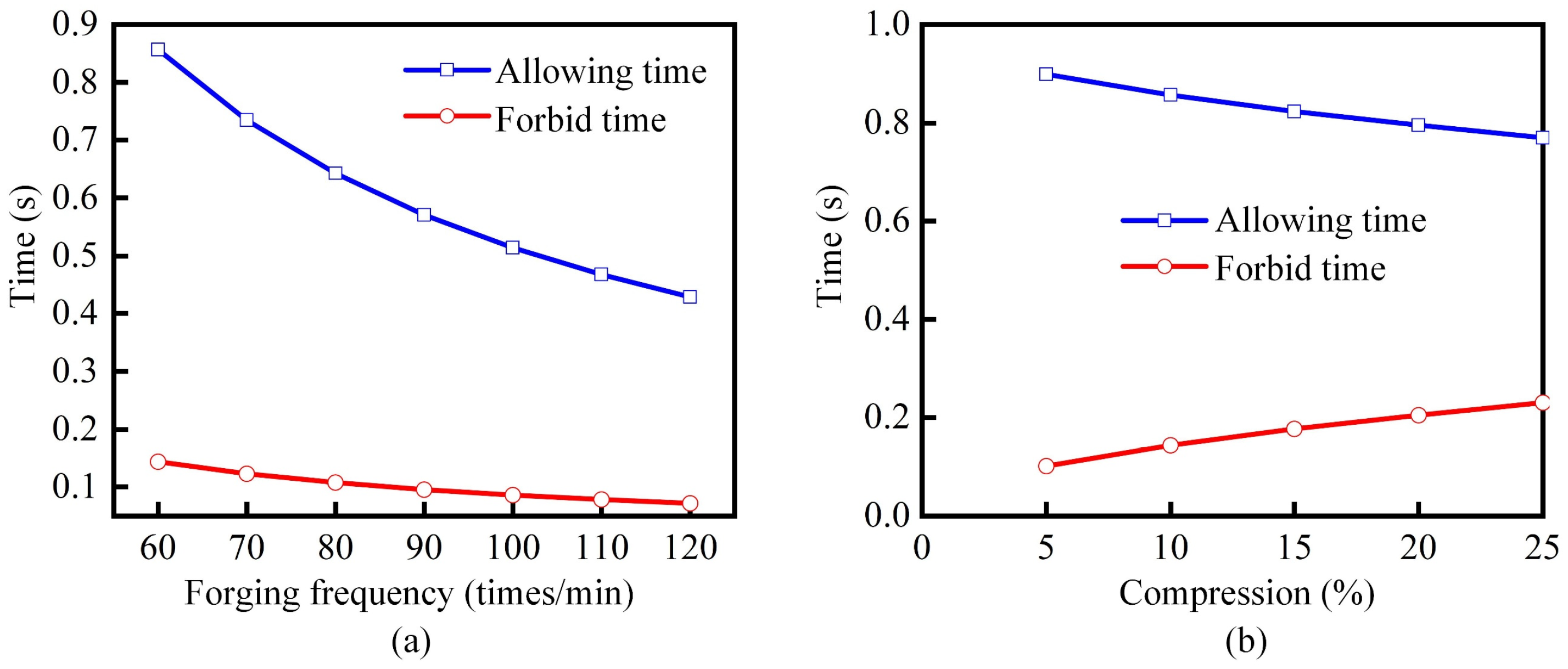
Based on the calculation methods defined in Equations (4) and (5), the allowable motion time of the forging manipulators was evaluated under different forging frequencies and press stroke conditions. When the forging frequency is 60 strokes per minute and the stroke depth is 5% of the total press range, the allowable motion time is calculated to be 0.85 s, which represents a 112.5% increase compared to traditional empirical estimates. At a higher forging frequency of 90 strokes per minute, the allowable motion time decreases to 0.571 s, marking a 90.33% improvement over empirical values.
As shown in Figure 10a, for forging frequencies ranging from 60 to 120 strokes per minute, both the allowable motion time and the forbidden motion time decrease with increasing frequency. However, the allowable motion time exhibits higher sensitivity to changes in frequency compared to the forbidden time. When the press stroke per forging cycle increases from 5% to 25%, its influence on the manipulator motion time is illustrated in Figure 10b. The total manipulator motion time tends to decrease with increasing press displacement. Specifically, the allowable motion time decreases, while the forbidden time increases. Compared to forging frequency, the stroke depth has a relatively smaller impact on the allowable motion window of the manipulator.
Once the allowable and forbidden motion periods of the manipulator within a single forging cycle are determined, the corresponding manipulator actions during each period can be clearly defined. During the allowable motion period, the manipulator can perform active operations such as trolley movement and gripper rotation. In contrast, during the forbidden motion period, which corresponds to the deformation stage of the forging, the manipulator is restricted to passive compliant motions in response to workpiece deformation—namely, horizontal buffering and vertical compliance.
Accordingly, the typical manipulator motion cycle proceeds as follows: after the initial deformation of the forging begins, both manipulators perform compliant motions simultaneously. Horizontal compliance is achieved through the buffering system, while vertical compliance is achieved by downward movement of the grippers. Once the first deformation is complete, the horizontal buffering system resets, the grippers ascend, and the system proceeds to perform gripper rotation and trolley movement operations.
To enhance forging efficiency and reduce the complexity of the manipulator hydraulic system, the gripper ascent, rotation, and trolley movement must be performed simultaneously, provided that they do not interfere with the upper and lower dies of the press. As illustrated in Figure 11, the positional relationship between the press upper die displacement curve and two different gripper ascent curves is shown. In the figure, curve L represents the vertical motion of the upper die, while curves a and b denote two non-interfering gripper ascent trajectories. t2 is the end time of the first forging deformation; t3 is the start time of the second forging deformation; tei (i = 1, 2) is the initiation time of each gripper ascent curve; and twi (i = 1, 2) is the corresponding initiation time of trolley movement for each ascent motion profile.
As shown in Figure 11, to prevent interference between the gripper and the press upper die during the ascent phase, the gripper’s upward motion profile must always remain below the position curve of the upper die. Two non-interfering ascent strategies are available under this constraint: Curve a represents a strategy where the gripper begins ascending immediately after the upper die separates from the forging. Since the press slide initially retracts at a low speed after holding pressure on the forging, the gripper must also ascend slowly to avoid exceeding the die’s vertical position and thus prevent interference. Curve b represents a delayed ascent strategy, where the gripper waits until the upper die has moved sufficiently far from the forging before initiating its ascent. In this case, the gripper can ascend at a faster rate. However, this approach may negatively affect the forming quality due to the high temperature, large mass, and low stiffness of the forging, especially if it is unsupported for too long. In practical production, the selection between these two ascent strategies can be made based on the forging material properties, process parameters, and quality requirements.
After the completion of a forging stroke, the workpiece typically forms a stepped surface in contact with the lower die. Additionally, the cross-sectional shape of the forging varies depending on the process. If the gripper performs a rotation operation while still in the low position, it may collide with the die surface. Therefore, the gripper rotation must be executed only after the gripper has ascended to a safe height to avoid such interference. Figure 12 illustrates the distribution of manipulator actions across the allowable and forbidden motion intervals under high-speed forging conditions. It clearly identifies the time windows during which each manipulator operation—such as ascent, rotation, and travel—can be safely and effectively performed.

3.4. Dynamic Characterization Test of Dual-Manipulator Forging System

Based on the previously derived compliant velocity and displacement requirements for the dual manipulators, as well as the coordinated timing between the manipulators and the press, the dynamic characteristics of the dual forging manipulators during feeding and compliance operations were experimentally verified.

3.4.1. Test Bench Configuration

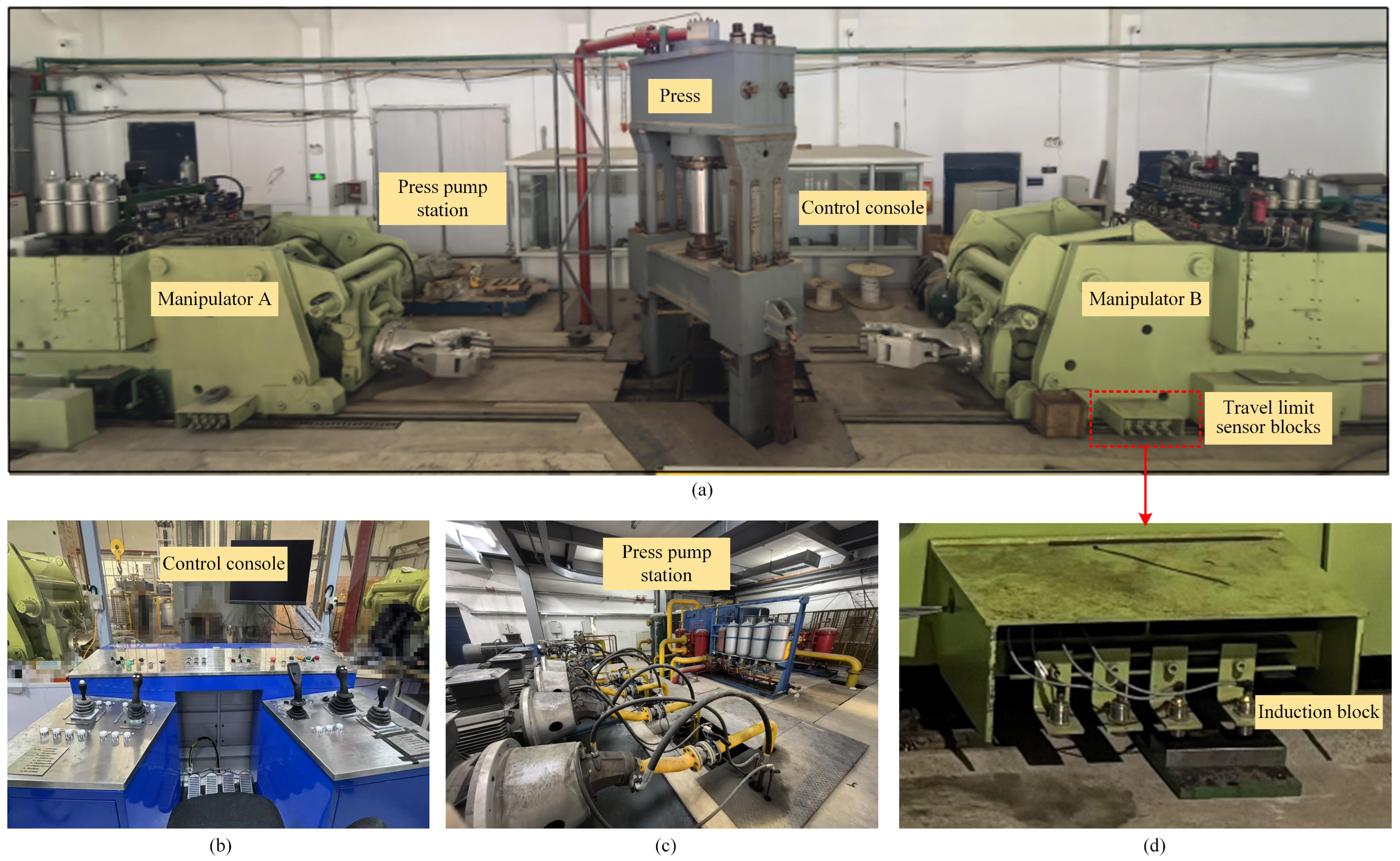
The experimental test platform is shown in Figure 13. This pilot-scale platform adopts a three-layer control architecture, consisting of the monitoring layer, control layer, and equipment layer: (1) The monitoring layer is responsible for real-time observation of operating parameters across all directions for both manipulators and the press, as well as for tracking the current operational status of the system. (2) The control layer, which forms the core of the control architecture, processes and analyzes the data transmitted from the monitoring layer in real time and issues control commands accordingly. (3) The equipment layer includes the two forging manipulators, the press, and various sensors. This layer operates under the command of the control layer. The platform integrates both electrical and hydraulic systems for motion control, and it supports manual, semi-automatic, and fully automatic operating modes. The system controller is based on the Siemens S7-300 PLC framework, which has been configured and programmed to manage the overall coordination and sequencing of operations.

3.4.2. Synchronized Trolley Feed Test of Dual Manipulators

On the pilot-scale platform, three travel limit sensor blocks were installed alongside the manipulator rails, as shown in Figure 13d, to control the trolley motion. These limit blocks were fixed to the ground using anchor bolts and placed at 500 mm, 1000 mm, and 2000 mm positions along the rail. The trolley displacement was measured using a rotary encoder mounted on the hydraulic motor. During testing, the system pressure was set to 20 MPa, and the motor opening was limited to 20%.
Figure 14 presents the displacement curve of Manipulator A during a single feeding motion, along with the corresponding proportional valve opening and motor pressure curves. It can be observed that the positioning accuracy using limit switch-based positioning is within 11 mm. The repeat positioning error was measured as 1.25 mm at 500 mm and 0.84 mm at 1000 mm, meeting the accuracy requirements for aligning the forging with the press during the pre-forging preparation stage.
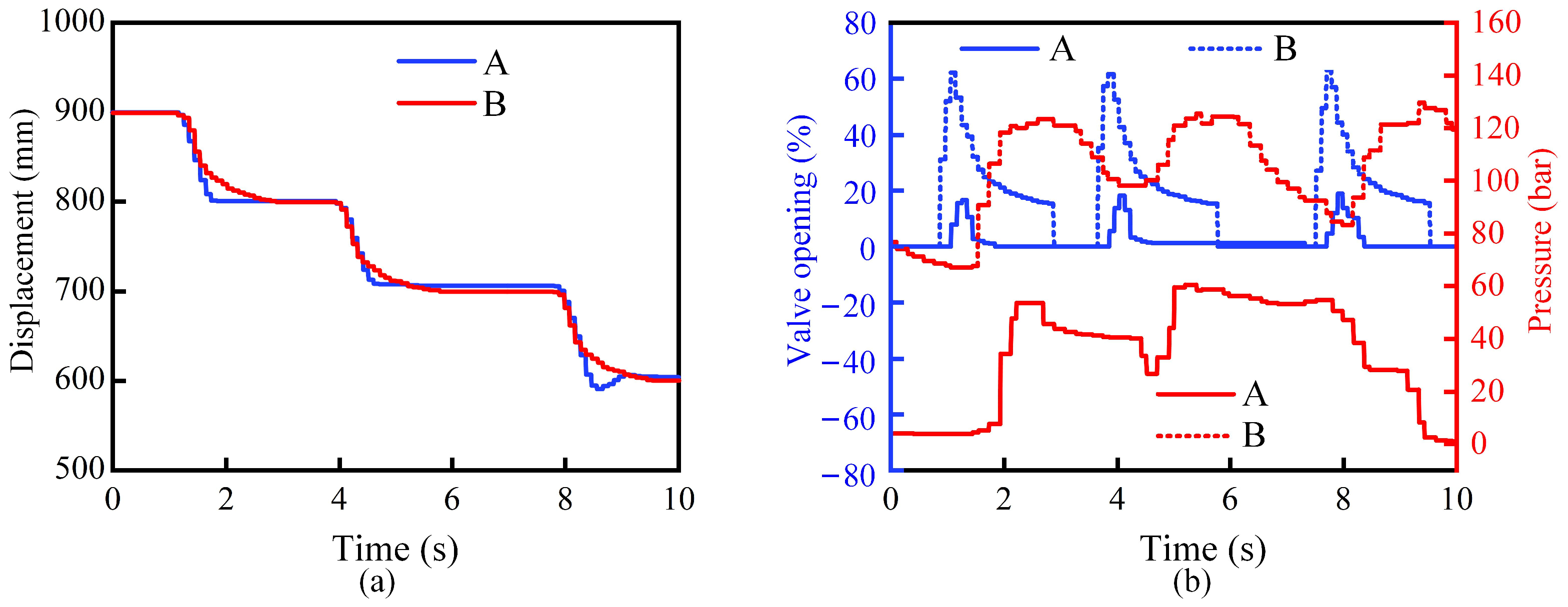
To validate dual-machine collaborative operation, a synchronous feeding test was performed, with Manipulator A moving forward, while Manipulator B moved backward. The results are shown in Figure 15. Figure 15a displays the absolute displacement curves of both manipulators during a single synchronous movement. Figure 15b shows the relationship between the control signal and the motor port pressure for Manipulator A. It was found that the response time of Manipulator A was 0.2 s, and that of Manipulator B was 0.8 s. The maximum displacement error between the two manipulators during the synchronous feed was less than 10 mm.
Figure 16a shows the absolute displacement curves for three consecutive synchronous feed actions of 100 mm each. Figure 16b presents the valve opening versus motor pressure relationship during continuous feeding. Results indicate that the position error during continuous feeding remained below 8 mm. An overshoot of approximately 15 mm was observed in Manipulator A. Nevertheless, the trolley travel synchronization between the two manipulators was deemed acceptable for coordinated operation requirements.

3.4.3. Synchronized Lifting and Gripper Rotation Tests of Dual Manipulators

An experimental evaluation was conducted to assess the lifting performance of the suspension system on Manipulator A. As shown in Figure 17, the displacement curve of the gripper during the vertical lifting motion indicates that the lowering process over a long travel range exhibits velocity fluctuations of approximately 5 mm/s. This level of fluctuation is acceptable and meets the positioning performance requirements during the pre-forging preparation phase.
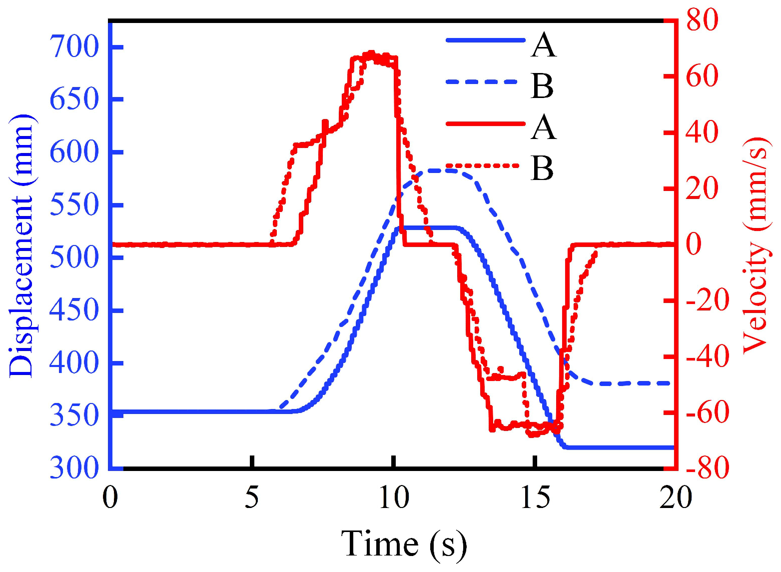
To verify dual-manipulator synchronized vertical motion, a manual control test was conducted with the system pressure set to 20 MPa. The velocity and displacement curves of the dual suspension systems during the synchronized lifting operation are shown in Figure 18. The results indicate that manual control leads to significant motion deviation, with a position error of approximately 50 mm between the two manipulators. Such error is insufficient for precise synchronization. Additionally, the lifting speed of Manipulator B shows a step-like profile, which could negatively impact the quality of the hot, flexible forging due to uneven support.
A further test was conducted to evaluate the synchronized rotational performance of the dual grippers. The maximum control signal for the proportional valve of the gripper rotation motor was set to 50%. As shown in Figure 19, the rotational synchronization between the two grippers was well maintained. During the rotation process, the maximum angular deviation between the two grippers was less than 5°, and the final angular error after the motion was completed was less than 1°. The rotation response time was approximately 1.2 s. Increasing the proportional valve control signal is expected to further improve the rotation speed, enabling the system to meet the requirements for synchronous gripping and rotation of the forging.

3.5. Operational Mode of Dual Forging Manipulators

During the forging process, the dual forging manipulators perform two primary types of actions: feeding and compliance. The feeding actions occur during the intervals between forging strokes and are used to adjust the relative position between the forging and the press. These are achieved through trolley motion (for horizontal positioning), lifting cylinder actuation in the suspension system (for vertical positioning), and gripper rotation (for adjusting the forging’s circumferential orientation). The compliant actions are designed to ensure operational safety and maintain forging quality. These include trolley retreat and buffering movements in response to the forging’s deformation behavior during the press stroke.
This study focuses on the forging sequence of elongation (drawing) for large long-shaft forgings clamped by dual manipulators. The coordinated motion pattern for the dual forging manipulators under this process is summarized in Table 5 and described as follows:
(1)
Pre-Forging Adjustment Stage
The position of the forging is pre-adjusted using auxiliary equipment. Both manipulators then simultaneously clamp the forging and adjust its position relative to the press via synchronized trolley motion and synchronized vertical lifting by the suspension systems. During this stage, both manipulators are permitted to execute arbitrary motions as needed to prepare for the initial forging stroke.
(2)
Inter-Pass Compliance Stage
Based on the forging material, the corresponding deformation data are retrieved from the pre-established forging deformation database. These are correlated with the press parameters to determine the deformation velocity and displacement at both ends of the forging. The manipulators then execute compliant actions in both vertical and horizontal directions: in the horizontal direction, Manipulator A performs active compliance via its buffering cylinder, while Manipulator B performs passive compliance, driven by the forging’s reaction force. Both displacement and velocity signals can be used as control inputs. Specific compliance methods are detailed in Section 3.2. In the vertical direction, compliance is achieved via proportional throttle control, utilizing the gripper’s structural support and the forging’s self-weight. The displacement command is set to 50% of the press stroke, consistent with deformation symmetry.
(3)
Execution Stage
This stage is constrained within the allowable motion time window of the manipulators. The sequence begins with gripper ascent, followed by gripper rotation and trolley motion, which are executed in parallel based on the selected ascent motion profile. The start and end times of each action are determined by the gripper ascent curve. Detailed timing and motion sequences are provided in Section 3.3.
(4)
Forging Completion Stage
Based on the forming process requirements, multiple cycles of the inter-pass compliance stage and execution stage are repeated until the desired forging specifications are achieved. This marks the completion of a full forging task cycle.

4. Conclusions

By systematically summarizing the characteristics of typical industrial long-shaft billets and analyzing their deformation behaviors, this study establishes a coordination framework for dual manipulators and a hydraulic press throughout the forging cycle. This framework enables the manipulators to collaboratively grip and manipulate the billet, facilitating complex forging operations and laying the groundwork for high-precision forging tasks. Building on this foundation, future research will integrate advanced algorithms and nonlinear system considerations to develop a precise motion profile planning method. This method will enable cooperative control of the dual manipulators and the press, accounting for dynamic deformation resistance, motion coupling, and multi-parameter interactions, ultimately improving the efficiency and accuracy of dual-manipulator forging systems. The relevant research results are as follows:
(1)
Based on industry requirements and the characteristics of the forging process, the properties of typical shaft-type forgings were systematically classified. Six representative material models were developed by considering key parameters such as Young’s modulus, Poisson’s ratio, and forging temperature. Finite element simulations using DEFORM-3D (V11.0) were performed to analyze the deformation behaviors at both ends of the forgings under single-stroke loading. From these simulations, characteristic velocity and displacement profiles were extracted, along with their response relationships to key press parameters for each material.
(2)
A three-phase segmentation method was proposed to describe the end-deformation velocity curves of the forgings, consisting of a rapid-change zone, a transition zone, and a steady-state zone. By coupling these deformation characteristics with press motion parameters, a compliant motion demand model for dual forging manipulators was established. This model lays the theoretical foundation for accurate motion profile planning and velocity control of the manipulators.
(3)
A segmented timing model was developed based on the downward stroke profile of the press, enabling the reconstruction and optimization of the manipulators’ allowable motion windows. Under typical forging conditions (5% press stroke depth with forging frequencies of 60 and 30 strokes per minute), the allowable motion time was improved by 112.5% and 42.85%, respectively, demonstrating the method’s effectiveness in enhancing the timing coordination between the press and manipulators.
(4)
Experimental validation was performed on a dual-manipulator system to evaluate its dynamic response and confirm the feasibility of the compliant motion strategy. By analyzing the sequence, timing, and functional phases of manipulator actions, a four-phase coordinated motion pattern—pre-forging adjustment, inter-pass compliance, execution phase, and forging completion—was summarized. This framework provides not only a practical reference for the coordinated control of dual manipulators but also a theoretical basis for advancing intelligent, high-precision forging operations.

Author Contributions

Conceptualization, F.Z. and Y.X.; methodology, Y.X. and R.C.; software, Y.W.; validation, Y.X., J.S. and X.H.; formal analysis, R.C. and J.S.; investigation, Y.X.; data curation, R.C.; writing—original draft preparation, Y.W. and Z.W.; writing—review and editing, Y.X. and Z.W.; project administration, F.Z. All authors have read and agreed to the published version of the manuscript.

Funding

This research was funded by the National Natural Science Foundation (Grant No. 52175064); National Science and Technology Major Project (Grant No. 12124778012).

Data Availability Statement

Data are contained within the article.

Conflicts of Interest

Authors Junqiang Shi and Zhuo Wang were employed by the company Beijing Research Institute of Automation for Machinery Industry Co., Ltd. The remaining authors declare that the research was conducted in the absence of any commercial or financial relationships that could be construed as a potential conflict of interest.

References

  1. Li, G.; Sun, W.; Liu, D. Investigation of the dynamic bending moment transmitted to the forging manipulator due to press motion. J. Mech. Sci. Technol. 2013, 27, 2435–2443. [Google Scholar] [CrossRef]
  2. He, X. Effects of manipulator compliant movements on the quality of free forgings based on FEM simulation. Int. J. Adv. Manuf. Technol. 2011, 56, 905–913. [Google Scholar] [CrossRef]
  3. Ding, W.H.; Deng, H.; Zhang, Y.; Ren, Y.Q. Optimum design of the jaw clamping mechanism of forging manipulators based on force transmissibility. Appl. Mech. Mater. 2012, 157, 737–742. [Google Scholar] [CrossRef]
  4. Cao, X.; Yao, J.; Sha, T.; Song, Y. Pressure-Relief Impact Control of Open Circuit Hydraulic Pump-Controlled Forging Press System. Processes 2019, 7, 638. [Google Scholar] [CrossRef]
  5. Zhang, Y.; Ding, W.; Deng, H. Reduced dynamic modeling for heavy-duty hydraulic manipulators with multi-closed-loop mechanisms. IEEE Access 2020, 8, 101708–101720. [Google Scholar] [CrossRef]
  6. He, Z.; Zhai, F.; Xing, Y.; Wang, X.; Zhao, R.; Chang, R. Research on the perception capability and characteristics based on the full-attitude indirect sensing model of forging force. Mech. Based Des. Struct. Mach. 2025, 53, 5513–5533. [Google Scholar] [CrossRef]
  7. Xing, Y.; Zhai, F.; He, Z.; Wang, X.; Zhao, R. Enhanced Force Sensing Method Using BP Neural Network and Sensitive Point Analysis for Forging Manipulator Clamping Mechanism in Operational Conditions. Machines 2025, 13, 226. [Google Scholar] [CrossRef]
  8. Wang, G.; Li, X.; Ding, M.; Chen, W.; Tian, C.; Gu, G.; Lu, Y. Study on deformation uniformity of mandrel forging process and control measures of inner hole eccentricity. J. Manuf. Process. 2020, 58, 75–91. [Google Scholar] [CrossRef]
  9. Cai, J.; Guo, M.; Peng, P.; Han, P.; Yang, X.; Ding, B.; Qiao, K.; Wang, K.; Wang, W. Research on hot deformation behavior of as-Forged TC17 titanium alloy. J. Mater. Eng. Perform. 2021, 30, 7259–7274. [Google Scholar] [CrossRef]
  10. Rahul, M.R.; Samal, S.; Venugopal, S.; Phanikumar, G. Experimental and finite element simulation studies on hot deformation behaviour of AlCoCrFeNi2. 1 eutectic high entropy alloy. J. Alloys Compd. 2018, 749, 1115–1127. [Google Scholar] [CrossRef]
  11. Yan, C.; Gao, F.; Guo, W. Coordinated kinematic modelling for motion planning of heavy-duty manipulators in an integrated open-die forging centre. Proc. Inst. Mech. Eng. Part B J. Eng. Manuf. 2009, 223, 1299–1313. [Google Scholar] [CrossRef]
  12. Pinto, B.A.M.B. Polylactic Acid-Based Stent Manufacturing Using Fused Deposition Modeling from a Biomedical Perspective. Master’s Thesis, Universidade do Porto, Porto, Portugal, 2019. [Google Scholar]
  13. Şimşir, C.; Duran, D. A flow stress model for steel in cold forging process range and the associated method for parameter identification. Int. J. Adv. Manuf. Technol. 2018, 94, 3795–3808. [Google Scholar] [CrossRef]
  14. Sciavicco, L.; Siciliano, B. Modelling and Control of Robot Manipulators; Springer Science & Business Media: Berlin/Heidelberg, Germany, 2012. [Google Scholar]
  15. Yao, J.; Li, Y.; Zhai, F.; Zhu, H.; Zhang, Y. Energy Dissipation Analysis of Forging Manipulator Hydraulic Systems in Stretching Processes. China Mech. Eng. 2019, 30, 385–392. [Google Scholar]
  16. Gaikwad, S.D.; Dabhade, V.V.; Murty, S.N.; Manwatkar, S. Mechanical properties and deformation mechanism at elevated temperatures of IN718 superalloy processed by powder forging. Mater. Sci. Eng. A 2025, 924, 147803. [Google Scholar] [CrossRef]
  17. Fang, X.; Liu, H.; Liu, J.; Li, H.; Yang, F. Dynamic design and application on Ti-6Al-4V of novel hybrid forging system. J. Mech. Sci. Technol. 2025, 39, 201–212. [Google Scholar] [CrossRef]
  18. Zhao, Q.; Wu, G.; Sha, W. Deformation of titanium alloy Ti–6Al–4V under dynamic compression. Comput. Mater. Sci. 2010, 50, 516–526. [Google Scholar] [CrossRef]
  19. Prabhu, T.R. Modelling studies on effects of deformation speed, preform shape, and upset ratio on the forging characteristics of the aerospace structural Al alloys. Int. J. Mater. Prod. Technol. 2017, 54, 291–305. [Google Scholar] [CrossRef]
  20. Chen, B.; Zhang, L.; Ma, H.; Lu, G. Superimposed liquid supply energy-saving technology on fast forging hydraulic press. Forg. Technol. 2023, 48, 199–203. [Google Scholar]
  21. Ma, Q.; Lin, Z.Q.; Yu, Z.Q. Prediction of deformation behavior and microstructure evolution in heavy forging by FEM. Int. J. Adv. Manuf. Technol. 2009, 40, 253–260. [Google Scholar] [CrossRef]
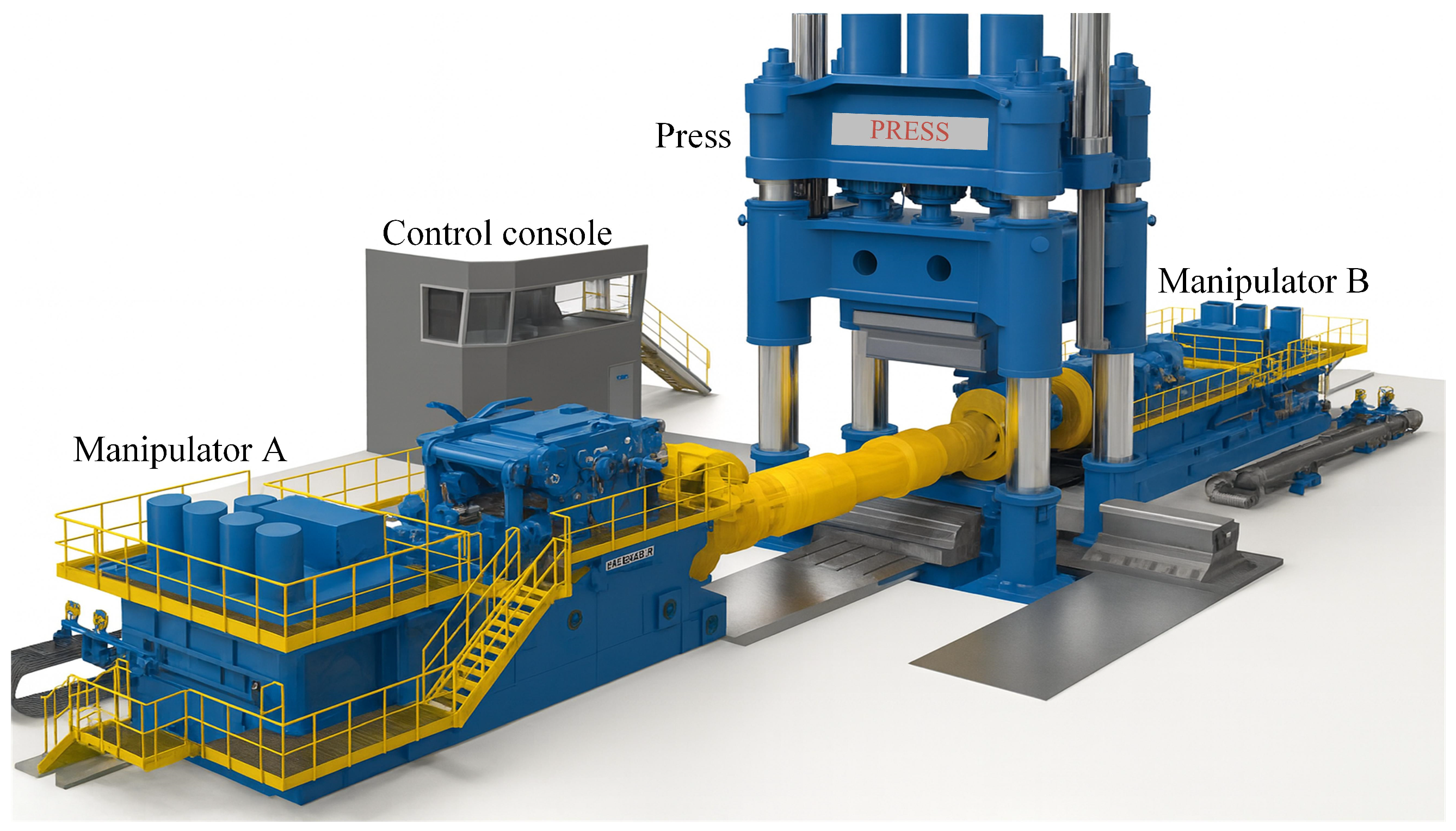
Figure 1. Dual-Manipulator Forging Mode.
Machines 13 00816 g001
Figure 2. Configuration of the Dual-Manipulator Forging System and Clamping Motion Modes.
Machines 13 00816 g002
Figure 3. Compliance Process of a Single Manipulator During One Forging Stroke.
Machines 13 00816 g003
Figure 4. Three Compliance Modes of Clamps in the Dual-Manipulator Configuration.
Machines 13 00816 g004
Figure 5. Finite Element Model of Bilateral Forging and Distribution of Observation Points.
Machines 13 00816 g005
Figure 6. Manipulator Operation Time under High-Speed Forging Conditions.
Machines 13 00816 g006
Figure 7. Deformation Velocity on Both Sides of the Titanium Alloy Forging (a) Vertical Velocity, (b) Axial Velocity, (c) lateral Velocity.
Machines 13 00816 g007
Figure 8. Deformation Displacement on Both Sides of the Titanium Alloy Forging (a) Vertical Displacement, (b) Axial Displacement, (c) lateral Displacement.
Machines 13 00816 g008
Figure 9. Deformation Velocity Curve of Long-Shaft Forging (a) Axial; (b) Vertical.
Machines 13 00816 g009
Figure 10. Variation in Manipulator Action Time: (a) Influence of Forging Frequency, (b) Influence of Pressing Stroke.
Machines 13 00816 g010
Figure 11. Manipulator Gripper Lifting Curves and Trolley Movement Start Time.
Machines 13 00816 g011
Figure 12. Motion Distribution of Forging Manipulator.
Machines 13 00816 g012
Figure 13. Experimental Setup of Dual-Manipulator System: (a) Dual Forging Manipulators and Hydraulic Press; (b) Central Control Console; (c) Hydraulic Press Pump Station; (d) Trolley Travel Limit Device of Manipulator.
Machines 13 00816 g013
Figure 14. Experimental Curves of Trolley Feed Motion for Manipulator A: (a) Displacement of Continuous Trolley Feed; (b) Valve Opening and Motor Pressure.
Machines 13 00816 g014
Figure 15. Experimental Curves of Synchronized Single Feed Motion for Dual Forging Manipulators: (a) Displacement of Single Feed for Dual Manipulators; (b) Valve Opening and Motor Pressure.
Machines 13 00816 g015
Figure 16. Experimental Curves of Synchronized Continuous Feed Motion for Dual Forging Manipulators: (a) Displacement of Continuous Feed for Dual Manipulators; (b) Valve Opening and Motor Pressure.
Machines 13 00816 g016
Figure 17. Experimental Curves of Lifting Motion of Manipulator A’s Suspension System (a) Lifting Cylinder Displacement; (b) Valve Opening of the Lifting Cylinder.
Machines 13 00816 g017
Figure 18. Experimental Curves of Manually Controlled Synchronized Lifting of Dual Forging Manipulator Suspension Systems.
Machines 13 00816 g018
Figure 19. Experimental Curves of Synchronized Gripper Rotation of Dual Forging Manipulators.
Machines 13 00816 g019
Table 1. Properties of Typical Large Long-Shaft Forgings in Various Industries.
Application FieldsMaterialsApplication RangeYoung’s Modulus (GPa)Poisson’s RatioForging Temperature (°C)
Automobiles and heavy machinery42CrMo4High load2100.28900–1100
42CrMoHigh stress2050.29900–1150
20CrMnTiShock load2000.27850–950
Aerospace34CrNiMo6High strength2100.29850–1050
GH4169High temperature2000.31980–1150
Ti-6Al-4VCorrosion resistance1140.34930–980
Energy and chemical industry15CrMoHigh temperature and high pressure2060.3900–1050
GH4169High-temperature corrosion resistance2000.31980–1150
General machinery45 steelModerate load2000.29800–1050
Medical devicesTi-6Al-4VCorrosion resistance1140.34930–980
Table 2. Categorization of Material Properties.
HighMiddleLow
Temperature (°C)800–900850–10001000–1150
Young’s modulus (Gpa)200–210150100–120
Poisson’s ratio 0.3–0.340.28–0.290.27
Table 3. Simulation Parameters of Typical Long-Shaft Forgings.
NumberYoung’s Modulus (GPa)Poisson’s RatioTemperature (°C)Material
1High (210)Middle (0.28)Middle (900)42CrMo4
2High (210)High (0.31)High (1100)GH4169
3Middle (150)Middle (0.29)Middle (900)42CrMo
4Middle (150)Low (0.27)Middle (850)20CrMnTi
5Low (120)High (0.34)Middle (950)Ti-6Al-4V
6Low (120)Middle (0.28)Low (800)45 steel
Table 4. Simulation Results of Typical Long-Shaft Forgings (unite: %).
NumberDirectionNear-Die End
Velocity
Far-Die End
Velocity
Near-Die End
Displacement
Far-Die End
Displacement
Near-Die End Maximum VelocityFar-Die End Maximum Velocity
1Horizontal28.7727.9126.6429.7635.2127.63
Vertical49.3547.4049.8353.59————
2Horizontal28.8525.1326.7126.6333.5529.56
Vertical50.0053.5249.9353.88————
3Horizontal28.7724.9426.8627.0837.2230.01
Vertical49.8051.7049.8953.44————
4Horizontal28.0826.7323.1328.4631.2228.44
Vertical49.7051.3049.9353.86————
5Horizontal29.6924.7427.3826.9536.2228.45
Vertical49.8052.3549.8553.54————
6Horizontal28.4926.1223.2628.0935.6627.98
Vertical49.4550.2049.8553.70————
Table 5. Operational Modes of Dual Forging Manipulators.
Forging ProcessManipulator ActionMotion TimePress Action
Pre-Forging Adjustment StagePitching, clamp opening and closing clamping,
clamp lifting, cart walking
Allowing time——
Inter-Pass Compliance StageHorizontal and vertical bufferingForbid timeExtrusion forging deformation
Execution StageCart walking, clamp rotation,
buffer reset
Allowing timeNo-load return Accelerated pressing
Forging Completion Stage——Allowing time——
Disclaimer/Publisher’s Note: The statements, opinions and data contained in all publications are solely those of the individual author(s) and contributor(s) and not of MDPI and/or the editor(s). MDPI and/or the editor(s) disclaim responsibility for any injury to people or property resulting from any ideas, methods, instructions or products referred to in the content.