Article

Influence of Thin-Film Coatings on the Joining Process of Shaft-Hub Connections

1
Institute for Engineering Design and Industrial Design (IKTD), University of Stuttgart, Pfaffenwaldring 9, 70569 Stuttgart, Germany
2
Institute for Surface Technology, Technische Universität Braunschweig, Riedenkamp 2, 38108 Braunschweig, Germany
3
Fraunhofer Institute for Surface Engineering and Thin Films, Riedenkamp 2, 38108 Braunschweig, Germany
*
Author to whom correspondence should be addressed.
Machines 2025, 13(9), 776; https://doi.org/10.3390/machines13090776
Submission received: 6 August 2025 / Revised: 26 August 2025 / Accepted: 28 August 2025 / Published: 29 August 2025
(This article belongs to the Section Machine Design and Theory)

Abstract

With the ongoing electrification of vehicles and the resulting demand for higher power densities, drivetrain requirements are becoming increasingly stringent. Shaft-hub connections are particularly affected in terms of both quantity and design, making innovative solutions necessary. A key factor in meeting these requirements is knowledge of the stress state within the contact area. One promising approach is the application of a thin-film-based sensor system directly onto the shaft surface. This enables, for the first time, the direct measurement of contact pressure in the interface, allowing for more precise connection design. To fully exploit the potential of this sensor technology, its influence on the joining process of shaft-hub connections must be investigated. In this study, cylindrical interference-fits were coated with two thin-film systems relevant to the application, followed by joining tests. The resulting damage was analyzed to derive general recommendations for the joining of coated shaft-hub connections. The results show that shrink-fitting enables damage-free joining, provided specific parameters are met, as confirmed by experimental testing and microscopic examination. This not only preserves the integrity of the sensor system but also establishes the prerequisite for potential in situ measurements, thereby laying the foundation for the feasibility of direct load monitoring during operation.

1. Introduction

Shaft-hub connections (SHCs) are a common machine element in drive technology, particularly in gearboxes and electric motors [1]. The cylindrical interference-fit, classified as a friction-locking SHC, is especially popular due to its simple functional principle and geometry [2]. With the increasing focus on drivetrain electrification, both the number and significance of SHCs are evolving, along with their technical requirements [3]. Key demands include space efficiency, weight reduction, and higher power density. Meeting these challenges in design and engineering requires innovative solutions [3].
The application of a thin-film-based sensor system on the shaft is an effective and practical solution, offering the potential to optimize the design and dimensioning of SHCs by measuring the contact pressure p in situ. The calculation method for the elastic design of cylindrical interference-fits is defined in the German standard DIN 7190-1 [4], which is based on Lamé’s theory. As a result, the three-dimensional stress state can be reduced to a plane stress state at the interface, allowing the integral contact pressure to be determined under the influence of the parameters external and internal Diameter D, surface roughness Rz, elastic modulus E, diameter ratio Q, and the Poisson’s ratio μ using the following, Equation (1).
p = ξ w × E h u b K = D i , h u b D a , s h a f t 0.4 × R z h u b + R z s h a f t × E h u b E h u b E s h a f t × 1   +   Q s h a f t 2 1     Q s h a f t 2 μ s h a f t + 1   +   Q h u b 2 1     Q h u b 2 + μ h u b
However, local stress concentrations are neglected in the region of the hub edges, which arise from stiffness discontinuities caused by the shaft protruding from the hub. Alternative methods, such as simulations or experimental approaches, also only provide approximate values for the contact pressure [5].
The sensor-integrated thin-film system addresses this limitation by enabling the first direct measurement of the actual pressure distribution. This significantly reduces uncertainties and deviations in the design process, for example, in the calculation of the transmittable torque T according to Equation (2). The calculation is based on the joint length lF, joint diameter DF, the safety factor against slipping Sr, and static coefficient of friction (COF) for slipping νr.
T = π 2 × D F 2 × l F × ν r × p S r
By knowing the actual load condition, the transferable torque can be accurately calculated. This creates the opportunity to use lower safety factors, potentially reducing the need of over-dimensioning. As a result, a more compact design and weight savings in SHCs across all applications can be achieved.
Measurement using thin-film sensors in the contact zone requires a damage-free and stable joining process. Two different joining methods for SHCs are available: In press-fits, the shaft and hub are assembled by applying a high axial force using a mechanical or hydraulic press. In contrast, a shrink-fit is formed by exploiting thermal expansion [1]. The resulting difference between the inner diameter of the hub and the outer diameter of the shaft, which enables the joining process, is referred to as the joining clearance. This research focuses on the experimental investigation of the influence of coatings on the joining behavior of SHCs, with the aim of showing the feasibility and providing general design recommendations for the joining process. A stable and damage-free joining process is key to enabling subsequent measurements.

2. Definitions

This chapter provides the essential background for the experimental investigations. Section 2.1 describes the thin-film systems applied to the shafts, which serves as the basis for contact pressure measurement. Following this, Section 2.2 discusses the specimen geometry, followed by an explanation of the joining devices required for assembling the shaft and hub into an SHC in Section 2.3.

2.1. Thin-Film Sensor System

Due to its intended application, the thin-film system consists of three layers with a total thickness of approximately 6 μm. The structure and materials of the layers have been specifically developed for contact pressure measurement in interference-fits, based on the established requirements. Each layer has distinct mechanical or electrical properties and functions, all of which are essential for the overall system’s performance. The complete thin-film system is shown in Figure 1.
The layers are deposited on the substrate A using chemical and physical vapor deposition processes. The first layer (I) serves as an electrical insulation layer between the metallic substrate and the metallic sensor layer II. This layer is an aluminum oxide (Al2O3) coating with a thickness of approximately 3–4 μm. Al2O3 is commonly used in tribological thin-film sensor applications due to its combination of good insulation properties as well as a high hardness [9]. The sensor layer II, a photolithographically structured metal or metal alloy layer with a thickness of approximately 0.2 μm is applied according to the measured variable. Conductor paths will also be structured within this layer. The piezoelectric effect is used in order to measure the contact pressure, i.e., the electrical resistance changes linearly with applied pressure. Since temperature change is also affecting the resistance (thermoresistive effect), the material for the pressure sensor should have a comparably high ratio of pressure to temperature coefficient. To correct for the remaining temperature influence, an additional temperature sensor of a different material is used [10]. In contrast to the pressure sensor, this sensor should have a low ratio of pressure to temperature coefficient. The investigated materials are manganin and chromium as pressure sensors and titanium as a temperature sensor.
The system is completed with an electrical insulation and wear protection layer III, made of either Al2O3 or SICON®, with a thickness of 2.5–3.5 μm. The electrical insulation is essential due to the contact to the metallic hub. The SICON® layer is an amorphous hydrocarbon coating modified with silicon and oxygen (a-C:H:Si:O) developed at Fraunhofer IST, which can be classified as a DLC coating [11]. DLC layers exhibit relatively high hardness due to the carbon being present in both graphite and diamond bonding forms. Doping with silicon and oxygen modifies the electrical and chemical properties of the layer allowing it to be applied as an electrical insulation layer in tribologically loaded thin-film sensor systems [12].
The selection of suitable thin-film systems for contact pressure measurement in interference-fits can only be made through experimental investigations. Therefore, both thin-film systems are examined in this publication. Since no measurements are conducted in this study, the sensor layer is applied without any structuring.

2.2. Specimen Geometry

The specimen geometry remains unchanged for all experimental investigations described. In determining the specimen geometry, factors such as comparability with other tests at the research facility, connection dimensions and conditions relative to the joining devices, the maximum dimensions imposed by the coating devices, coating requirements for the substrate (shaft) and contact body (hub) derived from previous projects, and the proximity to industrial application areas were considered. The specimen geometry and dimensions are shown in Figure 2.
The thin-film system is only applied to the shaft because coating the inner hub surface is currently not possible with the available coating devices due to inaccessibility [5]. The shaft material is hardened to its maximum hardness to minimize the risk of the so-called eggshell effect. This implies that localized overloads lead to excessive point-specific tensile stress in both the coating and the underlying material. In contrast, the hub material is deliberately chosen to be as soft as possible. It is expected that this allows any detached coating particles to be potentially absorbed into the hub material. Due to soft annealing, joining temperatures remain too low to affect the microstructure. The chamfer design follows the minimum requirements of DIN 7190-1 [4] for press-fits, ensuring a simple geometry with minimal space requirements. The selected interference ξ of 1.7‰, which can be calculated with the geometric interference lgeo and the joint diameter DF according to Equation (3)
ξ = l geo D F · 1000   [ ]
is industry-relevant and provides a high measurement resolution of the sensor system by generating a contact pressure of approximately 130 MPa calculated with Equation (1). The thin-film system is accounted for by including its thickness in the shaft diameter. Apart from this increase in diameter, the coating does not have any additional effect on the contact pressure.
Since no measured values are required for the joining tests and integrating the sensor technology involves significant effort and high costs for calibration and measurement, the sensor layer is not structured but applied over the entire surface. To evaluate the material properties of the layers and their interaction within the overall composite for all sensor types—while minimizing the number of specimens—the sensor layer is varied in four sections in the contact area of the specimen to accommodate different material variants (manganin, chromium, titanium, and no sensor layer). Since the results are mostly consistent across all materials used for the second layer, all figures shown in this contribution display chromium as the sensor material. In total, two specimens with identical geometry but different wear-protection layers are available. In the following they are referred to by the type of the two applied coating as: Al2O3-specimen and SICON®-specimen.

2.3. Joining Devices

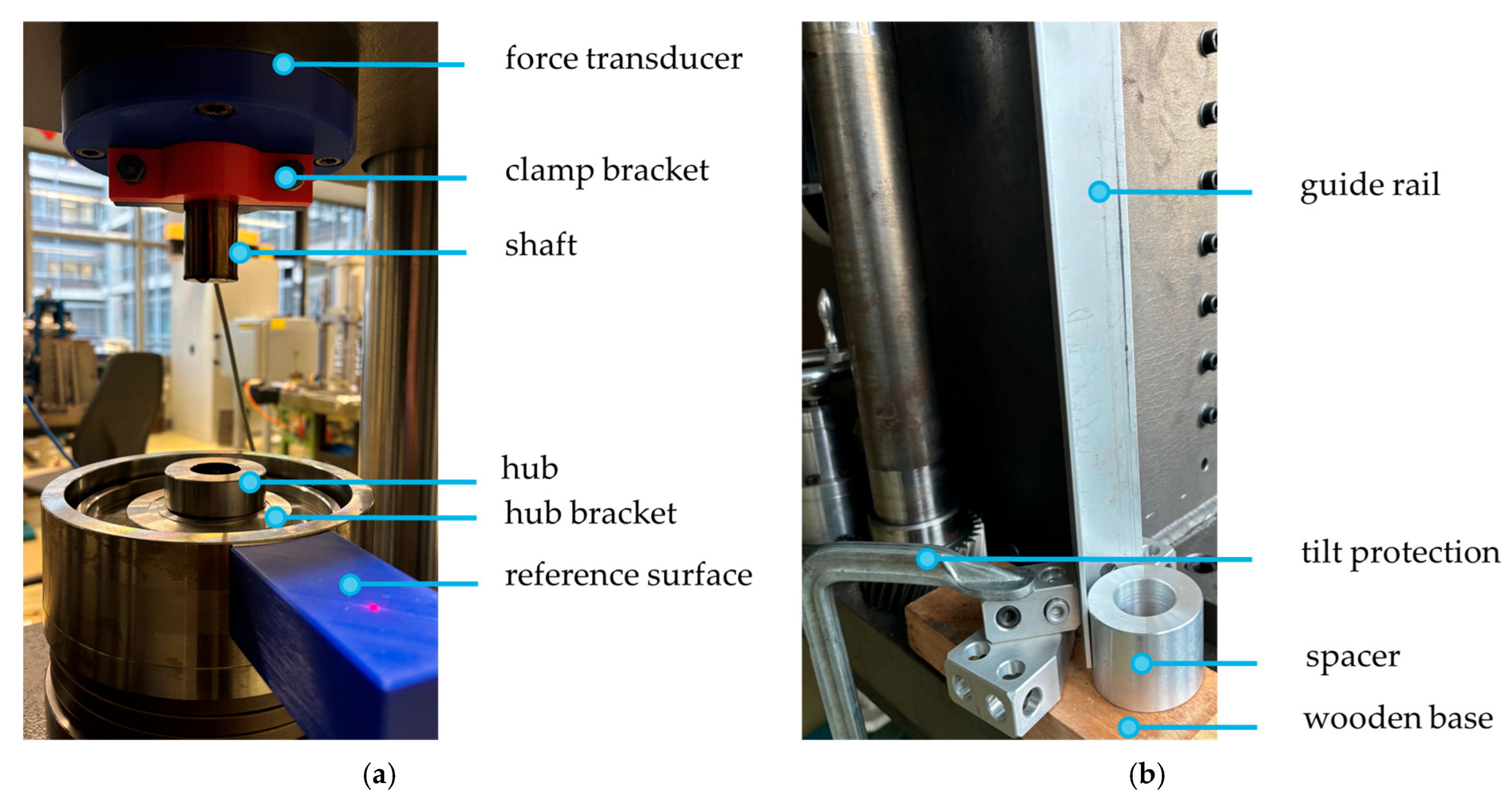
A dedicated device was developed for each joining process based on existing designs, as shown in Figure 3.
A hydraulic press is used for joining press-fits. The shaft is mounted on the upper part of the press using an adapter designed as a clamp bracket, ensuring the shaft is guided and prevented from tilting. The hub is placed on the hub bracket in the lower part of the press. During the joining process a laser sensor records the displacement and a force transducer monitors the force to capture a force-displacement curve.
During the shrink-fitting process, the shaft is cooled and the hub is heated due to high interference. The devices available for cooling, along with their respective temperature ranges, are shown in Table 1. For heating the hub, a furnace is used, which allows precise temperature control and maintenance in the range of 0–650 °C.
The cooling of the shaft is limited to −195.8 °C for technical reasons, while the maximum temperature of the hub is constrained by structural changes that occur once the tempering temperature is reached, depending on the material. In contrast to cooling of the shaft, heating in the furnace allows the hub temperature to be adjusted continuously. Once the individual components have reached the required temperature, the joining process begins with the joining device shown in Figure 3. The shaft, with the chamfer facing upwards, is inserted into the hole of the spacer, which is then pushed with its outer surface against the guide rail. This centers the shaft relative to the guide rail. The spacer is placed on a wooden board to slow the heating of the shaft to ambient temperature, due to the relatively low thermal conductivity of the material. The guide rail is attached to the table via a bracket which acts as a tilt protection. For joining, the heated hub is pressed against the guide rail along the entire height of its lateral surface and moved downward in a centered position until the bottom side of the hub rests flat on the spacer.

3. Test Approach

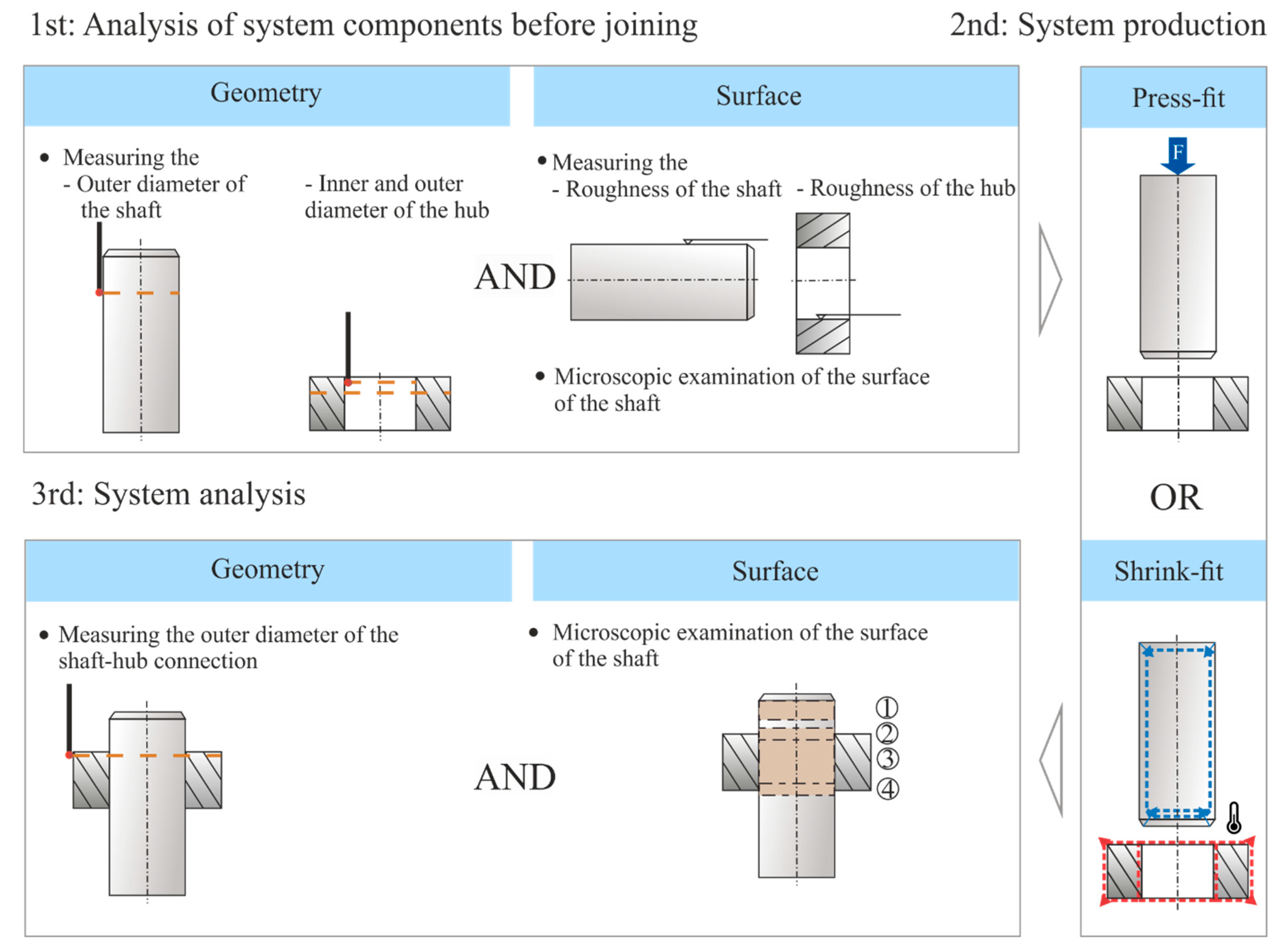
To achieve the previously described objectives, experimental investigations are conducted on the two thin-film systems described above. The procedure is outlined below. The investigative approach is divided into three parts: analysis of the individual components, system production, and system analysis, as shown in Figure 4 for an overview.
The first step involves the separate analysis of the components (hubs and coated shafts). This analysis includes the specific measurement of all individual components, random measurement of the surface roughness of the respective contact surfaces, as well as a microscopic examination of the coating. Defined measurement principles are applied in advance for both analyses. The coated shafts and hubs are measured on a Zeiss Prismo coordinate measuring machine, where the outer diameter of the coated shafts and both the inner and outer diameters of the hub and their cylindricity are measured. Manufacturing tolerances cause deviations between actual and nominal values. To ensure the most consistent interference-fit across all specimen, shafts and hubs are carefully matched based on these measurements. Additionally, the outer diameter of the hub is required for a later step to evaluate the hub’s expansion. The outer diameter of the shaft is measured in the planned contact area using 19 circular paths spaced one millimeter apart, with 360 points per circular path. The first circular path is measured one millimeter below the potential hub edge. The same measurement principle is applied to determine the inner and outer diameters of the hub. The required accuracy of the measurements is ensured by the small distance between the circular paths and the high number of points per circular path. To match the shaft and hub, the average value of the respective measurements is determined, and the individual components are allocated in such a way that the interference is as consistent as possible and close to the demanded interference. A calculation of the effective interference, taking into account the surface roughness of the individual components, is not required due to the low surface roughness tolerance. Furthermore, for specimens to be joined as shrink-fits, the joint clearance must be checked analytically according to DIN 7190-1 [4], considering the extreme values (max. outer diameter of the shaft and min. inner diameter of the hub). Compliance with the required surface roughness of the individual components is randomly checked using a tactile surface measuring device from Hommel. In microscopic examinations with a digital light microscope (Keyence VHX 7000), the complete coating is analyzed for any defects caused during the coating process. All defects are documented so they can be later distinguished from damage caused by the joining process after the experiments. In the second step, the shafts and hubs are joined. This can be achieved through either press-fit or shrink-fit joining methods. During the joining process, special attention is paid to ensure that the components are properly cleaned, the axial position of the hub on the shaft is as consistent as possible, and the rounded side of the hub is always joined first. In the third step, this ensures a standardized evaluation and the comparability of the results within the test series. Any anomalies encountered during the joining process are documented.
The third step is the system analysis, during which the joined SHC is examined in detail. Following the measurement principle from the first step, the outer diameter of the joined SHC is measured. By comparing the diameter values of the hub before joining, the hub expansion is determined. The contact pressure can be determined through the proportional relationship to the hub expansion. This is important for evaluating and classifying the result.
After the measurement, the hub is carefully cut open without damage to the shaft, allowing for a more precise analysis of the contact area on the shaft. Microscopic examinations are conducted at four defined points on the shaft, as shown in Figure 4 (chamfer ①, top hub edge ②, hub center ③ and bottom hub edge ④) and are compared with the images taken before joining. These four points are particularly significant for the joining process or experience high additional stresses due to the contact pressure:
  • Chamfer ①: A damaged chamfer indicates that the centering of the hub to the shaft during the joining process is insufficient and/or the joining clearance has been selected too small.
  • Top Hub Edge ② and Bottom Hub Edge ④: Due to the increase in stiffness caused by the shaft protruding on both sides, the contact pressure curve shows stress increases that are constant in the circumferential direction.
  • Hub Center ③: Constant contact pressure over the entire surface, which can damage the coating.
If further information regarding the damage is required after the microscopic examinations, the microscope’s zoom can be increased, surface roughness can be measured, a height profile measurement can be performed, or the hub can be examined microscopically. Overall, the test approach presented here follows an iterative process, as the possible damage for each parameter set only becomes visible after all the described steps have been completed. This, in turn, affects the selection of joining parameters for the other specimens.

4. Results

The following section presents the experimental results based on the test approach outlined in Section 3.

4.1. Preferred Joining Method

Press- and shrink-fit joining processes were carried out for both types of coating in order to select the preferred joining process based on the degree of damage.

4.1.1. Press-Fits

All specimens were joined under the same boundary conditions. The shafts were evenly oiled with gearbox oil (ISO-VG 100). The surfaces of the shafts and the hubs after the joining process are shown for both thin-film systems in Figure 5.
Damage is visible for both thin-film systems on both the shafts and the hubs across the entire surface, from the chamfer to the lower hub edge. The interference to be overcome between the shaft and the hub induces shear stresses during joining, leading to large-area (Al2O3-specimen) or strip-shaped (SICON®-specimen) “scraping” of the coating on the shaft by the hub. As a result, fretting occurs. The depth of the damage varies slightly along the circumference. According to the theory of elastic contacts a singular stress field is expected at the chamfer edge which makes local damage unavoidable. With the sensor layer being damaged throughout it would be impossible to measure the contact pressure with the joining parameters used.
It can also be observed that only minimal oil enters the contact area due to the polished surfaces of the shaft and hub, which shows no machining grooves. As seen in the recorded joining process, the oil film that forms on the shaft surface is scraped off by the hub edge due to the interference, with the oil accumulating outside the hub. The absence of an adequate lubricating film is assessed based on the COF. To do this, the COF during joining (press-fit with lubrication) is compared with the COF during loosening (axial pressing out without lubrication), and values from the literature (press-fits with lubrication, steel–steel contact, and lathe-machined surface). For the latter, a shrink-fit was joined without lubrication and then released using the hydraulic press described in Section 2, while observing the minimum rest time according to DIN 7190-1 [4], and recording the force-displacement curve. The COFs from the recorded force-displacement curves are evaluated according to [13]. An overview of the determined COFs can be seen in Table 2.
The hypothesis that an insufficient lubrication film was formed during the press-fit process is supported by the fact that the COFs of the coated SHCs are higher than those observed for the steel–steel contact. In the presence of an adequate lubrication film, these values would be expected to be nearly identical. However, the contact cannot be classified as fully dry either, as evidenced by the difference in COFs between the dry condition (shrink-fit) and the lubricated condition (press-fit). The friction behavior is primarily influenced by the interface condition, with significant differences observed between dry and lubricated states. Due to the polished surfaces, surface roughness does not have a significant impact in this context. It is evident that the two outermost layers exhibit slightly different COFs behaviors. The differing COF behavior for press-fits of the two thin-film systems is attributed to the influence of the coating on the wetting [15]. Whether the oil remains at the contact area due to the sealing effect on smooth surfaces was not investigated.

4.1.2. Shrink-Fits

As with press-fits, both thin-film systems are joined with the same parameters for better comparability. The standard DIN 7190-1 [4] proposes a joining clearance U for individual production depending on the joint diameter D F according to Equation (4).
U s Θ = 0.001   ×   D F = 0.001 × 30   mm = 0.03   mm
Using the calculated joint clearance, the maximum permissible interference ζ max can be determined in accordance with DIN 7190-1 [4] with Equation (5), considering the thermal expansion coefficients as well as the temperatures of the shaft Tshaft, hub Thub, and surrounding environment Tamb.
ζ max = D F × α hub × ( T shaft T amb ) α shaft × ( T hub T amb ) U s Θ = 30   mm × 13.3 × 10 6   1 K × ( 73   ° C 22   ° C )   2 × 10 6   1 K × ( 300   ° C 22   ° C ) 0.03   mm = 0.086   mm
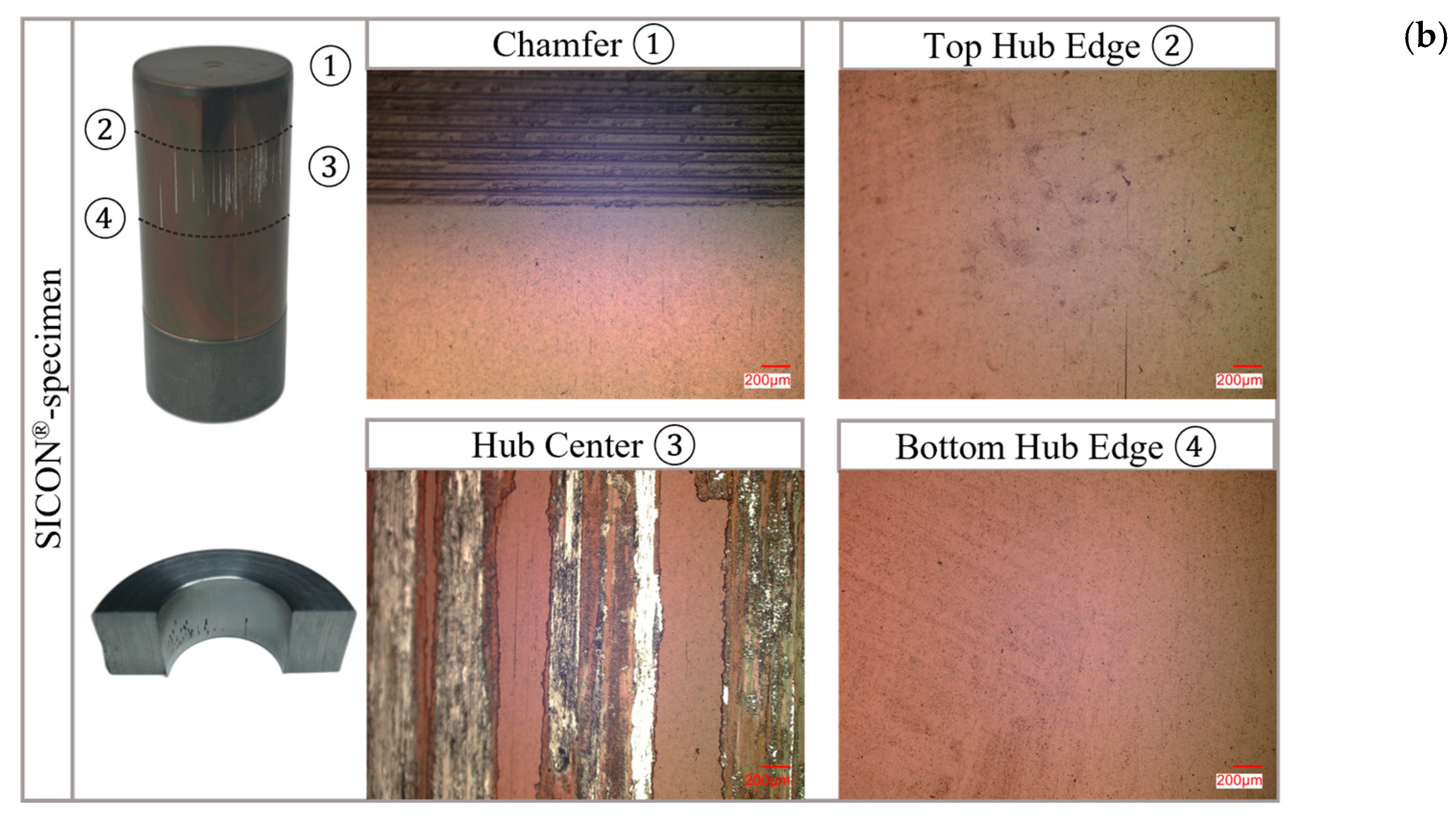
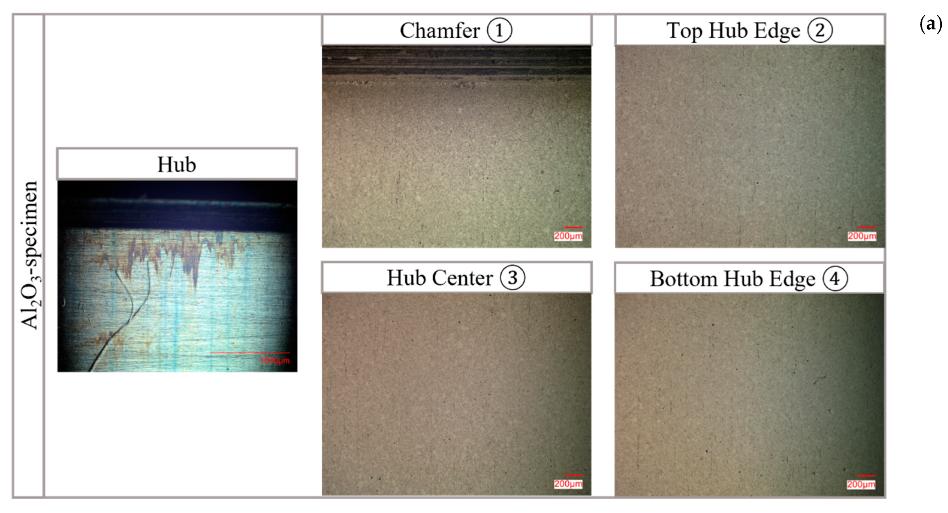
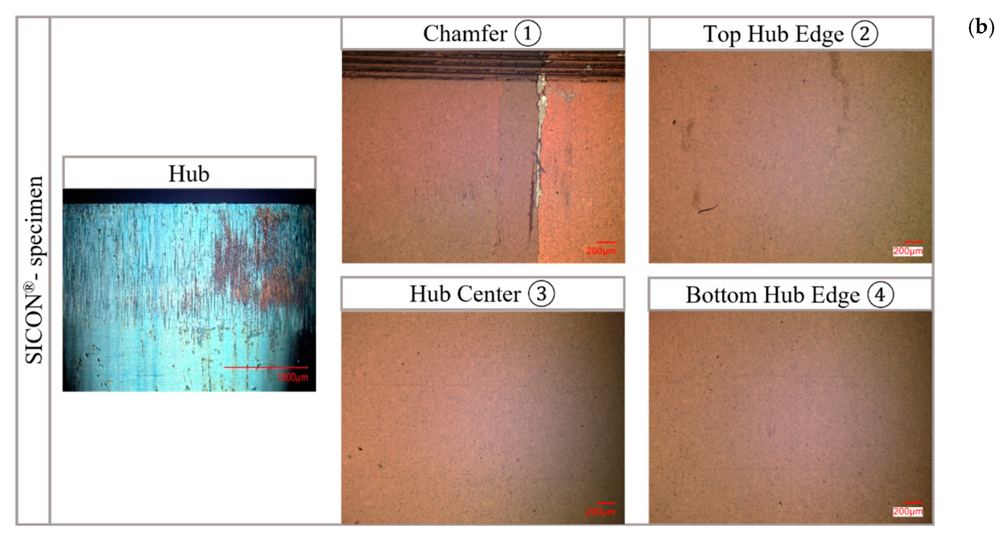
A conservative design approach uses the thermal expansion coefficients of the coatings (see Figure 1b) for α s h a f t . In order to achieve the same intended interference, the lower thermal expansion coefficient of the coating necessitates a greater temperature difference between the shaft or hub and the ambient environment. A joining clearance of approximately 2∙U = 0.06 mm (temperatures of Tshaft = −73 °C and Thub = 300 °C) resulted in a consistently successful joining process. The increased joining clearance is attributable to the coating’s sensitivity, necessitating avoidance of contact with the hub during the joining process. The microscope images taken for both thin-film systems are shown in Figure 6.
Despite the additional joining clearance, significant damage occurred to the chamfer edge in several specimens in both thin-film systems. The damage to the chamfer edge can be attributed to insufficient centering during joining, resulting from the thermal expansion of the entire system (shaft and coating), inhomogeneous heating/cooling, and deviations in specimen geometry. Since no sensors are attached to the chamfer, this wear is not considered critical for the application.

4.1.3. Intermediate Summary

Shrink-fits were chosen as the preferred joining method due to the lower level of damage observed. In contrast, press-fits resulted in significant surface damage, despite proper centering, due to the interference that needed to be overcome and the unformed oil-lubrication film. With the current specimen geometry, contact pressure measurement in the SHC, joined as press-fits, is not feasible and will not be considered in further experimental investigations. Reducing the interference is hardly feasible without compromising sensor functionality, as the sensors require a minimum contact pressure of 100 MPa to operate reliably. In comparison, shrink-fits show only minor damage on the chamfer, which leads to no sensor failure. Increasing the temperature difference between the shaft and hub enlarges the joining clearance, offering the potential for damage-free joining, thus preserving the functionality of the thin-film system. The realization of this potential is further explored in the following subsection.

4.2. Maximum Temperature Difference During Joining as a Shrink-Fit

The maximum available joining clearance is influenced by the maximum possible temperature difference (Thub,max and Tshaft,min to Tamb). This also extends the time frame for joining.
The maximum temperature of the hub is not limited by the tempering temperature due to the chosen material, and this was investigated first. Tests were conducted up to Thub = 350 °C for both thin-film systems. The microscopic examinations, conducted as described in Section 3, showed no significant findings for either of the thin-film systems. The COFs listed in Table 2 were determined by the loosening process (pressing out the shaft) and were in line with expectations and slightly higher than those of steel–steel contacts. At higher hub temperatures, graphitization is possible with the SICON®-coating. Graphitization for DLC coatings at temperatures of 300 °C and above have been documented in numerous publications [16,17,18] for DLC coatings. During this process, the coating undergoes oxidation, graphitization, and dehydration, leading to the formation of a transfer layer and the release of wear particles [17]. This results in an increased wear rate and a reduction in the COF [17], which negatively impacts the functionality and design of the SHC. It is assumed that no graphitization of the SICON®-coating occurred since the exposure of the shaft to critical temperatures is very short because of the high temperature difference and the subsequent equalization between shaft and hub. The experimentally determined COF also indicates that no graphitization has taken place.
Once the maximum joining temperature of the hub is uniformly set to 300 °C for both thin-film systems, the minimum temperature of the shaft is investigated. Since the minimum temperature has already been successfully tested in a climate chamber, the cooling of the shaft with liquid nitrogen to −195.8 °C is examined. As no damage was observed on the Al2O3-specimen, only the microscope images of the SICON®-specimen are shown in Figure 7.
As shown in the picture, the thin-film system on the top hub edge has detached in strips along the entire circumference on the top hub edge making a subsequent measurement impossible. Since no visible damage is observed in the longitudinal direction or at the center of the contact area, it is assumed that the defect is caused by excessive stresses. Further microscopic examinations, as well as tactile and optical surface profile measurements indicate failure at the interface between the second and third layer as well as within the third layer, presumably at the interface. This is reasonable, as it is the only location where the two investigated thin-film systems differ in their structure. It is assumed that delamination results from the complex stress state within the thin-film system, which is influenced by both thermal and mechanical stresses. Thermal stresses arise from the mismatch in thermal expansion coefficients during the cooling of the shaft and the joining with the heated hub. Mechanical stresses develop due to the formation of contact pressure and the resulting radial constriction of the shaft. These combined effects lead to high stresses at the interface and residual stresses within the layers. The stresses are relieved by cracking and delamination (=blistering) [19]. Upon contact with a counter body (=hub), the blisters are ruptured, leading to formation of craters [19]. Due to the lack of accessibility from the surface, crack formation is not microscopically detectable after the joining process, making it in this case impossible to determine the exact time at which the damage occurs.
It was experimentally proven that the SICON®-specimen can be joined with Tshaft = −73 °C und Thub = 300 °C and the Al2O3-specimen with Tshaft = −195.8 °C and Thub = 300 °C, whereby higher hub temperatures were not investigated.

5. Discussion

In the following Section 5.1, the design recommendations are summarized based on the results of the experimental investigations and are described as generally as possible, without reference to the specific thin-film system used, in order to ensure broad applicability. In Section 5.2 the design recommendations are reflected.

5.1. Summary of Design Recommendations

The most important key findings are summarized in Table 3.

5.2. Reflection on Findings

An experimental approach was chosen for the investigation, as no existing failure model for the thin-film system is available for simulative analysis.
Due to the lower level of damage observed, shrink-fits are preferred over press-fits as the joining method. Further investigations into the formation of an adequate lubrication film are needed to assess the use of press-fits for coated SHCs. Since the focus of this publication is on a simple, universally applicable geometry with minimal space requirements, these investigations have not been conducted. However, optimization proposals have been developed based on parameters to be explored, demonstrating the potential for nearly damage-free joining.
The coating substrate for both press- and shrink-fits is the shaft, chosen for its accessibility.
  • Press-fits
Lubrication behavior (lubricant selection and application) plays a crucial role in the damage during the joining process. Ideally, the application of a suitable lubricant forms a protective lubricating film on the coating during joining. During the resting time, this lubricating film gradually exits the contact area, leading to an increase in the coefficient of friction. When selecting an appropriate lubricant, both the wetting behavior on the coating and the manufacturing process of the hub bore need to be considered. While the wetting behavior of the lubricant on the coating can only be determined through preliminary experimental tests, the manufacturing process must be evaluated in terms of any existing machining grooves. In the case of contact surfaces without machining grooves (e.g., polished, honed, or superfinished), the complete transport of the lubricant into the contact area is hindered. It is advisable to use a lubricant that is difficult to “scrape off” during joining due to the chemical bonds that form with the coating. After joining, the lubricant remains in the contact area. However, if there are contact surfaces with machining grooves (e.g., caused by turning or grinding), the use of viscous lubricating oils is recommended. These oils can collect in the machining grooves and enter the contact area, where they will flow out once the joining process is complete. Regardless of the method used to manufacture the contact surfaces, it is recommended that both contact surfaces are lubricated.
The geometry of the chamfer requires further optimization. If the available installation space allows, a longer chamfer with rounding, as described by [20], is a good option. This ensures uniform expansion of the hub, minimizing damage to the shaft surface during joining. If there is not enough installation space, a removable joining device described by [20] can be used as a replacement for the chamfer. The functional principle of this device is similar to that of the longer chamfer. The outer diameter of the detachable joining device is larger than that of the shaft, allowing for pre-expansion of the hub to a certain interference [20].
  • Shrink-fits
Damage-free joining as shrink-fits is achievable provided that specific process parameters are met.
The interference of the shrink-fit is limited by the required minimum joining clearance and the maximum possible temperature difference between the joining temperatures. Since a contact between the shaft and the hub during assembly leads to damage to the coating, a minimum joining clearance larger than that specified in the DIN standard [4] must be provided. The necessary joining clearance should be at least 2∙U, due to the different thermal expansion coefficients of the coating and the substrate, and the resulting lower thermal contraction of the coated body. A joining device with sufficient centering, as described according to the functional principle in Section 2.3, is essential to ensure that the coating does not come into contact with the mating body while the hub has not yet reached its final position. In general, the maximum and minimum joining temperatures of the SHC must be adapted to the required joining clearance. An oversized joining clearance causes higher temperature differences, which proportionally increase the thermally induced residual stresses within the coating and at the interfaces. This increases the risk of cracking and even delamination of the coating to relieve stress. The maximum hub temperature is limited by the tempering temperature, which is why a heat treatment process is recommended for the hub material. With DLC coatings, the temperature is limited to 300 °C due to potential graphitization, which can have a detrimental effect on the COF and the wear rate as reported in the literature. For the maximum possible temperature difference during joining, and thus the potential oversize, the thermal mismatch of the thin-film system, especially at the outermost interface, is relevant. If similar thermal mismatches are present as in this publication, the joining temperatures used here can serve as a guideline. For lower thermal mismatches, higher temperature differences are possible, but their feasibility needs to be experimentally investigated. A significantly higher interference than the one used here will not be feasible due to the thermally induced stresses.
The chamfer can be optimized with respect to the specimen geometry. Due to the numerous, unavoidable influences on the centering accuracy of the components, additional centering of the hub to the shaft via the chamfer of the shaft is required. This is necessary because even minimal contact between the components can damage the coating. This can be achieved using an extended chamfer with rounding or a removable joining device, as described for the press-fit. It should be noted that the chamfer and adapter are uncoated to prevent detached coating parts from entering the contact area upon contact.
The coating’s material can be used to influence the thermally induced stresses. The use of a material with a similar coefficient of thermal expansion to the substrate material is therefore recommended.
Regarding the joining device, the focus is on guiding the two components in relation to each other. With the specimen geometry used here, guidance is only possible via the outer surface of the hub. The shaft is coated over its entire length, which excludes guidance on this surface. The guide length l of the hub is too short with l/Dguide surface = 0.3 and is susceptible to tilting. A minimum guide length l of l/Dguide surface = 1, determined from experimental tests, is recommended. A change to the specimen geometry used here and a redesign of the joining device for further preliminary tests is therefore necessary.

6. Summary and Outlook

Experimental investigations demonstrate that joining coated SHCs can be achieved without damage that affects functionality, thereby confirming the feasibility of contact pressure measurement using thin-film sensors in cylindrical interference-fits.
In this publication, two thin-film systems relevant to the application of thin-film sensors were applied to the shafts of interference-fits and analyzed following the established test approach. Both thin-film systems consist of three functional layers with a total thickness of approximately 6 μm, with a ceramic layer (Al2O3) as the first layer and a metal layer as the middle layer being identical in both systems. The difference lies in the outermost layer, where one system uses a ceramic (Al2O3) layer and the other a DLC (a-C:H:Si:O) layer (see Section 2). The purpose of the thin-film systems investigated in this publication is to measure the contact pressure in the contact area of the SHC using a sensor system integrated into the coating. The SHCs were joined as either press- or shrink-fits and subsequently examined microscopically for any damage. Since structuring of the sensor layer was not performed in the scope of this study, the layer was applied over a large area to represent the system as a whole. It was found that, in case of press-fits with an oiled shaft, the interference to be overcome in both thin-film systems led to asymmetric damage on the shaft’s surface around the entire circumference, rendering the coating unsuitable for functional use.
Feasibility as shrink-fits is possible if the minimum joining clearance U is increased from 0.001∙DF according to standard [4] to 2∙U. This was further investigated in terms of the possible joining temperatures of the shaft and hub to optimize the joining process and determine the limits. The feasible joining temperatures differ between the thin-film systems investigated. While the investigated temperatures of Thub = 350 °C and Tshaft = −195.8 °C did not cause any damage with the Al2O3-specimens, two anomalies occurred with the SICON®-specimens. Joining with nitrogen-cooled shafts is likely to lead to delamination around the complete circumference on the edge of the hub, due to thermally induced stresses caused by the mismatch of the thermal expansion coefficients of the substrate and the coatings. Furthermore, graphitization can occur in the DLC layer at a hub temperature of 300 °C, leading to the formation of a transfer layer. This negatively impacts wear behavior, and, as demonstrated, the COF. Based on the results, generally applicable design recommendations for the joining of coated SHCs were derived. For press-fits, potential areas for damage-free joining were identified and further investigated.
The application of thin-film systems for measuring the contact pressure in interference-fits aims to determine the influence of the coatings on the torque transmission behavior through experimental investigations. The specimens will be joined exclusively as shrink-fits, following the identified design recommendations and using an improved joining device. The results from the joining and torsion tests will provide a solid foundation for identifying the most suitable thin-film system and will investigate the impact on both the service life and the transferable torsional moment. From this, the potential for its use as a smart machine element can be assessed.

Author Contributions

Conceptualization, C.B., M.P., M.K., and G.B.; methodology, C.B., M P., and C.P.; validation, C.B., M.P., and C.P.; formal analysis, C.B.; investigation, C.B., M.P., and C.P.; resources, M.K., and G.B.; data curation, C.B., M.P., and C.P.; writing—original draft preparation, C.B. and M.P.; writing—review and editing, C.P., M.W., M.K., and A.S.; visualization, C.B.; supervision, M.K., M.W., A.S., and G.B.; project administration, C.B., M.P., and C.P.; funding acquisition, M.K., and G.B.; All authors have read and agreed to the published version of the manuscript.

Funding

This research was funded by the German Research Foundation, Deutsche Forschungsgemeinschaft (funding numbers: KR 5777/1-1 & BR 2178/70-1), with the project number 511576481.

Data Availability Statement

The data presented in this study are available on request from the corresponding author.

Acknowledgments

During the preparation of this manuscript, the authors used ChatGPT-5 for the purposes of text editing. The authors have reviewed and edited the output and take full responsibility for the content of this publication.

Conflicts of Interest

The authors declare no conflicts of interest.

Abbreviations

The following abbreviations are used in this manuscript:
SHCShaft-hub connection
COFStatic coefficient of friction

References

  1. Kollmann, F.G. Welle-Nabe-Verbindungen—Gestaltung, Auslegung, Auswahl; Springer: Berlin/Heidelberg, Germany, 1984. [Google Scholar] [CrossRef]
  2. Leidich, E. Welle-Nabe Verbindungen. In Konstruktionselemente des Maschinenbaus; Sauer, B., Ed.; Springer: Berlin, Germany, 2023; Volume 10, pp. 519–599. [Google Scholar] [CrossRef]
  3. Smetana, T.; Walther, V. Welle-Nabe-Verbindungen in der Elektromobilität—Automobile Verbindungstechniken im 21. Jahrhundert am Beispiel Elektrischer Fahrzeugantriebe; VDI-Berichte 2238; VDI Verlag GmbH: Düsseldorf, Germany, 2014. [Google Scholar]
  4. DIN 7190-1; Pressverbände-Teil 1: Berechnungsgrundlagen und Gestaltungsregeln für Zylindrische Pressverbände. DIN Media GmbH: Berlin, Germany, 2017.
  5. Breuning, C.; Kreimeyer, M.; Plogmeyer, M.; Pongratz, C.; Schott, A.; Bräuer, G. Untersuchung des Einsatzpotenzials Eines Multisensorischen Dünnschichtsystems zur Messung des Fugendrucks in Reibschlüssigen Welle-Nabe-Verbindungen; VDI-Berichte 2443; VDI Verlag GmbH: Düsseldorf, Germany, 2024. [Google Scholar]
  6. Bobzin, K.; Kalscheuer, C.; Möbius, M.P.; Hassanzadegan Aghdam, P. Thermal stability of thick α– and γ-Al2O3 coatings deposited by high-speed PVD. Surf. Coat. Technol. 2024, 447, 130411. [Google Scholar] [CrossRef]
  7. Horii, T.; Kirihara, S.; Miyamoto, Y. Freeform fabrication of Ti-Al alloys by 3D micro-welding. Intermetallics 2008, 16, 1245–1249. [Google Scholar] [CrossRef]
  8. Champi, A.; Lacerda, R.G.; Viana, G.A.; Marques, F.C. Thermal expansion dependence on the sp2 concentration of amorphous carbon and carbon nitride. J. Non-Cryst. Solids 2004, 338–340, 499–502. [Google Scholar] [CrossRef]
  9. Bobzin, K.; Brögelmann, T.; Kruppe, N.C.; Janowitz, J. Temperature measurement on tool surfaces by wear resistant PVD sensor coatings. Defect Diffus. Forum 2020, 404, 138–145. [Google Scholar] [CrossRef]
  10. Sperrfechter, T.; Haller, R. Elastohydrodynamic lubrication between rolling and sliding ceramic cylinders: An experimental investigation. J. Tribol. 2000, 122, 721–724. [Google Scholar] [CrossRef]
  11. Corbella, C.; Bialuch, I.; Kleinschmidt, M.; Bewilogua, K. Modified DLC coatings prepared in a large-scale reactor by dual microwave/pulsed-DC plasma-activated chemical vapour deposition. Thin Solid Film. 2008, 517, 1125–1130. [Google Scholar] [CrossRef]
  12. Emmrich, S.; Plogmeyer, M.; Bartel, D.; Herrmann, C. Development of a Thin-Film Sensor for In Situ Measurement of the Temperature Rise in Rolling Contacts with Fluid Film and Mixed Lubrication. Sensors 2021, 21, 6787. [Google Scholar] [CrossRef] [PubMed]
  13. Gräfensteiner, M. Gecko TP I—Analyse und Synthese Charakterisierender Kennwerte zur Funktionsgerechten Gestaltung von Wirkflächenpaaren in Reibschlüssigen Verbindungen; FVA final Report; Forschungsvereinigung Verbrennungskraftmaschinen: Frankfurt, Germany, 2014. [Google Scholar]
  14. Biederstedt, W. Presspassungen im Elastischen, Elastisch-Plastischen und Plastischen Verformungsbereich. Ph.D. Thesis, Hochschule Hannover-University of Applied Sciences and Arts, Hannover, Germany, 1963. [Google Scholar]
  15. Kalin, M.; Polajnar, M. The wetting of steel, DLC coatings, ceramics and polymers with oils and water: The importance and correlations of surface energy, surface tension, contact angle and spreading. Appl. Surf. Sci. 2014, 293, 97–108. [Google Scholar] [CrossRef]
  16. Tallant, D.R.; Parmeter, J.E.; Siegal, M.P.; Simpson, R.L. The thermal stability of diamond-like carbon. Diam. Relat. Mater. 1995, 4, 191–199. [Google Scholar] [CrossRef]
  17. Zeng, Q.; Ning, Z. High-temperature tribological properties of diamond-like carbon films: A review. Rev. Adv. Mater. Sci. 2021, 60, 276–292. [Google Scholar] [CrossRef]
  18. Zhang, T.F.; Wan, Z.X.; Ding, J.C.; Zhang, S.; Wang, Q.M.; Kim, K.H. Microstructure and high-temperature tribological properties of Si-doped hydrogenated diamond-like carbon films. Appl. Surf. Sci. 2018, 435, 963–973. [Google Scholar] [CrossRef]
  19. Dearnley, P.A.; Elwafi, A.M.; Chittenden, R.J.; Barton, D.C. Wear and Friction of Diamond like-Carbon Coated and Uncoated Steel Roller Bearings Under High Contact Pressure Oil Lubricated Rolling/Sliding Conditions. J. Tribol. 2014, 136, 021101. [Google Scholar] [CrossRef]
  20. Falter, J.; Herburger, D.; Binz, H.; Kreimeyer, M. An Investigation of Increased Power Transmissions Capabilities of Elastic-Plastic-Designed Press-Fit Connections Using a Detachable Joining Device. Eng 2024, 5, 1155–1172. [Google Scholar] [CrossRef]
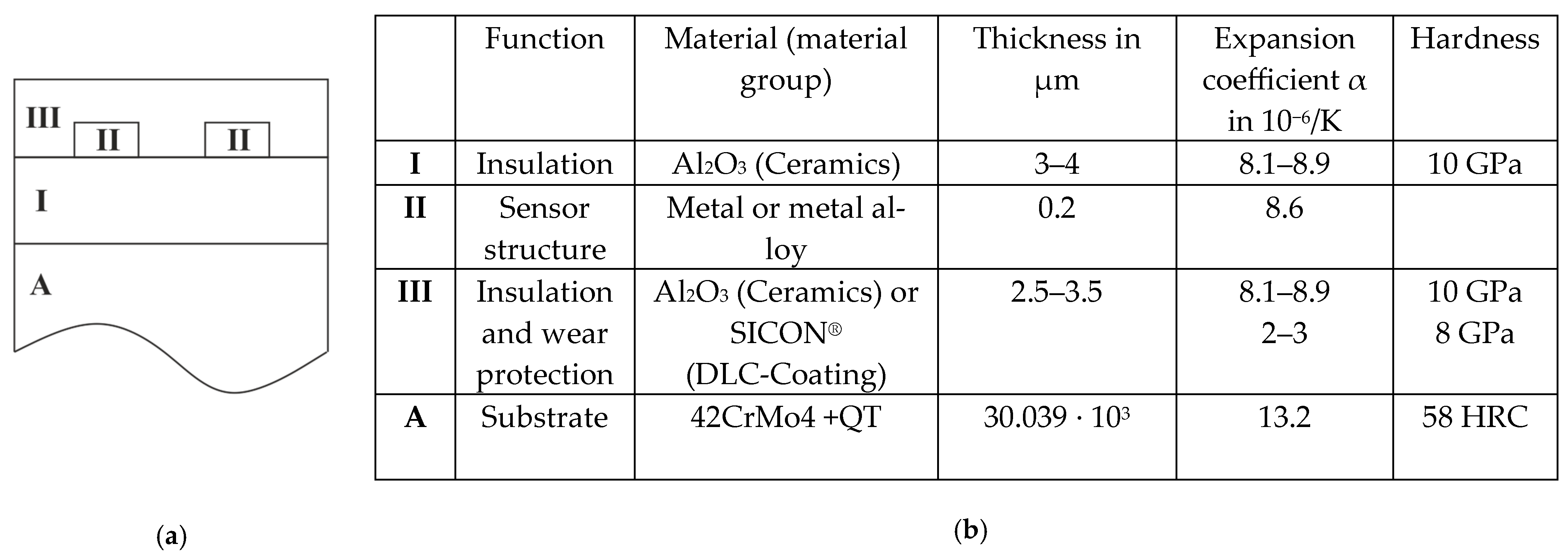
Figure 1. (a) Overview of the overall thin-film sensor system applied on the substrate A; (b) function and properties of the layers with thermal expansion coefficents according to [6,7,8].
Machines 13 00776 g001
Figure 2. Specimen geometry; (a) shaft; (b) hub; (c) dimensions of the shaft and hub.
Machines 13 00776 g002
Figure 3. (a) Joining device for press-fits; (b) joining device for shrink-fits.
Machines 13 00776 g003
Figure 4. Overview of the used test approach with dotted lines representing the exemplary measurement curve of the coordinate measuring machine.
Machines 13 00776 g004
Figure 5. Damages after joining as a press-fit; (a) with Al2O3 thin-film system; (b) SICON® thin-film system.
Machines 13 00776 g005aMachines 13 00776 g005b
Figure 6. Damage during joining as a shrink-fit; (a) Al2O3-specimen; (b) SICON®-specimen.
Machines 13 00776 g006aMachines 13 00776 g006b
Figure 7. Microscope images and profile of a specimen joined as a shrink-fit (Tshaft = −195.8 °C and Thub = 300 °C).
Machines 13 00776 g007
Table 1. Possible temperature ranges for the cooling of the shaft.
FridgeFreezerDry IceClimatic ChamberLiquid Nitrogen
Temperature ranges7 °C−15 to −22 °C−78.4 °C [4]−73 to 250 °C−195.8 °C [4]
Table 2. Overview of COFs.
Al2O3SICON®Steel
μstatic with lubrication (press-fit)0.15 *0.097 *0.08 [14]
μstatic without lubrication (shrink-fit)0.181 *0.169 * 0.12 [14]
* experimentally determined on one sample.
Table 3. Key findings about the joining of coated SHCs.
Key FindingsDetails
Preference for shrink-fits over press-fits
  • Damage-free joining as shrink-fits is possible
  • Contact between components during joining damages the coating
  • Further investigations are necessary for the potential use of press-fits
Joining temperatures
  • Recommendation of a minimum joining clearance of 2∙UsΘ
  • High temperature difference between shaft and hub causes high stresses at the interfaces and in the layers, which are dissipated via cracks and delamination and limit the torque transmission capacity
  • Suitable heat treatment of the hub material to avoid limitation of the maximum temperature due to structural changes
  • Use of DLC-coatings limited to 300 °C due to potential graphitization
Specimen geometry
  • Recommendation of a long chamfer or a removable joining device, as reported in [20] for centering the components outside the coated area if installation space is limited
  • Consideration of a minimum guide length of l/Dguiding surface ≥ 1
  • Guiding surface should not be coated
  • Always round off the front hub edge
Selection of the coating
  • Material with similar thermal expansion coefficient as substrate to avoid thermally induced stresses
Disclaimer/Publisher’s Note: The statements, opinions and data contained in all publications are solely those of the individual author(s) and contributor(s) and not of MDPI and/or the editor(s). MDPI and/or the editor(s) disclaim responsibility for any injury to people or property resulting from any ideas, methods, instructions or products referred to in the content.