Abstract
The electromagnetic vibration characteristics of doubly fed induction machines (DFIMs) employed in variable-speed pumped storage units, which must accommodate frequent power response and operational mode transitions, serve as critical indicators for assessing unit safety and stability. Nevertheless, there persists a significant research gap regarding generalized vibration analysis models and comprehensive investigations into their steady-state and dynamic vibration performance. To address this challenge, this study develops a universal analytical model for electromagnetic excitation forces in DFIMs using Maxwell’s stress tensor method, explicitly incorporating operational conditions such as rotor eccentricity and load imbalance. Using a 300 MW DFIM as a case study, we employ a hybrid numerical-analytical approach to examine the detrimental effects of harmonic currents generated by rotor-side converters. Furthermore, we systematically analyze how spatial harmonics induced by mechanical faults and temporal harmonics arising from electrical faults collectively influence the electromagnetic vibration behavior. Experimental validation conducted on a 10 MW DFIM prototype through vibration displacement measurements confirms the efficacy of the proposed analytical framework.
1. Introduction
Variable-speed pumped storage (VSPS) power plants utilize doubly fed induction machines (DFIMs) coupled with pump turbines to achieve energy conversion. The systems exhibit constant-frequency speed regulation, flexible power adjustment, and rapid dynamic response, making them critical assets for peak-shaving, frequency regulation, and grid stabilization in modern power systems [1,2,3]. As the core energy conversion component, the DFIM needs to adapt to frequent power response and condition switching; therefore, its vibration characteristics critically affect operational safety and serve as key metrics for electromechanical design evaluation [4,5]. Consequently, the systematic investigation of vibration behavior in DFIMs for VSPS is essential and significant.
Compared with the wound-field synchronous machines used in conventional fixed-speed units, DFIMs are equipped with rotor-side converters for excitation, with capacity typically representing 20–30% of the total unit capacity [6,7]. While enabling improved flexibility and dynamic characteristics, these converters also introduce significant high-frequency harmonic currents that severely affect machine vibration [8]. Experimental results from small-scale prototypes demonstrate that the harmonic currents from rotor-side converters exacerbate vibrations in both low and high frequency ranges [9,10]. Furthermore, the converter topology significantly influences machine vibration. Three-level topologies generate lower harmonic current content compared to two-level topologies, effectively reducing vibration amplitudes [11]. Ref. [12] first investigated the radial electromagnetic force distribution characteristics in a 336 MW DFIM under the influence of low-frequency time harmonics from rotor-side converters but did not further discuss the machine’s vibration behavior. Presently, there remains a notable scarcity of analytical tools capable of comprehensively characterizing vibration behavior in DFIMs across multiple operating conditions.
In addition to normal operation, the vibration characteristics of DFIMs under abnormal operating conditions containing significant spatial and temporal harmonics warrant particular attention. The primary concern is rotor eccentricity, which introduces spatial harmonics. Rotor eccentricity occurs when the rotor axis deviates from the stator center, resulting in non-uniform air-gap length [13]. This condition can arise from manufacturing imperfections or bearing degradation during prolonged operation [14]. Under eccentricity faults, the distribution characteristics of radial electromagnetic forces undergo significant modifications, introducing new frequency and spatial harmonic components that increase resonance risks [15,16]. Ref. [17] established an analytical model of radial electromagnetic forces under DFIM eccentricity faults, investigating force distribution patterns under both static and dynamic eccentricity conditions. Refs. [18,19] proposed suppression methods through harmonic current injection achieved via rotor winding group excitation and auxiliary excitation windings, respectively. In VSPS power plants, vertically mounted DFIMs are directly coupled to pump turbines. When hydraulic forces induce mechanical displacement in the turbine, this displacement transmits directly to the machine’s rotor, causing slight eccentricity [20]. To ensure operational safety and stability, and to provide theoretical foundations for protection relay system design, the comprehensive investigation of DFIM vibration characteristics under rotor eccentricity faults is essential.
Another critical category involves external electrical faults that introduce substantial temporal harmonics. In VSPS plants, the stator windings of DFIMs connect directly to the grid through the main transformer, allowing grid-side disturbances and harmonics to propagate into the machine [21]. When grid asymmetries occur due to unbalanced loads, single-phase reclosing, or external asymmetrical faults, negative-sequence currents emerge in the system [22,23,24]. Upon entering the DFIM stator windings, these currents generate a counter-rotating magnetic field that cuts the rotor at nearly twice synchronous speed. This phenomenon not only increases eddy current losses in the rotor core and subjects the shaft to alternating torques but also alters the distribution characteristics of radial electromagnetic forces, consequently affecting the machine’s vibration behavior [25,26]. Previous studies have systematically investigated vibration mechanisms in various electrical machines under asymmetric operating conditions. Ref. [27] examined the vibration characteristics of synchronous generators under load imbalance, identifying two distinct electromagnetic force waves induced by negative-sequence currents as the primary cause of vibration intensification. In nuclear power applications, Ref. [28] analyzed electromagnetic force variations at the critical rotor nodes of turbine generators during incomplete phase operation, establishing theoretical foundations for rotor structure optimization. For hydro-generators, [29] demonstrated significant electromagnetic force increases in damper windings under unbalanced load conditions. The rotor structure of large-capacity DFIMs exhibits distinct characteristics compared to that of conventional nonsalient-pole and convex-pole hydro-generators [30,31]. More significantly, under grid asymmetry conditions, the distribution of radial electromagnetic forces induced by negative-sequence currents demonstrates unique time-varying characteristics influenced by slip frequency. This necessitates the development and validation of corresponding theoretical models to elucidate the vibration behavior distribution patterns of DFIMs under unbalanced load conditions.
To address the limitations in prior studies, this work systematically investigates the vibration characteristics of large DFIMs employed in VSPS. The remainder of this work is organized as follows. Section 2 derives a universal analytical model of radial electromagnetic forces in DFIGs, considering both rotor converter harmonic currents and faults (including rotor eccentricity and load asymmetry), with a detailed analysis of the electromagnetic force harmonic distributions. Section 3 takes a 300 MW DFIG as the research object, where the finite element method verifies the characteristic electromagnetic force components under different operating conditions and investigates the electromagnetic vibration characteristics through harmonic response analysis, proposing selection criteria for rotor converter switching frequencies. Finally, the validity of the proposed analytical approach is confirmed by comparative experiments on vibration displacement using a 10 MW DFIM test rig.
2. Analytical Model for Electromagnetic Force
DFIMs in VSPS power stations face complex operating conditions, including rotor eccentricity, asymmetric stator loading, and unbalanced rotor excitation. To analyze electromagnetic vibration characteristics under these extreme scenarios, this paper establishes a generalized analytical model based on the magnetomotive force-permeance (MMF-Permeance) method and Maxwell stress tensor theory. The proposed model provides theoretical guidance for vibration assessment across diverse fault conditions.
2.1. Normal Operating Conditions
The normal operation of the DFIM refers to its fault-free running state with excitation provided by the rotor-side converter. Under normal conditions, the rotor excitation current can be expressed as
where k denotes the harmonic order of the rotor current, wf represents the fundamental frequency of the rotor excitation current, φk indicates the initial phase angle of the k-th order harmonic current, wm denotes the switching device frequency, a and b represent integer multiples of the switching frequency and rotor fundamental frequency, respectively (with opposite parity) [7], and φab indicates the initial phase angle of the switching sideband harmonic current.
Under rotor-side converter excitation, the MMF function in a DFIM can be expressed as
where ws denotes the grid angular frequency and p represents the number of motor pole pairs. ν indicates the harmonic order of stator phase-belt MMF, s is the motor slip ratio, γ corresponds to the phase-belt MMF harmonic order of rotor low-frequency currents, and τ specifies the phase-belt MMF harmonic order of rotor sideband harmonic currents.
Considering the influence of stator and rotor slotting effects on the air-gap permeance function in DFIM, and neglecting higher-order terms, the permeance can be expressed as
where k1 and k2 denote the harmonic orders of stator slotting and rotor slotting, respectively; Z1 and Z2 represent the number of stator slots and rotor slots; Kc is the Carter coefficient; m0 stands for the permeability of vacuum; and g0 denotes the air-gap length.
The air-gap flux density of the DFIM can be expressed as
In DFIM, the radial electromagnetic force density exhibits complex harmonic components. However, the electromagnetic vibration amplitude is directly proportional to the force magnitude and inversely proportional to the fourth power of its spatial order. Consequently, only low-order force waves with significant amplitudes dominantly affect vibration behavior. By neglecting secondary force waves, the dominant electromagnetic force density can be expressed as
Among various electromagnetic force components, the primary contributors to machine vibration include (1) high-frequency 2 p-order force waves generated by the interaction between the fundamental magnetic field and current harmonics near the converter switching frequency and its multiples, forces that may resonate with the machine’s natural frequencies; (2) low-order force waves induced by near-slot stator-rotor combinations, which exhibit broad frequency distribution due to rotor rotation modulation; and (3) low-order high-amplitude force waves caused by the interaction of stator and rotor phase-belt MMF harmonics.
2.2. Rotor Eccentricity
Rotor eccentricity is one of the most common mechanical faults in electrical machines. Dynamic eccentricity occurs when the rotor geometric center O1 does not coincide with the rotational center O2, while static eccentricity refers to cases where the rotor geometric center is offset from its nominal position but remains aligned with the rotational center.
The schematic diagram of the DFIM rotor eccentricity is shown in Figure 1 [32]. Eccentricity (δs/δd) is defined as the normalized displacement between rotor and stator centers e/g0 [17].
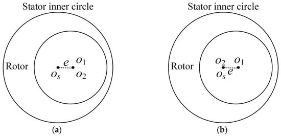
Figure 1.
Schematic diagram of rotor eccentricity: (a) static eccentricity and (b) dynamic eccentricity.
The air-gap permeance function is modified to account for eccentricity effects and expanded using binomial series:
where δs denotes the static eccentricity ratio and δd represents the dynamic eccentricity ratio.
Under rotor eccentricity conditions, the air-gap flux density is modified as
The modified flux density expression reveals that rotor eccentricity introduces sideband harmonics to the original spectrum. Static eccentricity solely modifies harmonic orders, whereas dynamic eccentricity simultaneously alters both harmonic frequencies and orders. The additional radial electromagnetic force waves induced by rotor eccentricity can be derived as
Equation (7) reveals that rotor eccentricity significantly complicates the composition of radial electromagnetic forces. In addition to the newly generated 1st-order force waves, ±1-order sidebands emerge around original force wave harmonics, with their amplitudes proportional to the eccentricity ratio. For static eccentricity, vibration analysis should focus on the influence of these new spatial orders, whereas dynamic eccentricity additionally introduces frequency modulation effects on existing force wave components.
2.3. Asymmetric Load
In power systems, negative-sequence currents arise from faults (e.g., line breaks, incomplete-phase reclosing) or load imbalances. These currents generate a counter-rotating magnetic field that redistributes radial electromagnetic forces, consequently exacerbating machine vibration. This section derives the radial electromagnetic forces in DFIMs under unbalanced load conditions using the symmetrical component method and Maxwell stress tensor theory, subsequently characterizing the spatiotemporal properties of force harmonics under negative-sequence operation.
According to the symmetrical component method, unbalanced three-phase stator currents can be decomposed into balanced positive-sequence, negative-sequence, and zero-sequence components, expressed as
where a denotes the complex phase operator ej2π/3.
Each sequence current generates a corresponding MMF in the machine: Positive-sequence currents produce forward-rotating MMF, negative-sequence currents create backward-rotating MMF, while zero-sequence currents produce no net MMF due to phase cancellation. Thus, the stator current-induced MMF function can be expressed as [25]
The negative-sequence magnetic field produced by stator currents will cut through rotor windings at approximately twice the rotor speed, inducing corresponding currents expressed as
Therefore, in the stator reference frame, the MMF produced by the rotor excitation windings can be expressed as
Similarly, by employing the magnetomotive force-permeance method and Maxwell stress tensor theory, the additional radial electromagnetic forces induced under unbalanced load conditions can be derived as
As evident from (11), the magnetic field generated by negative-sequence currents significantly complicates the composition of radial electromagnetic forces. This manifests as new frequency components superimposed on existing force wave orders, substantially increasing the risk of exciting mechanical resonances in the machine.
2.4. Vibration Characteristic Analysis
The radial electromagnetic forces acting on the stator core exhibit periodic variations synchronized with the rotating air-gap magnetic field, manifesting externally as machine vibration and acoustic noise. The stator core can be analytically modeled as a single-ring structure to compute these vibrational characteristics.
To simplify the analysis, the stator core is modeled as a ring structure, with the effects of stator teeth and windings accounted for through additional mass, while damping is neglected. The equivalent stator mass mm is expressed as [33]:
where G represents the stator core weight, Rj denotes the average yoke radius, lFe is the effective core length, and g stands for gravitational acceleration.
The compliance of the stator core is calculated as follows:
where hj is the stator yoke height, E represents the elastic modulus of the stator core, and n denotes the number of nodal diameters (mode order).
The natural frequency fc is calculated as
The mechanical impedance of the stator is given by
The vibration velocity on the stator surface is calculated as
where F represents the amplitude of the electromagnetic force wave and Rδ denotes the air-gap radius.
Vibration amplitude is directly proportional to both the proximity between the excitation frequency and natural frequency and the magnitude of excitation force. Given that natural frequencies are determined by the stator yoke’s average radius and height, strategically modifying motor dimensions to prevent force wave frequencies from coinciding with structural resonances constitutes an effective vibration suppression measure.
3. Vibration Characteristics Under Different Operating Conditions
DFIMs in VSPS face multiple special operating conditions, where the distribution of radial electromagnetic forces varies significantly across different scenarios, leading to distinct vibration behaviors. To provide references for the vibration-conscious electromagnetic design of large DFIMs and establish theoretical foundations for fault detection, this section investigates the vibration characteristics under diverse operational conditions through FEA.
3.1. Modal Analysis
The calculation of stator core natural frequencies forms the foundation for analyzing motor vibration characteristics. This paper conducts subsequent research using a 300 MW DFIM as a case study. Table 1 shows the main parameters of the prototype. Figure 2 displays the established 2D electromagnetic finite element model coupled with the 3D mechanical model of the stator core, demonstrating the integrated simulation approach for electromechanical analysis. The 3D model of the stator core is discretized into 540,540 elements with 2,797,022 nodes, achieving an average mesh metric of 0.76.

Table 1.
Main parameters of the prototype DFIM.
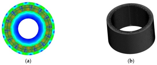
Figure 2.
Finite element model of DFIM: (a) electromagnetic simulation and (b) structural model.
The modal shapes of the stator core were calculated using FEA, as shown in Figure 3. The radial modes were identified as the dominant contributors to machine vibration.
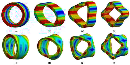
Figure 3.
Stator core modal shapes: (a) radial order 0; (b) radial order 2; (c) radial order 3; (d) radial order 4; (e) axial 0 order; (f) axial 2 order; (g) axial 3 order; and (h) axial 4 order.
Table 2 compares the natural frequencies obtained from finite element analysis and analytical models. The relatively large relative error in the low-order natural frequencies obtained from the finite element method and the analytical method is primarily due to their low absolute values. However, the absolute error remains small. From the perspective of motor vibration mechanism analysis, the analytical results still provide valuable guidance.
Table 2.
Natural frequencies of motor modal.
Large DFIMs used in VSPS typically employ multi-pole designs, which elevate the minimum non-zero force harmonics and render low-order modal effects negligible during normal operation. Under fault conditions such as rotor eccentricity or load imbalance, however, the spectral composition of radial electromagnetic forces changes significantly. The resulting low-order force waves then dominate the machine’s vibration characteristics.
3.2. Normal Condition
The DFIMs in VSPS power plants employ a high-capacity rotor-side converter (RSC) for excitation. The implemented three-level neutral-point-clamped (3L-NPC) converter topology demonstrates superior harmonic performance compared to conventional two-level configurations, yielding significantly reduced harmonic content in the excitation current. Figure 4 illustrates the excitation system configuration for the variable-speed pumped-storage application.
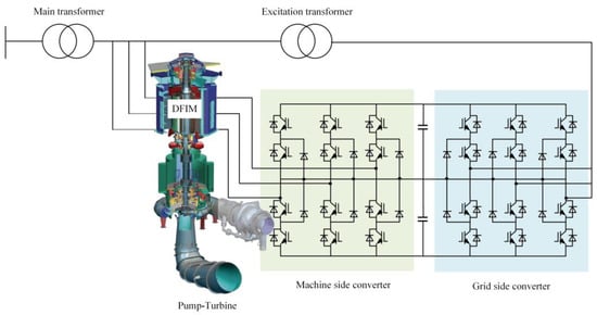
Figure 4.
Excitation system topology of VSPS power plant.
To account for harmonic currents in the converter-fed excitation supply, additional harmonic components at both the switching frequency and its integer multiples were injected into the rotor windings of the finite element model, superimposed on the fundamental sinusoidal current. The injected harmonics were set at 0.5% of the fundamental current amplitude. Figure 5 presents the air-gap flux density waveform under rated operating conditions along with its corresponding Fourier analysis results.
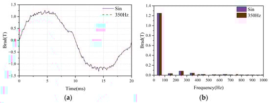
Figure 5.
Air-gap magnetic field of DFIM under different excitation methods: (a) waveform and (b) harmonic distribution.
As evident from Figure 5, the air-gap flux density waveforms exhibit minimal variation between the two excitation modes, standard sinusoidal current and harmonic-injected current, with nearly identical fundamental amplitudes. Under harmonic excitation, distinct 400 Hz and 750 Hz spectral components emerge in the flux density, corresponding to the converter’s switching frequency and its first integer multiple, respectively.
Figure 6 presents the two-dimensional Fourier decomposition results of radial electromagnetic force waves under both excitation schemes.
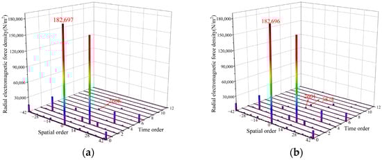
Figure 6.
2D Fourier decomposition results of radial electromagnetic force: (a) sinusoidal current and (b) contains harmonic current.
As shown in Figure 6, the dominant electromagnetic force waves exhibit comparable magnitudes under both excitation schemes. However, the harmonic-rich excitation current generates additional force wave components, notably, (0.7 fs), which originates from the interaction between the fundamental magnetic field produced by switching-frequency harmonics and that generated by the fundamental current. Furthermore, the analytical model’s theoretical predictions—including (14.2 fs), (28.4 fs), and (42.6 fs) force waves—are all experimentally observed, thereby validating the established analytical framework.
This study employs harmonic response analysis to investigate vibration characteristics in DFIM. The electromagnetic-structural coupling is implemented by applying radial electromagnetic force waves at stator tooth centers. Figure 7a compares the vibration acceleration spectra under different excitation methodologies. As shown in the figure, a prominent vibration peak occurs at 300 Hz, resulting from the proximity between the frequency of the 0th-order force wave (generated by interactions between 5th and 7th space harmonics of the stator and rotor) and the natural frequency (210 Hz) of the stator core’s breathing mode. Notably, the vibration amplitude under harmonic current excitation significantly exceeds that under pure sinusoidal excitation. Additionally, the harmonic-rich excitation induces a distinct vibration component at 350 Hz, attributed to the (0.7 fs) force produced by interactions between the harmonic-induced magnetic field and the fundamental magnetic field. These results conclusively demonstrate that harmonic components in the rotor excitation current amplify mechanical vibrations.
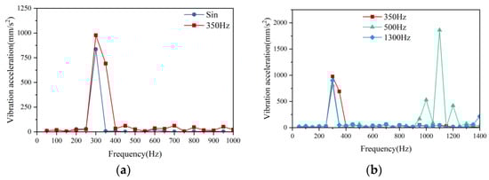
Figure 7.
Vibration acceleration distribution of DFIM: (a) sinusoidal excitation current and 350 Hz switching frequency excitation current and (b) 350 Hz, 500 Hz, and 1300 Hz switching frequency excitation currents.
This study systematically investigates the impact of rotor-side converter switching frequency on vibration characteristics in DFIMs. Comprehensive vibration tests were conducted across multiple switching frequencies, with the results presented in Figure 7b. The acceleration spectra reveal significant switching-frequency dependence, particularly showing maximum vibration at 1100 Hz when operating at 500 Hz switching frequency. This vibration peak is attributed to the 14th-order electromagnetic force wave generated by the interaction between the double switching-frequency current and the fundamental current. Resonance occurs as this force wave frequency precisely matches the natural frequency of the 14th-order structural mode. In contrast, at switching frequencies of 350 Hz and 1300 Hz, the resulting 14th-order electromagnetic force harmonics exhibit significant spectral separation from the natural frequencies, thereby effectively mitigating vibration excitation.
In conventional switching frequency selection for power electronic devices, higher frequencies are typically chosen to improve output waveform sinusoidal quality. However, this study reveals that such practice may significantly exacerbate machine vibrations. Our findings demonstrate that power electronic switching frequencies must be carefully selected to maintain vibration amplitudes within acceptable limits. Consequently, we propose the following rotor-side converter switching frequency selection criteria to ensure compliance with vibration requirements:
The most prominent advantage of VSPS lies in its flexible speed regulation capability, which enables rapid adjustment of the motor speed to accommodate varying head heights under different seasonal and hydrological conditions. This ensures that the unit consistently operates within its highest efficiency range. Consequently, it is essential to analyze the vibration characteristics of the motor under different rotational speed conditions. The distribution of vibration acceleration across different speeds is shown in Figure 8.
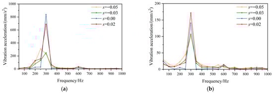
Figure 8.
The vibration acceleration of the DFIM at different speeds: (a) radial acceleration and (b) tangential acceleration.
Figure 8 reveals significant variations in the vibration acceleration distribution of the DFIM across different rotational speeds, with supersynchronous operation exhibiting higher amplitudes than subsynchronous conditions. This increase results from electromagnetic forces induced by the interaction of winding phase-belt harmonic fields under supersynchronous speeds, which excite frequencies closer to the natural frequency of the breathing mode. Notably, although the electromagnetic force frequency at s = 0.02 lies even closer to the natural frequency, the resulting vibration amplitude remains lower than that under the s = 0.00 condition. This suggests that both the amplitude and frequency of electromagnetic force waves collectively govern core vibration, highlighting the multifactorial nature of vibration excitation. The results confirm that the vibration behavior of DFIMs in VSPS applications varies substantially over the operating range.
3.3. Vibration Under Rotor Eccentricity
The vibration characteristics of DFIMs under rotor eccentricity conditions demonstrate significant correlation with both the fault type and the degree of eccentricity. This section presents a systematic investigation of radial electromagnetic forces and vibration responses for both static and dynamic eccentricity conditions across various eccentricity levels.
Figure 9 presents the radial electromagnetic forces and corresponding two-dimensional Fourier decomposition results under both static and dynamic eccentricity conditions at 30% eccentricity severity.
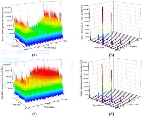
Figure 9.
Radial electromagnetic force distribution in DFIM under eccentricity condition: (a) waveform under static eccentricity; (b) harmonic distribution under static eccentricity; (c) waveform under dynamic eccentricity; and (d) harmonic distribution under dynamic eccentricity.
The radial electromagnetic force distribution clearly distinguishes static from dynamic eccentricity faults. Under static eccentricity, the minimum air-gap position remains fixed, resulting in persistent high- and low-amplitude zones in the force profile and no additional spectral components. In dynamic eccentricity, the minimum air gap rotates with the rotor, causing continuous spatial variation in force magnitude and location, along with additional frequency components. Two-dimensional Fourier decomposition further reveals ±1st-order sidebands around fundamental force waves under eccentricity—consistent with theoretical predictions and validating the analytical model.
Figure 10 illustrates the spatial distributions of radial electromagnetic forces under various eccentricity levels for both static and dynamic eccentricity conditions. Key observations include that (1) eccentricity attenuates the original 0th-order and 2pth-order force waves, with static eccentricity showing a negative correlation between the 2pth-order amplitude and eccentricity level, while dynamic eccentricity exhibits no consistent trend; and (2) additional 1st-order and (2p ± 1)th-order force waves emerge, whose amplitudes demonstrate positive proportionality with eccentricity severity.
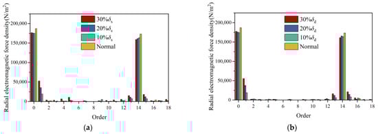
Figure 10.
Harmonic distribution of radial electromagnetic force under different eccentricity ratios: (a) static eccentricity and (b) dynamic eccentricity.
The vibration characteristics under rotor eccentricity conditions were investigated through harmonic response analysis, with the results presented in Figure 11.
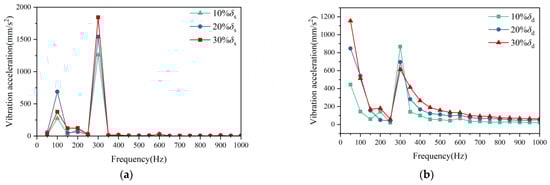
Figure 11.
Vibration acceleration distribution of DFIMs under different eccentricity ratios: (a) static eccentricity and (b) dynamic eccentricity.
Figure 10 demonstrates distinct vibration characteristics between static and dynamic eccentricity conditions. Under static eccentricity, the dominant vibration frequency occurs at 300 Hz, with this frequency increasing proportionally with eccentricity severity. In contrast, dynamic eccentricity produces prominent vibration at 50 Hz, the amplitude of which similarly escalates with eccentricity level. This fundamental difference stems from the generation of a 1st-order 50 Hz force wave in dynamic eccentricity, resulting from the interaction between the fundamental magnetic field and the (p ± 1)th-order harmonic field. Static eccentricity does not generate additional frequency components in the force wave spectrum; thus, no significant vibration is observed at 50 Hz. Eccentricity faults significantly deteriorate machine vibration performance, necessitating real-time rotor eccentricity monitoring during operation.
3.4. Vibration Under Asymmetric Loads
Load imbalance primarily manifests as three-phase current asymmetry in stator windings. For large machines with ungrounded neutral configurations, this condition exclusively produces negative-sequence currents without zero-sequence components. These negative-sequence currents distort the magnetic field distribution, thereby modifying the radial electromagnetic force. Figure 12 presents comparative radial force waveforms under balanced and unbalanced load conditions.
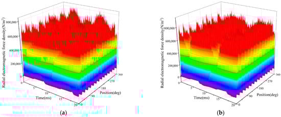
Figure 12.
Radial electromagnetic force waveform of DFIM: (a) load symmetry and (b) asymmetric load.
Under balanced load conditions, the radial electromagnetic force distribution remains uniform with time-invariant amplitude, consistent with characteristics of a circular rotating magnetic field. However, under unbalanced load operation, the force amplitude exhibits periodic temporal variations, reflecting the elliptical rotating field characteristics induced by negative-sequence currents.
To systematically assess the influence of stator negative-sequence current on electromagnetic force harmonics, three cases with negative-to-positive sequence current ratios of 3.23%, 6.25%, and 9.09% were analyzed. Figure 13 shows the Fourier decomposition results of the radial electromagnetic forces under these conditions. The negative-sequence current introduces new harmonic components, including force waves such as (ν ± η, ωs ± ωs) and (γ ± η, [s ± 1 + (1−s)/p] ωs). Among these, the force resulting from interaction with the positive-sequence magnetic field exhibits higher amplitude, which increases with the negative-sequence current ratio. High-frequency electromagnetic forces have low amplitudes and lie far from the motor’s natural frequency, resulting in a negligible vibration impact. In contrast, the low-frequency forces feature both lower orders and higher amplitudes, significantly threatening motor safety and, thus, requiring prioritized attention.
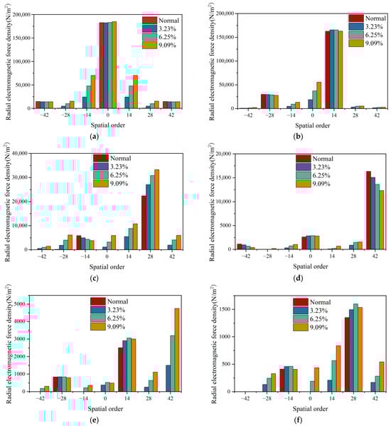
Figure 13.
Harmonic spectra of electromagnetic force density in DFIM under different operating conditions: (a) 0 fs; (b) 2 fs; (c) 4 fs; (d) 6 fs; (e) 8 fs; and (f) 10 fs.
The vibration characteristics of the motor under different load imbalance levels were analyzed using harmonic response analysis, with the results shown in Figure 14. Compared with the vibration acceleration distribution under balanced load conditions, the motor exhibits pronounced low-frequency vibrations (e.g., at 100 Hz and 200 Hz) under load imbalance, with the amplitudes increasing proportionally to the degree of imbalance.
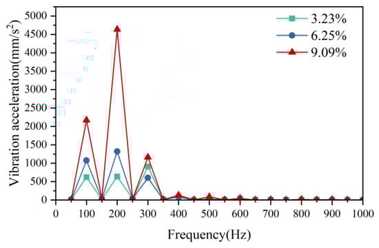
Figure 14.
Vibration acceleration distribution of DFIM under load imbalance condition.
The observed emergent vibration frequencies exhibit a deterministic correlation with negative-sequence current components. Specifically, the fundamental-wave magnetic field generated by stator-winding negative-sequence current interacts with its positive-sequence counterpart, inducing (0, 100 Hz) electromagnetic force waves that directly excite breathing-mode vibrations in the motor structure. More critically, the fifth spatial-harmonic magnetic field components from both stator negative-sequence current and rotor excitation current interact to produce (0, 200 Hz) force waves. This frequency precisely coincides with the intrinsic breathing-mode natural frequency, thereby establishing a resonant condition. The presence of negative-sequence current substantially increases the risk of mechanical resonance and deteriorates vibration performance in DFIMs. This necessitates the real-time monitoring of load imbalance severity and immediate mitigation measures when thresholds are exceeded.
4. Experimental Verification
Considering the extended manufacturing cycles and experimental validation challenges associated with large-scale electrical machines, the study employs a 10 MW DFIM as the research subject, with vibration tests conducted to verify the accuracy of finite element simulation results. The main parameters of the test prototype are listed in Table 3. Figure 15 shows the constructed test platform and vibration monitoring system.
Table 3.
Main parameters of the 10MW DFIM.
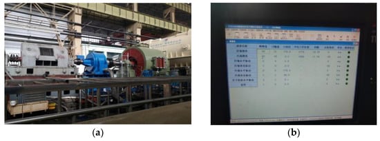
Figure 15.
Vibration test system: (a) test platform and (b) vibration monitoring interface.
The testing procedure strictly adhered to the Chinese national standard JB/T 10392-2013 [34]. Vibration signals from the stator core and frame were acquired in real-time using velocity sensors, amplified through voltage amplifiers, and processed by a signal analyzer for filtering, integration, and time-domain analysis to determine the vibration amplitudes of the stator core and frame. The experimental and FEA results of vibration displacement under normal operating conditions are presented in Table 4.
Table 4.
Vibration test results of the 10 MW DFIM.
The finite element simulation results exhibit lower values compared to experimental measurements, primarily due to differences in damping modeling and the omission of rotating rotor components in the structural analysis. Nevertheless, the deviations remain within acceptable limits, demonstrating the validity of the vibration analysis methodology adopted in this study.
5. Conclusions
This paper systematically investigates the vibration characteristics of DFIMs in VSPS power plants through theoretical analysis and finite element simulation, covering special operating conditions including rotor eccentricity and load imbalance. Compared with small-capacity DFIMs used in wind power generation, large-capacity machines in pumped storage systems exhibit unique vibration challenges: Their larger physical dimensions result in lower natural frequencies of structural modes, while the limited switching frequencies of high-power converters create excitation sources in similar frequency ranges, significantly increasing resonance risks. To address this, we propose an optimized switching frequency selection range for rotor-side converters to effectively avoid resonant conditions.
The vibration performance of DFIMs deteriorates under rotor eccentricity conditions. Static eccentricity primarily amplifies vibration amplitudes at existing characteristic frequencies, whereas dynamic eccentricity introduces additional low-frequency vibration components dominated by lower-order modes. Furthermore, negative-sequence currents induced by load imbalance increase low-frequency harmonic components in radial electromagnetic forces, substantially elevating resonance risks. The vibration acceleration spectra obtained under these abnormal operating conditions can be implemented in protection relay systems as auxiliary criteria for circuit breaker tripping decisions, thereby enhancing machine safety.
Author Contributions
Conceptualization, H.K. and Y.M.; methodology, L.L.; software, H.K.; validation, L.Z., Y.M. and L.L.; formal analysis, F.H.; investigation, F.H.; resources, Y.M. All authors have read and agreed to the published version of the manuscript.
Funding
This research was funded by the project “Research on Grid-Forming Energy Storage System Technology Based on Multi-Phase and Multi-Port Motor” of CSG PGC Energy Storage Research Insitute, grant number STKJXM20240075.
Data Availability Statement
The original contributions presented in this study are included in the article. Further inquiries can be directed to the corresponding author.
Conflicts of Interest
The authors declare no conflicts of interest.
References
- Sun, L.; Ma, Y.; Wang, J.; Kang, H.; Li, Z.; Zhou, L. An Accurate Nonlinear Model for Design of DFIGMs Considering Saturation Effects Based on Subdomain Method and Morphology. IEEE Trans. Transp. Electrif. 2025, 11, 7773–7785. [Google Scholar] [CrossRef]
- Chen, Y.; Xu, W.; Liu, Y.; Bao, Z.; Mao, Z.; Rashad, E.M. Modeling and Transient Response Analysis of Doubly-Fed Variable Speed Pumped Storage Unit in Pumping Mode. IEEE Trans. Ind. Electron. 2023, 70, 9935–9947. [Google Scholar] [CrossRef]
- Chen, Y.; Deng, C.; Zhao, Y. Coordination Control Between Excitation and Hydraulic System During Mode Conversion of Vari-able Speed Pumped Storage Unit. IEEE Trans. Power Electron. 2021, 36, 10171–10185. [Google Scholar] [CrossRef]
- Traxler-Samek, G.; Lugand, T.; Uemori, M. Vibrational Forces in Salient Pole Synchronous Machines Considering Tooth Ripple Effects. IEEE Trans. Ind. Electron. 2012, 59, 2258–2266. [Google Scholar] [CrossRef]
- Liu, L.; Li, Z.; Kang, H.; Xiao, Y.; Sun, L.; Zhao, H.; Zhu, Z.; Ma, Y. Review of surrogate model assisted multi-objective design optimization of electrical machines: New opportunities and challenges. Renew. Sustain. Energy Rev. 2025, 215, 115609. [Google Scholar] [CrossRef]
- Liu, L.; Yao, H.; Di, P.; Qin, Y.; Ma, Y.; Alkahtani, M. Region of Attraction Estimation for Power Systems with Multiple Integrated DFIG-Based Wind Turbines. IEEE Trans. Sustain. Energy 2025, in press. [CrossRef]
- Desingu, K.; Selvaraj, R.; Chelliah, T.R.; Khare, D. Effective Utilization of Parallel-Connected Megawatt Three-Level Back-to-Back Power Converters in Variable Speed Pumped Storage Units. IEEE Trans. Ind. Appl. 2019, 55, 6414–6426. [Google Scholar] [CrossRef]
- Joseph, A.; Chelliah, T.R. A Review of Power Electronic Converters for Variable Speed Pumped Storage Plants: Configurations, Operational Challenges, and Future Scopes. IEEE J. Emerg. Sel. Top. Power Electron. 2018, 6, 103–119. [Google Scholar] [CrossRef]
- Wang, C.; Wu, Z.; Ren, C.; An, Z.; Gui, Z.; Lu, W. Electromagnetic Force Characteristics of Doubly-Fed Induction Machines Considering Harmonics from Rotor-Side Converters. IEEE Trans. Ind. Appl. 2025, in press. [CrossRef]
- Ali, J.; Chelliah, T.R.; Agarwal, P. Estimation of Stator Vibration in DFIM Under Various Types of Rotor Excitation. IEEE Trans. Ind. Appl. 2023, 59, 4095–4107. [Google Scholar] [CrossRef]
- Ali, J.; Chelliah, T.R.; Agarwal, P. Influence of Rotor Side Converter on Electromagnetic Vibration in Asynchronous Hydrogen-erator. IEEE J. Emerg. Sel. Top. Power Electron. 2024, 12, 2226–2233. [Google Scholar] [CrossRef]
- Gui, Z.; Lu, W.; Zhao, B.; Wang, C.; Xu, G.; Zhao, H. Analytical Calculation of Electromagnetic Force of VSPS Considering Har-monic supply in Rotor Converters. In Proceedings of the IEEE Energy Conversion Congress and Exposition (ECCE), Nashville, TN, USA, 29 October–2 November 2023. [Google Scholar]
- Michon, M.; Holehouse, R.C.; Atallah, K.; Johnstone, G. Effect of Rotor Eccentricity in Large Synchronous Machines. IEEE Trans. Magn. 2014, 50, 8700404. [Google Scholar] [CrossRef]
- Kim, D.; Kim, H.; Hong, J.; Park, C. Estimation of Acoustic Noise and Vibration in an Induction Machine Considering Rotor Ec-centricity. IEEE Trans. Magn. 2014, 50, 857–860. [Google Scholar] [CrossRef]
- Wang, D.; Wang, X.; Wang, B.; Nie, J.; Li, J.; Wang, X. Dynamic Eccentricity Impact on Electromagnetic Vibration and Acoustic Noise of Interior Permanent Magnet Synchronous Motors With Different Numbers of Parallel Branches. IEEE Trans. Transp. Electrif. 2025, 11, 3337–3348. [Google Scholar] [CrossRef]
- Ito, F.; Takeuchi, K.; Kotsugai, T.; Matsushita, M. A Study on Asymmetry of Electromagnetic Force Modes of Permanent Magnet Synchronous Motors With Rotor Eccentricity. IEEE Trans. Magn. 2021, 57, 8103306. [Google Scholar] [CrossRef]
- Kang, H.; Ma, Y.; Xie, T.; Sun, L.; Li, Z.; He, R. Analysis of Influence of Rotor Eccentricity in Double Fed Induction Machine. In Proceedings of the International Conference on Power and Energy Applications (ICPEA), Weihai, China, 24–26 November 2023. [Google Scholar]
- Kang, H.; Wang, J.; Liu, L.; Sun, L.; Li, Z.; Zhou, L. Analysis and Optimization of Unbalanced Magnetic Pull for Eccentric Doubly-Fed Induction Motor. In Proceedings of the International Conference on Electrical Machines (ICEM), Torino, Italy, 1–4 September 2024. [Google Scholar]
- Dorrell, D.G.; Salah, A.; Guo, Y. The Detection and Suppression of Unbalanced Magnetic Pull in Wound Rotor Induction Motors Using Pole-Specific Search Coils and Auxiliary Windings. IEEE Trans. Ind. Appl. 2017, 53, 2066–2076. [Google Scholar] [CrossRef]
- Shanbhag, V.V.; Kandukuri, S.T.; Olimstad, G.; Schlanbusch, R. Predictive maintenance of critical components in hydro-electric turbines: A review. IEEE Sens. J. 2025, in presss.
- Hernández, E.; Madrigal, M. A Step Forward in the Modeling of the Doubly-fed Induction Machine for Harmonic Analysis. IEEE Trans. Energy Convers. 2014, 29, 149–157. [Google Scholar] [CrossRef]
- Dymond, J.H.; Stranges, N. Operation on Unbalanced Voltage: One Motor’s Experience and More. IEEE Trans. Ind. Appl. 2007, 43, 829–837. [Google Scholar] [CrossRef]
- Shu, H.; Li, C.; Dai, Y.; Tang, Y.; Han, Y. An Adaptive Single-phase Reclosing Technique for Wind Farm Transmission Lines Based on SOD Transformation of CVT Secondary Voltage. Prot. Control Mod. Power Syst. 2025, 10, 58–71. [Google Scholar] [CrossRef]
- Xu, G.; Wang, Z.; Zhou, J.; Li, Z.; Zhan, Y.; Zhao, H. Rotor Loss and Thermal Analysis of Synchronous Condenser Under Single-Phase Short-Circuit Fault in the Transmission Line. IEEE Trans. Energy Convers. 2022, 37, 274–285. [Google Scholar] [CrossRef]
- Campbell, M.; Arce, G. Effect of Motor Voltage Unbalance on Motor Vibration: Test and Evaluation. IEEE Trans. Ind. Appl. 2018, 54, 905–911. [Google Scholar] [CrossRef]
- Donolo, P.; Pezzani, C.; Bossio, G.; Angelo, C.; Donolo, M. Vibration Magnitude Analysis on Induction Motors of Different Effi-ciency Classes Due to Voltage Unbalance. IEEE Trans. Ind. Appl. 2023, 59, 2913–2918. [Google Scholar] [CrossRef]
- Zhang, G.; Wu, Y.; Zhang, Z.; Chen, C.; Hu, L. Electromagnetic force and vibration characteristics of generator stator under asymmetric load conditions. Electr. Mach. Control 2024, 8, 10–20. [Google Scholar]
- GE, B.; Jiang, C.; Lv, P.; Tao, D.; Lin, P.; Yin, J.; Zhao, H. Analysis of rotor dynamic electromagnetic force in large nuclear turbines under open-phase operation condition. Electr. Mach. Control 2021, 25, 26–35. [Google Scholar]
- Liang, Y.; Yao, Q. Analysis and calculation of electromagnetic force on damper windings for 1000MW hydro-generator. In Proceedings of the International Conference on Electrical Machines and Systems (ICEMS), Beijing, China, 20–23 August 2011. [Google Scholar]
- Sun, L.; Kang, H.; Wang, J.; Li, Z.; Liu, J.; Ma, Y. Analytical Model and Topology Optimization of Doubly-Fed Induction Generator. CES Trans. Electr. Mach. Syst. 2024, 8, 162–169. [Google Scholar] [CrossRef]
- CHEN, L.; LE, Z.; LIU, Y. Technical Characteristics and Research Framework of Large AC Excitation Variable Speed Pumped Storage Units. Power Syst. Technol. 2024, 48, 2366–2375. [Google Scholar]
- Du, J.; Li, Y. Analysis on the Variation Laws of Electromagnetic Force Wave and Vibration Response of Squirrel-Cage Induction Motor under Rotor Eccentricity. Electronics 2023, 12, 1295. [Google Scholar] [CrossRef]
- Xing, Z.; Wang, X.; Zhao, W.; Sun, L.; Niu, N. Calculation Method for Natural Frequencies of Stator of Permanent Magnet Synchronous Motors Based on Three-Dimensional Elastic Theory. IEEE Trans. Energy Convers. 2021, 36, 755–766. [Google Scholar] [CrossRef]
- JB/T 10392-2013; Test Methods and Evaluation for Dynamic Characteristics and Vibration of Stator Frames and Cores in Turbine-Type Generators. Ministry of Industry and Information Technology of China: Beijing, China, 2013.


Disclaimer/Publisher’s Note: The statements, opinions and data contained in all publications are solely those of the individual author(s) and contributor(s) and not of MDPI and/or the editor(s). MDPI and/or the editor(s) disclaim responsibility for any injury to people or property resulting from any ideas, methods, instructions or products referred to in the content. |
© 2025 by the authors. Licensee MDPI, Basel, Switzerland. This article is an open access article distributed under the terms and conditions of the Creative Commons Attribution (CC BY) license (https://creativecommons.org/licenses/by/4.0/).