Article

Experimental Innovative Prototype Solution for a Specialized Handling Trolley for Sampling Devices

by
Roman Čierťažský
,
Mária Vargovská
and
Elena Pivarčiová
*
Department of Manufacturing and Automation Technology, Faculty of Technology, Technical University in Zvolen, T.G. Masaryka 2117/24, 96001 Zvolen, Slovakia
*
Author to whom correspondence should be addressed.
Machines 2025, 13(9), 775; https://doi.org/10.3390/machines13090775
Submission received: 8 August 2025 / Revised: 25 August 2025 / Accepted: 27 August 2025 / Published: 29 August 2025
(This article belongs to the Section Machine Design and Theory)

Abstract

The aim of this paper is to describe the design and construction of a handling trolley developed to simplify material handling processes in production areas as part of a company’s innovation strategy. Effective handling in any production process improves both quality and efficiency. Due to workplace changes, it was necessary to respond promptly and effectively. Based on this requirement, a handling trolley was designed to securely and efficiently hold clamping fixtures and transport them between workstations. The incorporation of new design parameters enabled the development of an innovative trolley that meets all operational requirements. The proposed trolley can be operated by a single worker and ensures safe, stable, and efficient transport of clamping fixtures. Its robust frame structure combined with a movable clamping unit provides a simple yet reliable solution for handling sampling devices.

1. Introduction

Automation has become an integral part of modern manufacturing processes. It covers the handling and transport of products, replacing manual operations with manipulators and robots. This process consists of several stages, most of which are automated using specialized equipment [1]. In recent years, elements of artificial intelligence have been increasingly integrated into these systems [2,3] with the aim of increasing production efficiency and flexibility. Nevertheless, human labor remains indispensable in many manufacturing tasks.
All production, processing, and handling equipment is designed with efficiency and safety in mind. The main source of creation and implementation of any advanced technology in its individual stages of development in the production process is rationalization [4], and this applies to the design of all equipment, especially prototype equipment. Since machine design is highly diverse depending on the requirements for their use in operation, as well as their price [5], it is necessary to approach each solution individually.
The innovative design itself concerns a handling trolley. Handling equipment is used to move objects from one place to another (e.g., between workplaces, between a loading ramp and a storage area). They are divided into subgroups of conveyors, cranes, and transport trolleys. Transport trolleys are trolleys that are not permitted to travel on public roads, unlike commercial vehicles. They are used to move cargo along various (horizontal) tracks without restrictions on the area covered (unlimited space). If the trolleys are equipped with a lifting mechanism, they also provide vertical movement. They are used when there is insufficient (or interrupted) material flow where it is disadvantageous to use conveyors. They provide greater flexibility of movement than conveyors and cranes [6].
With the arrival of new and more complex cylinder head designs, the entire manufacturing and handling process has changed, and the design of sand cores has also changed towards greater core complexity, and, above all, an insufficient number of contact surfaces for securing the core with clamping devices. As a result of these changes, the clamping fixtures underwent an innovation process. There was a shift from the concept of a “frame welded from angle irons with screwed-on clamping modules, so-called cushions” to devices containing various pneumatic cylinders or fingers (grippers). These are mounted on an aluminum frame or on a plate, which also serves to reinforce the device. This results in an increase in the dimensions of the device, but mainly in an increase in its weight. From the former maximum of 40 kg in the old concepts, the new ones weigh from 60 to 80 kg. Another change concerns the length. From the original maximum length of 1090 mm due to the height of the stands, the height was set to 1160 mm after their modification. The stands were modified by adding a 310 mm extension to create a reserve in case a longer clamping fixture is needed. The greater weight of the clamping fixtures and the greater clearance height of the modified stand result in poorer handling of the devices. This applies both when transferring the device to another workplace and when inserting or removing the device from the stand. This is where one of the problems arose, namely that such workplaces usually have a single operator, and therefore it is always necessary to call another worker to perform this task.
Another problem that arose was that the clamping fixture is not equipped with handles or holes for attachment, and therefore it was usually attached by parts that could be damaged during transport and loading or unloading from the rack. Based on theoretical knowledge and input parameters, it was possible to create a design that stabilized the clamping fixture and was able to ensure safe transport of the clamping fixture from the removal point to the destination node. We also agree with Leggieri et al., who “developed an online risk assessment system for load handling that achieved a relative error of <3% compared to traditional observation methods”. Other authors have also pointed out that ergonomically optimized trolleys significantly reduce the physical strain of handling large-format materials [7,8]. The choice of materials played an important role in the design. Due to the improved weldability of the trolley structure, the material S235 JRH/E235 according to STN EN 10219-1 [9] and STN EN 10305-3 [10] was selected for the angle sections; quality standard: STN EN 10025-2 [11]; in the basic state. Minimum yield strength Re = 235 MPa, notch toughness 27 J at a temperature of +20 °C (JR) with increased resistance to aging. The material S355J2 + N according to STN EN 10025-2 [11] was selected for the sheet metal parts, in the basic state, normalized. Minimum yield strength Re = 355 MPa, notch toughness 27 J at a test temperature of −20 °C (J2), with increased resistance to aging. Without the addition of +N or +A, the delivery status is "as delivered". For a better understanding of the designations we use to characterize the materials defined in the previous text, it is important to note that the individual selected designations described are steel designations, and the individual material characteristics are hidden under the individual letters and numbers [12]. The JR and J2 designations express the material characteristics of steel according to European standards EN 10025-2. JR denotes steel with the ability to absorb 27 J in an impact test at a temperature of +20 °C, while J2 denotes 27 J at −20 °C, reflecting the higher toughness of the material at low temperatures [12]. In addition to the already defined design requirements, it was also necessary to take into account the effects of internal forces, based on our knowledge of the following basic types of stress: simple tension (compression), the only internal force is the axial force N; simple shear, the only internal force is the transverse force 𝑇; simple bending, the only internal force is the bending moment 𝑀𝑜; and simple torsion, the only internal force is the torsional moment 𝑀k [13]. All this and more had to be taken into account in the design. The main risks which may arise after assembling interchangeable equipment to a FLT are related to the loss of stability of the assembly [14]. This applies not only to forklifts, but also to any equipment used to handle objects. It is therefore appropriate to state, and we can agree with other authors, that this innovation uses multiple engineering skills, such as conceptual design, formal analysis, and experimental verification, to determine and develop the best possible design for the cart [15]. Numerous studies have examined the resistance force during the initial and sustained phases of various wheeled devices, such as wheelchairs [16], hospital beds [17], and airplane food carts [18]. These studies showed that the highest forces are exerted precisely during the initial phase of movement [19]. It was found that rolling resistance is significantly higher on soft surfaces, such as carpet, compared to hard surfaces, such as tiles or concrete [16]. Factors influencing rolling resistance include the load, which has a linear relationship with resistance, and the wheel diameter, with which it has an indirect relationship [20]. Although few studies have focused on measuring the force transmitted by the wheel to the ground, for example, from a wheelchair [21] or a manual cart [22], there are methods, such as a low-cost testing device, which can monitor and measure the forces generated by the contact between the wheel and the ground [21]. This body of existing research provided a theoretical basis for the design of the cart, combining principles of load dynamics and human biomechanics from various fields with specific industrial applications.
In our solution, we focus primarily on the safety, stability, and load-bearing capacity of this innovative solution. Here, we agree with other authors who state that “The criteria for selecting the proposed solution are determined by the technical and economic parameters that the designed prototype must achieve” [5,23]. Another important fact is the authors’ claim that there is up to a 35% drop in productivity and an increased risk of injury when handling worn-out trolleys, and that optimized motion control in handling systems increases handling accuracy and helps reduce the risk of operator injury [24,25]. The authors of the article (Anggono et al.) report that problems are associated with non-ergonomic carts, with back pain in workers due to forces during pushing and pulling. Their study showed that the redesigned cart with ergonomic benefits contributed to body positioning [26]. If we wanted to point out design elements such as trolleys wheels and their selection, we would agree with the authors who “present a new approach based on the calibration of pushing forces between the wheel type and the floor surface, with the average deviation of the model from the experiment being only 5.1%” [27].
Ergonomic design of handling devices has been proven to significantly reduce operator strain and improve usability. The authors of [28] demonstrated that properly designed sheet metal handling trolleys lowered muscle activity and increased worker satisfaction compared to conventional hydraulic devices. The authors of [29] developed a six-wheeled trolley capable of transporting 100 kg loads, which was adapted to workers’ anthropometric dimensions and capable of overcoming uneven terrain.
Other studies highlighted the need for integrating ergonomics into cart design. For example, the authors of [30] applied the OWAS and Ergonomic Function Deployment methods to redesign a food service trolley, achieving a clear reduction in musculoskeletal disorder risks. In industrial contexts, redesigning material handling systems using ergonomic approaches has shown measurable improvements in posture and reduced back pain risk [30].
Recent approaches also emphasize modeling of pushing and pulling forces. The authors of [27] introduced a methodology to optimize manual cart design by calculating corrective forces, aiming to minimize musculoskeletal injuries.
Experimental studies such as the development of a trolley-lifter for sheet metal demonstrated increased efficiency and improved working posture compared to traditional manual handling [31]. These findings support the practical relevance of integrating ergonomic analysis into prototype design.
The objective of this study was to design, construct, and validate a specialized handling trolley for transporting heavy clamping fixtures. The prototype was developed to ensure safety, stability, and ergonomic usability, with a focus on reducing manpower requirements and improving handling efficiency.

2. Materials and Methods

The overall research methodology followed a structured workflow: (I) definition of requirements based on fixture dimensions and weight; (II) conceptual design of the trolley; (III) analytical calculations of internal forces and stresses; (IV) verification through numerical simulation in Creo Simulate; (V) prototype manufacturing; (VI) experimental validation under real production conditions. This workflow is illustrated in Figure 1.
The design itself was approached systematically, from the definition of initial requirements, through the selection of materials, to the use of analytical mathematical methods, the results of which were compared with simulations from the Creo Simulate program.
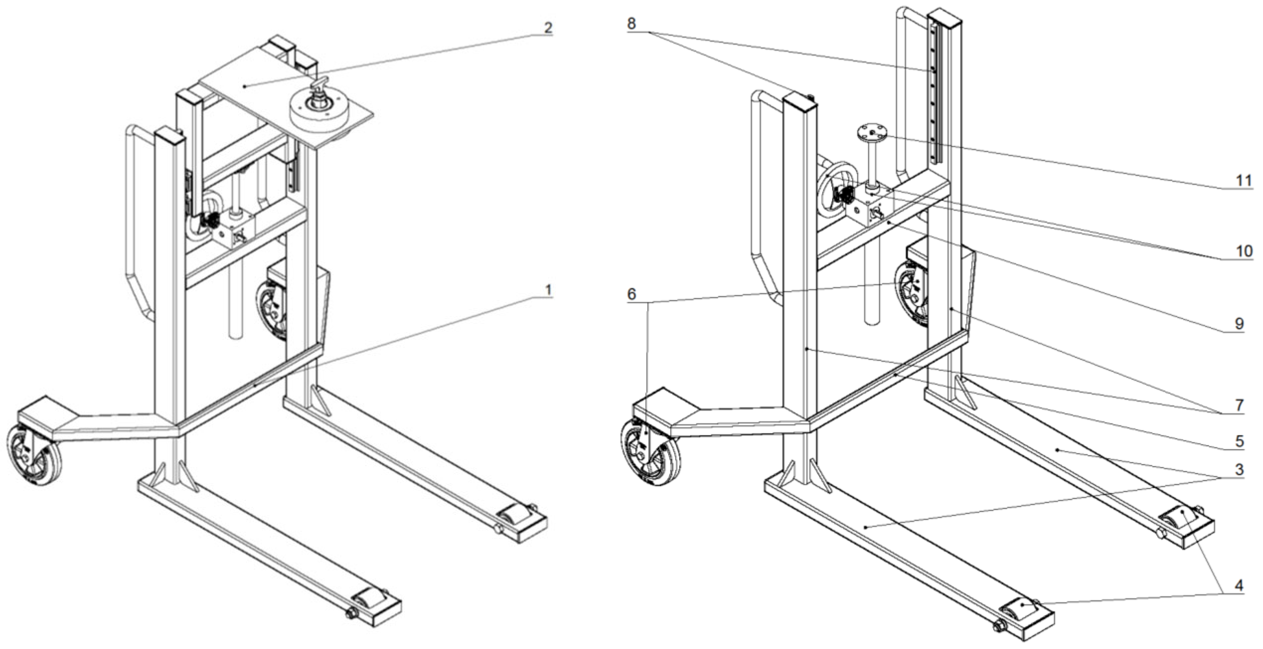
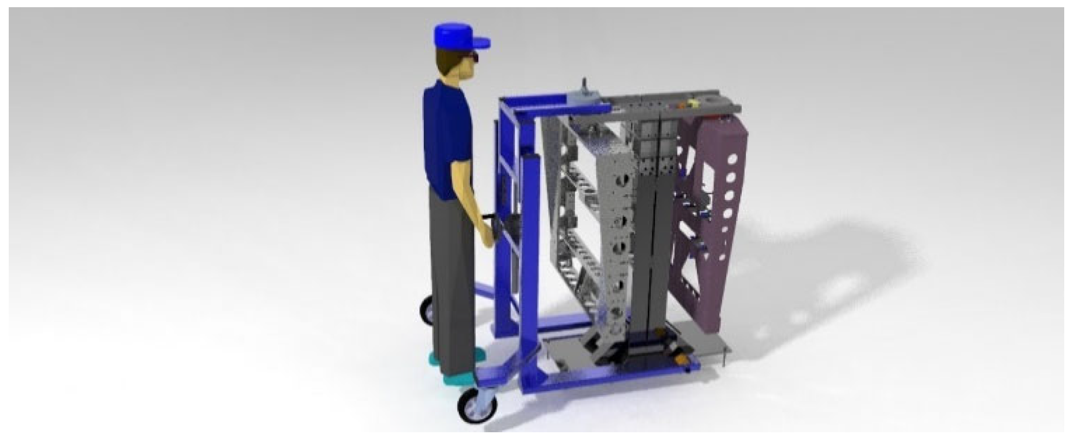
Figure 2 aptly illustrates the basic concept of the proposed trolley, where the fixed and moving parts are clearly separated. The handling trolley transports the fixtures by clamping them to the detachable part of the tool changer. The vertical movement of the movable part is performed by a screw jack. This solution has industrial applications, particularly in mechanical engineering and the automotive industry [32].

2.1. Conceptual Design and Definition of Input Parameters

The starting point was the requirement to design and construct a handling trolley intended for transporting material in production areas. The trolley was designed with a maximum load capacity of 205 kg, matching the capacity of industrial robots used in the workplace. This parameter is identical to the load capacity of the industrial robots for which the trolley was designed. This data fundamentally influenced all subsequent decisions regarding the choice of material and the dimensioning of the load-bearing elements.
The dimensional specifications were determined with an emphasis on ergonomics and practical usability in production areas. The size of the structure was designed with regard to the maximum possible dimensions of the clamping fixture of 1200 mm × 1200 mm, which provides sufficient space for handling standardized containers and materials. The overall external dimensions of the trolley were chosen to ensure easy maneuverability while meeting ergonomic parameters for the operator.
The entire design process, from initial sketches through the creation of detailed 3D models of individual components and assemblies to the generation of final production documentation, was carried out in the Creo parametric CAD 9.0 (Computer-Aided Design) software environment. This integrated approach enabled the effective linking of the design phase with the subsequent strength analysis phase.

2.2. Material Solution and Its Justification

The choice of materials was guided by the principle of achieving the required mechanical properties while optimizing production costs and technological feasibility. For the main supporting structure, consisting of a frame made of closed square profiles (hollow structural section (HSS)), non-alloy structural steel of class S235JR was selected. This material is the standard in general engineering and steel structures due to its advantageous combination of mechanical properties, good weldability, and low price.
For the sheet metal parts of the trolley, which were expected to experience higher stress concentrations based on preliminary analysis, higher strength structural steel of class S355 was selected. This approach, where a more powerful (and more expensive) material is used locally only in critically stressed areas while the largest part of the structure in terms of volume is made of a more economical variant, is a practical application of value engineering. The aim is to achieve the required functional reliability without unnecessarily increasing the cost of the entire structure. However, this approach introduces a certain degree of complexity into the manufacturing process, as it requires the management of two different materials and increases the risk of confusion during production which requires thorough quality control.

2.3. Calculation of Structural Forces

In this step, the basic external forces acting on the trolley were determined. The masses of individual components (fixture, clamping device, and bearings) were converted into their equivalent gravitational forces using 𝐹 = m·g. By summing these contributions, the total operating load of 3075.5 N was obtained, representing the maximum vertical force acting on the structure. This result served as the starting parameter for subsequent static calculations and simulations.
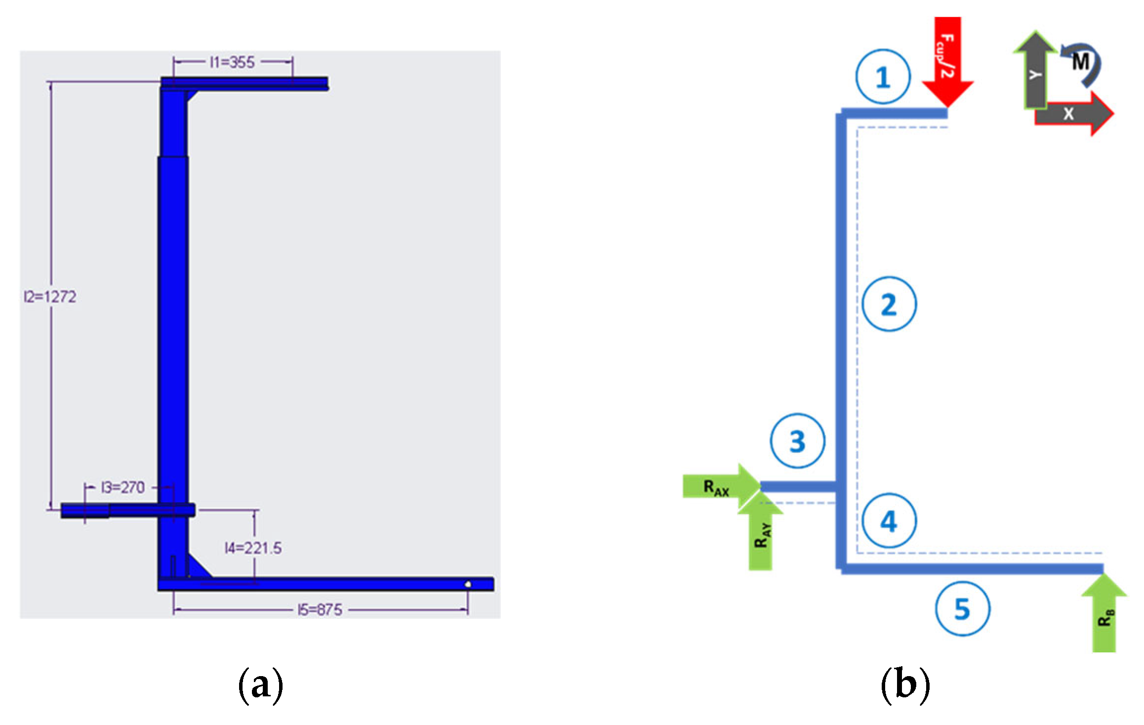
To calculate the force effects, it was first necessary to calculate the total load on the trolley (Figure 3a).

2.3.1. Total Load of the Trolley

  • Load from nominal load:
𝐹𝑏 = 𝑚𝑏 · 𝑔 = 300 · 9.81 = 2943 N
where
𝑚b = 300 [kg] nominal load weight,
𝑔 = 9.81 [m·s−2] gravitational acceleration.
  • Load from clamping device:
𝐹𝑢 = 𝑚𝑢 · 𝑔 = 11.310 · 9.81 = 110.950 N
where
mu = 11.310 [kg] weight of the clamping device.
  • Load from the bearing:
𝐹loz= 𝑚loz · 𝑔 = 2.2 · 9.81 = 21.580 N
where
𝑚loz = 2.2 [kg] bearing weight.
  • Total load capacity of the trolley:
𝐹Cup = 𝐹𝑏 + 𝐹𝑢 + 𝐹𝑙𝑜𝑧 = 2943 + 110.950 + 21.580 = 3075.500 N
The calculations performed in Equations (1)–(4) define the basic external load acting on the structure of the handling trolley. The calculated load is from the nominal load (in our case, the fixture), the clamping fixture itself, and the bearing. The aim of these calculations was to determine the value of the resulting force transmitted to the frame of the structure. The resulting force of 3075.5 N represents the maximum operating load that the trolley must safely carry.

2.3.2. Calculation of External and Internal Force Effects

These calculations were performed using the theory of broken beams. Figure 3 shows the basic dimensions of the structural frame and its division into sections—beams. The figure with sections also shows the relaxed structure with the corresponding 𝑅𝐴𝑌 and 𝑅𝐵 reactions acting at the point of wheel mounting on the trolley. The force is calculated as half, since we only consider one part of the structure, given that the entire structure is symmetrical. This figure is important for understanding the calculations of force effects. The FCup force itself acts at the point of attachment of the clamping device, 355 mm from the center of the vertical structure (Table 1). Additionally, the dimensions of each numbered structure in Figure 3b are also listed in Table 1.
To improve the clarity of the internal force calculations, it is first necessary to outline the applied methodology. The structure was divided into individual sections (beams), and for each section the equilibrium equations were formulated. From these, we determined the reaction forces at the supports, then calculated shear and axial forces, and finally the bending moments. This procedure follows the standard bar statics method and allows us to trace step by step how the applied load is transferred into individual profiles. The obtained results form the basis for cross-sectional design and material strength verification.
  • Calculation of external reactions on the structure:
Σ𝐹𝑖𝑥 = 0, 𝑅𝐴𝑋 = 0 N
Σ𝐹𝑖𝑦 = 0, −𝐹 + 𝑅𝐴𝑌 + R𝐵 = 0
−1357.750 + 616.620 + 𝑅𝐵 = 0
𝑅𝐵 = 741.130 N
Σ𝑀𝑖𝐵 = 0, 𝐹(𝑙5−𝑙1) − 𝑅𝐴𝑌(𝑙3 + 𝑙5) = 0
1357.750 · (0.875 − 0.355) − 𝑅𝐴𝑌(0.270 + 0.875) = 0
𝑅𝐴𝑌 = 616.620 N
Based on static equilibrium Equations (5)–(7), we determined the reaction forces at the points where the trolley wheels are mounted (𝑅𝐴𝑌 and 𝑅𝐵). These values are essential for dimensioning the load-bearing rods, as they determine the load that each wheel and the associated part of the frame will have to carry. The reactions, whose calculated values are 𝑅𝐴𝑌 = 616.620 N and 𝑅𝐵 = 741.130 N, ensure the equilibrium of the system under full load.
Calculation of internal forces acting on individual sections:
Based on the internal forces acting, we can identify the following basic types of stress, which are discussed in the following text in individual sections:
-
Simple tension (pressure)—the only internal force is the axial force 𝑁;
-
Simple shear—the only internal force is the transverse force 𝑇;
-
Simple bending—the only internal force is the bending moment 𝑀𝑜;
-
Simple torsion—the only internal force is the torsional moment 𝑀k [13].
  • Solution for Section 1: 0 ≤ x1l1
Axial (normal) force 𝑁:
𝑁1 = 0 N
Transverse (shear) force 𝑇:
𝑇1 = 𝐹
T1 = 1357.75 N
Bending moment 𝑀:
𝑀1 = −𝐹 · 𝑥1
𝑀1(0) = −1357.75 · 0 = 0 Nm
𝑀1(𝑙1) = −1357.75 · 0.335 = −482.001 Nm
For Section 1, the axial force 𝑁1, shear force T1, and bending moment 𝑀1 were calculated. The most significant result is the bending moment 𝑀1 = −482 Nm, which defines the stiffness requirements for this part of the frame. This value was later used to select the appropriate cross-section. These results show that Section 1 experiences the highest bending stress, making this section critical for dimensioning the structural profile.
2.
Solution for Section 2: 0 ≤ x2l2
𝑁2 = −𝐹
𝑁2 = − 1357.75 N
𝑇2 = 0 N
𝑀2 = −𝐹 · 𝑙1
𝑀2 = −1357.75 · 0.335 = −482.001 Nm
In Section 2, the internal forces were determined, showing lower bending moments compared to Section 1. While not critical for the design, this section confirms the load continuity and contributes to overall frame stability. We can also say that Section 2 shows the same bending moment value as Section 1, but due to the different nature of internal forces it is important to verify the effect of the axial force. This ensures that the entire frame remains in equilibrium.
3.
Solution for Section 3: 0 ≤ x3l3
𝑁3 = 0 N
𝑇3 = 𝑅𝐴𝑌
𝑇3 = 616.62 N
𝑀3 = 𝑅𝐴𝑌 𝑥3
𝑀3(0) = 616.62 · 0 = 0 Nm
𝑀3(l1) = 616.62 · 0.355 = 166.487 Nm
The results for Section 3 confirm the significant contribution of the reaction force 𝑅𝐴𝑌 to the structural stability. The maximum bending moment of 166 Nm is lower than in the previous sections, and therefore Section 3 is not decisive for dimensioning, but it confirms the overall load distribution.
4.
Solution for Section 4: 0 ≤ x4l4
𝑁4 = −𝐹 + 𝑅𝐴𝑌
𝑁4 = −1357.75 + 616.62 = –741.13 N
𝑇4 = 0 N
𝑀4 = −𝑅𝐴𝑌 · 𝑙3𝐹 · 𝑙1
𝑀4 = −616.62 · 0.27 − 1357.75 · 0.355 = −648.488 Nm
Section 4 is characterized by the combined effect of axial and bending forces, with the maximum moment reaching −648 Nm. This result was critical for the profile design, as it exceeded the allowable stress for the originally selected material.
5.
Solution for Section 5: 0 ≤ x5 ≤ l5
𝑁5 = 0 N
𝑇5 = −𝐹 + 𝑅𝐴𝑌
𝑇5 = −1357.75 + 616.620 = −741.129 N
𝑀5 = −𝑅𝐴𝑌 · 𝑙3𝐹 · 𝑙1
𝑀5 = −616.620 · 0.27 − 1357.75 · 0.355 = −648.488 Nm
The results for Section 5 confirm a load pattern similar to Section 4, with the reaction force and bending moment corresponding to the loading conditions near the front wheels. This was decisive for verifying the stability of the structure under dynamic loading.
In this section, individual sections of the frame were analyzed as broken rods, and in each section we determined the transverse and axial forces as well as the bending moments. These data were necessary for the correct dimensioning of the profile of each section (selection of the correct cross-sectional modulus and stress check).
Each structural section was analyzed individually to determine the internal forces: axial force 𝑁, shear force 𝑇, and bending moment 𝑀𝑜. The procedure followed bar-statics methods by solving the equilibrium for each segment. The resulting values (e.g., maximum bending moment −482 Nm) identified the most stressed regions of the frame, which are critical for selecting appropriate cross-sections and material thicknesses.

2.4. Design Proposal

To perform the calculation, it is first necessary to express the cross-sectional characteristics of the individual elements.
The following calculations serve to verify whether the designed profiles and their dimensions can withstand the applied stresses. The calculation sequentially addresses each critical section of the frame identified in Figure 3b.
For a better understanding of the markings used, we would like to point out that steel grade S355J2 + N was selected for the calculation in accordance with the STN EN 10025-2 standard, which defines its chemical composition, mechanical properties, and delivery conditions. This standard was used as a reference standard for determining the Re (yield strength) and strength of the material. Similar markings and standards are also given in other sections when designing and calculating individual elements.
1.
Section 1:
  • Calculation of permissible stress σD1:
σ D 1 = R e k e = 355 2.5 = 142   MPa
where
Re = 355 [MPa] (yield strength) based on the selected material S355J2 + N [3],
ke = 2.5 [–] level of security [1].
  • Calculation of the minimum section modulus Wo1min:
W o 1 m i n = M 1 ( l 1 ) σ D 1 = 482 142 = 3.39   cm 3
where
𝑀1(l1) = 482 [Nm] bending moment in Section 1 location l1.
A P10 × 125 × 355 sheet metal was selected in accordance with the standard and the selected material STN EN 10025-2—S335J2 + N.
  • Cross-sectional modulus in bending Wo1:
W o p = b 1 . h 1 2 6 = 125   · 10 2   6 = 2.083   cm 3
Since the beam plate was insufficient and could not be enlarged due to the installation of the clamping device, a steel hollow section was welded to its long side from the top of hollow structural section (HSS) 30 × 30 × 2.
A 4HR 30 × 30 × 2 hollow structural section (HSS) was selected in accordance with the standard and the selected material STN EN 10219-1—S235JRH, which has:
Woj = 1.8 [cm3] section modulus in bending of hollow structural section (HSS) [33],
Jj = 27.2·103 [mm4] area moment of inertia [33],
Aj = 213 [mm2] cross-sectional area [33].
  • Static moment S1:
Static moment of sheet metal Sp:
S p = A p · z p = ( 5   · 125 )   ·   2.5 = 15.63 · 10 2   mm 3
where
Ap = [mm2] partial sheet area,
zp = [mm] center of gravity coordinate of the sheet.
Static moment of the hollow structural section (HSS) Sj:
S j = A j · z j = 2   · 13   · 2   ·   6.5 + 30 ·   2   · 14 = 11.78 · 10 2   mm 3
Static moment of sheet metal and hollow structural section (HSS) S1:
S 1 = S p + S j = 15.63 · 10 2 + 11.78 · 10 2 = 27.41 · 10 2   mm 3
  • Area moment of inertia J1:
Area moment of inertia of a sheet metal cross-section Jp:
J p = h p · b p 3 12 = 125   ·     10 3 12 = 10.42 · 10 3   mm 4
where
hp = 10 [mm] sheet height,
𝑏p = 125 [mm] sheet width.
Area moment of inertia of sheet metal and hollow structural section (HSS) J1:
J 1 = J p + J j = 10.42 · 10 3 + 27.2 · 10 3 = 37.62 · 10 3   mm 4
  • Section modulus in sheet metal and hollow structural section (HSS) Wo1:
Calculation of the center of gravity of sheet metal and hollow structural section (HSS) zT:
z T = A i · z i A i = 10   ·     125   ·   5 + 213 ·     25 10   ·     125 · 5 + 213 = 7.91   mm
where
Ai [mm2] partial area of sheet metal and hollow structural section (HSS),
zi [mm] coordinate of the center of gravity of the sheet metal and hollow structural section (HSS).
Calculation of the maximum distance to the outer fiber:
z m a x = h 1 z T = 40 7.91 = 32.09   mm
where
h1 = 40 [mm] height of sheet metal with hollow structural section (HSS), and so the following can be calculated:
W o 1 = J 1 z m a x = 37.62   · 10 3 32.09 = 1172.33   mm 3
  • Cross-sectional area A1:
Sheet cross-sectional area Ap:
A p = b p · h p = 125 ·   10 = 1250   mm 2
Area of sheet metal cross-section and hollow structural section (HSS) A1:
A 1 = A 1.1 + A 1.2 = 1250 + 213 = 1463   mm 2
  • Shear stress τ1:
τ 1 = T 1 · S 1 b z 1 · J 1 = 1357.75 ·     27.41 · 10 7   12.5 .   10 1   ·   0.3762 · 10 7 = 79140.728   Pa = 0.08   MPa
where
𝑇1 = 1357.75 [N] transverse force in Section 1,
S1 = 27.41·102 mm3 = 27.41·10−7 [m3] static moment,
b(z)1 = 125 mm = 12.5·10−1 [m] sheet cross-section width,
J1 = 37.62·103 mm4 = 0.376·10−7 [m4] area moment of inertia.
  • Normal stress σ1:
σ 1 ( 0 ) = M 1 ( 0 ) W o 1 = 0 1172.33 · 10 9 = 0   MPa
where
𝑀1(0) = 0 [Nm] bending moment in Section 1 location 0,
Wo1 = 1172.33 mm3 = 1172.33·10−9 [m3] section modulus in bending.
σ 1 ( l 1 ) = M 1 ( l 1 ) W o 1 = 482   1172.33 · 10 9 = 411147032   Pa = 411.15   MPa
where
𝑀1(l1) = −482 [Nm] bending moment in Section 1 location l1.
  • Hypothesis of strain energy for shape change σ1red:
σ l 1 r e d   m a x = σ 1   m a x ( l 1 ) 2 + 3 τ 1 2 = 411.15 2 + 3 · 0.08 2 = 411.15   MPa
σ l 1 r e d   m a x σ D 1
411.15 MPa ≥ 142 MPa ⟹ sheet metal and profile do not comply.
Given that the calculated stress is greater than the permissible stress, we had to conclude that neither the selected sheet metal nor the profile were suitable, and we had to look for another solution.
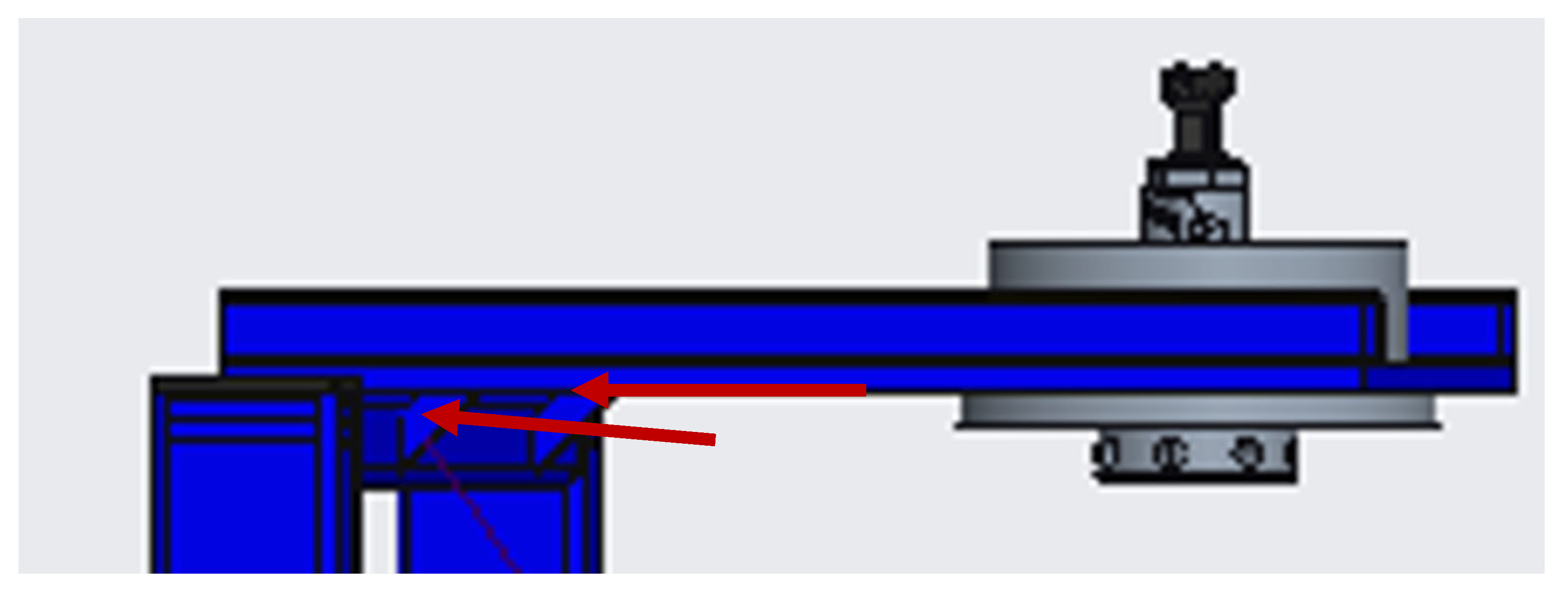
One alternative for achieving a more favorable result would be to double the thickness of the sheet metal. However, a simpler solution was to add two pieces of triangular sheet metal (Figure 4) with a beveled right angle at the point of concentration which exceeds the permissible stress. The figure effectively documents the implementation measure to eliminate exceeding the permissible stresses in critical areas. The arrows show where the tension arises.
2.
Section 2:
  • Calculation of permissible stress σD2:
σ D ( 2 ÷ 5 ) = R e k e = 235 2.5 = 94   MPa
where
𝑅e = 235 [MPa] (yield strength) S235 JRH [11],
ke = 2.5 [–] level of security [1].
  • Calculation of minimum section modulus Wo2min:
W o 2 m i n = M 2 σ D ( 2 ÷ 5 ) = 482 94 = 5.13   cm 3
where
𝑀2 = −482 [Nm] bending moment in Section 2.
In Section l2, it was necessary to maintain a semi-finished product width of 80 mm due to the mounting plate of the screw jack, so a TR OBD 80 × 40 × 3 hollow structural section (HSS) was selected in accordance with the standard and material selection STN EN 10219-1—S235JRH, which has:
A2 = 600 mm2 = 6.0·10−4 m2 [m2] cross-sectional area [33],
Wo2 = 1.3·104 cm3 = 1.3·10−5 m3 [m3] flexural section modulus [33].
  • Shear stress τ2: does not apply, equals 0.
  • Normal stress σ2:
σ 2 = N 2 A 2 + M 2 W o 2 = 1357.75 6.0 · 10 4 + 482   1.3 · 10 5 = 39134120.05   Pa = 39.13   MPa
where
𝑁2 = −1357.75 [N] normal force in Section 2,
𝑀2 = −482 [Nm] bending moment in Section 2.
σ 2 σ D 2 ÷ 5
39.13 MPa ≤ 94 MPa ⟹ profile complies.
3.
Section 3:
  • Calculation of the minimum cross-sectional modulus Wo3min:
W o 3 m i n = M 3 σ D ( 2 ÷ 5 ) = 166.48 94 = 1.77   cm 3
where
𝑀3 = 166.48 [Nm] bending moment in Section 3.
In this section, it was necessary to maintain a semi-finished product width of 110 mm due to the installation of rear wheels, so TR OBD 120 × 40 × 3−995 was selected in accordance with the standard and material selection STN EN 10219-1—S235JRH, which has:
S3 = 1.46·104 mm3 = 1.46·10−5 [m3] static moment [33],
J3 = 2.58·105 mm4 = 0.0258·10−5 [m4] area moment of inertia [33],
Wo3 = 1.29·104 mm3 = 1.29·10−5 [m] flexural section modulus in bending [33].
  • Shear stress τ3:
τ 3 = T 3 · S 3 b 3 · J 3 = 616.62 ·   1.46 · 10 5   0.006 ·   0.0258 · 10 5 = 5815666.667   Pa = 5.82   MPa
where
𝑇3 = 616.62 [N] transverse force in Section 3,
𝑏3 = 6 mm = 0.006 [m] width of the joint (gap)
  • Normal stress σ3:
σ 3 0 = M 3 ( 0 ) W o 3 = 0 1.29   ·   10 5 = 0   MPa
where
𝑀3(0) = 0 [Nm] bending moment in Section 3 location 0.
σ 3 l 3 = M 3 ( 0 ) W o 3 = 166.49 1.29   ·   10 5 = 12906201.55   Pa = 12.9   MPa
where
𝑀3(l3) = 166.49 [Nm] bending moment in Section 3 location l3.
  • Hypothesis of strain energy for shape change σ1red:
σ l 3 r e d   m a x = σ 3   m a x ( l 3 ) 2 + 3 τ 3 2 = 5.82 2 + 3   · 12.9 2 = 23.09   MPa
σ l 3 r e d   m a x σ D 2 ÷ 5
23.09 MPa ≤ 94 MPa ⟹ profile complies.
4.
Section 4:
  • Calculation of the minimum section modulus Wo4min:
W o 4 m i n = M 4 σ D ( 2 ÷ 5 ) = 648.49 94 = 6.89   cm 3
where
𝑀4 = −648.49 [Nm] bending moment in Section 4.
In this section, it was necessary to maintain a semi-finished product width of 90 mm due to the installation of a screw jack, so a TR OBD 90 × 50 × 3 hollow structural section (HSS) was selected in accordance with the standard and material selection STN EN 10219-1—S235JRH, which has:
Wo4 = 1.82·104 mm3 =1.82·10−5 [m3] flexural section modulus in bending [33],
A4 = 780 mm2 = 7.8·10−4 [mm2] cross-sectional area [33].
  • Shear stress τ4: does not apply, equals 0.
  • Normal stress σ4:
σ 4 = N 4 A 4 + M 4 W o 4 = 741.13 7.8 · 10 4 + 648.49 1.82 · 10 5 = 36581485.35   Pa = 36.59   MPa
where
𝑁4 = −741.13 [N] load force in the section,
𝑀4 = −648.49 [Nm] bending moment in Section 4.
σ 4 σ D 2 ÷ 5
36.59 MPa ≤ 94 MPa ⟹ profile complies.
5.
Section 5:
  • Calculation of minimum section modulus Wo5min:
W o 5 m i n = M 5 σ D ( 2 ÷ 5 ) = 648.49 94 = 6.89   cm 3
where
𝑀5 = −648.49 [Nm] bending moment in Section 5.
In this section, it was necessary to maintain a semi-finished product width of 90 mm due to the installation of the front wheels, so TR OBD 120 × 40 × 3 was selected in accordance with the standard and material type STN EN 10219-1—S235JRH, which has:
S5 = 1.46·104 mm3 = 1.46·10−5 [m3] static moment [33],
J5 = 2.58·105 mm4 =0.026·10−5 [m4] area moment of inertia [33],
Wo5 = 1.29·104 mm3 = 1.29·10−5 [mm3] flexural section modulus [33].
  • Shear stress τ5:
τ 5 = T 5 · S 5 b 5 · J 5 = 741.13   ·     1.46 · 10 5   0.006   ·     0.026 · 10 5 = 6989985.788     Pa = 7   MPa
where
𝑇5 = −741.13 [N] transverse force in Section 5,
𝑏5 = 6 mm = 0.006 [m] cross-sectional width.
  • Normal stress σ5:
σ 5 0 = M 5 ( 0 ) W o 5 = 0 1.29   ·   10 5 = 0   MPa
where
𝑀5(0) = 0 [Nm] bending moment in Section 5 location 0.
σ 5 l 5 = M 5 W o 5 = 648.49 1.29 · 10 5 = 50270542.64     Pa = 50.27   MPa
where
𝑀5 = −648.49 [Nm] bending moment in Section 5.
  • Hypothesis of strain energy for shape change σ5red:
σ l 5 r e d   m a x = σ 5   m a x ( l 5 ) 2 + 3 τ 5 2 = 50.27 2 + 3   · 7 2 = 51.71   MPa
σ l 5 r e d   m a x σ D 2 ÷ 5
51.71 MPa ≤ 94 MPa ⟹ the profile is suitable.
Based on the calculated bending moments and shear forces, the required section modulus Wo was determined, and the corresponding normal and shear stresses were calculated in critical regions. These results were compared with the allowable stress derived from the material properties of steel, considering a safety factor of ke = 2.5. Where stress exceeded permissible limits, reinforcement solutions (e.g., additional stiffeners) were applied. This step verified that the optimized structure meets both strength and stability requirements.

3. Results and Discussion

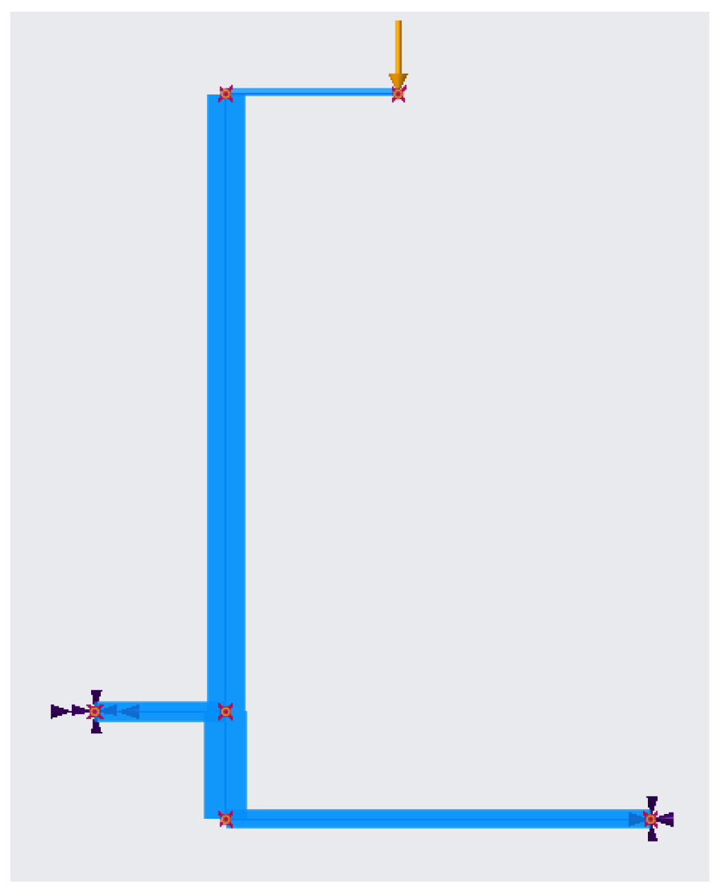
First, it was necessary to model the parts of the trolley structure, followed by an analysis using Creo Simulate. The created structure, including the load force and connections, is shown in Figure 5. The model presents the structure, including the applied load and connections.

3.1. Comparison of Internal Force Effects Results with Creo Simulate

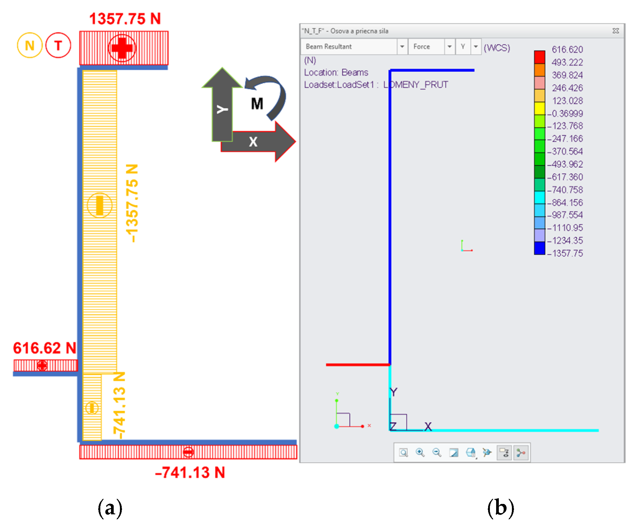
Figure 6 shows a comparison of the axial and transverse force graphs. These graphs represent the direct output from the analytical calculation and Creo Simulate. On the left are the calculated mathematical relationships, and on the right is the output from the analysis created in Creo Simulate. They match with one exception, namely the sign of the transverse force acting in Section 1 (Figure 3b). Since this is shear, it does not matter whether the force acts upwards or downwards at the point of the imaginary cut. This inequality may result in different coordinate systems.
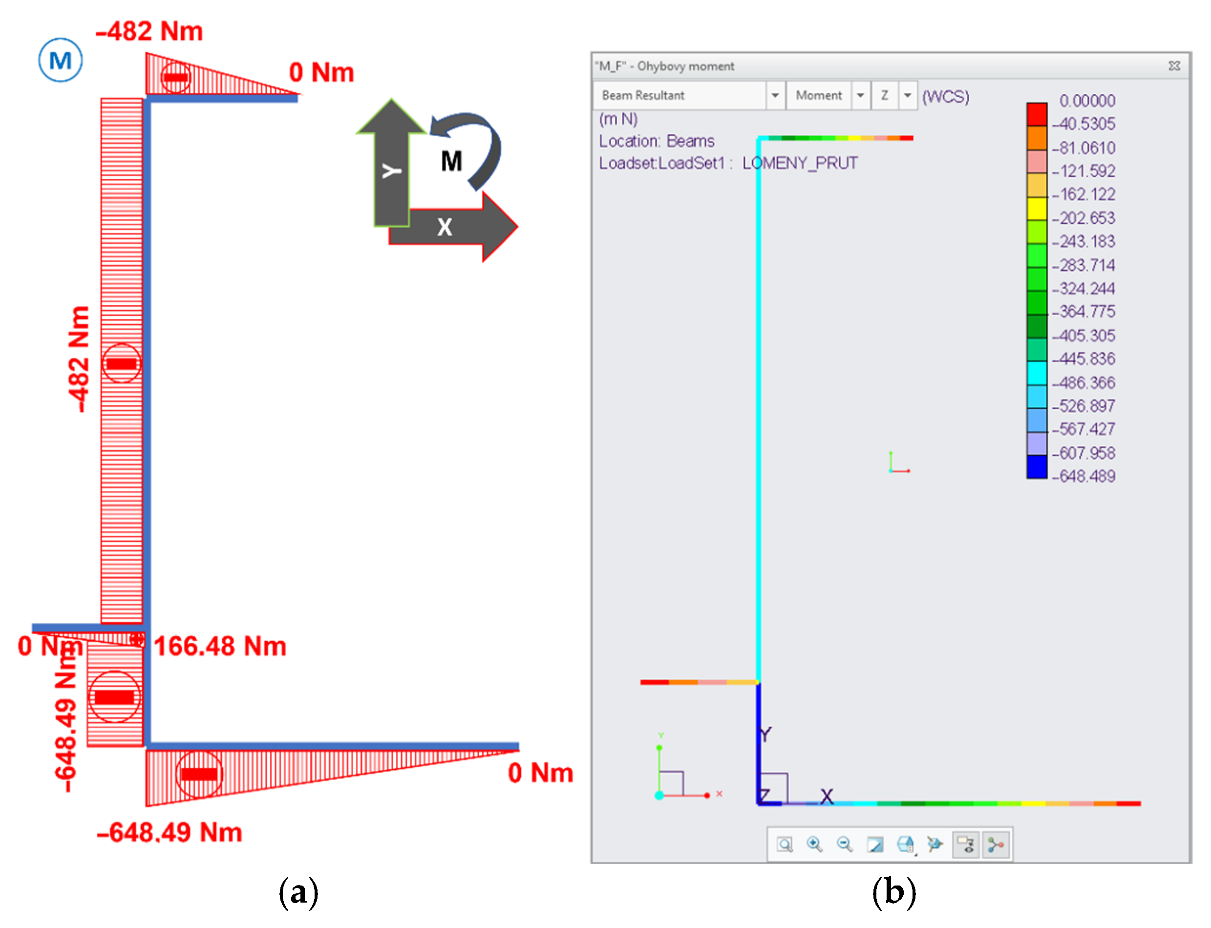
When comparing the bending moment, the graphs match (see Figure 7).

3.2. Comparison of Stress Results with Creo Simulate

In the model created in Figure 4, we displayed the results of reduced stress according to the “von Mises stress” hypothesis from the analysis. A comparison of the results of the calculated force effects according to mathematical relationships and the results of the analysis using the Creo Simulate program is shown in Table 2. Individual deviations in stress are caused by the simplification of the 2D model.
We then compared the calculated values with the results of the Creo Simulate analysis graphically, as shown in Figure 8. This visualization allows for quick identification of critical stress areas.
The reason for the different stress values in Section 1 (Table 2) lies in the methodology used. The analytical calculation was based on a simplified two-dimensional (2D) model, which cannot fully capture the spatial distribution of forces and the stiffness of the entire structure. In contrast, Creo Simulate analyzed a complex 3D spatial model, which provided a much more accurate and realistic picture of the actual stress state. The simplified 2D model led to incorrect stress concentration and its significant overestimation.
The presented research focuses on the design and structural verification of a specialized handling trolley intended for transporting clamping fixtures in production conditions. The analytical approach, based on the theory of broken rods, provided a simplified but sufficiently accurate framework for the initial dimensioning of the load-bearing parts of the structure. Subsequent finite element analysis (FEA) in the Creo Simulate environment verified the theoretical assumptions and identified areas with increased stress concentration, which were then eliminated by specifically designed reinforcing elements.
Compared to existing solutions [8,27], the proposed solution strikes a pragmatic balance between structural strength and ergonomic comfort. While previous studies have emphasized the need for automated or motor-driven handling systems to reduce musculoskeletal risks, our design demonstrates that appropriate structural optimizations (e.g., wheel configuration, placement of reinforcing elements) can achieve a comparable reduction in physical strain on the operator while maintaining cost-effectiveness and structural simplicity.
During the simulation phase, slight deviations were observed between the analytically calculated stress values and the FEA results. These differences, generally not exceeding 6–8%, are attributed to simplifications in the 2D analytical model, which cannot fully capture the complex geometric relationships in the area of welded joints. Nevertheless, the degree of agreement was considered sufficient given the operating conditions of the prototype.
Verification of the prototype in a real production environment confirmed the ergonomic benefits of the proposed solution, as a single operator was able to safely handle fixtures weighing up to 300 kg with minimal physical effort. These results correspond with the findings [24], which point to the importance of reducing handling forces through the precise design of manual transport devices. Results of a pilot study of a trolley-lifter study for back pain show a conglomeration of working time and subsequent working time [30].
When removing the fixture, the clamping fixture must be open. Then, using a screw jack, lift the movable part of the trolley with the clamping fixture above the level of the stand with the removal fixture and slide the trolley in to remove it. Lower the movable part so that it comes into contact with the removal device and secure the clamping device using the lever on the upper side. The entire operation is illustrated in Figure 9.
To reduce resistance when pulling out the removal device, use a screw jack to lift the movable part with the clamped removal device and pull the trolley out of the stand. To insert the removal device clamped on the handling trolley, proceed in the opposite manner to that described in the previous paragraph.
This prototype improves efficiency compared to conventional handling methods, ideally with some quantifiable benefits (e.g., reduced handling time, fewer operators required).
The prototype was experimentally verified by deploying it under full load in the working environment for which it was designed. Almost a year has passed since its full deployment, and the prototype is working without any problems. One operator is sufficient to handle the truck and load safely and easily. We did not perform any other verification, as the most relevant proof of full functionality, load handling, and safe use is the fact that since the trolley was deployed work has been accelerated and simplified, and the trolley can handle the loads for which it was designed without any problems.
Compared with conventional manual handling methods, the prototype trolley reduced handling time by approximately 25% and allowed tasks that previously required two operators to be completed by one operator. This not only improves productivity but also significantly reduces the physical strain placed on workers.

3.3. Patent Protection and Practical Implementation

The successful validation of the prototype in an industrial environment led to the granting of patent protection.
The innovative design resulted in a utility model that addresses the construction of a handling trolley.
  • Vargovská, M.; Čierťažský, R.; Minárik, M. Handling trolley for sand core clamping fixture. Slovak Republic utility model SK 10144 Y1, 25 September 2024 (in Slovak).
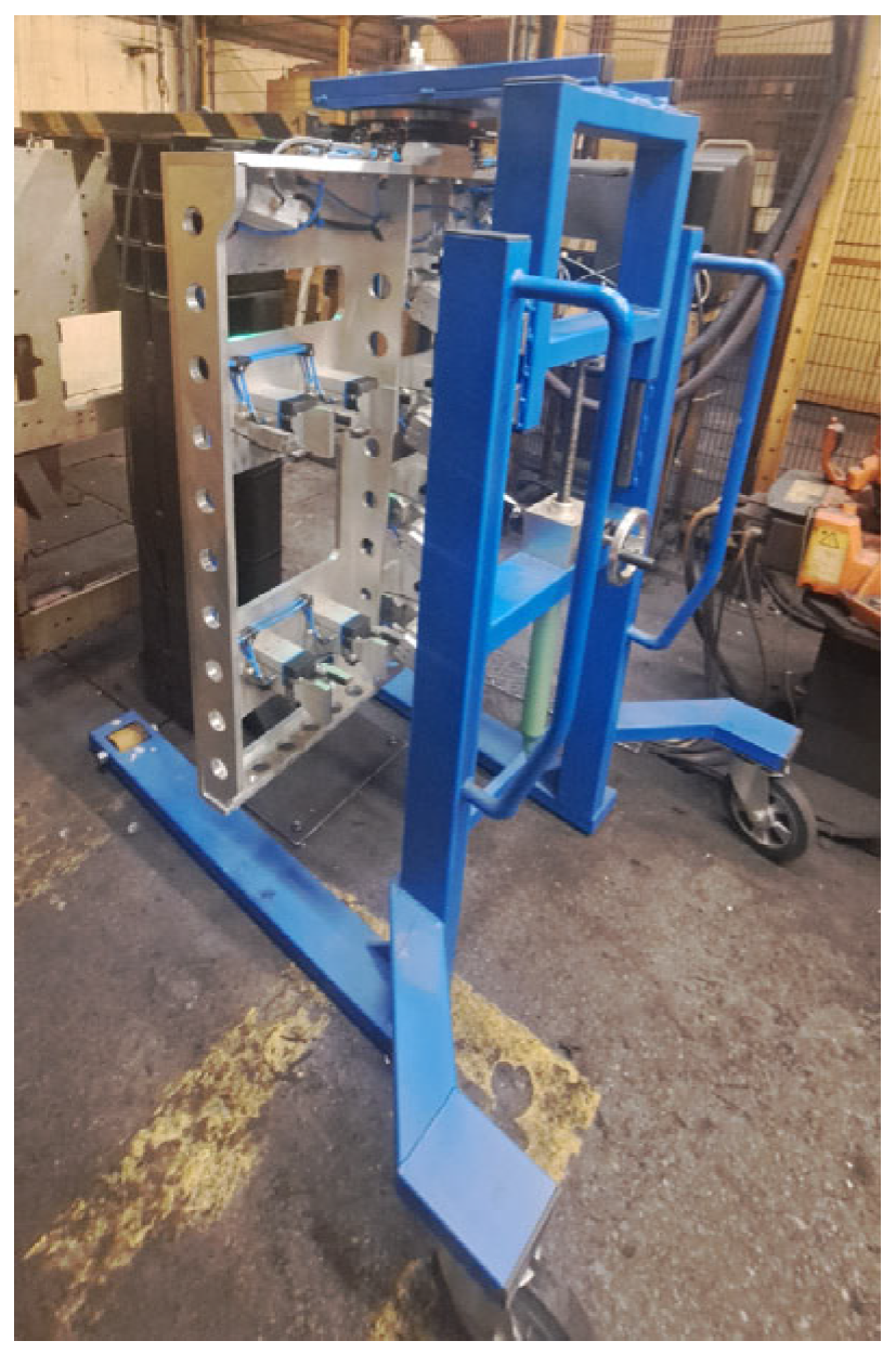
The technical solution relates to a handling trolley used to transport sand core clamping fixture, but it can also be used for other types of tools. The trolley design consists of a fixed lower part and a movable upper part. The innovation lies in the arrangement, which allows for the safe and stable transport of heavy sand cores by one person. Figure 10 shows the prototype that has already been manufactured and is used to handle the material in question. Figure 10 documents the final prototype, which has already been implemented in practice. The importance and benefit of prototype solutions in various fields is inherent. The authors of the article also provide membrane technologies for removing emerging contaminants from wastewater in this way, as they are sometimes subject to industry preconditions that may be required to obtain information on related patent licenses or to establish startups [34].

4. Conclusions

This paper presents the design and verification of a prototype solution for a handling trolley intended for the handling and transport of clamping fixture in production conditions. By combining analytical calculations based on the theory of broken rods and simulation analysis in the Creo Simulate environment, it was possible to design a structure that meets the requirements for load capacity, stability, and safety.
A comparison of the results from the computational model and the simulation showed very good agreement, with differences in stress values in some sections caused by simplifying assumptions in the 2D model. Critical areas with stress concentration were identified and subsequently reinforced through design modifications, thereby eliminating the exceeding of permissible stresses.
The proposed solution also proved to be suitable from an ergonomic point of view, as it allows safe and efficient handling of heavy fixtures by one person. The prototype was successfully tested in real production conditions, where it proved its practical usability.
In the future, further development of the solution is expected towards its modularization for different types of fixtures and more complex validation in long-term operating conditions.
Future research will focus on extending the modular adaptability of the trolley for different product sizes and exploring the possibilities of integrating sensor systems for real-time load monitoring.
Future research will focus on long-term durability testing under continuous operation, scaling the prototype for different fixture types, and exploring potential commercialization pathways in cooperation with industrial partners.

Author Contributions

Conceptualization, methodology, software, and writing—original draft preparation, M.V.; validation and writing—review and editing, R.Č.; supervision, project administration, and funding acquisition, E.P. All authors have read and agreed to the published version of the manuscript.

Funding

This research was funded by the KEGA 002TU Z-4/2023 project “Innovation of the educational process through the application of new didactic approaches focusing on mechanisms in transport and handling as tools for improving the quality of professional knowledge and critical thinking” and the KEGA 004TU Z-4/2024 “Implementation of progressive methods of education in professional subjects in the field of mechanical engineering and industrial robotics”.

Data Availability Statement

Not applicable.

Conflicts of Interest

The authors declare no conflicts of interest.

References

  1. Blatnicky, M.; Dizo, J.; Gerlici, J.; Saga, M.; Lack, T.; Kuba, E. Design of a robotic manipulator for handling products of automotive industry. Int. J. Adv. Robot. Syst. 2020, 17, 1729881420906290. [Google Scholar] [CrossRef]
  2. Zajacko, I.; Gál, T.; Ságová, Z.; Mateichyk, V.; Wiecek, D. Application of artificial intelligence principles in mechanical engineering. In Proceedings of the 3rd International Scientific Conference on Innovative Technologies in Engineering Production (ITEP), Bangkok, Thailand, 12–14 December 2018; Volume 244. [Google Scholar] [CrossRef]
  3. Kuric, I.; Klarak, J.; Bulej, V.; Saga, M.; Kandera, M.; Hajducik, A.; Tucki, K. Approach to Automated Visual Inspection of Objects Based on Artificial Intelligence. Appl. Sci. 2022, 12, 864. [Google Scholar] [CrossRef]
  4. Vargovská, M.; Minárik, M. Innovative Solutions for Handling Mechanisms at Handling Wood Material, 1st ed.; Technical University in Zvolen: Zvolen, Slovakia, 2024. (In Slovak) [Google Scholar]
  5. Banský, M.; Michna, S.; Plagany, J.; Radi, J. Universal CNC Grinding Machine; Technical University in Zvolen: Zvolen, Slovakia, 2007. (In Slovak) [Google Scholar]
  6. Siddharta, R. Introduction to Materials Handling; National Institute of Technical: Kolkata, India, 2015. [Google Scholar]
  7. Leggieri, S.; Falco, V.; D’Andrea, C.N. Online Ergonomic Evaluation in Realistic Manual Material Handling Task. Bioengineering 2023, 11, 14. [Google Scholar] [CrossRef] [PubMed]
  8. Umar, R.Z.R.; Ahmad, N.; Halim, I.; Lee, P.Y.; Hamid, M. Design and Development of an Ergonomic Trolley-Lifter for Sheet Metal Handling Task. Saf. Health Work 2019, 10, 327–335. [Google Scholar] [CrossRef] [PubMed]
  9. STN EN 10219-1:2007; Cold Formed Hollow Sections of Non-Alloy and Fine-Grained Structural Steels. Part 1: Technical Delivery Conditions. Slovak Institute of Technical Standardization: Bratislava, Slovakia. (In Slovak)
  10. STN EN 10305-3:2010; Precision Steel Tubes. Part 3: Cold Drawn Welded Tubes. Slovak Institute of Technical Standardization: Bratislava, Slovakia. (In Slovak)
  11. STN EN 10025-2:2019; Hot-Rolled Products of Structural Steels. Part 2: Technical Delivery Conditions for Non-Alloy Structural Steels. Slovak Institute of Technical Standardization: Bratislava, Slovakia. (In Slovak)
  12. Structural Steels. Available online: http://old.konstrukce.cz/clanek/volba-konstrukcnich-oceli-pro-stavebni-svarovane-konstrukce-podle-vyznamu-oznaceni/ (accessed on 26 February 2023).
  13. Bodnár, F. Elasticity and Strength I; Technical University in Zvolen: Zvolen, Slovakia, 2008. (In Slovak) [Google Scholar]
  14. Vita, L.; Gattamelata, D. Analytical Method for Assessing Stability of a Counterbalanced Forklift Truck Assembled with Interchangeable Equipment. Appl. Sci. 2023, 13, 1206. [Google Scholar] [CrossRef]
  15. Oh, H.J.H.; Liew, K.W.; Ng, P.K.; Lim, B.K.; Tay, C.H.; Khoh, C.L. An Innovative Solution for Stair Climbing: A Conceptual Design and Analysis of a Tri-Wheeled Trolley with Motorized, Adjustable, and Foldable Features. Inventions 2025, 10, 57. [Google Scholar] [CrossRef]
  16. Van der Woude, L.H.V.; Geurts, C.; Winkelman, H.; Veeger, H.E.J. Measurement of wheelchair rolling resistance with a handle bar push technique. J. Med. Eng. Technol. 2003, 27, 249–258. [Google Scholar] [CrossRef] [PubMed]
  17. Sauret, C.; Bascou, J.; de Saint Rémy, N.; Pillet, H.; Vaslin, P.; Lavaste, F. Assessment of field rolling resistance of manual wheelchairs. J. Rehabil. Res. Dev. 2012, 49, 63–74.S. [Google Scholar] [CrossRef] [PubMed]
  18. Sandfeld, J.; Rosgaard, C.; Jensen, B.R. L4-L5 compression and anterior/posterior joint shear forces in cabin attendants during the initial push/pull actions of airplane meal carts. Ergonomics 2014, 45, 1067–1075. [Google Scholar] [CrossRef] [PubMed]
  19. Leban, B.; Fabbri, D.; Lecca, L.I.; Uras, M.; Monticone, M.; Porta, M.; Pau, M.; Campagna, M. Characterization of hand forces exerted during non-powered hospital bed pushing and pulling tasks. Int. J. Occup. Saf. Ergon. 2022, 28, 991–999. [Google Scholar] [CrossRef] [PubMed]
  20. Sprigle, S.; Huang, M.; Misch, J. Measurement of rolling resistance and scrub torque of manual wheelchair drive wheels and casters. Assist. Technol. 2019, 34, 91–103. [Google Scholar] [CrossRef] [PubMed]
  21. Silva, L.C.A.; Dedini, F.G.; Corrêa, F.C.; Eckert, J.J.; Becker, M. Measurement of wheelchair contact force with a low cost bench test. Med. Eng. Phys. 2016, 38, 163–170. [Google Scholar] [CrossRef] [PubMed]
  22. Al-Eisawi, K.W.; Kerk, C.J.; Congleton, J.J.; Amendola, A.A.; Jenkins, O.C.; Gaines, W. Factors affecting minimum push and pull forces of manual carts. Appl. Ergon. 1999, 30, 235–245.S. [Google Scholar] [CrossRef] [PubMed]
  23. Banský, M.; Svoreň, J.; Plagany, J. Obrábacie Centrum pre Porez Drevnej Suroviny; Technická Univerzita vo Zvolene: Zvolen, Slovakia, 2006. [Google Scholar]
  24. Zhang, Y.; Lin, K.Y.; Lin, J.H. Factors Affecting Material-Cart Handling in the Roofing Industry. Int. J. Environ. Res. Public Health 2021, 18, 1510. [Google Scholar] [CrossRef]
  25. Amio, F.F.; Ahmed, N.; Jeong, S.; Jung, I.; Nam, K. Optimizing Precision Material Handling: Elevating Performance and Safety through Enhanced Motion Control in Industrial Forklifts. Electronics 2024, 13, 1732. [Google Scholar] [CrossRef]
  26. Anggono, W.; Rakhmawati, R.; Saputra, A. Redesign Materials Handling System by Using Ergonomic Approaches to Reduce Back Pain Risk. In Advances in Intelligent Systems and Computing; Springer: Singapore, 2018; Volume 605, pp. 469–475. [Google Scholar] [CrossRef]
  27. Gille, S. Design of Manual Handling Carts: A Novel Approach Combining Corrective Forces and Modelling to Prevent Injuries. Safety 2025, 11, 25. [Google Scholar] [CrossRef]
  28. Ahmad, I.; Abidin, A.A.Z.; Mohd Yusoff, H.H.; Sapuan, S.M.; Ahmad, R.; Jamil, M.A. Sheet Metal Manual Handling Aids: Effects of Design Differences on Muscle Activity and Subjective Assessment. IIUM Eng. J. 2023, 24, 45–55. Available online: https://journals.iium.edu.my/ejournal/index.php/iiumej/article/view/3397 (accessed on 8 August 2025). [CrossRef]
  29. Gumasing, M.J. An Ergonomic Design of Six-Wheeled Trolley for Transportation of a 100-kg Weight Load. In Proceedings of the International Conference on Industrial Engineering and Operations Management, Dubai, United Arab Emirates, 10–12 March 2020; Available online: https://index.ieomsociety.org/index.cfm/article/view/ID/4301 (accessed on 8 August 2025).
  30. Siska, R.; Syahbana, A. Design of an Ergonomic Trolley for Plate Handling Task Using OWAS and Ergonomic Function Deployment. Spektrum Ind. 2020, 18, 47–58. [Google Scholar] [CrossRef]
  31. Singh, T.; Kumar, R.; Sharma, S. Development of a Trolley-Lifter for Sheet Metal Handling: Ergonomic Evaluation and Pilot Testing. Int. J. Occup. Saf. Ergon. 2019, 25, 523–531. [Google Scholar]
  32. Industrial Property Office of the Slovak Republic. Úžitkový vzor č. 25-2024. Available online: https://wbr.indprop.gov.sk/WebRegistre/UzitkovyVzor/Detail/25-2024 (accessed on 31 July 2025).
  33. ClearCalcs. Free Moment of Inertia Calculator. Available online: https://clearcalcs.com/freetools/free-moment-of-inertia-calculator/au (accessed on 26 February 2023).
  34. Han, B.; Gabriel, J.-C.P. Thin-film nanocomposite (TFN) membrane technologies for the removal of emerging contaminants from wastewater. J. Clean. Prod. 2024, 480, 144043. [Google Scholar] [CrossRef]
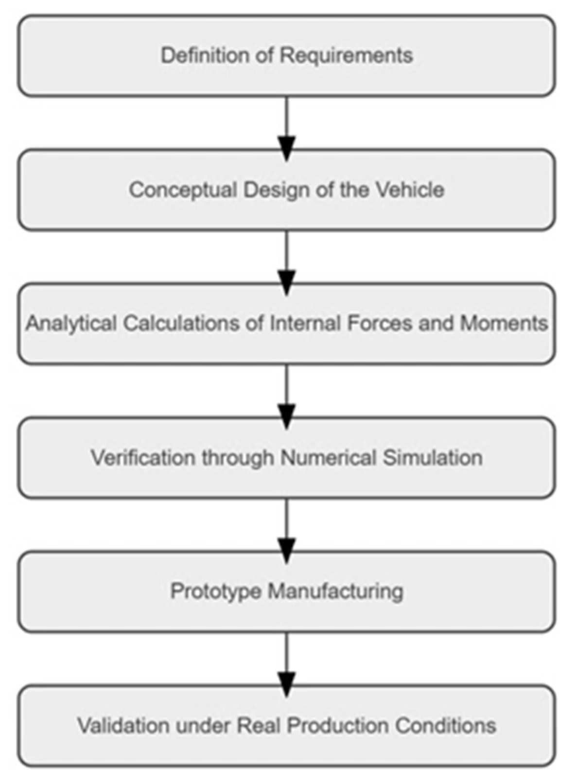
Figure 1. Technical workflow diagram.
Machines 13 00775 g001
Figure 2. Handling trolley. 1—fixed part, 2—upper movable part, 3—consists of forks, 4—wheels for pallet trucks, 5—U-shaped frame, 6—swivel wheels, 7—vertical columns, 8—linear guide rails, 9—steel hollow section, 10—the screw jack, 11—mounting plate [19].
Machines 13 00775 g002
Figure 3. Basic structural frame. (a) Dimensions of the rods of the structure created in Creo Parametric; (b) bent rod.
Machines 13 00775 g003
Figure 4. Reinforcing plates.
Machines 13 00775 g004
Figure 5. Model design in Creo Simulate.
Machines 13 00775 g005
Figure 6. Comparison of N and T curves. (a) Graph constructed from calculated mathematical relationships; (b) output from Creo Simulate.
Machines 13 00775 g006
Figure 7. Comparison of M. (a) Graph constructed from calculated mathematical relationships; (b) output from Creo Simulate.
Machines 13 00775 g007
Figure 8. Normal stress result from Creo Simulate.
Machines 13 00775 g008
Figure 9. Trolley in the clamping/unclamping position.
Machines 13 00775 g009
Figure 10. Manufactured handling trolley.
Machines 13 00775 g010
Table 1. Acting force and dimensions of the structure.
Force/SectionValueConversion of Units
𝐹 = 𝐹Cup/23075.5/2 N1357.75 N
l1355 mm0.355 m
l21272 mm1.272 m
l3270 mm0.270 m
l4221.5 mm0.2215 m
l5875 mm0.875 m
Table 2. Comparison of normal stress results.
VariableCalculated Result (MPa)Result of Creo Simulate Analysis (MPa)
σ(1(0))
σ(1(l1))
0 → (Equation (37))1.620 × 10⁻³ ≐ 0
411.15 → (Equation (38))1.265 × 10 = 12.65
σ239.13 → (Equation (42))3.650 × 10 = 36.5
σ(3(0))
σ(3(l3))
0 → (Equation (45))7.896 × 10⁻³ ≐ 0
12.9 → (Equation (46))1.248 × 10 = 12.48
σ436.59 → (Equation (49))3.469 × 10 = 34.69
σ(5(0))0 → (Equation (52))3.160 × 10⁻¹³ ≐ 0
σ(5(l5))50.27 → (Equation (53))4.862 × 10 = 48.62
Disclaimer/Publisher’s Note: The statements, opinions and data contained in all publications are solely those of the individual author(s) and contributor(s) and not of MDPI and/or the editor(s). MDPI and/or the editor(s) disclaim responsibility for any injury to people or property resulting from any ideas, methods, instructions or products referred to in the content.