1. Introduction
In recent years, the explosive expansion of high-performance motor drive applications has triggered growing interest in advanced alternating current (AC) motor control technologies across academia, industry, and governmental entities. Among various AC motor types, PMSM have established themselves as a pivotal element in servo control systems, attributed to their high energy efficiency, exceptional power density, and compact configuration [
1,
2,
3].
Conventional control methodologies for PMSM encompass field-oriented control (FOC), direct torque control (DTC), and model predictive control (MPC). Nevertheless, PMSM control systems are characterized by pronounced nonlinearity and parameter sensitivity—limitations that render traditional proportional-integral (PI)-based FOC inadequate in terms of dynamic responsiveness and disturbance rejection capabilities [
4,
5]. While DTC boasts a straightforward structural design, its hysteresis-based control architecture gives rise to substantial current ripple and fluctuations in switching frequency [
6]. MPC, by contrast, leverages a discretized system model to predict the future states of the motor through online rolling optimization. It identifies the optimal voltage vector by assessing a predefined cost function. Compared with the heuristic switching tables employed in conventional DTC, MPC generates voltage vectors directly via optimization algorithms, thereby achieving effective suppression of current ripple and a notable improvement in control accuracy. Relative to the cascaded regulatory framework of PI-FOC, MPC’s multivariable cooperative optimization mechanism further elevates the dynamic response rate [
7].
MPC for PMSM can be categorized into model predictive torque control (MPTC) and model predictive current control (MPCC), with the classification dictated by their respective control objectives. MPTC confronts heightened complexity in parameter tuning, primarily stemming from the necessity to coordinate torque–flux weighting factors—an issue that introduces trade-offs between torque response and flux regulation. In contrast, MPCC streamlines control implementation by centering exclusively on current reference tracking, thereby circumventing the need for such weighting coordination [
8]. Nonetheless, conventional MPCC is plagued by two critical limitations: first, excessive computational overhead induced by the exhaustive enumeration of all candidate voltage vectors within the control set; second, constrained capability in suppressing steady-state current harmonics [
9,
10]. From a different classification perspective, MPC schemes can also be distinguished based on the characteristics of their control sets. Continuous control set MPC (CCS-MPC) achieves smooth system operation through pulse-width modulation (PWM)-based continuous voltage modulation [
11,
12,
13], whereas finite control set MPC (FCS-MPC) implements discrete control by directly utilizing the switching states of the inverter [
14,
15,
16]. While FCS-MPC exhibits superior dynamic response performance compared to CCS-MPC, it gives rise to inherent challenges such as variable switching frequency and torque ripple. Despite these drawbacks, FCS-MPC has witnessed a growing uptake in motor drive applications, attributed to its unique advantages—including efficient handling of multiple system constraints, inherent robustness against parameter variations, and the elimination of independent modulation modules.
Within the domain of FCS-MPC, single-vector control has been widely adopted, owing to its algorithmic simplicity, fast dynamic response, and straightforward cost function configuration. However, this approach is constrained to selecting only one of the eight basic voltage vectors in each control cycle. Due to the fixed magnitude of the chosen vector, the precision of voltage vector matching is impaired, which in turn degrades the overall control performance. These limitations have redirected research attention toward multi-vector control strategies, which enhance system performance through optimized vector synthesis. Reference [
17] proposed a duty-cycle modulated MPCC method that enables continuous regulation of voltage in both magnitude and phase by temporally combining active and null vectors. Nevertheless, the selection of its sub-optimal vector (
uₒₚₜ
2) was confined to null vectors—a restriction that limits control flexibility. To address this constraint, Reference [
18] developed a DV-MPCC strategy, expanding the selection range of
uₒₚₜ
2 to all available voltage vectors. That said, given that each vector has seven possible states (six active vectors and one null vector), the dual-vector approach requires evaluating forty-nine potential vector combinations, leading to a substantial increase in computational burden [
19].
To mitigate this challenge, Reference [
20] designed a fast voltage vector selection algorithm based on d-q axis current deviation criteria. This algorithm reduces the computational complexity by cutting the number of evaluated combinations from 49 to just 3, shortening the execution time from 24.5 μs to 20.5 μs. Although this method effectively reduces the number of prediction iterations, its execution time (20.5 μs) remains slightly longer than that of conventional single-vector MPCC (19.1 μs). Subsequently, Reference [
21] presented a computationally efficient DV-MPCC strategy, which restricts the candidates for the optimal primary vector (
uₒₚₜ
1) to the previously applied active vector and its two adjacent vectors. This approach achieves an average computation time of 15.3 μs while lowering the total harmonic distortion (THD) of the current to 6.57%. However, during dynamic operating conditions, the method reverts to single-vector MPCC, sacrificing the steady-state advantages inherent in dual-vector control. Further advancements were made with Reference [
22]’s current error vector projection method, which minimizes the cost function by projecting error vectors onto the directions of voltage vectors, thereby reducing the number of candidate vectors to be evaluated. This approach, however, exhibits robustness limitations that depend on the spatial relationship between the reference current vector and the naturally decaying current vector. Reference [
23] then introduced a timing calculation method based on current difference parameters. By leveraging the previous zero-vector states and sector information, this method accelerates the optimal vector selection process by 36%. Nevertheless, its effectiveness heavily relies on pre-defined vector tables and accurate detection of sector boundaries. Most recently, Reference [
24] put forward a strategy based on the minimum deviation principle, which reconstructs the vector selection table through deviation optimization analysis. This method achieves a 14.77% reduction in torque ripple without compromising current THD. That said, it requires advanced theoretical analysis for the implementation of new switching tables and precise timing calculations.
While the aforementioned studies have achieved respective advancements in vector synthesis, vector selection, and duration optimization, striking an optimal balance between computational efficiency and control accuracy remains a critical challenge that demands further investigation and resolution.
While the current loop achieves high-precision current tracking via multi-vector modulated MPCC, speed regulation still typically relies on conventional PI control. This hybrid control architecture suffers from inherent limitations, which stem from the fundamental incompatibility between the linear characteristics of PI controllers and the nonlinear dynamic behavior of motor systems. Notably, during load transients or rapid speed variations, this configuration exhibits a marked degradation in dynamic responsiveness and disturbance rejection capabilities [
25]. To overcome these constraints, recent advances have focused on integrating robust SMC with MPCC—a synergy that effectively enhances the overall performance of the control system [
26]. This integrated approach leverages the current regulation superiority of MPCC and the nonlinear control advantages of SMC, making it particularly well-suited for applications that demand both high-precision current tracking and robust speed regulation.
SMC exhibits exceptional robustness and rapid dynamic responsiveness in speed regulation scenarios, rendering it highly effective in addressing parameter variations, load disturbances, and nonlinear effects—all while maintaining relatively low reliance on accurate system modeling. These attributes make SMC particularly well-suited for high-performance motion control applications, such as PMSM speed regulation and robotic joint actuation, where stringent dynamic performance requirements must be met [
27]. Nevertheless, a critical limitation of SMC lies in its inherent chattering phenomenon, which arises from high-frequency switching in the control law. This chattering may trigger mechanical vibrations, excessive acoustic noise, and even accelerated wear of mechanical components—issues that demand effective suppression strategies to ensure the feasibility of SMC in practical engineering deployments.
The reaching law constitutes a foundational element in SMC design, dynamically governing the convergence rate of system state trajectories. Its core functions include ensuring finite-time stabilization of these trajectories on predefined sliding surfaces while effectively attenuating chattering induced by abrupt control actions. Owing to its design versatility and computational efficiency, this methodology has evolved into a prominent research focus in contemporary SMC investigations [
28]. Gao pioneered the conceptualization and application of diverse reaching laws, encompassing the constant rate reaching law (CRRL) [
29,
30], exponential reaching law (ERL) [
31,
32], and power rate reaching law (PRL) [
33,
34]. However, these conventional formulations often exhibit compromised global convergence speeds and demonstrate limited efficacy in disturbance rejection. To address these inadequacies, Zhang et al. [
35] developed a novel sliding mode reaching law (NSMRL) within the traditional ERL framework, specifically tailored to enhance dynamic performance in PMSM speed regulation systems. As research into sliding mode reaching laws advances increasingly, a composite reaching law (which incorporates system state variables and is modulated by the absolute value of switching functions) has been proposed. This innovation features dual operational modes with distinct dynamic characteristics. Parallel developments in [
36] demonstrated accelerated convergence rates through a modified ERL implementation within fractional-order SMC architectures. Beyond these fundamental enhancements, contemporary research has explored synergistic integrations of SMC with computational intelligence techniques. Notably, Reference [
37] developed a novel two-stage hybrid control scheme incorporating improved particle swarm optimization. While this approach successfully retains the inherent fast response characteristics of SMC, it introduces new challenges, including heightened implementation complexity and stringent parameter tuning requirements in practical engineering deployments.
When designing SMC systems via sliding mode reaching law (SMRL)-based approaches, a critical limitation persists in the inherent chattering phenomenon—one that originates from discontinuous control laws and high-frequency switching operations in the vicinity of sliding surfaces [
38]. Given that the control law is directly derived from the adopted reaching law, the design of SMRL plays a pivotal role in both chattering suppression and reaching time minimization. Reference [
39] proposed a modified SMRL that incorporates system state variables and power terms, which exhibits enhanced transient responsiveness and disturbance rejection capabilities. However, this method still relies on discontinuous sign functions, an inherent feature that inevitably induces chattering. To further alleviate this issue, Sun et al. [
40] improved the conventional exponential reaching law by introducing a terminal switching gain term and replacing the sign function with a saturation function. This modification yields superior robustness against system uncertainties. As an alternative approach, Xu et al. [
41] developed an enhanced SMRL for non-singular fast terminal sliding mode control (NFTSMC), where sign functions are substituted with hyperbolic tangent functions. This substitution effectively reduces chattering while improving tracking precision. Nevertheless, these advanced reaching laws achieve chattering suppression at the cost of prolonged convergence time, failing to concurrently optimize both fast transient response and chattering mitigation—two core performance metrics in SMC design.
In recent years, high-order sliding mode control (HOSMC) strategies have demonstrated excellent theoretical performance. For instance, Ullah et al. proposed a variable-gain fractional-order super-twisting sliding mode control method in [
42]. By integrating fractional calculus with an adaptive gain adjustment mechanism, this method achieves the dual optimization of finite-time convergence and chattering suppression, providing a crucial reference for enhancing the robustness of PMSM control systems. Such methods exhibit outstanding anti-disturbance capability and dynamic response speed under complex operating conditions, significantly advancing the development of sliding mode control theory.
In [
43], a fast super-twisting algorithm (FSTA) with an enhanced exponential term was innovatively introduced. By dynamically adjusting the switching gain, this algorithm not only retains the fast convergence characteristic of traditional SMC but also significantly suppresses the inherent chattering phenomenon in SMC. Meanwhile, the study combines model reference adaptive theory (MRAT) to design an adaptive feedback gain, which further improves the error convergence speed of the system under variable operating conditions and effectively optimizes both the dynamic response performance and steady-state control accuracy of the sliding mode controller.
Addressing the singularity issue existing in traditional terminal sliding mode control (TSMC), a NFTSMC method was proposed in [
44]. Through the design of a sliding surface with high-order error terms, this method ensures the finite-time convergence characteristic of the system while successfully avoiding the singularity risk in traditional TSMC. Furthermore, the novel reaching law (NRL) constructed in this study can dynamically adjust the reaching speed according to the real-time state of the system, effectively balancing the contradiction between chattering suppression effect and convergence efficiency. Additionally, the matched disturbance observer can provide accurate disturbance compensation for the sliding mode controller, further enhancing the anti-disturbance performance of the system.
However, there are still directions in existing sliding mode control-related studies that require further optimization. The complex nonlinear operations involved in FSTA and NFTSMC impose high demands on hardware computing capabilities. Considering the limitations of the main frequency and computing power of DSP commonly used in practical engineering (such as the TMS320C28346 adopted in this paper), their complex nonlinear operations may lead to an extension of the control cycle. Therefore, it is necessary to explore improved paths that are more conducive to engineering implementation.
Building on the aforementioned analysis, this paper proposes a novel DV-MPCC strategy for PMSM drive systems, integrated with an IEAL-SMC. The principal contributions of this work are threefold:
(1) A voltage phase angle-based dual-vector model predictive current control (VPA-DV-MPCC) algorithm is proposed. This innovative method directly identifies the optimal voltage vector sector using the q-axis current reference (iq*) output by the speed loop while simultaneously expanding the range of candidate voltage vectors. Notably, this approach reduces the number of current predictions required per control cycle from 97 to merely 7 iterations—a significant reduction that enhances computational efficiency without sacrificing control accuracy. Furthermore, the algorithm achieves dynamic coupling between the speed control loop and current control loop, fostering coordinated operation of the two loops.
(2) For the speed loop design, a softsign switching function is incorporated to construct an exponential reaching law, leading to the development of an improved IEAL-SMC. The softsign function, equipped with a smooth parameter factor, enables dynamic adaptive adjustment: it preserves fast convergence characteristics when the system state is far from the sliding surface while automatically transitioning to a chattering suppression mode as it approaches the sliding surface. Furthermore, through rigorous proof utilizing Lyapunov stability theory, the global asymptotic stability of the closed-loop control system is formally guaranteed. Additionally, the softsign function only involves simple arithmetic operations, resulting in low computational complexity, which can meet the real-time requirements of high-speed dynamic response of the motor while ensuring control performance.
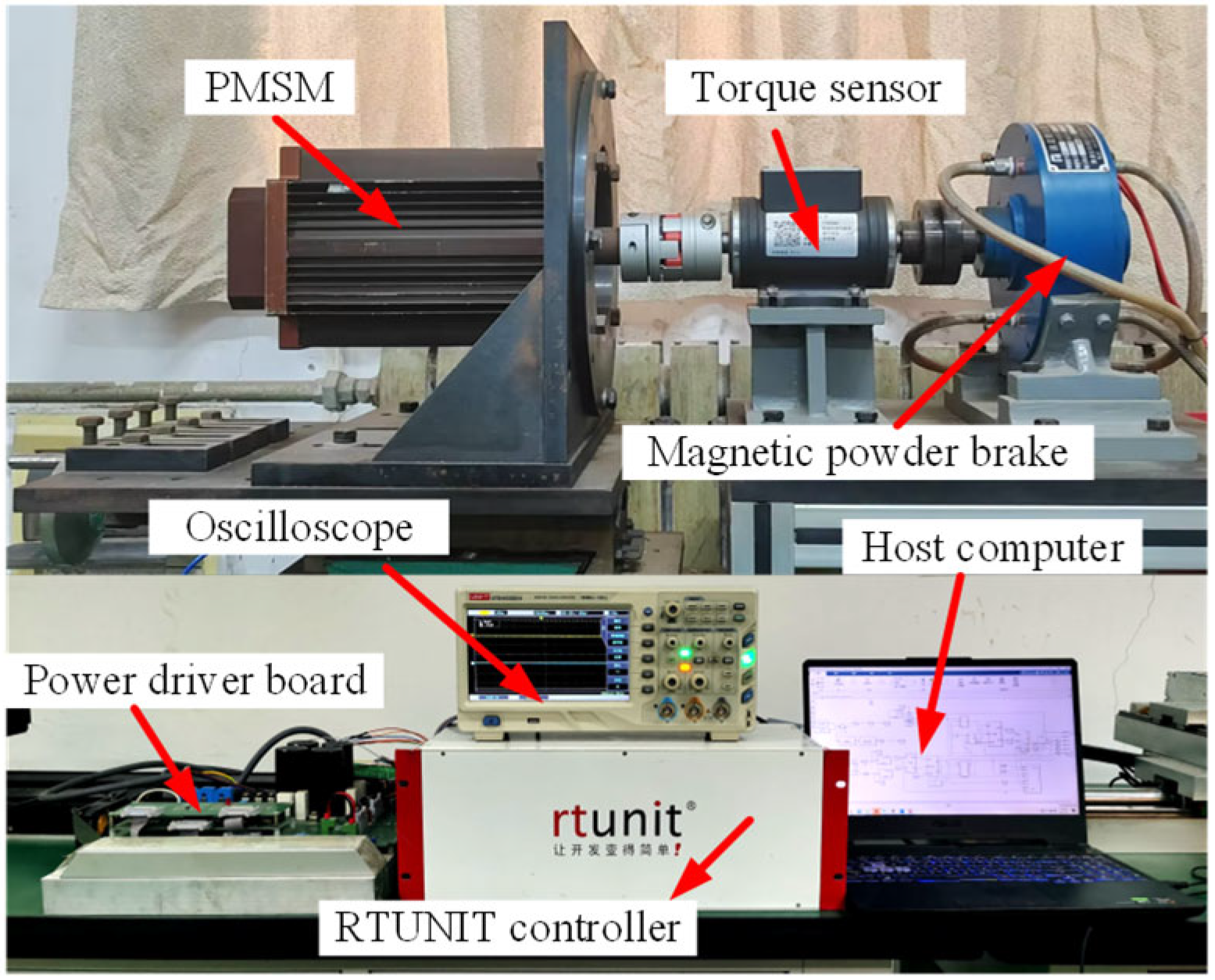
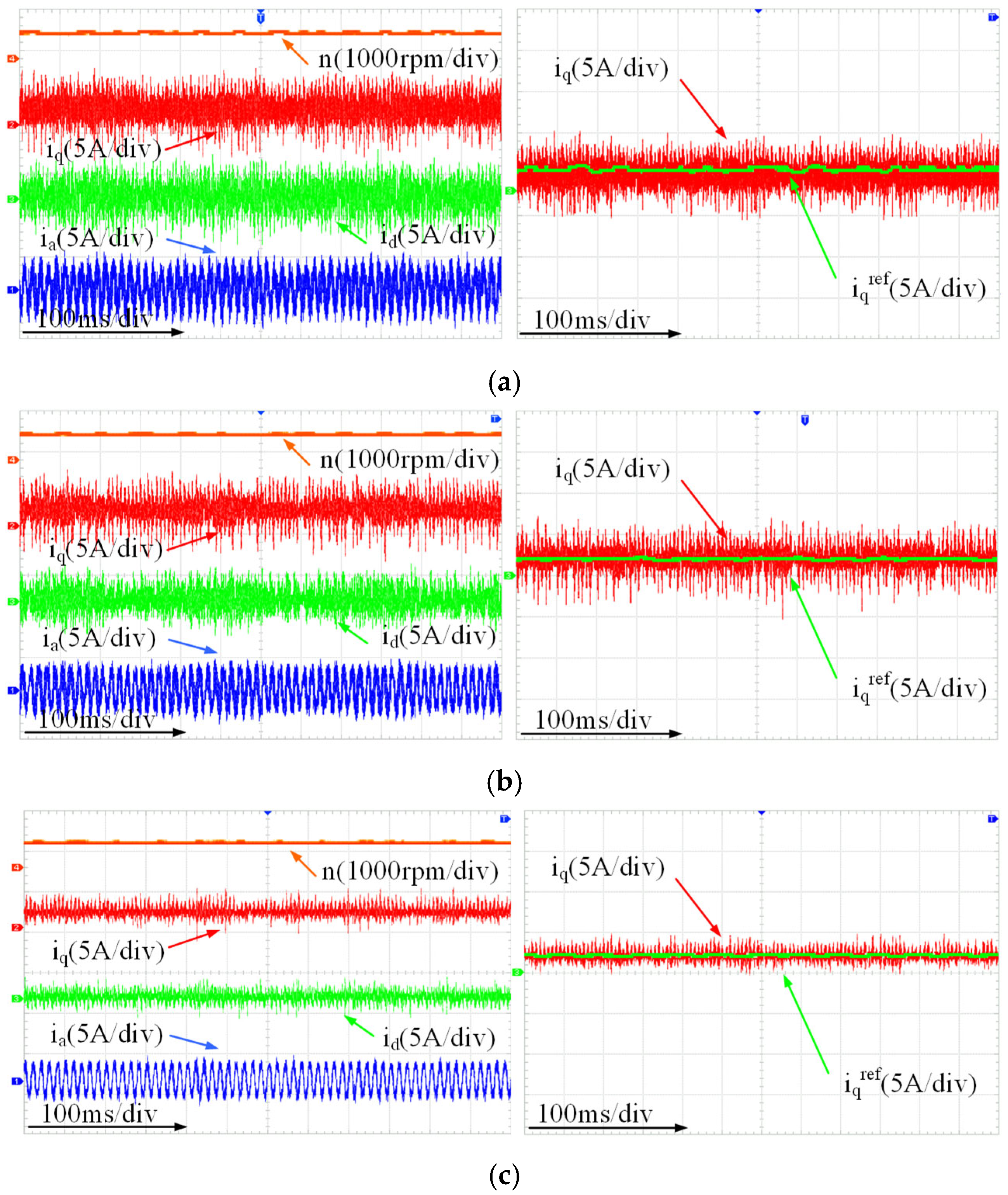
(3) To conduct systematic experimental validation of the proposed control strategy, an experimental platform was established, featuring a TMS320C28346 DSP as the core controller and an Rtunit drive module. Comprehensive simulation and experimental results collectively demonstrate that the proposed control strategy delivers superior steady-state precision and dynamic responsiveness under a wide range of operating conditions.
3. Design of VPA-DV-MPCC System Based on IEAL-SMC
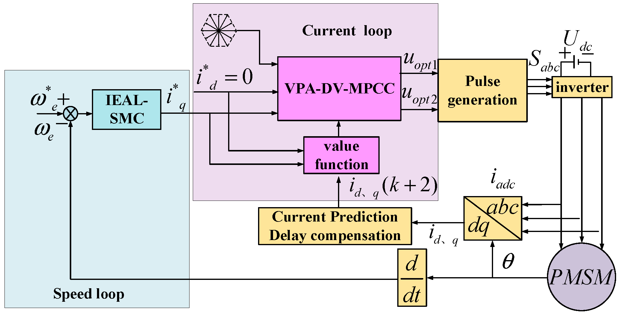
The system architecture of the proposed IEAL-SMC-based VPA-DV-MPCC scheme is illustrated in
Figure 1. Within the current control loop, a voltage phase angle decision mechanism enables optimal vector selection from the finite control set through rapid optimization, thereby enhancing the efficiency of voltage vector selection. In the speed regulation loop, the IEAL-SMC controller, with its superior robustness, effectively attenuates the impact of external disturbances—including load variations—while ensuring stable speed tracking performance.
3.1. Design of VPA-DV-MPCC Algorithm
The conventional DV-MPCC algorithm employs an exhaustive search strategy, which evaluates all eight basic voltage vectors by substituting their corresponding and values into the cost function to identify the optimal uopt1 and suboptimal uopt2 vectors that minimize and . However, this approach results in the computational burden increasing linearly with the number of voltage vectors. To address this limitation, this paper proposes a voltage phase angle decision mechanism that leverages the q-axis current reference (iq*) from the speed controller to predetermine the sector location of uopt1 before vector selection. This innovative approach effectively confines the candidate vectors to adjacent sectors, followed by selection of uopt2 based on the minimum switching loss principle, thereby significantly improving voltage vector selection efficiency.
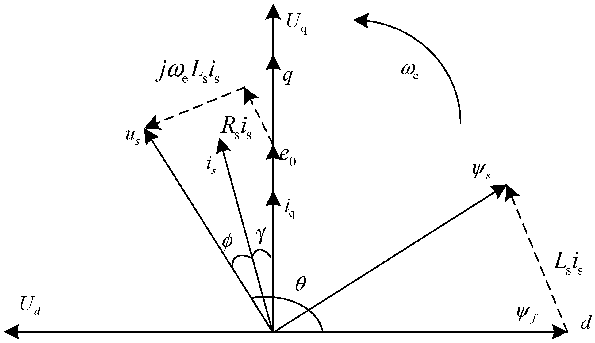
Figure 2 shows the space vector diagram of a surface-mounted PMSM considering resistance voltage drop. Here,
represents the power factor angle;
denotes the current angle;
indicates the stator flux linkage vector, and
is the angle rotating counterclockwise from the positive d-axis to the voltage vector
us. Since this study adopts the
id = 0 control strategy, the current vector is aligned with the q-axis (
is =
iq), as shown in the diagram. Consequently, the d-q axis voltage components can be expressed as follows:
By combining Equations (6) and (7) with the desired q-axis current
iq* generated by the IEAL-SMC controller, the phase angle
of the stator voltage vector
us can be derived as follows:
By substituting the q-axis current reference
iq* calculated from the speed-loop sliding mode controller into Equation (8), the magnitude of the voltage vector angle can be obtained. Since the actual
is negative in this operating condition, a direct calculation would yield an angle in the first quadrant. Therefore, a supplementary angle correction is required, and the actual phase angle
is determined as follows:
Considering the deviation between the actual phase angle
and the reference angle
that degrades current dynamic response, the cost function accounting for phase angle optimization effects on vector selection can be defined as follows:
In the equation, ; and represent the d-axis and q-axis current reference values, respectively; and denotes the voltage phase angle tracking weight factor, with its value constrained within the range of 0.1–0.5. This specific range is determined based on two key considerations.
From the control objective standpoint, the lower bound is set to 0.1 to ensure that the phase angle optimization term within the cost function can exert a meaningful influence on voltage vector selection. This prevents the phase angle information from being overlooked due to an excessively small weighting. Specifically, when is less than 0.1, the phase angle’s guiding effect on vector selection becomes negligible, resulting in diminished accuracy of voltage vector selection and an elevation in current THD.
The upper bound is set to 0.5 to avoid the phase angle term dominating the optimization process by occupying an overly large proportion in the cost function, which would otherwise unduly compromise current tracking performance. Experimental observations indicate that when exceeds 0.5, the current tracking error increases significantly, failing to ensure adequate tracking of d-q axis currents to their respective reference commands. Conversely, when is within the 0.5 limit, it not only preserves the beneficial role of phase angle decision-making but also maintains the core priority of current tracking.
3.2. Figures, Tables, and Schemes
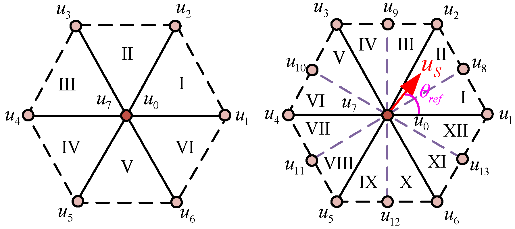
The voltage vector sector division method is illustrated in
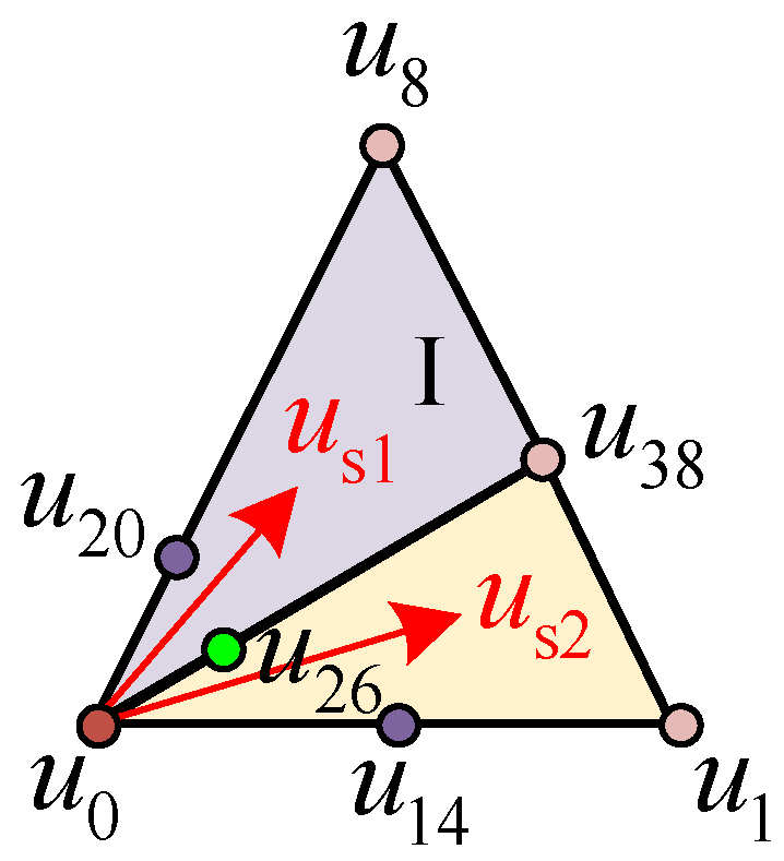
Figure 3. Building upon the conventional six-sector framework, each control cycle is equally partitioned into two segments, thereby expanding the number of voltage vector sectors from six to twelve (Sectors I–XII). For clarity of presentation,
.
is calculated via Equation (8) and corrected by angle compensation through Equation (9), ensuring its continuity in physical meaning. To further enhance robustness:
(1) Sector subdivision and buffer design: The traditional 6 sectors are subdivided into 12 sectors (
Figure 3), and in the algorithm design, ±5° buffer zones are set at the boundaries of each sub-sector (e.g., 30°, 60°) to cope with minor deviations of
that may be caused by transient fluctuations.
(2) Boundary collaborative evaluation: When approaches the sector boundaries or enters the buffer zones, the algorithm synchronously evaluates the candidate vectors of adjacent sectors, avoiding misselection that might result from single-sector judgment.
The conventional DV-MPCC algorithm is constrained to selecting voltage vectors exclusively from the eight basic inverter voltage vectors. This limitation often results in considerable current tracking errors and a heightened susceptibility to local optimal solutions, primarily due to inadequate vector resolution in the FCS. While expanding the number of candidate voltage vectors can enhance control accuracy, an excessive increase in vector quantity inevitably introduces three critical drawbacks: heightened computational overhead, elevated hardware costs, and exacerbated inverter switching losses. To strike a balanced trade-off between control performance and hardware economic feasibility, this study proposes a voltage phase angle decision-based strategy that constructs an optimized FCS consisting of 50 voltage vectors. This design not only preserves high control precision but also avoids the overconsumption of hardware resources—addressing the core contradiction between performance enhancement and implementation costs in conventional DV-MPCC.
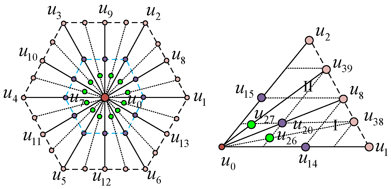
Figure 4 presents the spatial distribution and local magnification of voltage vectors in the extended finite control set, which includes 8 basic voltage vectors (
u0 to
u7) and 42 virtual voltage vectors (
u8 to
u49). The virtual vectors are synthesized from the basic voltage vectors. These synthesized vectors are generated through duty cycle combinations of adjacent basic voltage vectors (including zero vectors), with the core formula given as follows:
ux and
uy are adjacent active basic voltage vectors (e.g.,
u1,
u2), while
u0 denotes the zero-voltage vector (
u0 or
u7). The duty cycle constraints satisfy
d1 +
d2 +
d3 = 1 with
di ∈ [0, 1]. A quarter-step precision is employed for duty cycle partitioning (e.g., 1/2, 1/4, 3/4), which ensures vector resolution while avoiding excessive computational burden caused by over-subdivision. Taking Sectors I and II in
Figure 4 as examples, the specific synthesis process is as follows:
- (1)
Synthesized vectors within sectors:
By uniformly adjusting the duty cycles of active vectors (e.g., in proportions of 1/4, 1/2, 3/4), the synthesized vectors are distributed in a gradient pattern within the sector, ensuring minimal approximation error for any reference vector. For example, u8 = 1/2u1 + 1/2u2, u38 = 3/4u1 + 1/4u2, and u39 = 3/4u2 + 1/4u1 are all synthesized by adjacent active basic vectors in different proportions without introducing zero vectors. The duty cycle design aims to refine the vector density inside the sector and enhance the approximation accuracy of the reference voltage vector. Among them, u38 and u39 are biased toward the directions of u1 and u2, respectively, which can cover the requirements of reference vectors with different phases within the sector.
- (2)
Sector boundary transition vectors at sector boundaries:
To address the current harmonic issues prone to occur in boundary regions, the synthesized vectors must balance “smooth switching” and “switching loss suppression”. Therefore, zero vectors are introduced with adjusted duty cycles (e.g., the zero vector accounts for 1/2 in u20), which not only reduces current fluctuations caused by vector mutations but also lowers the switching frequency through zero vectors. Specific synthesis methods are as follows: u20 = 1/4u1 + 1/4u2 + 1/2u0, u26 = 1/4u1 + 1/8u2 + 5/8u0, u14 = 1/2u1 + 1/2u0, and u15 = 1/2u2 + 1/2u0. These synthesized vectors incorporate zero vectors (u0) into active vectors and adopt asymmetric duty cycle designs (e.g., zero vector proportions of 1/2 and 5/8) to accommodate angular deviations at sector boundaries, thereby optimizing the smoothness of vector switching. While retaining directional control capability, the rational configuration of zero vector proportions helps to reduce switching frequency and effectively suppress steady-state current ripples.
The optimal voltage vector selection strategy operates as follows
Figure 5. If the optimal phase angle (
) is located within Sector I, the algorithm first evaluates two conditional branches: If g(
u1) > g(
u8), it identifies
uₒₚₜ
1 by comparing g(
u8), g(
u38), g(
u20), and g(
u26) while excluding zero vectors; otherwise,
uₒₚₜ
1 is determined through comparison of g(
u1), g(
u26), g(
u38), and g(
u14). Subsequently, adhering to the minimum switching loss principle,
uₒₚₜ
2 is selected from
uₒₚₜ
1’s adjacent vectors (e.g., choosing between
u14,
u0, and
u20 when
uₒₚₜ
1 =
u26). Finally, the target voltage is synthesized by optimally allocating the duty cycles of these two optimal vectors.
Based on the aforementioned control strategies, a comparative analysis of voltage vector selection efficiency was conducted among MPCC, DV-MPCC, and VPA-DV-MPCC. Both
u0 and
u7 are zero-voltage vectors, which are essentially distinguished only by their different directions and thus classified into the same category. In the DV-MPCC control strategy, the selection of
uopt1 considers only the active voltage vectors while disregarding the zero-voltage vectors, whereas the selection process of
uopt2 incorporates the zero-voltage vectors. As shown in
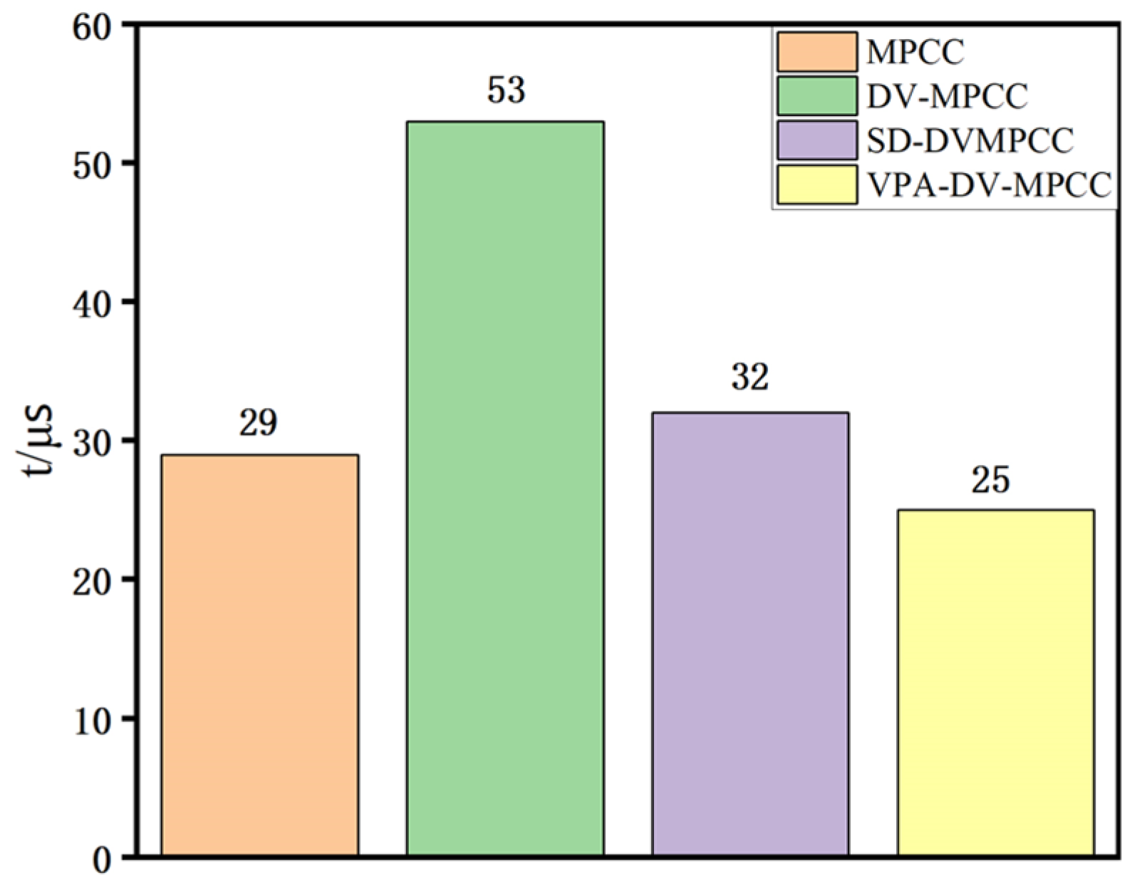
Table 1, the proposed VPA-DV-MPCC algorithm expands the candidate voltage vector range while requiring only 7 computations to determine the optimal voltage vector, significantly reducing computational complexity.
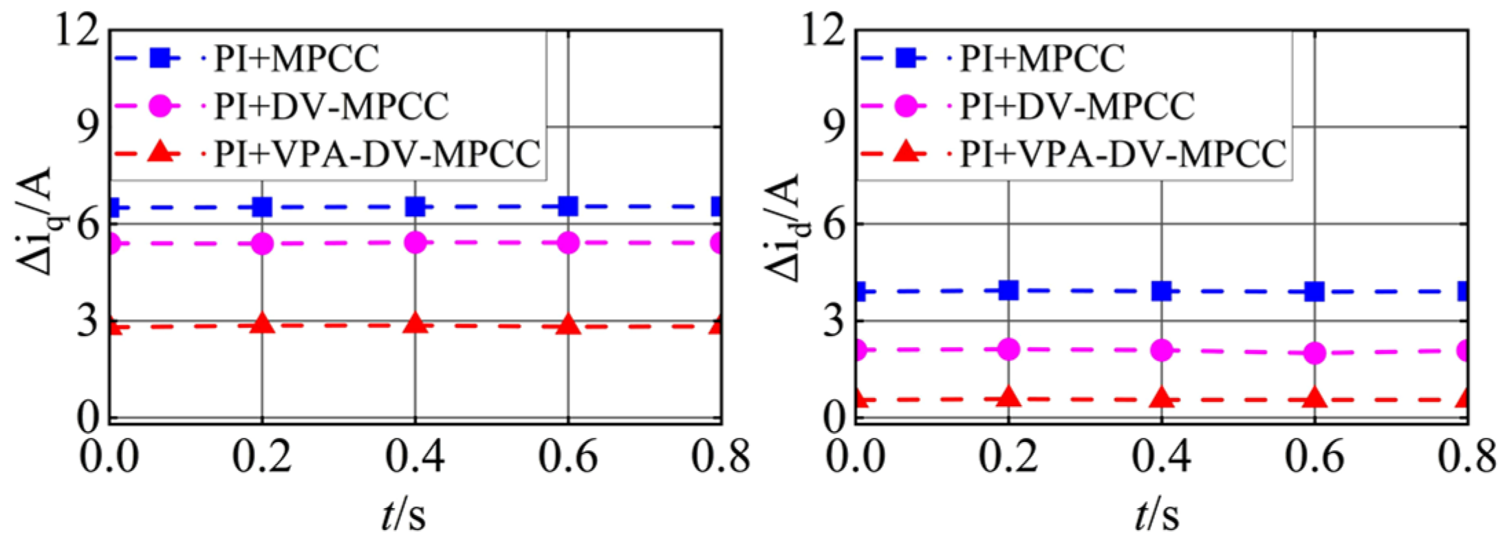
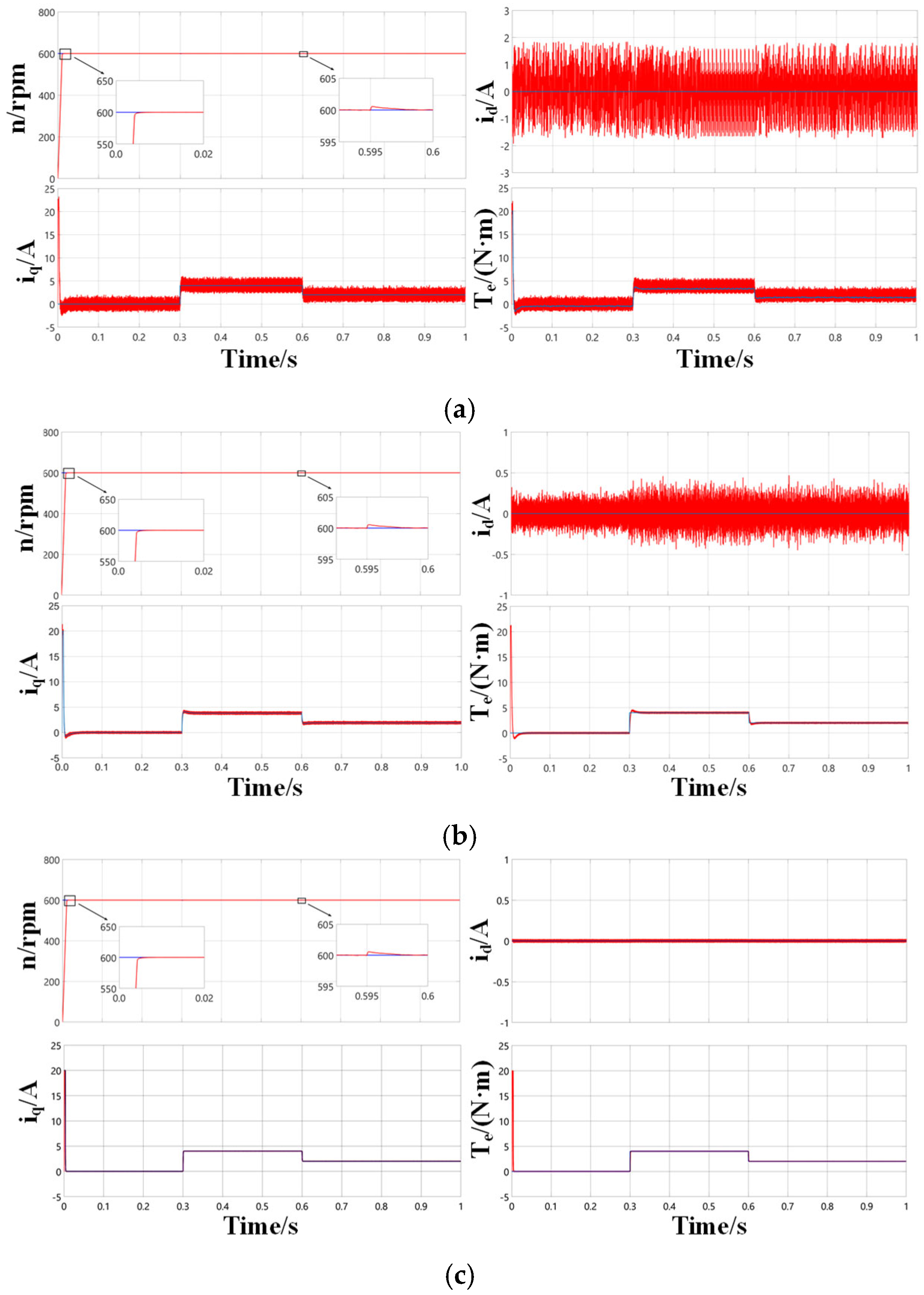
To preliminarily validate the feasibility of the proposed VPA-DV-MPCC algorithm, comparative simulations of three distinct control strategies were performed under identical PI parameter configurations, with the corresponding results presented in
Figure 6. These simulation results illustrate that the proposed VPA-DV-MPCC algorithm achieves a further reduction in the ripple of both the quadrature-axis current and direct-axis current compared to the other two strategies.
Based on the deadbeat control principle for the q-axis current, the time allocation between
uopt1 and
ui during the sampling period is optimized. With the inclusion of one-step delay compensation,
iq reaches its reference value
iq* at the (
k + 2)th instant, expressed as:
The duration of
uopt1 can be obtained as
In the given expression, sopt1 and si denote the slopes of the q-axis current under the influence of voltage vectors uopt1 and ui, respectively, where ui represents the i-th voltage vector with an application duration of Ts − topt1.
sopt1 and
si can be expressed as:
In the equation, uq_opt1 represents the q-axis component of uopt1, uqi denotes the q-axis component of the -th candidate voltage vector, and s0 is the slope of current iq when the zero-voltage vector is applied.
3.3. Design of IEAL-SMC
To effectively reconcile the conflict between convergence speed and chattering suppression, this paper incorporates the softsign function into the exponential reaching law-based sliding mode control (ERL-SMC), thus proposing an IEAL-SMC. The softsign function is mathematically expressed as follows:
where
is the smoothing parameter factor, with
.
The exponential term enables the system states to converge rapidly toward the sliding surface when they are far from the equilibrium point. However, ideal SMC theoretically necessitates switching at an infinite frequency. The sign function exhibits a discontinuous characteristic at the zero-crossing point, which introduces switching discontinuities in the vicinity of the sliding surface—this discontinuity is the fundamental cause of the chattering phenomenon.
To mitigate chattering phenomena, several continuous switching functions have been adopted, including the saturation function, hyperbolic tangent function, and sigmoid function [
45].
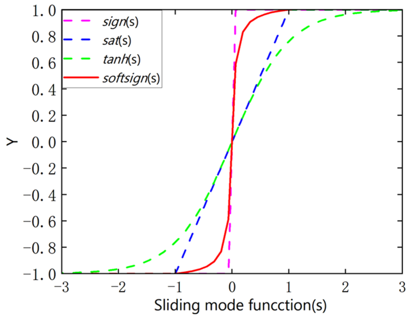
Figure 7 provides a comparative illustration of the characteristics of four switching functions: sign(s), sat(s), tanh(s), and the proposed softsign(s). As
diminishes toward zero, distinct convergence behaviors become evident: sat(s) exhibits linear convergence, sign(s) displays abrupt discontinuous switching, while both tanh(s) and softsign(s) demonstrate smooth asymptotic convergence within the boundary layer, with the proposed softsign(s) maintaining superior continuity across the entire transition region. This comparative analysis quantitatively confirms that softsign(s) effectively integrates the rapid convergence capability of sign(s) with the smooth transition characteristics of tanh(s), thereby achieving an optimal balance between dynamic responsiveness and chattering suppression.
Figure 8 provides a comprehensive performance comparison of the switching functions through numerical analysis. The results indicate that while the sign(s) function achieves the fastest convergence time, it induces significant chattering effects. In contrast, both the sat(s) and tanh(s) functions effectively smooth the system output and attenuate chattering, but this comes at the cost of sacrificing guaranteed finite-time convergence and control precision. This comparative study quantitatively reveals the inherent trade-off between convergence speed and control smoothness in switching function selection. In contrast, the proposed softsign(s) function generates smoother control signals while simultaneously ensuring three key performance metrics: (1) finite-time convergence, (2) effective chattering suppression, and (3) superior tracking performance.
To further enhance the adaptive capability of the smoothing factor, we design
to dynamically vary with
:
To achieve adaptive smoothing, the parameter ν is dynamically adjusted within the range [,], where represents the minimum smoothing factor (activated when the system state is far from the sliding surface to ensure fast convergence), denotes the maximum smoothing factor (engaged near the sliding surface to suppress chattering), and serves as the transition rate parameter that regulates the adaptation speed between these boundary values.
and are not fixed values but vary with the sliding mode surface according to Equation (16). Specifically, (minimum smoothing factor) and (maximum smoothing factor) correspond to two operating conditions: “far from the sliding mode surface” and “close to the sliding mode surface”, respectively. The initial value of ( = 0.5) ensures that the softsign function approximates the sign function when far from the sliding mode surface (enabling fast convergence), while the initial value of ( = 5) guarantees the linearization of the function when close to the sliding mode surface (suppressing chattering). The dynamic value ranges of both parameters are determined through repeated simulation verification.
If is too small (e.g., <0.1), it may lead to excessive amplitude of the control input when far from the sliding mode surface, exacerbating system chattering. Conversely, if is too large (e.g., >1.0), it will weaken the fast approaching characteristic and prolong the response time.
If is too small (e.g., <3.0), the smoothing effect when approaching the sliding mode surface will be insufficient, resulting in reduced chattering suppression capability. If is too large (e.g., >10.0), it may cause excessive smoothing of the control input, sacrificing dynamic response speed (e.g., prolonged recovery time during load mutations).
Similarly, fluctuations in ζ (transition speed adjustment parameter) have an even smaller impact on performance: when ζ varies within the range of 0.6–1.0, the system overshoot is always controlled within a reasonable range.
The output amplitude of the softsign function decreases as s diminishes, enabling dynamic adjustment based on its magnitude. When far from the sliding surface (where is large), the dynamic response speed is prioritized, and the smoothing parameter factor gradually decreases, allowing the function to approximate softsign(s) ≈ sign(s)/. Conversely, when approaching the sliding surface (where is small), the smoothing parameter factor gradually increases, and the function behaves as softsign(s) ≈, resulting in linear control that is closer to saturation. This ensures smoother control signals, effectively suppressing chattering and enhancing control performance.
Additionally, the gradient decay of the softsign function occurs at a polynomial level, meaning its gradient descent rate is relatively slow—this characteristic enables it to maintain a certain gradient even for large input values. The function retains smoothness and continuity while utilizing only basic operations: absolute value, addition, and division, thus avoiding computationally expensive exponential calculations. In summary, the softsign function exhibits global convergence properties. By incorporating it into the exponential reaching law, an IEAL-SMC is constructed, which enhances control performance while effectively mitigating chattering effects.
The expression of the improved exponential reaching law is given as follows:
The expression of the improved exponential reaching law can be described as follows: , , where s represents the sliding surface; x1 denotes the system state; is the exponential component; serves as the terminal sliding mode term; and is the system state variable. The parameter represents an adjustable term, while denotes the linear gain coefficient.
When |s| is large, ks ≈ , which is significantly greater than the original gain k, ensuring the system has smaller reaching time and stronger robustness. The addition of the terminal term enables the system to achieve better dynamic response performance when is relatively large. When |s| is small, ks ≈ .
The expression for the variable term is as follows:
In the equation, can serve as the coefficient of the variable term.
The variable switching gain can consistently remain smaller than the original gain k, effectively suppressing system chattering. When ks ≈ , under the action of the control law, the system state gradually approaches zero, causing ks to likewise converge toward zero, and the system trajectory progressively approaches the sliding surface. Therefore, the proposed improved reaching law-based controller exhibits dynamic adaptability to both system states and variations in the sliding surface s, thereby achieving enhanced control performance.
To avoid involving the second derivative of variables in the controller design, an integral sliding surface is adopted, and the velocity tracking error is defined as follows:
The sliding surface is expressed as:
Differentiating
s with respect to time yields:
The dynamic equation of the PMSM is expressed as:
Combining the above equations, the sliding mode control law can be derived as:
Define the Lyapunov function as:
The derivative of
Vc is calculated as:
Combining the above equations allows for the verification of the Lyapunov theorem:
The first term, both and , is less than or equal to 0 (equal to 0 if and only if = 0). The second term, is less than or equal to 0. When , , ensuring convergence within a finite time. Therefore, for all s ≠ 0. Based on the Lyapunov stability criterion, the designed closed-loop control system exhibits globally asymptotic stability characteristics.
3.4. Proof of Finite-Time Convergence for the Softsign Function
To further illustrate the finite-time convergence property of the softsign function, we adopt the “staged parameter dynamic approximation + Lyapunov function derivative constraint” method, the parameters are adjusted in two phases—i.e., when the system state is far from the sliding surface and when it is close to the sliding surface—by leveraging the reaching law characteristics of the FSTA. The finite-time convergence is then determined using (where > 0 and (0,1)).
Drawing on the “terminal sliding mode term-dominated attenuation + integral calculation for convergence time” approach, the integral formula is derived by exploiting the terminal term characteristic ( (0,1)) of the NFTSMC. Specifically, minor linear terms are neglected, and only the dominant attenuation term is retained during the derivation process.
Derivation of Finite-Time Convergence Time (Stage-Wise Analysis)
- (1)
Stage 1: Large () (Fast Approaching Stage, Far from the Sliding Surface)
When is large (the system is in the initial stage of sliding mode control and far from the sliding surface equilibrium point):
For the dynamic smoothing parameter
: Since
is large,
, so
and thus
. At this point, the softsign function is approximated as follows:
where
is the sign function, and the approximation
holds because
.
For the adaptive control gain
: Since
is large,
,
. Thus,
,
. Substituting the above approximations into the reaching law, the expression of
is simplified as follows:
Lyapunov Stability Analysis
Here, V > 0 for all , and V = 0 if and only if = 0, satisfying the positive definiteness requirement of the Lyapunov function.
Taking the time derivative of V and substituting the simplified :.
Using the property
,
, the derivative is further simplified as follows:
For large
, the linear term 2
k1V has a much weaker decay effect compared to the nonlinear term
(0,1). Since the terminal term is a nonlinear fast-decaying term, the linear term can be neglected, yielding:
where
. Moreover,
(0,1) satisfies the
criterion for finite-time convergence.
Calculation of Convergence Time t1:
Let
be the initial value of the Lyapunov function at the start of Stage 1 (where
denotes the initial value of the sliding surface), and the termination Lyapunov value is
V1 (corresponding to the state transitioning from the far phase to the near phase). Integrate
.
Using the integral formula
, the calculation yields the following:
By substituting
and
, the convergence time
t1 is finally derived as follows:
where
denotes the sliding surface value at the termination of the far phase and
, it can be observed that
t1 is a finite value.
- (2)
Stage 2: Small (Chattering Suppression Stage, Close to the Sliding Surface)
Since is small, ,. Thus, , and , the exponential term , ,,.
Substituting the above expressions into the reaching law:
Since
is small,
, thus
. Substituting (the aforementioned expression/variable) and simplifying yields the following:
A quadratic Lyapunov function
is still selected, and its time derivative is given by
. Substituting the simplified
into the expression, and using
, the following is obtained:
Since |s| is small, the attenuation effect of the linear term
is much weaker than that of the terminal term
(0,1),
(1,1.5) (where the terminal term is a high-order nonlinear attenuation term). Thus, neglecting the linear term yields the following:
where
(which satisfies the “terminal term-dominated attenuation” condition for finite-time convergence).
Calculation of convergence time t2:
Let the initial Lyapunov value of the near phase be
and the terminal Lyapunov value be
with the corresponding
. Integrate
(refer to
Section 4.1 NFTSMDO Convergence Time Integration:
Using the integral formula
, the calculation yields the following:
By substituting
and
, the expression for convergence time
t2 is finally derived as follows:
It can be observed that t2 is a finite value, which aligns with the design objective of this paper: “suppressing chattering while achieving fast convergence when approaching the sliding surface”.
The total convergence time is given by
, which satisfies the following:
After simplification, the result is obtained as follows:
Since both t1 and t2 are finite values, T is also a finite value; thus, the softsign function satisfies the finite-time convergence property.
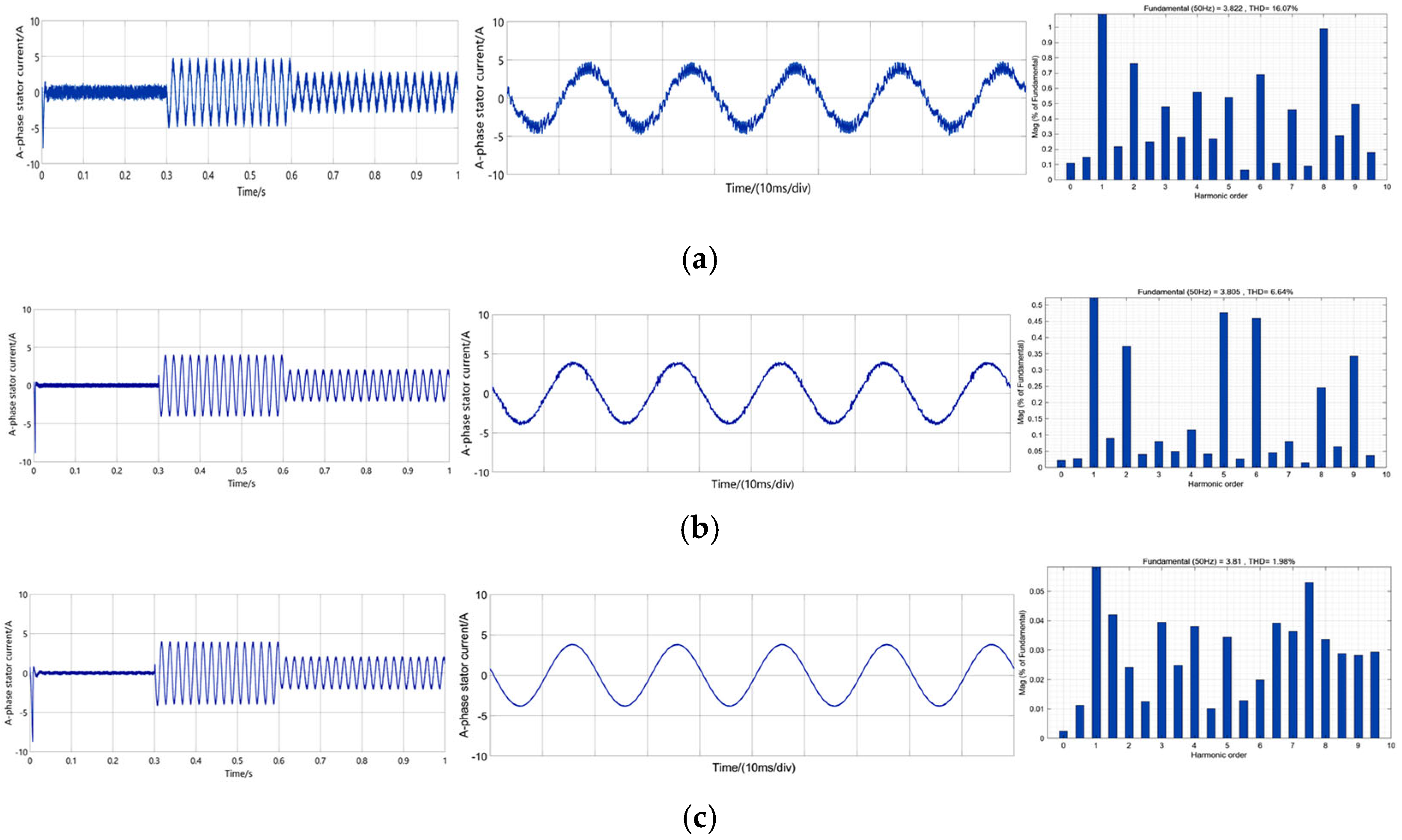
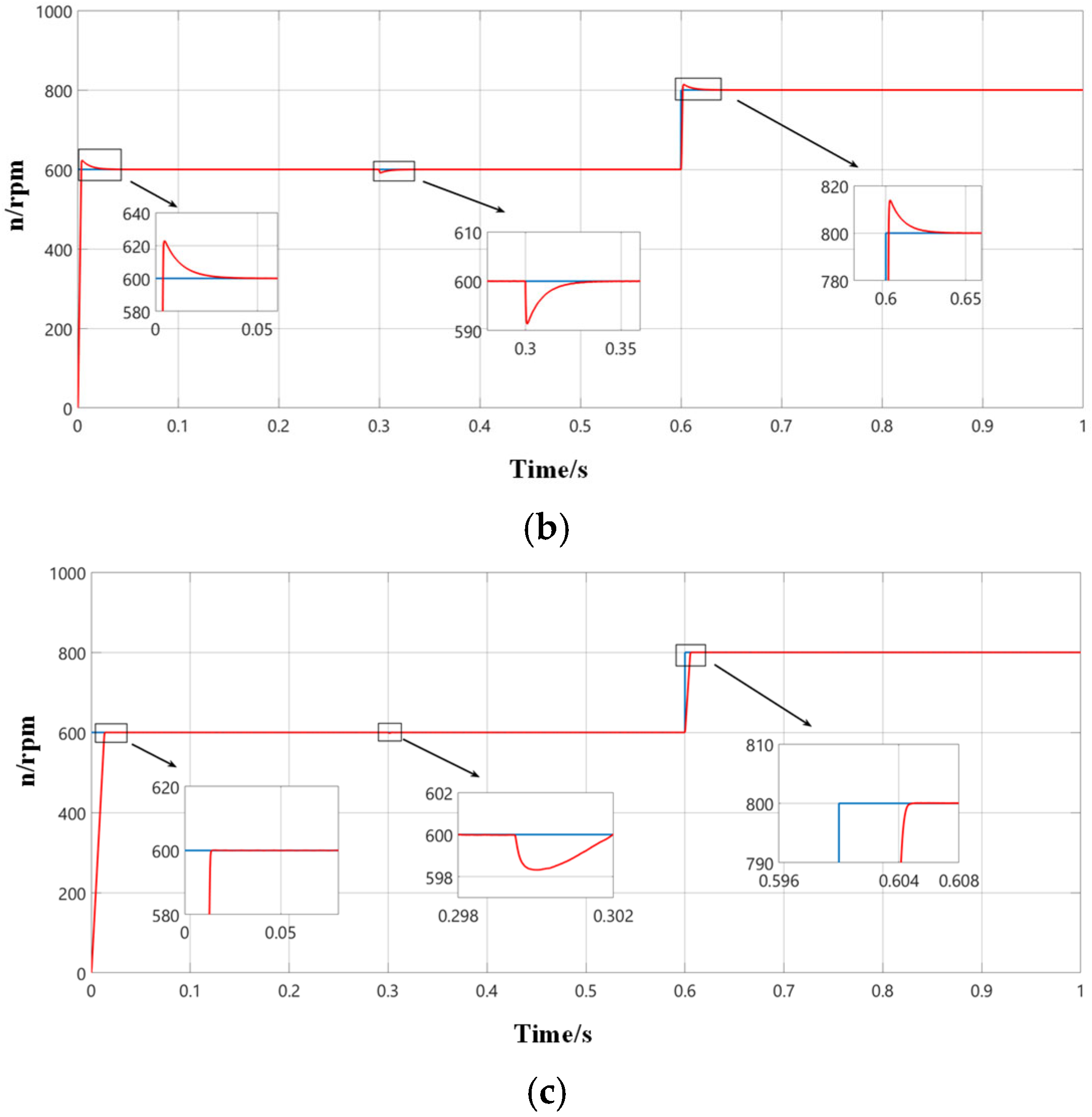
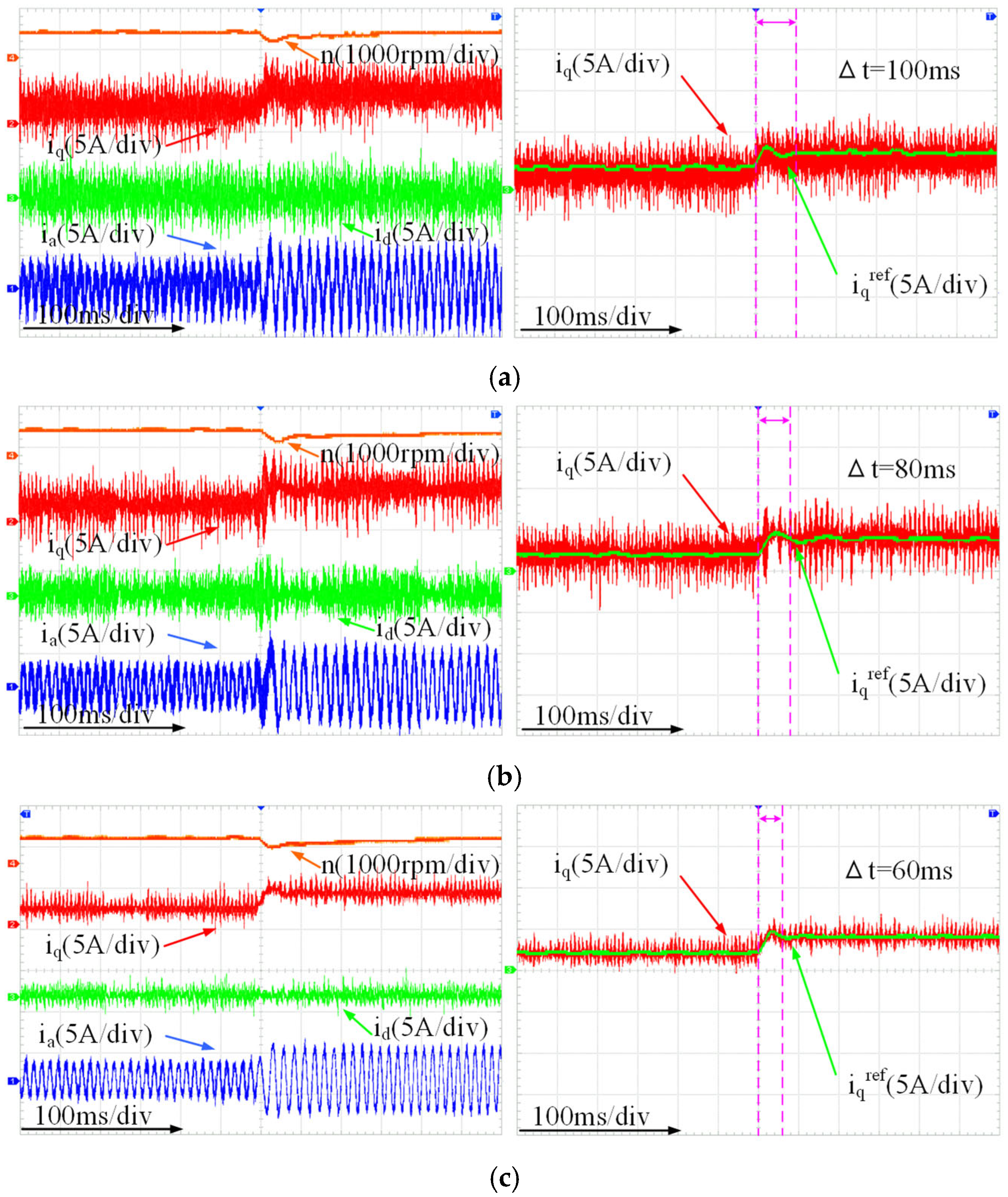
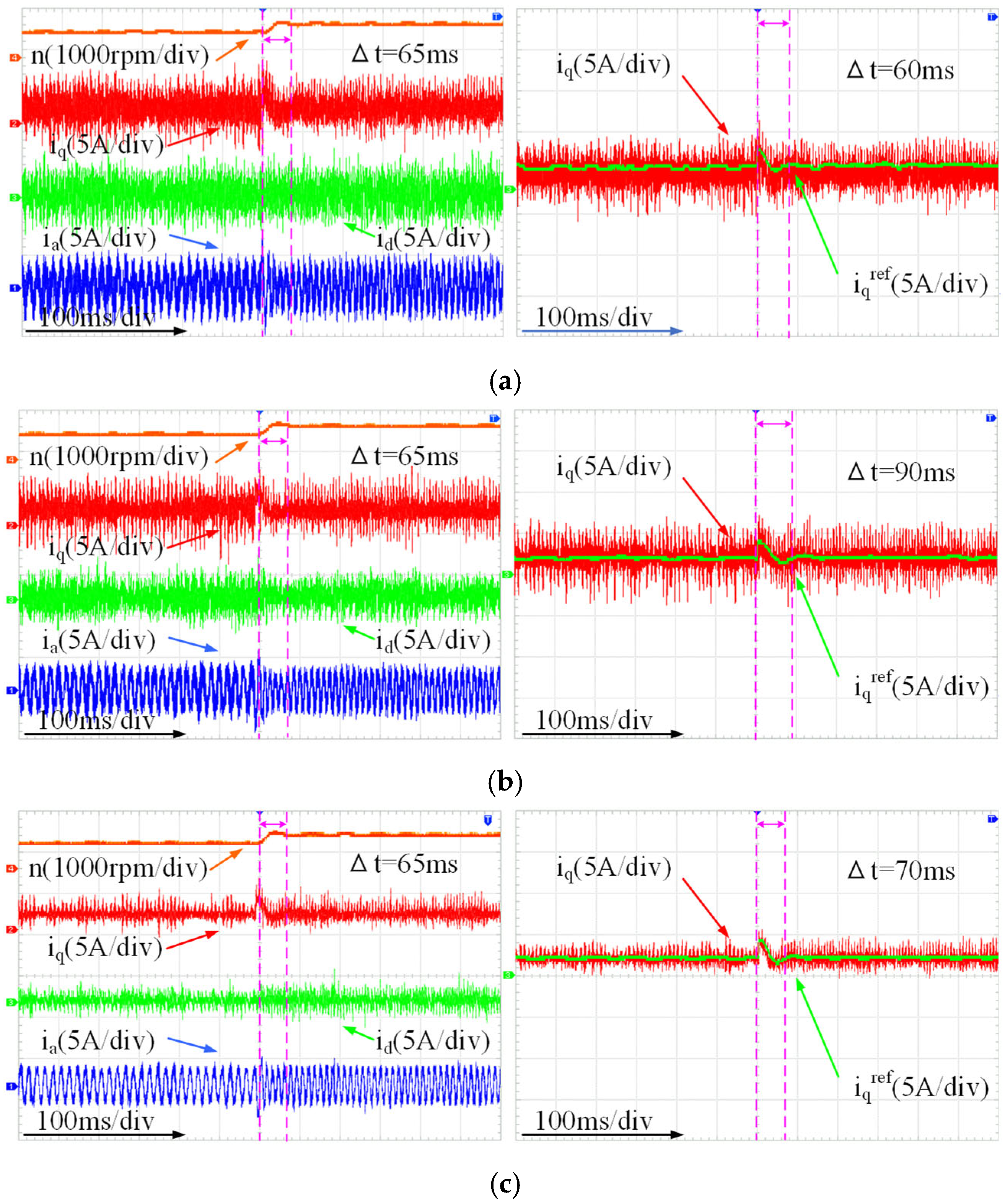
To validate the feasibility of the proposed IEAL-SMC, a comparative analysis was conducted among three distinct control strategies: PI control, conventional SMC, and the proposed IEAL-SMC. In this analysis, subfigures (a–c) correspond to the speed loop adopting PI control, SMC, and IEAL-SMC, respectively. The curves in the figure are differentiated by the control methods applied in the current loop: blue represents MPCC, green denotes DV-MPCC, and red indicates VPA-DV-MPCC. As illustrated in
Figure 9, the results confirm that the proposed IEAL-SMC achieves a further reduction in speed fluctuations.
