1. Introduction
With the burgeoning of an aging society, the challenge of nursing transfer in the daily lives of lower limb-disabled elderly individuals has become increasingly pronounced [
1]. For instance, elderly individuals often require assistance when transitioning from a bed to a toilet [
2]. Traditionally, this process necessitates a considerable expenditure of physical strength from caregivers, potentially leading to musculoskeletal disorders [
3]. To address this issue, various nursing transfer devices or robots have been developed. For example, C-Pam [
4] uses a conveyor belt to transfer the care recipients from bed to stretcher; RI-MAN [
5,
6,
7,
8], a two-armed robot, can carry care recipients in its arms. However, these nursing transfer devices focus primarily on ensuring that the origin and destination meet the expected requirements [
9]. There is a lack of research on comfort during nursing transfer process. Given the weak mobility of individuals with lower limb disabilities, it is necessary to study quantitative assessment and effective improvement of the comfort during human–robot interaction to avoid secondary injuries.
On the one hand, subjective comfort questionnaires are commonly used to quantify comfort levels. Greenhalgh et al. [
10] proposed a robot-assisted transfer device called RATD, and then verified that its comfort is better than the traditional mechanical floor lift via the subjective evaluation of participants. Velagapudi and Ray [
11] developed a reliable motorcycle seat comfort questionnaire to assess the comfort of motorcycle seats and to provide a basis for further research into motorcycle seat comfort. Bouwens et al. [
12] compared interactive aircraft seats with current economy class seats based on subjective passenger ratings and verified that passengers experienced better comfort in interactive aircraft seats. However, while these methods are simple and efficient, they are susceptible to bias, requiring objective physiological indicators for validation.
Human comfort is closely related to various physiological indicators. Currently, common physiological indicators used to assess comfort in human–machine interaction include contact pressure and surface electromyography (sEMG). Ge et al. [
13] analyzed the comfort of head-mounted displays across four dimensions: fit, load-bearing comfort, force comfort, and thermal–humidity comfort. By integrating sEMG signals, contact pressure, and subjective feedback, a relatively comprehensive comfort evaluation system was established. Li [
14] combined seat surface pressure experiments with subjective evaluations, utilizing a backpropagation neural network (BPNN) to develop a wheelchair comfort evaluation model, enabling fast and efficient prediction of tactile comfort in wheelchairs. Cattarello et al. [
15] used high-density surface electromyography (HD-sEMG), biomechanics, and comfort indices to investigate the effects of different chairs on the posture of violin and viola players. Although physiological indicators have been widely used in comfort analysis across various human–machine interaction studies, their application in evaluating and controlling comfort in nursing transfer robots remains limited.
On the other hand, to improve comfort during human–machine interaction, many studies have employed passive methods, such as installing soft skins [
16]. Sutrisno et al. [
17] applied a quasi-passive variable-stiffness spring to a lower limb exoskeleton mechanism, to improve its comfort. Song et al. [
18] investigated a crank-slider series elastic actuator, which can be used as a compact exoskeleton joint module. While passive cushioning can reduce shock and pressure, its limited deformation range may not accommodate sudden changes in a patient’s posture during interaction. Therefore, the motion of the nursing transfer robot should be actively adjusted.
Currently, active comfort control methods have been applied in various fields. Jayachandran et al. [
19] proposed an automotive suspension system with variable stiffness and damping, demonstrating improved ride comfort and handling. Ugurlu et al. [
20] presented a locomotion controller for lower limb exoskeletons that manages the force–position trade-off, resulting in enhanced comfort. Khoshdel et al. [
21] presented electromyogram-based robust impedance control for a rehabilitation robot, to reduce the care recipient’s discomfort. However, there is limited research on active comfort control of nursing transfer robots.
Based on the background described above, this study aims to enhance the human–robot interaction comfort of backpack-type carrying robots by developing a neural network-based active control strategy. To achieve this objective, it is essential to first establish a quantitative definition of “comfort” in order to objectively evaluate the effectiveness of different control strategies. Comfort can be primarily assessed using two quantitative metrics: subjective ratings (after completing each specific carrying task, participants provide a subjective comfort score based on their personal experience) and electromyographic (sEMG) signals (the activation level of the latissimus dorsi is used as a core physiological indicator).
Specifically, the muscle activation data derived from sEMG signals are directly integrated into the objective function of a Genetic Algorithm (GA)-based optimization control, enabling real-time adaptation of the chest plate angle. In contrast, subjective ratings are used as a validation tool to ensure that the optimization outcomes not only perform well in terms of technical metrics but also genuinely improve the user’s perceptual experience.
While sEMG signals provide objective information regarding muscle status and potential fatigue, subjective ratings directly reflect individual user perception. The ultimate goal is to identify an optimal solution that simultaneously maintains muscles in an efficient working state (i.e., minimizing fatigue) and satisfies users’ subjective comfort requirements. By integrating these two complementary approaches, this study enables a more accurate understanding and enhancement of human–robot interaction comfort during load-carrying tasks.
The structure of the paper is arranged as follows: First, the physical structure and motion behaviors of the robot are described. Then, based on kinematic analysis, the robot trajectory is planned for experimentation. A back-carrying experiment is performed based on a defined trajectory, and human–robot contact forces, chest holder rotation angles, and activation of the main back muscles are recorded. A muscle activation prediction model is then established using an Online Sequential Extreme Learning Machine (OS-ELM). Using the pre-trained ELM model, a genetic algorithm is used to iteratively update the chest holder rotation angle, thereby stabilizing the subject’s muscle activation and improving comfort. The paper concludes with experimental validation of the proposed active control method’s effectiveness.
2. Methods
2.1. Apparatus
2.1.1. Structure and Working Principle of Piggyback Transfer Robot
The primary function of the piggyback transfer robot is to facilitate the transfer of individuals with lower limb disabilities from one location to another by simulating the natural motion of a person carrying another on their back. As shown in
Figure 1, the robot’s structure consists of a moving part and a carrying part.
The mobility of the robot is enhanced by its moving part, which includes not only a pair of driving wheels and a single driven wheel but also an automated saddle, a pedal mechanism, and an anti-overturning mechanism. These features collectively enhance the dynamic capabilities of the robot.
The carrying module is designed to safely transfer care recipients from the initial position onto the robot. It incorporates a hybrid structure that is composed of multiple electric cylinders (1–3), robotic arms (1–2), and a chest holder. Furthermore, the chest holder is equipped with symmetrically installed auxiliary handrails, flexible support arms, and axillary supports on both sides. These additional components are intended to provide enhanced stability and support during the carrying process.
Furthermore, the piggyback transfer robot is equipped with pressure sensors to monitor human–robot interaction forces. A Tekscan CONFORMat array pressure sensor is mounted on the surface of the chest holder (Position 2 in
Figure 1) to collect chest force data. Its flexible design allows it to conform closely to the chest, ensuring accurate multi-point measurements across a larger contact area. For smaller pressure areas, such as the axillary supports and knee baffles (Positions 1 and 3 in
Figure 1), a compact LZ-WX9 one-dimensional pressure transducer is used, providing high accuracy and a wide measurement range in a small form factor.
The working process of the piggyback transfer robot can be delineated as follows:
Initially, in the preparatory phase, the robot is maneuvered to face the care recipient, who then grasps the handle and rests their chest against the chest holder.
In the subsequent operational phase, the care recipients are lifted onto the robot saddle by the synergy of 3 electric cylinders. Electric cylinder 1 is tasked with propelling arm 1 to rotate around its pivot point with the rackmount. Electric cylinder 2 rotates arm 2 around its pivot point with arm 1. Moreover, electric cylinder 3 enables the chest holder to execute rotational movements by driving it to rotate around its pivot point with arm 2.
The process begins with the extension of the push rod in electric cylinder 3, tilting the care recipient’s body forward. Next, the push rod in electric cylinder 2 extends to lift the care recipient, moving them from their original position. Subsequently, the push rod in electric cylinder 1 retracts, bringing the care recipient’s body further forward. Once the desired position is reached, the push rod in electric cylinder 2 retracts, lowering the care recipient’s center of gravity and seating them securely on the robot’s saddle. Finally, the robot transports the care recipient to the target location using its moving part.
2.1.2. Kinematic Analysis of Robot Carrying Part
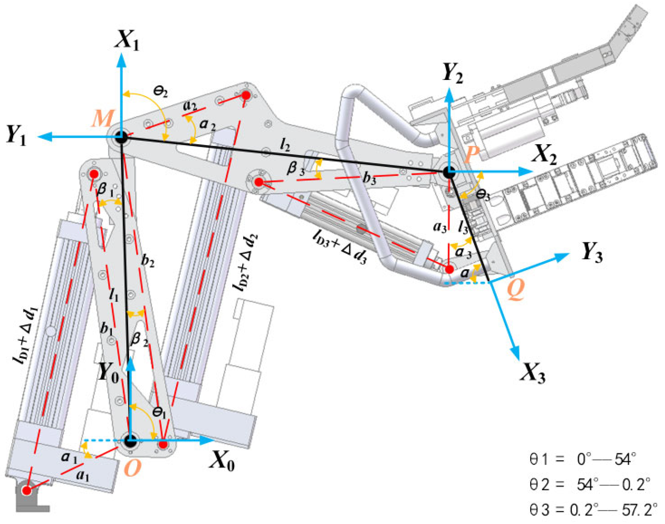
Before trajectory planning for the piggyback transfer robot’s movement, kinematic analysis of the carrying part is imperative to establish the correlation between the chest holder pose and the extension and contraction of the electric cylinders’ push rods.
As shown in
Figure 2, the robot carrying part is simplified to a three-link planar tandem mechanism, and the coordinate system origin of its kinematic model is located at the center point
of the rotary joint between Arm1
and the frame. For the robot motion control, the spatial position of the chest holder
is controlled by its articulation point
P with Arm2
, and the attitude defined by the chest holder angle, Therefore, the coordinates of the point
and the chest holder angle
can be used to describe the chest holder’s pose.
The D-H parameters of the carrying part are given in
Table 1.
According to the D-H method [
22], each joint rotation angle
and the chest holder pose
can be obtained as
The displacements of three electric cylinders can be obtained from the red triangular geometric relationship of
Figure 2 using the cosine theorem:
where
and
are arm 1, arm 2 and chest holder lengths,
and
are joint angles,
and
are electric cylinder displacements, and
and
are the carrying part length parameters as shown in
Table 2.
are the angle parameters of the carrying part, as shown in
Table 3.
2.1.3. Back-Carrying Trajectory Planning for Piggyback Transfer Robot
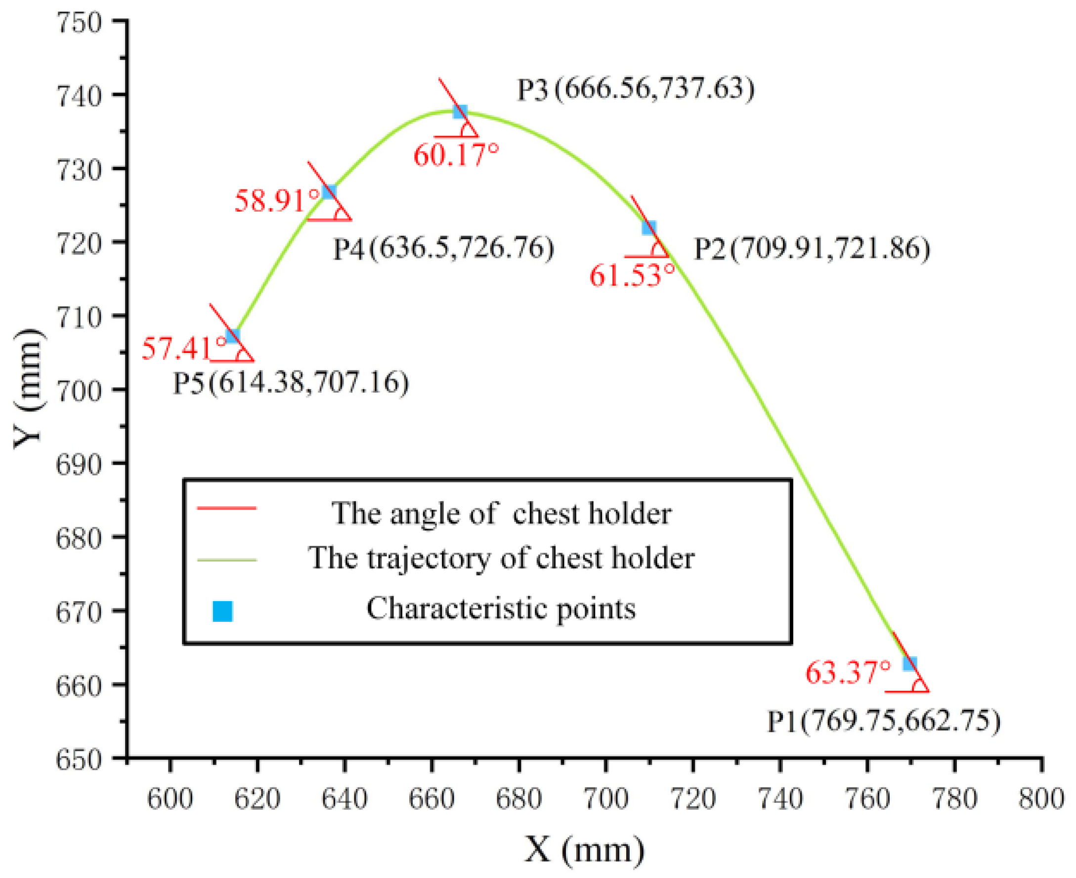
In the context of the piggyback transfer robot, the phase that most significantly affects comfort is not the transfer itself, which involves minimal changes in the care recipient’s posture, but rather the act of lifting the individual from their initial position to the state of being carried by the chest holder—referred to as the back-carrying motion. This motion includes five characteristic trajectory points: the motion start point, the rise midpoint, the motion midpoint, the fall midpoint, and the motion end point. By determining the coordinates at which the subject feels comfortable at these five points, a reasonable and smooth back-carrying trajectory can be generated using the cubic Hermite interpolation method.
Based on multiple preliminary experiments and questionnaire surveys, five comfortable characteristic trajectory points were initially identified based on the majority of participants’ feedback—P1 (769.75, 662.75, 63.4°), P2 (709.91, 721.86, 61.5°), P3 (666.56, 737.63, 60.2°), P4 (636.50, 732.76, 58.9°), and P5 (614.38, 707.16, 57.4°)—where displacements in the X and Y directions are in millimeters, and the rotation angle is in degrees. The basic motion trajectory interpolating the five characteristic trajectory points above is shown in
Figure 3. This trajectory serves as a preset reference for the robot back-carrying process, enabling subsequent adjustments to application-specific trajectories, thus avoiding the blindness of randomly setting trajectory parameters.
The process of adjusting the characteristic trajectory points of the comfortable carrying trajectory for participants with various body types is as follows: First, P1 and P5 are determined, with their coordinates set such that the participant’s hip is just free of external force. Next, the highest point, P3, is identified. Based on multiple experiments, it was observed that the participant’s knee angle at P3 is between 95° and 105°, which serves as a reference for adjusting the chest holder coordinates. P2 is placed between P1 and P3, and P4 between P3 and P5, with the X-coordinates and Y-coordinates of P2 and P4 positioned near the midpoint of their neighboring points. At each of the identified coordinates, the chest holder is rotated, allowing the participant to feel changes in comfort caused by angle variations. The final chest holder angle is determined based on the participant’s subjective feedback.
Using the five characteristic trajectory points described above, the back-carrying process of the piggyback transfer robot can be divided into 5 motion phases, which are shown in
Figure 4: touching, lifting, reaching the top, descending, and reaching the saddle. Prior research has indicated that the robot’s chest holder rotation angle during these phases affects the participants’ comfort more than the horizontal and vertical displacement [
23]. Based on this, this study proposes an active control method based on ELM-GA to dynamically adjust the chest holder’s rotation angle, thereby enhancing the comfort of the care recipients during the carrying process.
2.2. ELM-GA-Based Active Comfort Control Algorithm for Piggyback Transfer Robot
2.2.1. Test and Analysis of sEMG
During the back-carrying process, many muscles of care recipients are activated, particularly those of the upper body, and muscle activation can be assessed using sEMG signals. The sEMG signals are time-varying signals with a voltage range at microvolt level, typically between 50 μV and 100 mV, and most signals are within the frequency range from 10 to 500 Hz [
24].
Given the limitations of the robot-assisted handling position, it was not feasible to place sensors on the pectoral or abdominal muscles, so the focus was on the back muscles. This study focuses on the sEMG signals from the participants’ back muscles, using the TrignoTM Wireless EMG system. This non-invasive method enables reliable acquisition of muscle activation data, with a focus on four key back muscles, as depicted in
Figure 5, which illustrates the muscle distribution and sensor placement.
Time domain features of the sEMG can reflect its signal changes with time increase simply and quickly. Its commonly used indices include integral electromyogram (
iEMG) and root mean square (
RMS) [
25].
The calculation formula of
value is
The calculation formula of
RMS value is
The magnitude of the RMS is determined by the amplitude of the sEMG signal, which can be used to determine the timing and extent of muscle fatigue by comparing RMS at different times. The integrated EMG (iEMG) reflects the magnitude of the discharges of each motor unit and the number of myofibers involved during muscle contraction. The muscle activation test experiment requires obtaining the degree of muscle activation in different postures during carrying, so the RMS value is an appropriate metric to analyze sEMG signal.
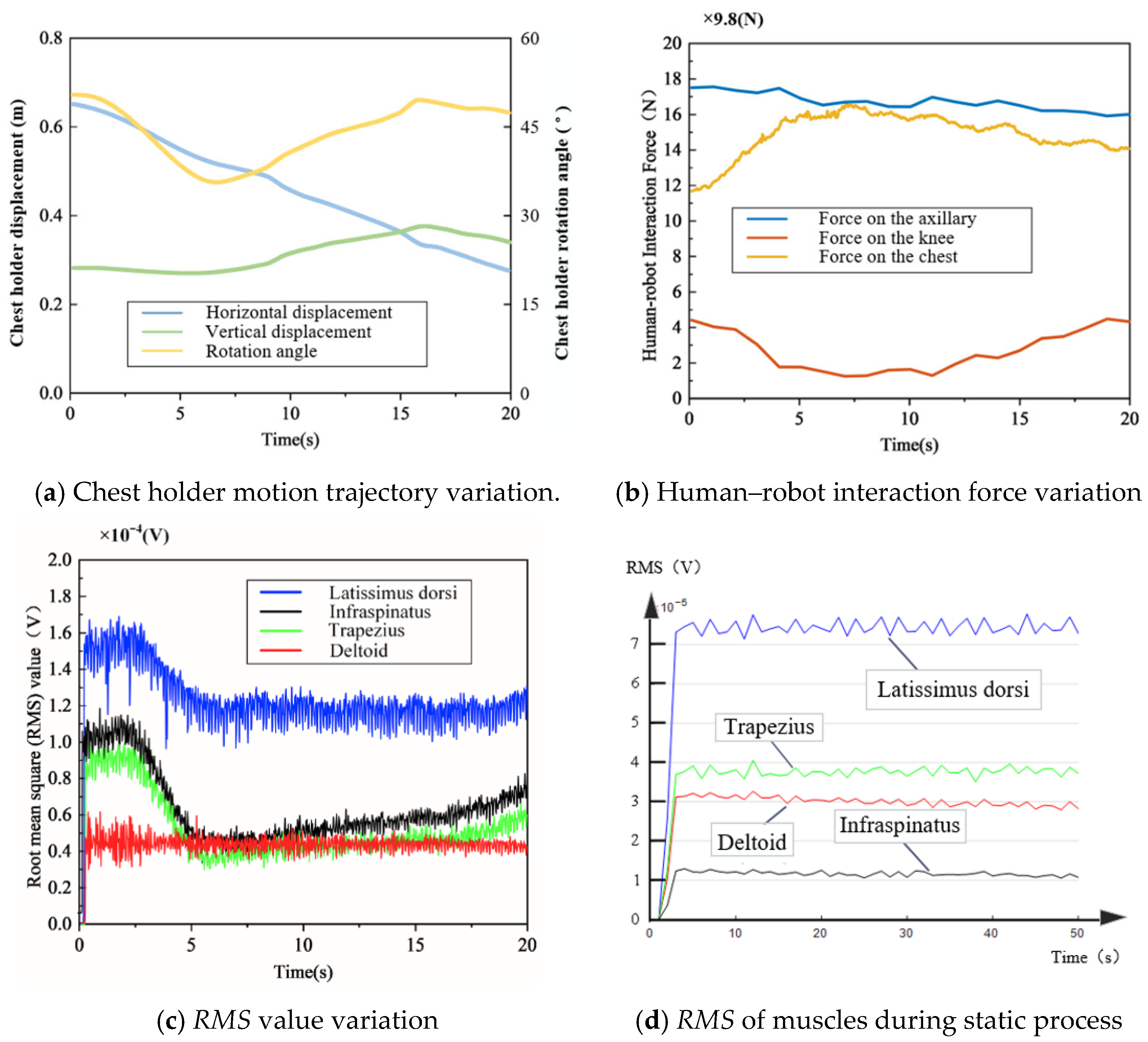
Changes in human–robot interaction forces and muscle activity were recorded throughout the back-carrying process using the test system and sensors described above.
Figure 6 illustrates the trajectory of the chest holder, the human–robot contact force and sEMG signals during the back-carrying process, as well as the
RMS values of muscles during the static phase. The results of the experiment showed that the deltoid muscle did not change significantly throughout the process, indicating low activation and limited involvement. The changes of the latissimus dorsi, infraspinatus muscle and trapezius muscle were the same, and they all changed with the movement of the chest holder. In particular, the
RMS value of the latissimus dorsi muscle was the largest in all postures. Therefore, when analyzing participants’ comfort, emphasis should be placed on latissimus dorsi muscle activation.
Figure 7 shows the changes in chest force contour maps measured using the Tekscan CONFORMat array pressure sensor. The results indicate that during the lifting phase, the contact area between the participant’s chest and the chest holder gradually increases with the primary external load. At the highest point of the robot’s trajectory, the chest is almost fully in contact with the chest holder, and the chest force reaches its peak. As the robot starts to descend, slight adjustments in the chest holder’s position result in a modest reduction in both force and contact area. Once the participant is seated, the robot maintains a fixed posture while moving them forward.
2.2.2. OS-ELM-Based Model Building and Training for Active Control Algorithm
Compared to traditional neural networks, the Extreme Learning Machine (ELM) offers significant advantages in real-time applications, enabling efficient learning with fewer training samples. This makes ELM particularly well-suited for modeling complex, nonlinear relationships, especially in regulating the chest holder’s rotation angle during back-carrying, which affects latissimus dorsi muscle activation and comfort levels. To further enhance adaptability, we employ the Online Sequential Extreme Learning Machine (OS-ELM) [
26], which supports continuous learning and adaptation to new data without retraining from scratch—ideal for dynamic environments like robot-assisted care. Experimental data were collected from a diverse group of participants to train an OS-ELM-based model, with body information for 10 representative participants shown in
Table 4.
During the experimental procedure, we identified the most comfortable characteristic points for each participant based on their feedback and recorded the corresponding latissimus dorsi sEMG signals using the TrignoTM Wireless EMG system at these points. Additionally, participants performed a specific maximum voluntary contraction (MVC) calibration procedure [
27] for the test system to collect sEMG values of the participants’ latissimus dorsi muscle when it is at the maximum activation level.
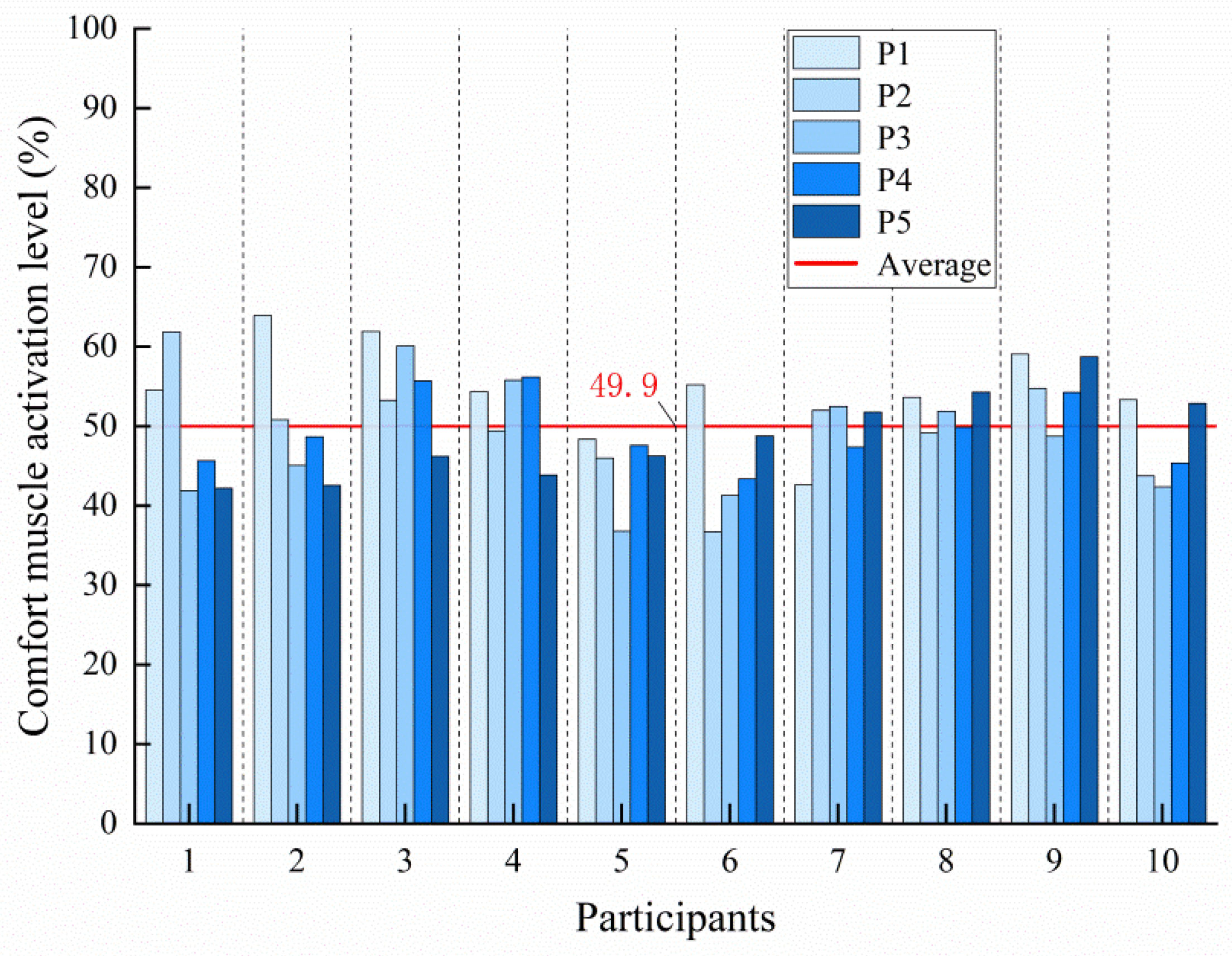
The muscle activation level is represented as a percentage of the
RMS value (calculated from the recorded sEMG signals using Equation (4) relative to the
RMS value obtained during the MVC trial. The
RMS values of latissimus dorsi sEMG during comfort state and maximum activation state in 10 participants are listed in
Table 5.
From these data, we calculated the average activation level of the latissimus dorsi muscle during the comfort state to be 49.90%, as depicted in
Figure 8. While the current manuscript, due to space limitations, presents detailed data from a representative subset of 10 well-characterized participants to illustrate the key trends in muscle activation and comfort trajectories, the 49.9% threshold is computed as the group average across all 30 participants. Thus, although only 10 participants are shown in detail for clarity and conciseness, the 49.9% comfort threshold is statistically robust, grounded in a larger dataset, and accounts for inter-subject variability through proper normalization and group-level analysis.
That is to say, high muscle activation increases participants’ fatigue and low muscle activation means that muscles are not functioning in a stable manner; both scenarios diminish the comfort experienced by the care recipients. Thus, the deviation of the muscle activation from 49.90% during back-carrying can be used as an important indicator to verify care recipients’ comfort.
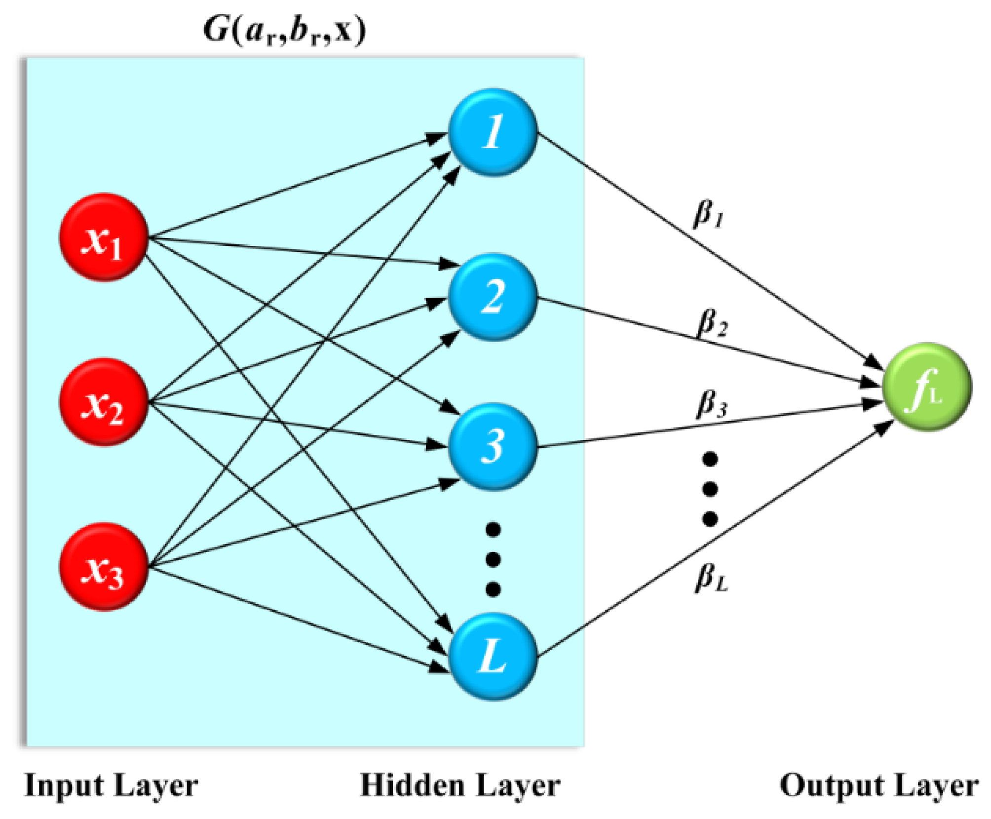
The OS-ELM neural network model maps human–robot interaction forces (chest and axillary forces) and the chest holder angle to muscle activation levels. As illustrated in
Figure 9, the network is structured with 3 input nodes,
L hidden nodes and 1 output node, configured as a single-layer feedforward network (SLFN). Number of hidden layer nodes: Set to 50 based on empirical experience and subsequently fine-tuned through a trial-and-error approach to achieve optimal model performance. Activation function: The Sigmoid function is selected as the activation function for the hidden layer neurons due to its effectiveness in handling nonlinear problems. Training setup: A batch learning strategy is adopted, in which the model is updated once every time a new set of data samples is collected, enabling real-time adjustment of the predictive model.
The output function of the SLFN is mathematically expressed as follows:
As illustrated in Equation (6), the SLFN depicted in
Figure 10 comprises three input nodes:
x1 (axillary force
YF),
x2 (chest force
XF) and
x3 (chest holder angle
).
(muscle activation deviation of the latissimus dorsi muscle
) is used as the output.
In addition,
and
are the learning parameters of the hidden nodes,
is the output weight, and the activation function
denotes the output of the
hidden node with respect to the input
x. Based on this SLFN architecture, the OS-ELM training procedure is summarized in
Figure 10:
The hidden layer output matrix
, along with
and
, is mathematically expressed as follows:
With the obtained above, the SLFN output function represented in Equation (5) can be applied as a pre-trained predictive model for the active control algorithm to improve the robot-assisted carrying comfort.
2.2.3. Active Control Algorithm Optimization for Enhancing Robot Comfort
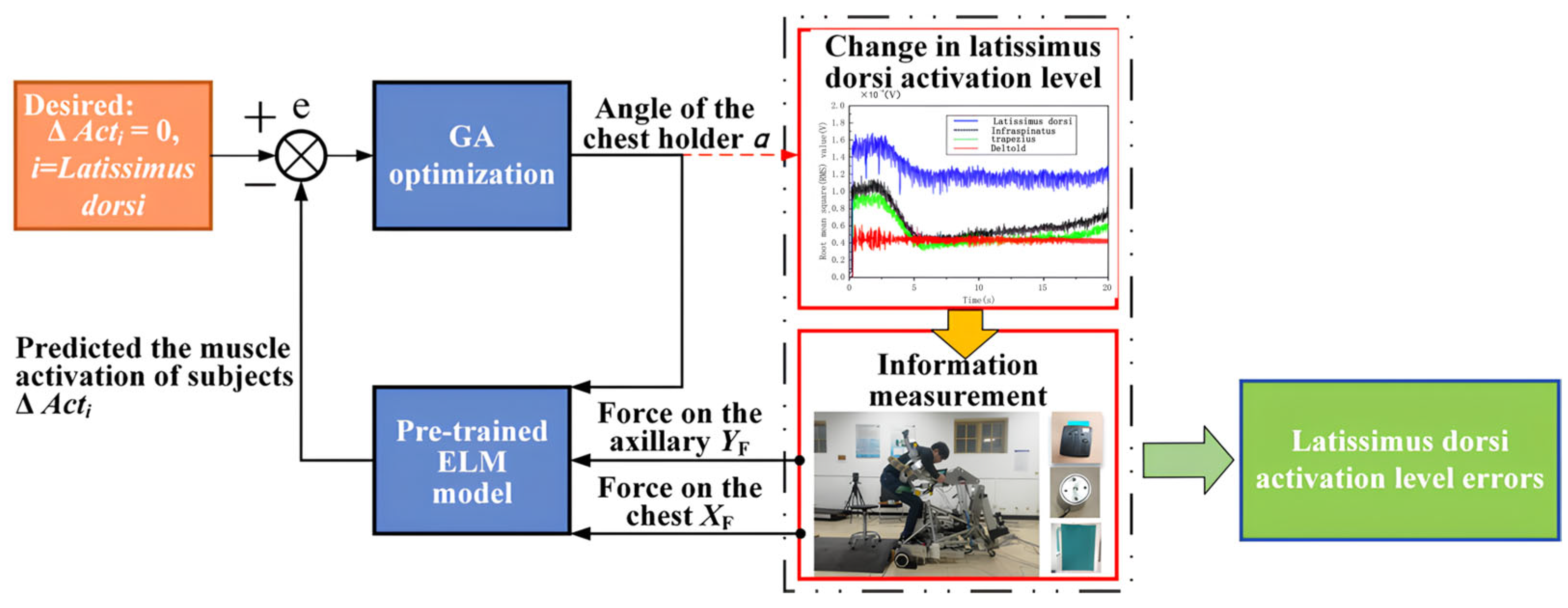
Utilizing a pre-trained OS-ELM predictive model, the proposed algorithm achieves optimization according to the control mechanism illustrated in
Figure 11: During the back-carrying process, the axillary force, the chest force, and the chest holder angle are detected. The first two variables, serving as critical input variables for the active control algorithm, are derived from real-time sensing, while the latter requires dynamic adjustment through an optimization method. The goal is to minimize the discrepancy between the predicted muscle activation levels and the actual comfortable muscle activation.
To optimize these adjustments, we employed the Genetic Algorithm (GA), which employs population search techniques. The GA applies genetic operations such as selection, crossover, and mutation to generate successive populations, gradually evolving toward the optimal solution. The advantages of GA include strong robustness, convergence to a global optimum, and parallel search capabilities [
28], making GA particularly well-suited for optimizing the chest holder rotation angle to enhance care recipients’ comfort.
Population size: Set to 50 to ensure sufficient genetic diversity while maintaining computational efficiency. Mutation rate: Set to 0.01 to introduce new genetic variations and promote population evolution. Crossover rate: Set to 0.7 to ensure a high probability of gene recombination, thereby facilitating exploration of the solution space. Termination criterion: The GA terminates when the best fitness value of the population does not show significant improvement over 20 consecutive generations, or when the maximum number of iterations (e.g., 100 generations) is reached.
Owing to these advantages, GA can be appropriately adopted for the dynamic optimization regulation of the chest holder rotation angle of the piggyback transfer robot, based on the pre-trained predictive model above.
To ensure the effectiveness and practical applicability of the proposed ELM-GA active control strategy, it is essential to explicitly define the constraint range for the chest holder angle and conduct a sensitivity analysis on the comfort threshold to verify the robustness of the model.
Constraints on the Chest Holder Angle: Within the optimization objective function defined in Equation (10), the rotation angle θ of the chest holder must satisfy certain physical and ergonomic limitations. Based on prior experimental studies and ergonomic design principles, the following constraints have been established: The minimum angle is set to θ_min = 15°, ensuring a baseline level of user comfort even under the most confined operational conditions. The maximum angle is set to θ_max = 45°, which serves as an upper bound to prevent excessive adjustment that could lead to increased discomfort or potential safety hazards. This ensures that all solutions generated by the Genetic Algorithm (GA) remain within a physiologically acceptable and mechanically feasible range.
Sensitivity Analysis on the Comfort Threshold: To evaluate the adaptability and robustness of the defined comfort threshold with respect to inter-individual variability, a systematic sensitivity analysis was conducted. The procedure is as follows: Definition of the Comfort Threshold: Based on previous experimental data, participants consistently reported a comfortable state when the average activation level of the latissimus dorsi reached approximately 49.9% of maximum voluntary contraction (MVC). This value was therefore adopted as the initial comfort threshold. Threshold Variation: The threshold was systematically varied by ±5% and ±10%, and the resulting changes in system performance metrics—such as subjective comfort ratings and latissimus dorsi activation levels—were analyzed. Although the comfort threshold is not directly optimized, it serves as a critical reference for dynamically adjusting the chest holder angle during the GA-based optimization process. Consequently, variations in the threshold lead to corresponding changes in the optimal angle and, ultimately, in the perceived comfort outcome.
The results demonstrate that moderate adjustments to the comfort threshold do not significantly degrade the overall system performance. Subjective comfort ratings and muscle activation levels remain stable across the tested range, indicating that the proposed ELM-GA control strategy exhibits strong robustness and adaptability to individual differences. This analysis confirms the reliability of the control framework in real-world applications involving diverse user populations.
The optimization objective of the GA active control algorithm is as follows:
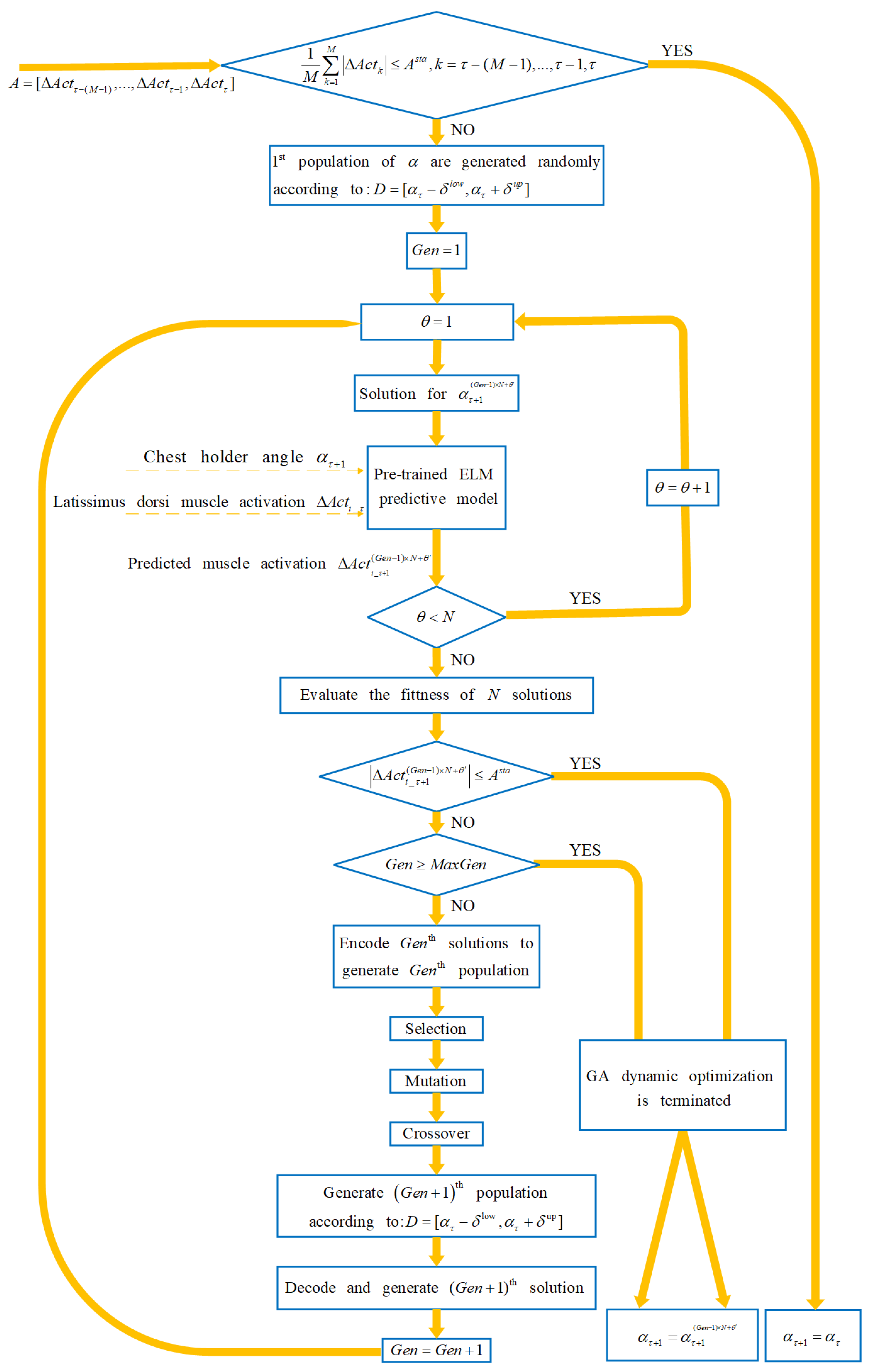
The dynamic optimization and updating process of the chest holder rotation angle
at any moment
based on the GA method is shown in
Figure 12:
To achieve efficient collaboration between OS-ELM prediction and GA-based optimization, a dynamic feedback control loop has been designed as follows:
Update frequency: Every 1 s, the system performs a prediction using the OS-ELM based on current state information, and the predicted output is fed into the GA as part of the initial population for optimization.
Latency: Considering computational resource constraints, there is a 200 ms time delay between the generation of an optimized solution by the GA and its application to the actual control system. This delay is introduced to ensure system stability and response consistency.
This cooperative mechanism not only enhances the accuracy of predicting latissimus dorsi activation levels but also enables the robotic system to adjust the chest plate angle in real time, thereby maximizing user comfort.
2.3. Experimental Procedure
The effectiveness of the active comfort control method in robot-assisted carrying is evaluated using the experimental platform above. To assess the subjective perceptions of participants during the back-carrying process, a standardized questionnaire survey is also implemented (refer to
Table 6 for details).
The experimental procedure is as follows:
In this experiment, 6 participants exhibiting diverse heights and weights, including both males and females, were selected from the overall participant pool. Participant characteristics are delineated in
Table 7. Prior to the experiment, participants were briefed on the procedural steps and necessary precautions. Participants were instructed to abstain from food intake immediately preceding the experiment to mitigate the potential influence of satiety on experimental outcomes.
For each experiment trial, the chest force, axillary force, and sEMG signals were continuously recorded. Initially, considering the negligible impact of horizontal and vertical position changes on human comfort, a preset trajectory was selected by adopting the X and Y coordinates from the motion trajectory obtained in preliminary tests, while the chest holder’s rotation angle was initialized randomly. The robot then carried the participants to the target position based on the preset trajectory according to the traditional carrying strategy (position-based open-loop control). In open-loop control, the controller sends output signals according to pre-set command values without utilizing real-time feedback to adjust its output.
Subsequently, the same participant was transferred to the target location once more, this time employing the proposed ELM-GA active control strategy. The active control trajectory mirrored the horizontal and vertical parameters of the preset trajectory, while the chest holder angle was dynamically optimized in real time.
The chest plate rotation angle was set to a randomly selected value rather than the dynamically optimized angle generated by the Genetic Algorithm (GA). Specifically, at the beginning of each carrying cycle, the system randomly selected a rotation angle from a predefined angular range to serve as the chest plate angle for that cycle. For each participant, in addition to the trials conducted under the conventional control strategy and the ELM-GA active control strategy according to the established protocol, three additional trials were performed under the randomized control condition. After each trial, key metrics including the participant’s subjective comfort rating and the activation level of the latissimus dorsi (measured via sEMG) were recorded and analyzed. This experimental design enables a more comprehensive comparison and further highlights the effectiveness of the intelligent optimization in the proposed control framework.
To facilitate muscle recovery and reduce fatigue, participants were granted appropriate rest intervals.
To minimize the influence of learning effects and other systematic biases on the experimental outcomes, the testing sequence for all participants was randomized. Specifically, the order in which each participant experienced the different control strategies—namely, the conventional control strategy and the proposed ELM-GA active control strategy—was determined using a computer-generated random sequence. This counterbalancing approach was employed to evenly distribute potential order-related effects across conditions.
Considering the importance of muscle recovery and fatigue reduction, a 10 min rest period was scheduled between consecutive experimental trials. During this interval, participants were instructed to sit quietly and relax, and their subjective comfort ratings were recorded. To empirically evaluate whether the 10 min rest duration was sufficient to mitigate fatigue, we continuously monitored the surface electromyography (sEMG) signals of the latissimus dorsi muscle throughout the experiment and analyzed the temporal trends in muscle activation. The results indicated that, after the 10 min rest, the activation levels of the latissimus dorsi in the majority of participants returned to their baseline values, suggesting that this rest period is effective in alleviating muscular fatigue and facilitating functional recovery.
Furthermore, to confirm the efficacy of the rest interval, we compared experimental data obtained under conditions with and without the prescribed rest period. The analysis revealed that participants who adhered to the 10 min rest protocol exhibited more stable sEMG patterns and more consistent subjective comfort ratings in subsequent trials. This finding further substantiates the importance of the 10 min rest interval in maintaining data reliability and overall experimental integrity.
Following each experiment, a 10 min rest period was mandated, after which participants were prompted to document their comfort assessments for the specific carrying instance. This practice ensures that each trial was initiated under consistent conditions, thereby enhancing the reliability and comparability of the experimental data. Each experiment was repeated three times to minimize chance in the experimental data.
The reason we present detailed results from 6 representative participants in this paper is primarily due to space limitations and the need to maintain clarity in illustrating key findings, such as the correlation between sEMG responses, comfort ratings, and motion trajectories and without overwhelming the reader with redundant data. These 6 individuals were carefully selected to reflect a typical range of anthropometric and biomechanical characteristics observed in the broader cohort, and their data exemplify the consistent trends seen across the larger sample.
3. Results and Discussion
3.1. Subjective Ratings
The subjective comfort ratings in the comparison experiments are shown in
Figure 13: the active control strategy is rated higher by all participants, who believe that the ELM-GA-based active control strategy would improve robot comfort by adjusting the chest holder angle.
Paired t-test analysis revealed that participants’ subjective comfort ratings under the ELM-GA active comfort control strategy were significantly higher than those observed with the traditional carrying strategy (*t* (5) = 2.35, *p* < 0.05). This indicates that adjusting the chest plate angle can effectively improve users’ comfort during the transfer process. Specifically, as shown in the figure, the trend of rating changes from Participant 1 to 6 is clearly evident, with the ELM-GA strategy consistently yielding higher scores in most cases. Furthermore, the effect size, measured by Cohen’s *d*, was 0.8, indicating a medium-to-large practical significance of the difference between the two conditions. The 95% confidence interval was estimated to be [0.4, 1.2], further supporting the robustness and reliability of the findings above.
3.2. Activation Level of Latissimus Dorsi Muscle
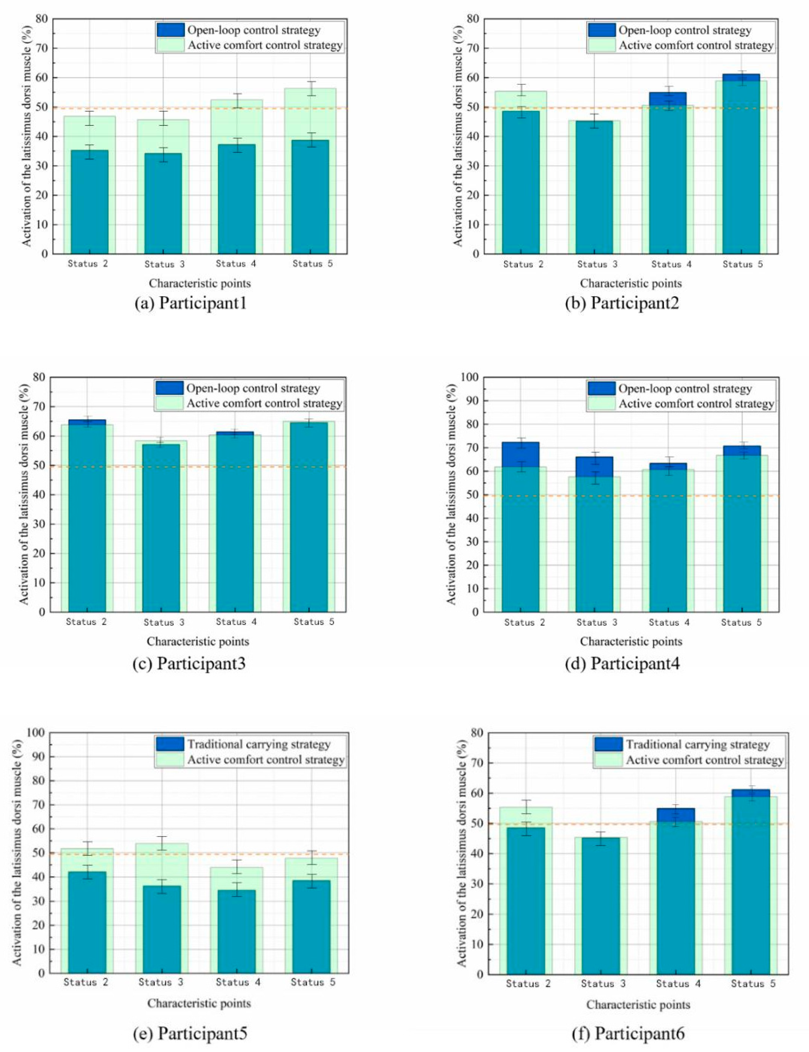
A comparative analysis of the latissimus dorsi muscle activation levels between the traditional and active comfort control strategies is presented in
Figure 14. The results indicate that the muscle activation under the active control strategy aligns more closely with the optimal comfort state activation levels, as previously defined.
A paired t-test was conducted on the activation levels of the latissimus dorsi to evaluate the effectiveness of the ELM-GA active comfort control strategy. The results showed that, after implementing the strategy, participants’ latissimus dorsi activation levels were significantly closer to the optimal activation level associated with maximum comfort (e.g., *t* (5) = 2.47, *p* < 0.05). This indicates that dynamically adjusting the chest plate angle can effectively optimize muscle activity and thereby enhance user comfort. The effect size, as measured by Cohen’s *d*, was 0.9, suggesting a large practical significance of the difference between the two conditions. Furthermore, the 95% confidence interval was estimated to be [0.35, 1.00], which supports the robustness and reliability of the findings.
3.3. Discussion
This study presents an innovative active trajectory control method based on ELM-GA, successfully applied to piggyback transfer robots. Compared to conventional trajectory control approaches, evaluation results demonstrate that this approach significantly stabilizes latissimus dorsi muscle activation and enhances subjective comfort.
By collecting surface electromyography (sEMG) signals from multiple key muscles in the backs of a cohort of participants, it was found that latissimus dorsi activation exhibited the most pronounced variations during robot-assisted transport, with the highest activation values observed across all postures. Consequently, latissimus dorsi activation was identified as a core physiological indicator for assessing human comfort. Further experiments indicated that when participants felt comfortable, the average activation level of the latissimus dorsi was 49.9%, which was adopted as the target reference value in the robot’s active control system.
Furthermore, both axillary force and chest force were closely related to human comfort, with the rotation angle of the robot’s chest holder significantly impacting comfort levels. This study established a neural network model to characterize the nonlinear relationships among axillary force, chest force, and the rotation angle of the chest holder in relation to latissimus dorsi activation. The model enables real-time prediction of latissimus dorsi activation, allowing for adjustments to the rotation angle of the chest holder that minimize the deviation between predicted activation and the target comfort level (49.9% MVC), thereby enhancing the care recipient’s comfort.
Experimental results revealed that after implementing the proposed active control method, the difference in latissimus dorsi activation levels between each subject and their comfortable state decreased, while subjective comfort ratings significantly improved. This confirms the effectiveness of the active control method in enhancing comfort.
However, this study has certain limitations. During the transfer process, the participant’s chest must maintain contact with the robot’s chest holder, which somewhat restricts sEMG signal acquisition. Furthermore, the effects of the infraspinatus and trapezius muscles on comfort warrant further exploration in future research.
5. Study Prospect
To ensure the broad applicability of the proposed control strategy to the intended target user population, our future research will expand the participant pool to include individuals across a wider range of age groups—particularly older adults—various health conditions, and a more diverse BMI spectrum. Furthermore, additional investigation into personalized adaptation mechanisms, which dynamically optimize control parameters based on real-time user feedback, will be conducted to enhance user experience and improve system adaptability. Through these efforts, we aim to more effectively apply this technology to improve the quality of daily life for elderly individuals and those with mobility impairments, thereby ensuring the generalizability and robustness of the model across diverse user populations.
Although the validity of the proposed method and strategy can be verified by using latissimus dorsi muscle activation exclusively, the influence of other muscles on human comfort needs to be further investigated. Moreover, the comfort study in this paper is limited to the carrying process in which the piggyback transfer robot lifts the care recipients from the original position to the robot, and the comfort of the transferring process and the robot path planning in the room will be solved in the subsequent research.

