1. Introduction
One of the major economic and social engines contributing to the prosperity of a nation is the air transportation industry. It encompasses the movement of people and goods by air, fostering global interactions among individuals, nations, and economies. Air travel facilitates commerce, supports business operations, and stimulates tourism, playing a vital role in communication and globalization. According to the International Civil Aviation Organization (ICAO), global air passenger traffic has doubled every 15 years since 1977, with projections estimating up to 8.2 billion annual passenger journeys by 2037 [
1,
2]. This exponential growth is placing significant pressure on the aerospace sector to increase efficiency, reduce environmental impact, and remain cost competitive.
Fuel consumption is one of the most critical factors in aviation economics and sustainability. Despite doubling its energy efficiency since the 1970s, the aviation sector has seen a continuous rise in total energy use, growing at about 2% annually between 1970 and 1987. The demand for aviation fuel increased from 118,000 barrels per day in 1971 to 4.9 million barrels in 2006 [
3]. Today, civil aviation accounts for approximately 2–3% of total fossil fuel use, with over 80% of that used for commercial operations [
4].
One of the most effective strategies to mitigate fuel consumption is through weight reduction. Reducing 1 kg from an aircraft’s structure can save approximately 0.02–0.03 kg of fuel per flight hour, yielding an estimated 3000 to 4000 kg of annual fuel savings per aircraft [
5]. These benefits not only impact operating costs, but also support global efforts toward decarbonization.
To achieve this, aerospace manufacturers are increasingly adopting Additive Manufacturing (AM), also known as 3D printing. AM is a disruptive and rapidly evolving technology that builds parts layer by layer from digital models, allowing for geometric freedom, material efficiency, and reduction of production waste [
6,
7,
8]. Since Hausholder’s 1979 patent on laser powder sintering [
9], AM has evolved from a rapid prototyping tool to a robust platform for fabricating end-use parts. A landmark example is General Electric’s consolidated fuel nozzle tip for the GE9X engine, which reduced part count from 20 to 1 and lowered weight by 25%, while improving durability [
10,
11].
AM encompasses a wide variety of processes, generally classified by material type, deposition technique, and energy source. According to the ISO/ASTM 52,900 [
12] standard, major technologies include: Vat Photopolymerization (e.g., Stereolithography, SLA) [
13], Material Extrusion (e.g., Fused Deposition Modeling, FDM) [
14], and Powder Bed Fusion (e.g., Selective Laser Sintering, SLS) [
15]. For metals, typical Powder Bed Fusion methods include Selective Laser Melting (SLM) [
16] and Electron Beam Melting (EBM) [
17], while Directed Energy Deposition (DED) (e.g., Direct Metal Laser Sintering, DMLS) is also widely used.
Closely linked to the manufacturing advances enabled by AM is Topology Optimization (TO), a computational design methodology that determines the most efficient distribution of material within a defined domain. First formalized by Bendsøe and Kikuchi in the late 1980s [
18], TO allows the creation of structures that achieve maximum stiffness or minimum weight under specified constraints, often producing biomimetic, highly efficient geometries [
19]. These geometries are typically too complex for conventional manufacturing but are ideally suited to AM.
Modern TO algorithms use finite element methods and iterative material distribution schemes. Among the most widely used approaches are Solid Isotropic Material with Penalization (SIMP) [
20], Evolutionary Structural Optimization (ESO) [
21], and Bi-directional Evolutionary Structural Optimization (BESO) [
22]. These techniques allow designers to minimize material use without compromising mechanical integrity.
The synergistic integration of TO and AM opens new possibilities for the development of lightweight, high-performance components. While TO reduces unnecessary material, AM enables its realization with minimal geometric constraints. This convergence aligns with sustainability goals by reducing CO
2 emissions, optimizing raw material use, and decreasing energy demand during production [
23,
24].
In this study, a combined TO–AM methodology is proposed for the redesign of a supersonic turbofan air intake—a structurally demanding component in aerospace propulsion systems. While the methodology is tailored to a specific case study, its principles can be extended to a broader range of problems.
Three material classes—aluminum alloy 6061, titanium alloy Ti6Al4V, and polyetheretherketone (PEEK)—are assessed for mechanical and manufacturing feasibility. This work aims to validate TO–AM workflows in producing lightweight structural components suitable for the rigorous environment of supersonic flight and to devise a manufacturing process retrofit that enables their production.
Most conventional methodologies that combine TO and AM begin with the selection of a specific material [
25], whose mechanical properties are used to define the optimization parameters (
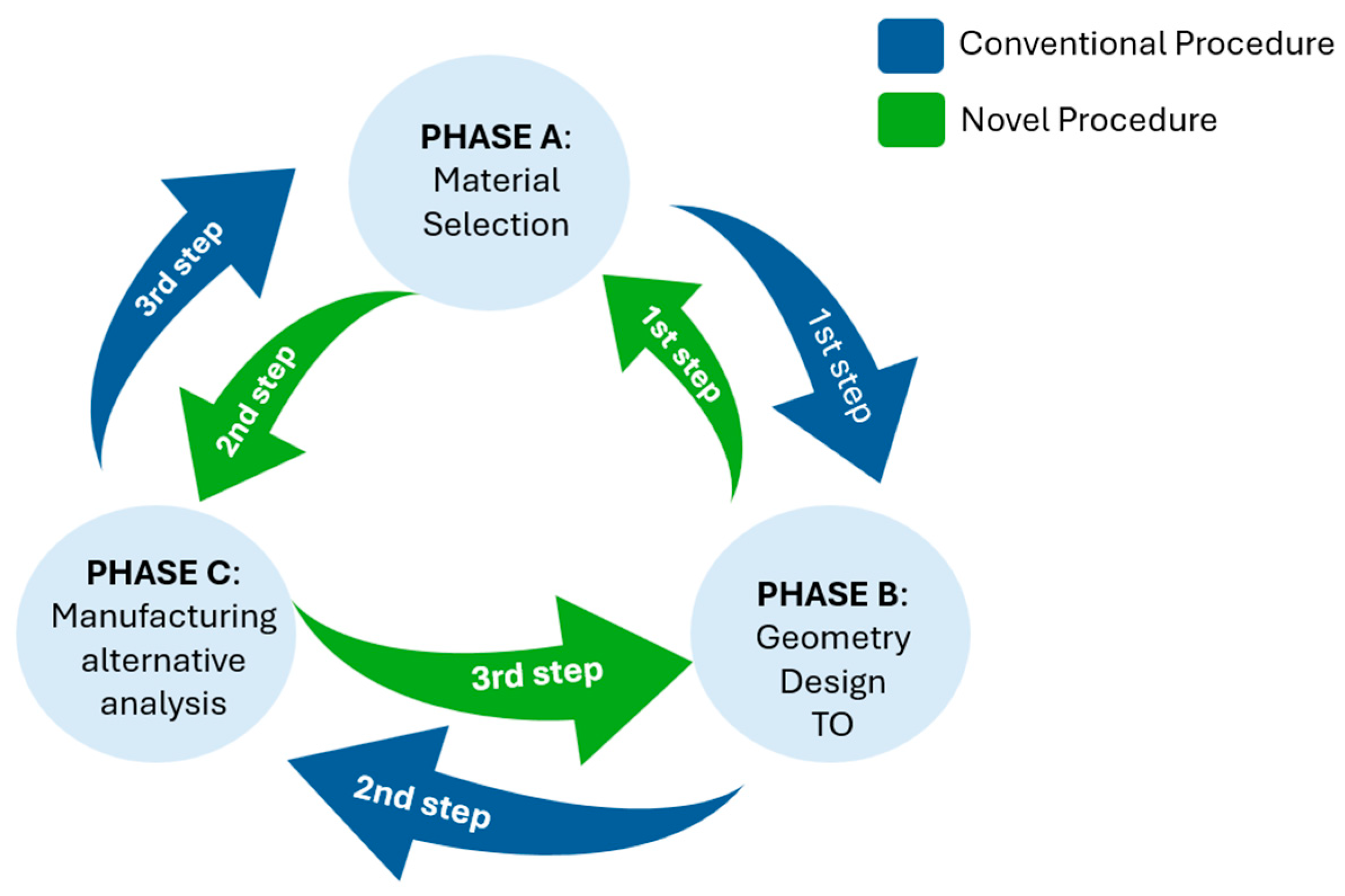
Figure 1, blue arrows). This “material-first” approach typically leads to solutions that are geometrically optimal for the selected material but may not exploit the full potential for weight reduction or structural efficiency when considering alternative materials.
In contrast, the methodology proposed in this work adopts a “design-first, material-second” strategy (
Figure 1, green arrows). The process begins with the use of artificially stiff virtual material that enables the generation of an optimized geometry focused solely on structural and functional requirements—such as stiffness, boundary conditions, and aerodynamic performance. By decoupling the material constraint from the early stages of the design, this method allows the maximization of topological efficiency.
Once the geometry is defined, a subsequent material screening phase evaluates the feasibility of manufacturing the component using different real-world materials (e.g., Ti6Al4V, Al6061, or PEEK). The selection is based on each candidate’s ability to meet structural strength and manufacturability constraints.
This methodological inversion allows a broader and more flexible exploration of viable material alternatives and makes it particularly well-suited for retrofitting aerospace components, where preserving the external geometry is critical, but reducing weight is equally essential. This modified workflow constitutes one of the key novelties of the present work and directly addresses limitations observed in the traditional TO–AM design pipeline.
2. Methodology
In this study, an original design methodology that combines TO and AM simulation is proposed for the redesign of a real-world aerospace component: the air intake of a turbofan engine. This component was chosen for its critical role in engine efficiency and its exposure to significant aerodynamic and mechanical stresses. The design process evaluates three fundamentally different materials to highlight the flexibility of the method across metallic and polymeric substrates: two metallic alloys, the Aluminum alloy 6061 and the Titanium alloy Ti6Al4V, as well as, in contrast, a high-performance polymer, in this last case, the Polyetherketone (PEEK).
The study includes structural simulations and manufacturability assessments, focusing particularly on the feasibility and performance of AM for producing the optimized geometry. By demonstrating the viability of this integrated approach, the work contributes to the development of next-generation lightweight aerospace components that meet strict mechanical and production requirements while enhancing ecological and economic performance.
The overall workflow consists of five sequential stages, as illustrated in
Figure 2. These include: (A) Functional study of aerodynamic and mechanical operating conditions characterization, (B) dimensional design and load analysis, (C) topology optimization using the SIMP algorithm, (D) material selection and mechanical evaluation, and (E) manufacturability assessment using AM processes.
2.1. Stage A: Functional Study, Mechanical Requirements, and Dimensional Analysis
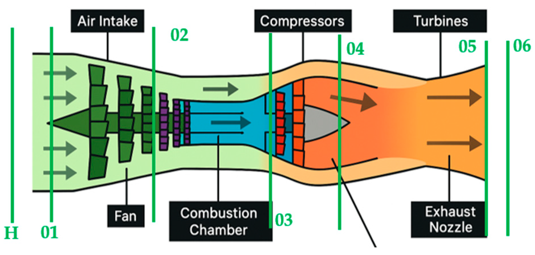
The main function of the turbofan air intake is to ensure controlled and efficient airflow delivery to the engine. In a typical turbofan, air enters through the intake, where it is conditioned before being accelerated by the fan. Part of this air bypasses the engine core (providing additional thrust), while the rest enters the compressor, where pressure and temperature are increased before reaching the combustion chamber. There, it is mixed with fuel and ignited. The resulting high-energy gases drive the turbine, which powers the fan and compressor, before exiting through the nozzle to generate thrust. This simplified process is represented in
Figure 3.
Therefore, the intake plays a key role in initiating the propulsion cycle by adapting external atmospheric air to the optimal thermodynamic conditions for combustion and mechanical efficiency. Hence, the air intake must reduce the incoming flow speed from cruise conditions (Mach ≈ 0.85) to an optimal value of around Mach ≈ 0.45 at the compressor entrance [
26].
To achieve this, the air intake must continuously adapt to varying flight conditions, including changes in ambient temperature, pressure, and speed. This is accomplished through a set of mechanical-hydraulic actuators located symmetrically along the inner walls of the intake. These devices allow the effective cross-sectional area to vary in real time, regulating mass flow and suppressing potential pressure surges.
In supersonic flight conditions (Mach > 1), this process is particularly demanding due to the formation of shock waves, characterized by a steep pressure front propagating faster than the local speed of sound—producing extreme pressure and temperature. These waves—originating from the transition from exterior supersonic to interior subsonic flow—can cause severe instabilities and turbulence if they are not managed properly before the airflow reaches the compressor [
27], potentially compromising engine performance.
To mitigate this, a conical spike or pitot-type centerbody is integrated into the intake front. This geometry intentionally triggers shock waves upstream of the intake mouth, ensuring that flow deceleration and associated pressure changes occur away from the engine core.
The dimensional design of the air intake was established based on nominal cruise conditions—an altitude of 11,500 m and a velocity of 255 m/s—which determine the reference thermodynamic state for the incoming airflow. However, in addition to purely aerodynamic sizing, the design process also accounted for critical supersonic phenomena, such as shock wave formation, pressure gradients, and flow-induced instabilities, which can significantly influence the mechanical performance and structural integrity of the component. As such, the intake geometry was not only tailored to match ideal or cruise flow rates, but also to resist the dynamic loads and pressure surges generated under real operating conditions. In addition to this, thermodynamic parameters, including ambient pressure and temperature, were derived using the International Standard Atmosphere (ISA) model. The initial parameters are presented in
Table 1.
Using these conditions, the required lift force (
D) and intake area were calculated based on the aircraft’s maximum takeoff weight (normally 333,400 kg). The required lift force is expressed as Equation (1) [
28]:
where
CD is the drag coefficient, which, based on several studies, has been shown—particularly for streamlined bodies—to be a function of the induced drag coefficient (
CL) caused by wingtip vortices. This relationship allows the following formulation shown in Equation (2) [
29]:
To select the appropriate airfoil profile, and thereby determine the value of
CL, we refer to the five-digit classifications provided by the National Advisory Committee for Aeronautics (NACA), using a NACA 43012 profile [
30].
To determine the design frontal area of the turbofan intake, it is necessary to solve and rearrange Equation (3) [
31]. This requires calculating the choked (maximum) mass flow rates passing through the intake under design conditions.
To get to the data needed, isentropic and isoenthalpic flow assumptions were applied to estimate mass flow and frontal intake based on total intake conditions. In addition, different hypotheses shown in
Table 2,
Table 3 and
Table 4 were also applied, based on different reports.
2.2. Stage B: Mechanical Load Calculations
Once the intake conditions were defined, mechanical loads were analyzed.
Table 5 presents the pressure loads due to various sources, including velocity deceleration, static pressure differences, centrifugal effects, additive flow redistribution [
31], and shock-induced overpressure.
Table 5.
Mechanical stresses acting on the turbofan air intake.
Table 5.
Mechanical stresses acting on the turbofan air intake.
| Type of Force | Cause | Value | Equation |
|---|
| Speed difference (kPa) | Air deceleration from the air intake entrance to the engine front face | 11.3 | | (4) |
| Static (kPa) | Pressure difference between duct interior and exterior | 52.5 | | (5) |
| Centrifugal (kPa) | Air movement due to engine rotation | 107.1 | | (6) |
| Additive resistance (kPa) | Constant mass flow between two different areas | 0.35 | | (7) |
| Shock wave (kPa) | Shock wave overpressure | 87.0 | | (8) |
| Bird strike test (kN) | High-speed collision of a bird-like object | 650.3 | | (9) |
Based on the aforementioned assumptions, the results obtained, the identified mechanical loads, and the assumed isoenthalpic and isentropic behavior of the flow, it is possible to estimate the internal cross-sectional area of the air intake. It must be emphasized that the design must incorporate a spike to minimize the formation of shock waves, as well as four hydro-mechanical actuators that enable limited regulation of the air intake area to adapt to varying flight conditions. These results will be presented in
Section 3.
Summing up, the air intake considered in this study is designed to operate under supersonic conditions, where both aerodynamic efficiency and mechanical performance are essential. To guide the topology optimization and subsequent material evaluation, a set of structural, functional, and manufacturing requirements was established.
First, the external aerodynamic geometry was preserved throughout the optimization process, as it defines the airflow path and must remain unaltered to ensure proper integration with the engine and surrounding components. This outer surface was therefore defined as a non-design space.
Secondly, the optimal cruise condition for internal flow was established at Mach 0.45, representing the target operational speed for which the internal flow, pressure distribution, and the rest of the operational conditions were calculated. These conditions were used to derive realistic mechanical loads for the simulations, ensuring that the design remains stable and functional under representative aerodynamic conditions.
Structurally, the intake was required to exhibit high stiffness in order to minimize deformation and maintain the geometric fidelity of the airflow channel. In parallel, mechanical strength was ensured by requiring that all stresses remain well below the material yield limit under the applied loads.
Another key objective accomplished is mass reduction, aligned with aerospace design priorities. The optimization aimed to remove as much internal material as possible without compromising mechanical performance, contributing to overall system efficiency.
These multidisciplinary requirements were embedded into the design process to ensure that the final component is not only structurally sound and lightweight, but also compatible with the functional, aerodynamic, and manufacturing demands of a real-world aerospace application.
2.3. Stage C: Topology Optimization
As previously mentioned, TO aims to reduce material usage in order to design lighter and more cost-effective components that still possess sufficient mechanical strength to withstand the loading conditions to which they will be subjected. This ultimately reduces both manufacturing and operational costs.
This methodology allows the transformation of an initial geometry through continuous, bijective, and continuously invertible mappings—i.e., homeomorphisms—which means that geometry can be altered through any transformation that does not involve breaking or separating parts that were connected, nor joining parts that were initially separated.
TO is particularly valuable during the design phase, where it typically results in highly complex geometries that, historically, could not be produced using conventional subtractive manufacturing methods. This limitation explains why topology optimization did not experience significant development until recent years.
However, recently, the number of studies and publications in this field has increased in parallel with the rise of AM technologies [
32,
33].
As a result, several optimization techniques have emerged, all of which are based on computational calculations using finite element methods (FEM). These techniques start from an initial morphology and perform iterative calculations (depending on the selected approach) to obtain the final desired geometry. One major drawback of these methods is their high computational cost, as they involve a large number of parameters for each finite element. Thus, it becomes essential to find a balance between computational cost and the accuracy of the desired result.
Nevertheless, the results obtained are sometimes not sufficiently sharp or well-defined, regardless of the computational load, and may require mesh refinement in specific regions.
Throughout the scientific literature, several TO techniques can be found, among which the most prominent are Solid Isotropic Material with Penalization (SIMP), Evolutionary Structural Optimization (ESO) [
21], and Cartesian grid Finite Element Method (cgFEM) [
34]. Among the available TO methods, the SIMP approach was selected for this study due to its strong balance between performance and implementation feasibility. As described by Rozvany et al. [
35], SIMP offers a mathematically efficient and stable formulation that is well-suited for structural compliance problems, particularly when the objective is stiffness maximization under prescribed loads.
In addition, the review by El Khadiri et al. [
36] highlights the widespread use of SIMP in AM contexts, citing their effectiveness in producing optimized geometries compatible with real-world manufacturing constraints. This makes SIMP highly appropriate for components such as the air intake studied here, where mass reduction, structural rigidity, and manufacturability must be jointly addressed.
Moreover, the SIMP method is natively integrated into Autodesk Fusion 360 v.20602.1.25®, the platform used in this study, enabling seamless coupling between optimization, CAD modelling, and preparation for additive manufacturing. Compared to methods such as ESO or level set formulations, SIMP also facilitates faster convergence and better interpretability of intermediate density regions when suitable filtering is applied.
The SIMP method, introduced by M.P. Bendsøe in 1989 [
20], is a local TO strategy based on maximizing stiffness under a volume constraint. It achieves optimal material distribution within a predefined domain by varying the relative material density (
pi) between 0 and 1 across discretized finite elements. The relationship between material properties and design variables is established via a penalized power-law expression:
where
EH is the homogenized Young’s modulus,
E0 is the base material modulus, and
P is the penalization factor. This penalization promotes a binary design (material or void), leading to physically meaningful structures.
The SIMP approach defines an objective function based on compliance minimization (the inverse of stiffness), thereby maximizing structural rigidity. The stiffness matrix for each element is computed as:
where
ke is the elemental stiffness matrix and
Ee is the penalized modulus. The global stiffness system is assembled as:
with
f being the external force vector and
u the nodal displacement vector. The optimization problem is formulated as:
where
C(
x) is the compliance and
G(
x) enforces volume constraints. Optimization proceeds using regularized fixed-point methods, updating design variables iteratively.
In conclusion, SIMP offers a mathematically rigorous yet heuristically guided framework, enabling continuous improvement of structural designs as computational capabilities evolve, and is implemented in Autodesk Fusion 360
® [
37], which has been selected as the design program used to run the simulations in this work.
This method is compared in
Table 6 with the other ones mentioned above.
2.4. Stage D: Material Selection and Evaluation
To determine the most suitable materials for the application, the Ansys Granta Material Selector v.2025
® software [
38] was used to generate an Ashby diagram [
39], allowing for a visual comparison of the best candidates. The initial material screening was conducted based on tensile strength and density, which are widely used as first-level indicators for evaluating stiffness-to-weight efficiency. This approach aligns with the design objective of maintaining structural performance while minimizing component mass.
While other material properties, such as fatigue life, thermal resistance, and friction coefficient, are highly relevant for long-term performance and functional behavior, their analysis falls beyond the scope of the current methodology-focused study. These parameters are significantly influenced by manufacturing conditions (e.g., build orientation, surface finish).
The current selection strategy thus serves as a preliminary material down-selection tool, enabling compatibility assessment between candidate alloys and the topology-optimized geometry.
As shown in
Figure 4, the most promising candidates are titanium alloys such as Ti6Al4V, aluminum alloys like Al 6061, and magnesium alloys. However, magnesium is excluded due to its relatively poor corrosion resistance and flammability, particularly in powder form, which is critical for additive manufacturing.
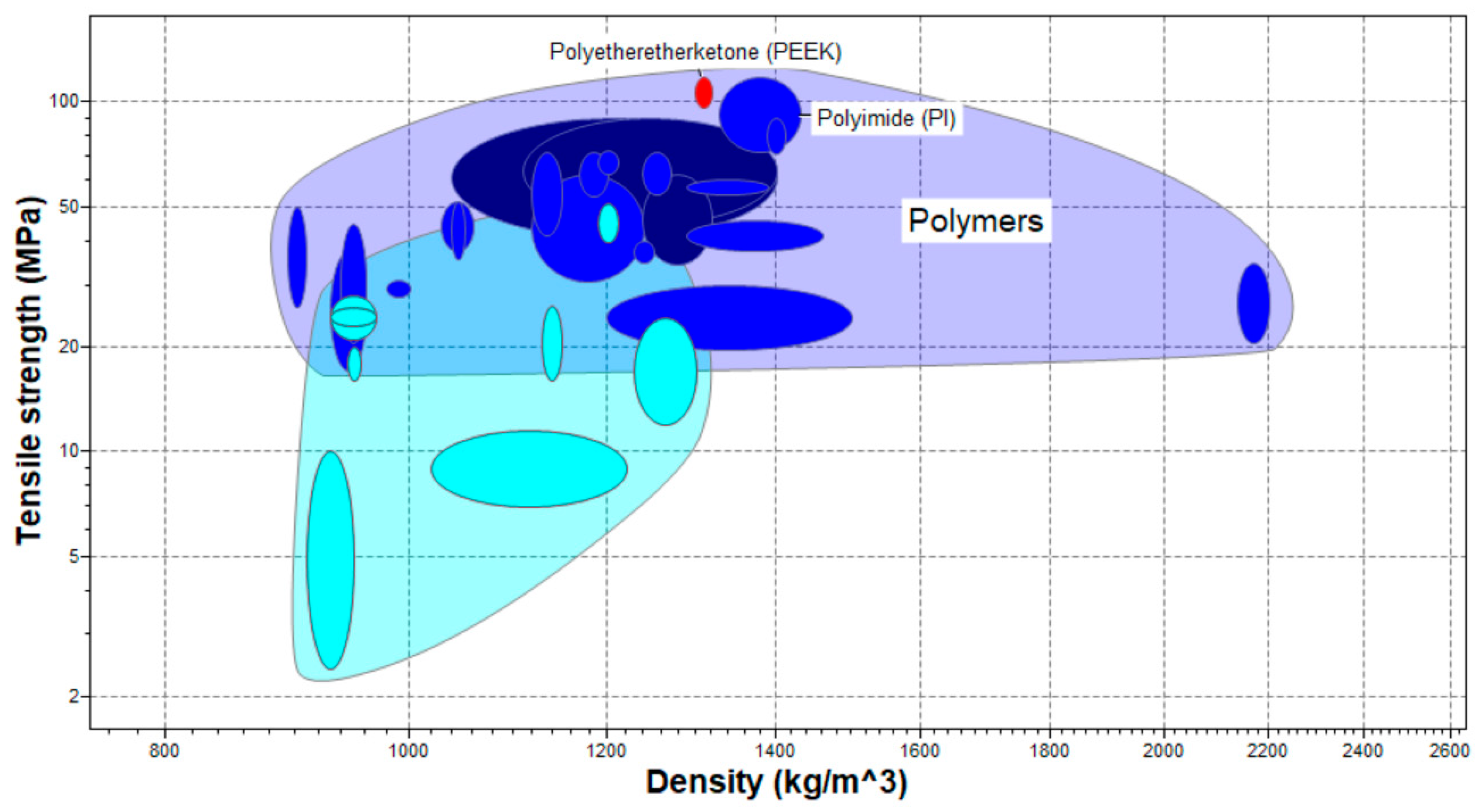
Among high-performance polymers (see
Figure 5), PEEK and Polyimide (PI) stand out. Although they exhibit lower tensile strength compared to the aforementioned metal alloys, they offer the advantage of significantly lower density. For this reason, the performance of the optimized component manufactured in PEEK will also be analyzed.
3. Results
First of all, the thermodynamic results are shown in
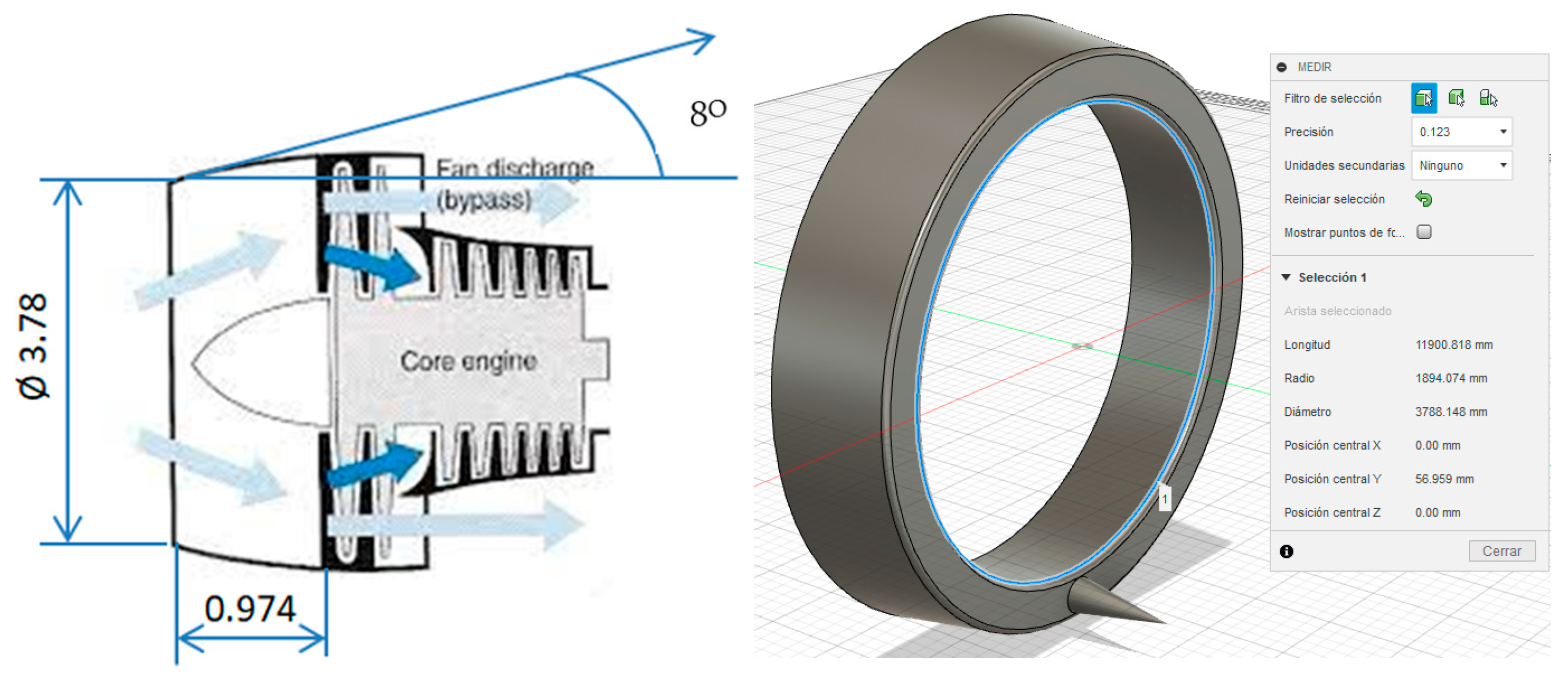
Table 7. Based on all the previously mentioned results and assumptions, the frontal area is calculated according to Equation (3), yielding a final diameter of 3.78 m.
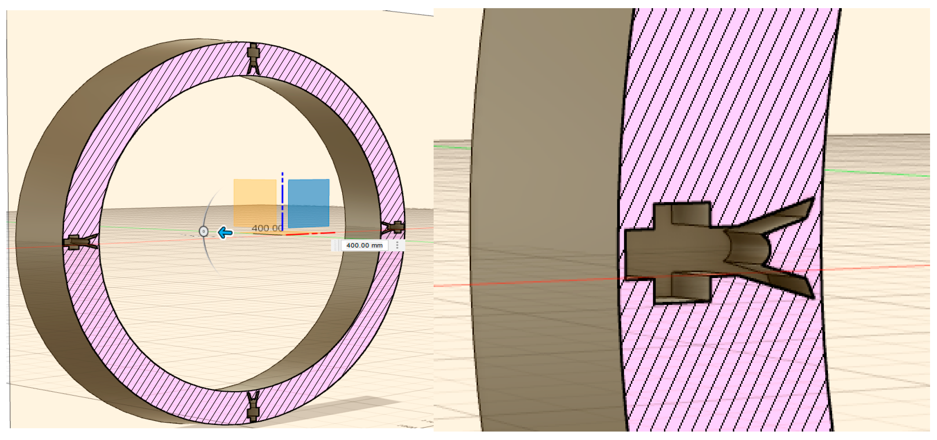
Assuming laminar flow conditions (Reynolds = 2300), an intake width of 0.974 m is obtained, resulting in the design shown in
Figure 6, with some details as mentioned in previous sections and shown in
Figure 7.
Once the dimensional design is clarified, it is proven that under the given calculated loads, which are represented in
Figure 8, where the pressures are uniformly distributed—visualized as blue arrows, while the point loads are indicated by green arrows—the component shows virtually no deformation, indicating that it is likely over-dimensioned. Therefore, it undergoes a regenerative design process based on the SIMP methodology implemented in Autodesk Fusion 360
® [
37], achieving a 71% weight reduction by removing material from the inner volume, while preserving the critical features that must remain unaltered, as is shown in
Figure 8. For this simulation, the finite element mesh used for the static structural analysis was generated in Autodesk Fusion 360
® using parabolic tetrahedral elements. A mesh sensitivity study was performed to evaluate the influence of mesh density on the accuracy of the results and the associated computational cost. Based on the model geometry and the results of this study, an optimal element size equivalent to 1% of the model’s characteristic length was selected, ensuring fine discretization in critical regions without incurring excessive computational overhead.
Curvature-based refinement was enabled with a maximum curvature angle of 60°, allowing the mesh to adapt to geometrically complex areas. The minimum element size was set to 20% of the average size to avoid excessively small elements, and mesh scaling per part was activated to improve local mesh distribution. Additionally, the maximum adjacent element size ratio and aspect ratio were restricted to their minimum allowable values to enhance mesh quality and reduce numerical errors.
This mesh configuration provided a consistent and sufficiently refined discretization that ensured accurate resolution of the mechanical response while maintaining an acceptable computational cost.
The weight reduction reported in this study corresponds to the outcome of the topology optimization process applied to the internal volume of the air intake. The outer aerodynamic shell was retained throughout the process as a non-design space due to strict functional constraints, such as flow control and interface compatibility.
The internal solid volume was defined as the design domain, and the objective function was set to minimize the internal mass while maintaining structural integrity. The applied load conditions correspond to an operating flow of Mach 0.45, which defines the critical aerodynamic pressures acting on the component.
To ensure adequate rigidity, displacement constraints were imposed on key interfaces and mounting regions. No target volume fraction or mass reduction was enforced; instead, the final result emerged from the solver as the most efficient material distribution that fulfilled all imposed constraints.
After optimization, the final mass of the part—including the outer shell and the optimized internal structure—represented approximately 29% of the initial fully solid model, resulting in a 71% reduction in material usage while maintaining stiffness and mechanical performance.
The optimized geometry is subjected to numerical simulation to evaluate its structural performance and durability for each of the selected materials.
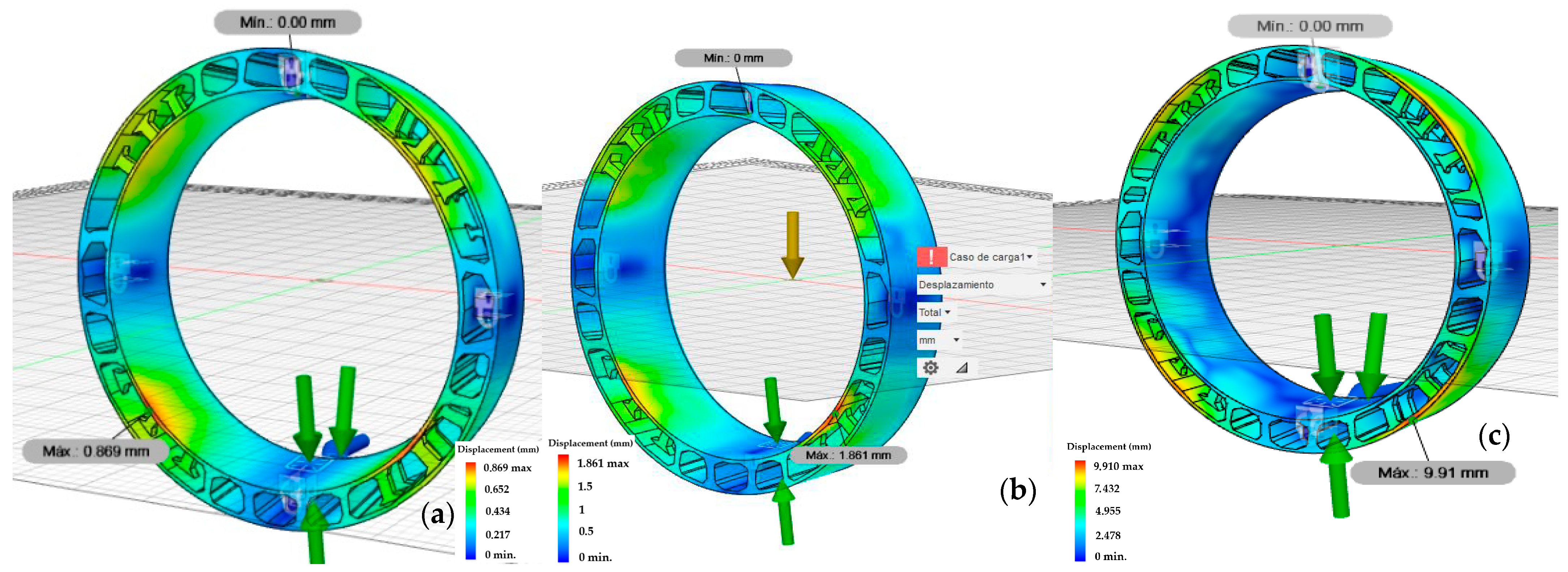
Figure 9 and
Figure 10 illustrate the resulting displacements under the load conditions previously described, where it is demonstrated that while the deformation shape remains consistent across materials, the displacement magnitude varies.
Given the design-first methodology adopted in this work, the geometry of the component remains constant across simulations. Therefore, while different materials (Ti6Al4V, Al6061, and PEEK) result in varying displacement magnitudes due to their distinct mechanical stiffness, the location of the maximum displacement remains unchanged. This is because the deformation pattern is primarily governed by optimized geometry and boundary conditions.
In all cases, the highest deformation occurs in the upper rear region of the component, where the structure presents lower stiffness. The applied loads are modeled as distributed pressures across the internal and external surfaces, rather than as point forces, which explains why the maximum displacement does not coincide with the location of the bird impact load, which acts as a localized force on the front protrusion.
Ti6Al4V exhibits the lowest displacement (0.869 mm), whereas PEEK shows the highest (9.91 mm or 1% of the total length), thus rendering it an inadequate material for the proposed application.
However, PEEK has proven to be a highly efficient material for the manufacturing of complex components intended for energy and vibration absorption, as well as for applications requiring chemical or thermal resistance. Therefore, although it was not suitable for this specific application, it can be proposed for various aeronautical parts such as battery connectors or external light housing, while its use in auxetic structures is being explored to enhance their physical properties [
40,
41].
Among the remaining material candidates (Al 6061 and Ti6Al4V), it is essential to assess the impact of the manufacturing process using Selective Laser Melting (SLM) technology. Even though multiple AM technologies are available, SLM was selected for detailed analysis in this study due to its high dimensional accuracy, material density, and mechanical integrity, which make it particularly suitable for structural aerospace components [
42,
43,
44].
Technologies such as Electron Beam Melting (EBM) or Binder Jetting were considered in the early stages of the design process but were ruled out for the scope of this study due to either lower surface resolution [
45], limited material compatibility, or reduced structural performance. In contrast, SLM supports alloys like Ti6Al4V and Al 6061, which were among the candidates for topology-optimized geometry and are well-established in aerospace AM applications.
4. Stage E: Manufacturability Assessment
To this end, Autodesk Netfabb Premium v.2025
® [
46] is utilized to simulate the SLM process on a generic dual-laser system with build dimensions large enough to accommodate the entire optimized part in a single operation.
Although simulated as monolithic, the actual fabrication of the full-scale component in one piece is not feasible with most current SLM systems due to limited build volumes. Therefore, in a real application, the design would likely need to be divided into smaller subcomponents, which could be joined via welding or mechanical assembly.
Recent studies have shown that laser welding of Ti6Al4V parts manufactured by SLM does not significantly degrade mechanical properties. Rautio et al. [
47] demonstrated joint efficiencies close to 100% in terms of tensile strength, while [
48] highlighted the effectiveness of post-processing in enhancing weld performance. Although no explicit simulation of the welds was conducted here, these findings support the feasibility of the proposed manufacturing strategy.
The geometry includes multiple internal overhangs, requiring a precise and optimal printing process. A proper build orientation is essential to minimize unsupported features and ensure accessible support removal. Post-processing steps would include heat treatment, surface finishing, and potential machining of interfaces or aerodynamic-critical surfaces.
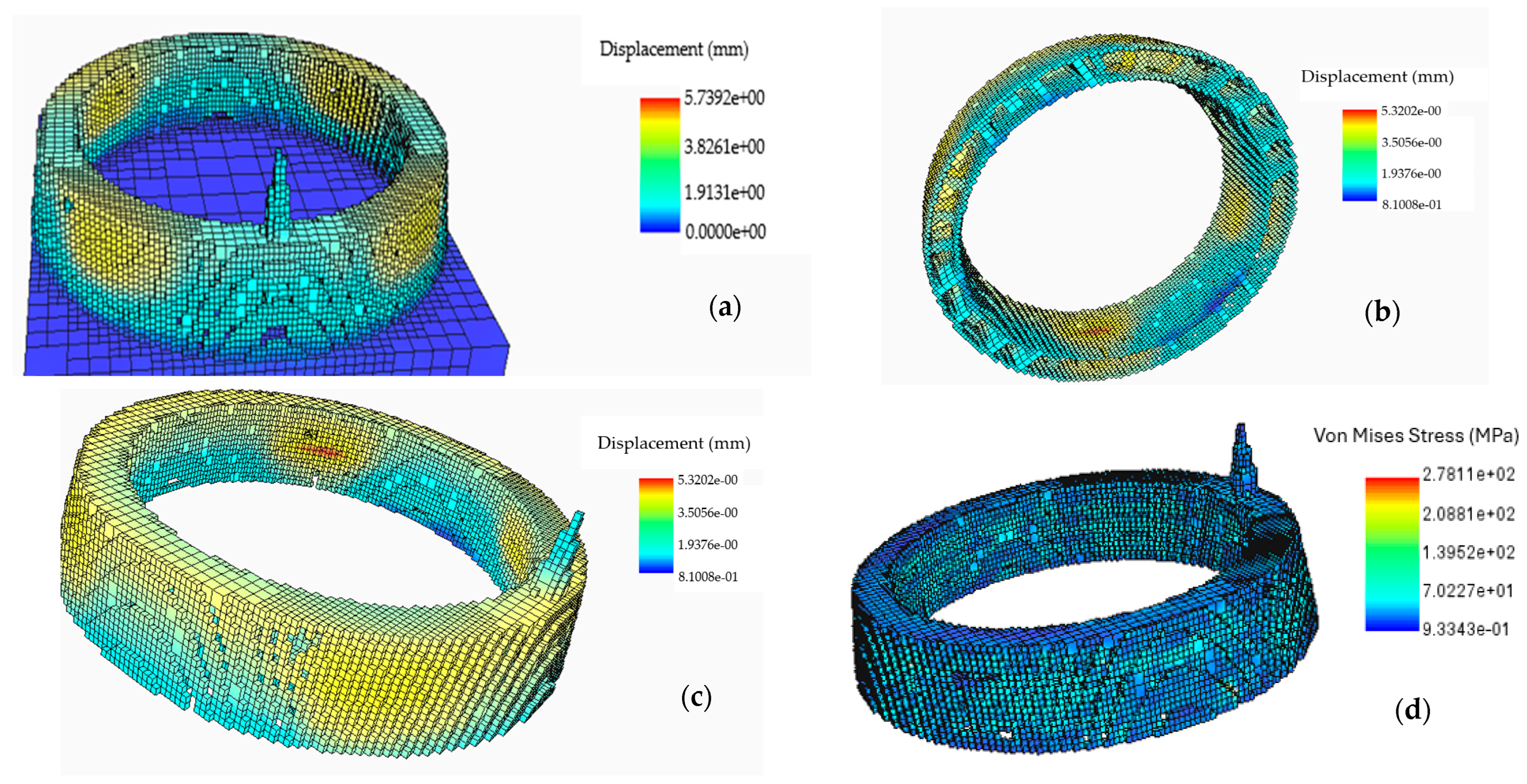
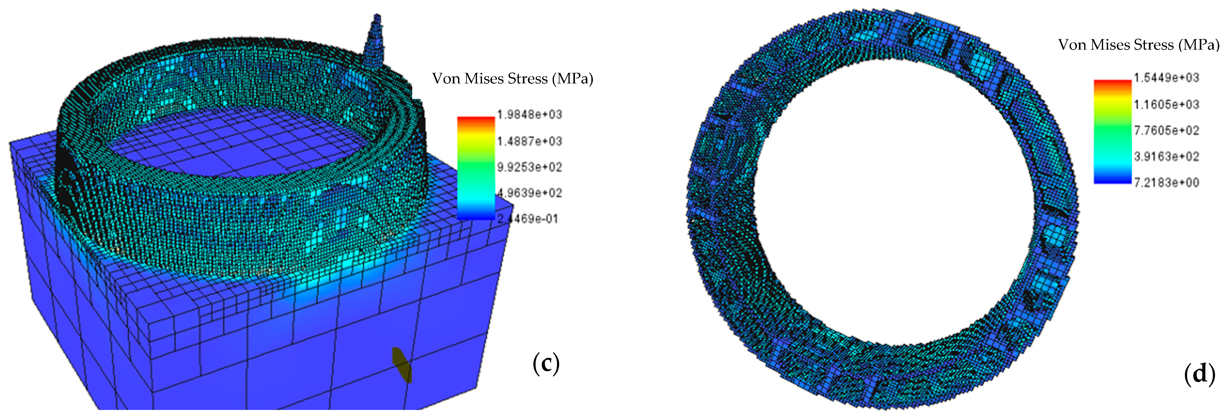
Results of this simulation are shown in
Figure 11 and
Figure 12, where it is shown that more residual stresses and correlative displacements are induced due to the manufacturing process, where even the extraction of the piece from the build platform releases some thermal stresses.
The simulations were carried out assuming isotropic elastic and plastic behavior for the candidate materials, using average bulk mechanical properties and manufacturing parameters shown in
Table 8. Although anisotropy is typically associated with SLM, several considerations support this modeling decision. It is important to highlight that the final component would likely be assembled from subparts fabricated in different orientations and joined via welding or mechanical interfaces, given that the precise build orientation and assembly process are undefined at this design stage.
Moreover, although studies such as Ülker et al. [
49] or Jiao et al. [
50] highlight the influence of anisotropy on stress concentration and fatigue life, the simulated stress levels in all cases are far below the yield strength of the materials, resulting in safety factors well above critical thresholds. Therefore, the global structural performance of the component is not compromised by the isotropic assumption. In addition, anisotropic behavior can be influenced by densification factors—in both micro and macro scales—which can be mitigated with optimal SLM process conditions due to its high cooling rates [
51].
Consequently, isotropy was assumed to ensure comparability and to reflect a feasible, yet generic, manufacturing scenario.
The simulation confirmed expectations, showing that the optimized model in Ti6Al4V is subjected to significantly higher temperatures during the process than the Al 6061 case, resulting in increased residual thermal stresses.
Considering the results obtained from both the pressure and force simulations, as well as those derived from the manufacturing process simulation, it can be observed that the total displacements—understood as deviations from the secure position of structural element caused by the combined mechanical loads and the thermal loads imposed by the AM process—are not significantly constraining for Ti6Al4V and Al 6061. However, the lower weight and cost associated with the aluminum alloy make it the most suitable option for the topologically optimized air intake, resulting in a 10,000 kg decrease approximately. This is numerically represented in
Table 9, with a cost comparison taking only the market price of powder into account and not the energy required to carry out the manufacturing process.
5. Conclusions
This work validates the synergistic application of TO and AM as a robust framework for the development of high-performance and lightweight aerospace components. By implementing this novel methodology in the manufacturing process, retrofitting of a supersonic turbofan air intake is achieved. The study illustrates how complex mechanical, aerodynamic, and manufacturability requirements can be successfully addressed through digital design and simulation workflows.
The implementation of the SIMP algorithm within Autodesk Fusion 360
® [
37] enabled a regenerative design process that led to a remarkable 71% weight reduction in the component, compared to its initial over-dimensioned configuration. Despite the reduction in material volume, structural performance was preserved across all tested load scenarios, validating the effectiveness of the optimized geometry.
Ti6Al4V, Al 6061, and PEEK mechanical performance and manufacturing process simulations were executed through finite element analysis. While Ti6Al4V exhibited the highest mechanical performance in terms of minimal displacement, Al 6061 emerged as the most balanced and viable solution, offering similar structural results with lower thermal stress, reduced weight, and significantly lower cost with a difference around 821,500 $, explained as the cost of material (100 $/kg for Ti6Al4V and 50 $/kg for Al 6061). PEEK, despite its favorable density and widespread use in other high-demand applications and extensive study for auxetic structures focused on energy and vibration absorption, was deemed unsuitable due to excessive deformation under load. However, the methodology created can be used to study any other possible application.
Moreover, the manufacturability analysis using Autodesk Netfabb Premium
® [
46] highlighted the real-world challenges of large-scale metal AM, particularly for titanium alloys, where higher processing temperatures lead to increased residual stress and distortion. These considerations further support the selection of Al 6061 as the most viable material for this application.
Beyond the numerical and mechanical advantages, this study also contributes to environmental sustainability in aerospace engineering. By reducing component mass, it directly supports lower fuel consumption and carbon emissions. Furthermore, additive manufacturing minimizes material waste and energy usage during production, aligning with emerging regulations and industry trends toward more sustainable aircraft design.
In summary, the novel combination TO–AM approach presented here represents a scalable and efficient pathway for designing next-generation aerospace components.
