Article

Support-Vector-Regression-Based Intelligent Control Strategy for DFIG Wind Turbine Systems

1
Department of Electrical Engineering, Faculty of Engineering and Technology, Jamia Millia Islamia, New Delhi 110025, India
2
Department of Electrical Engineering, Netaji Subhash University of Technology, Azad Hind Fauz Marg, Sector-3, Dwarka, New Delhi 110045, India
3
Department of Electrical Engineering, Galgotias College of Engineering and Technology, Greater Noida 201306, India
4
Department of Electrical Engineering, College of Engineering, Princess Nourah bint Abdulrahman University, P.O. Box 84428, Riyadh 11671, Saudi Arabia
5
Al Rowad International Schools, Al Nuzha, Riyadh 11673, Saudi Arabia
*
Author to whom correspondence should be addressed.
Machines 2025, 13(8), 687; https://doi.org/10.3390/machines13080687
Submission received: 20 June 2025 / Revised: 24 July 2025 / Accepted: 31 July 2025 / Published: 5 August 2025
(This article belongs to the Special Issue Modelling, Design and Optimization of Wind Turbines)

Abstract

Achieving sustainable energy goals requires efficient integration of renewables like wind energy. Doubly fed induction generator (DFIG)-based wind turbine systems (WTSs) operate efficiently across a range of speeds, making them well-suited for modern renewable energy systems. However, sudden wind speed variations can cause power oscillations, rotor speed fluctuations, and voltage instability. Traditional proportional–integral (PI) controllers struggle with such nonlinear, rapidly changing scenarios. A control approach utilizing support vector regression (SVR) is proposed for the DFIG wind turbine system. The SVR controller manages both active and reactive power by simultaneously controlling the rotor- and grid-side converters (RSC and GSC). Simulations under a sudden wind speed variation from 10 to 12 m per second show the SVR approach reduces settling time significantly (up to 70.3%), suppresses oscillations in rotor speed, torque, and power output, and maintains over 97% DC-link voltage stability. These improvements enhance power quality, reliability, and system performance, demonstrating the SVR controller’s superiority over conventional PI methods for variable-speed wind energy systems.

1. Introduction

1.1. Background Research

Wind power has emerged as a key component of sustainable energy and is continuously enhancing electricity production worldwide, with an installed capacity of 117 GW by 2024 [1,2,3,4]. To transform wind energy, wind turbine systems (WTSs) use three primary processes: capturing kinetic energy using blades, converting this energy into mechanical torque via the rotor, and producing electricity using an electromechanical system. Nevertheless, rotor speed and mechanical torque variations brought on by wind variability impact system stability and DC-link voltage [5]. The DFIG remains dominant over other technologies due to its capacity to lower mechanical stress and provides financial benefits compared to permanent magnet or full-scale synchronous generators.

1.2. Motivation for the Research

Despite being straightforward and popular, proportional–integral (PI) controllers’ fixed parameters limit their flexibility in the face of variable wind and nonlinear conditions. This paper presents an SVR-based controller that provides accurate real-time control with minimal computational complexity to address these limitations. Under a variety of operating conditions, dynamic response, adaptability, and system stability are improved when the PI controller is replaced with SVR.

1.3. Literature Review

The preference for PI controllers stems from their ease of use and implementation. They are frequently used to control grid-side and rotor-side converters in DFIG-based WTSs, guaranteeing active and reactive power control [6]. However, their fixed-parameter design limits flexibility under dynamic and nonlinear conditions, which reduces performance during disruptions like voltage swells and dips. Set-point weighting has been introduced in advanced designs (2DOF PI controllers) to enhance power quality, reduce overshoot, and improve disturbance rejection [7,8,9,10,11].
Soft computing approaches have been investigated to further address the limitations of traditional PI controllers. The performance of fuzzy logic controllers (FLCs) depends heavily on the design of membership functions and rule bases, but they can handle nonlinearities without the need for exact system models [12,13,14,15,16]. Although they can model complex nonlinear behaviors and have strong learning capabilities, artificial neural networks (ANNs) are difficult to implement in real-time systems and require large training datasets. The adaptive neuro-fuzzy inference system (ANFIS) increases accuracy and adaptability by combining the advantages of ANNs and FLCs, but it has significant computational complexity and long training periods [17,18,19,20,21,22,23,24].
Recent advanced AI/ML methods have been applied to wind energy control and forecasting. For example, Wang et al. (2025) presented a calibrated LSTM (C-LSTM) model, which achieved improved wind power forecasting accuracy [25]. XGBoost-based approaches have also shown promise; a hybrid XGBoost + LTC model reached a normalized MAE of 0.0856, outperforming standalone XGBoost and LSTM models, though performance dipped during high turbulence [26]. Furthermore, a Bayesian-tuned XGBoost model (BH-XGBoost) yielded lower RMSE and higher R2 compared to SVR, LSTM, and ANFIS methods.
An effective machine learning technique for control in DFIG-based WTSs is SVR, which is derived from support vector machines (SVMs). With its high generalization ability and low risk of overfitting, SVR proves to be a powerful model for nonlinear relationships. Comparative studies have shown that SVR controllers outperform conventional PI controllers in various scenarios by providing increased stability, reduced overshoot, and faster responses. SVR is well-suited for real-time wind energy applications since it can adapt to changing system conditions without the need for manual intervention [27]. PI controllers remain popular in control systems due to their ease of use and efficiency in linear situations; however, their limitations in dynamic and nonlinear situations necessitate exploring alternative approaches. Although promising, fuzzy, ANN, and ANFIS-based controllers are limited by their computational load, training requirements, and design complexity. In managing the complexities of DFIG-based WTSs, SVR-based controllers offer a compelling alternative by combining flexibility, resilience, and strong performance. A comparative summary of commonly used control methods in DFIG-based WTSs is presented in Table 1.

1.4. Problem Statement

Due to their fixed gains and lack of adaptability, traditional PI controllers in DFIG-based WTSs often perform poorly under dynamic grid conditions. SVR, though requiring careful design for real-time use, offers a data-driven alternative with greater precision and flexibility. The main aim is to generate a control strategy that combines SVR’s flexibility with minimal computational overhead to ensure quick response and reliable performance across varying operating conditions.

1.5. Purpose of the Research

The main goal of this paper is to design a control system based on SVR to improve the dynamic performance of wind energy systems. The SVR controller accurately controls both RSC and GSC to suppress rotor speed spikes, reduce torque oscillations, and stabilize DC-link voltage. The SVR approach offers greater computational efficiency, real-time responsiveness, and adaptability compared to PI and other AI-based techniques. The aim is to deliver a scalable, data-driven solution for modern wind energy applications.

1.6. Research Goals

  • To create a single intelligent control approach based on support vector regression (SVR) for the coordinated control of the RSC and GSC in DFIG-based wind turbine systems (WTSs).
  • To lessen mechanical torque oscillations and rotor speed overshoot in windy and variable conditions.
  • To strengthen DC-link voltage regulation and the system’s capacity to effectively control the flow of active and reactive power.
  • To evaluate and validate the performance of the proposed SVR controller against conventional PI and other advanced controllers through extensive time-domain simulations.
  • To establish the computational efficiency, robustness, and real-time applicability of the SVR-based control framework in dynamic and fault-prone grid environments.

1.7. Contributions

  • Designed an SVR-based intelligent controller for real-time optimization of RSCs and GSCs in DFIG-based wind turbine systems.
  • Improved dynamic performance with ~17.2% less rotor speed overshoot and 30.2% faster settling time compared to PI controllers.
  • Outperformed hybrid ANFIS-PI controllers with 8.3% lower overshoot, 12.4% quicker settling, and reduced computational complexity.
  • Achieved accurate, scalable control without requiring large training datasets, ensuring feasibility for real-time grid integration.
By integrating machine learning techniques with low-complexity computation, the developed SVR controller significantly improves dynamic control in DFIG-WTS. It demonstrates measurable reductions in rotor speed overshoot and settling time when compared to both PI and hybrid ANFIS-PI methods, without relying on large-scale training data. These results establish its practicality for real-time grid applications. The structure of the paper includes: system modeling (Section 2), controller development (Section 3), performance validation (Section 4), limitations and discussions (Section 5), and final conclusions (Section 6).

2. Mathematical Modeling and Configuration of WECS Components

This section presents a comprehensive mathematical model of the DFIG integrated with a WECS, addressing both steady-state and dynamic conditions. The aim is to understand DFIG behavior under variable wind and grid disturbances. The modeling begins with the steady-state equivalent circuit, followed by dynamic equations using Park’s d-q transformation to derive stator/rotor voltages, currents, and active/reactive power essential for developing effective control strategies [28].

2.1. System Configuration

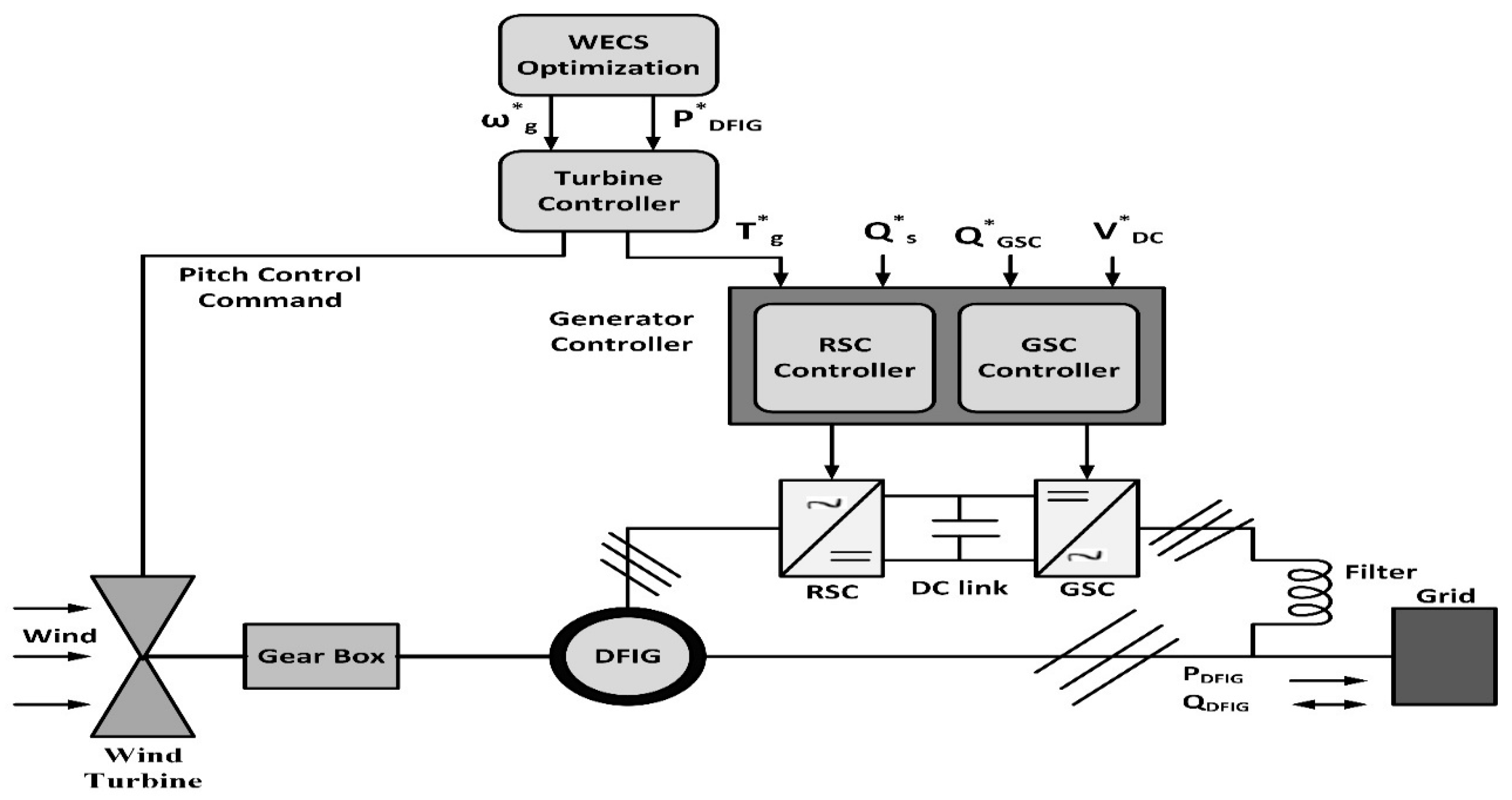
The DFIG-based WECS includes a wind turbine, gearbox, generator, converters, DC-link capacitor, coupling transformer, and protection system, as shown in Figure 1. The DFIG is a wound rotor machine with the stator directly connected to the grid and the rotor linked via a partially rated AC/DC/AC converter handling only 26–30% of total power. This setup allows full control using a variable frequency drive with IGBT-based converters. The stator operates at 50 Hz, while the rotor is supplied at variable frequency. The converter system consists of an RSC and GSC connected through a DC-link capacitor. The RSC controls rotor current to regulate torque and excitation. Operating in bidirectional power mode, the DFIG supports both sub-synchronous and super-synchronous operation [29,30,31].
Figure 2 illustrates the model of the DFIG-based WECS. At the highest level, the system adjusts turbine speed to extract maximum wind power—this is governed by a mechanical system control.

2.2. Dynamic Modeling of DFIG

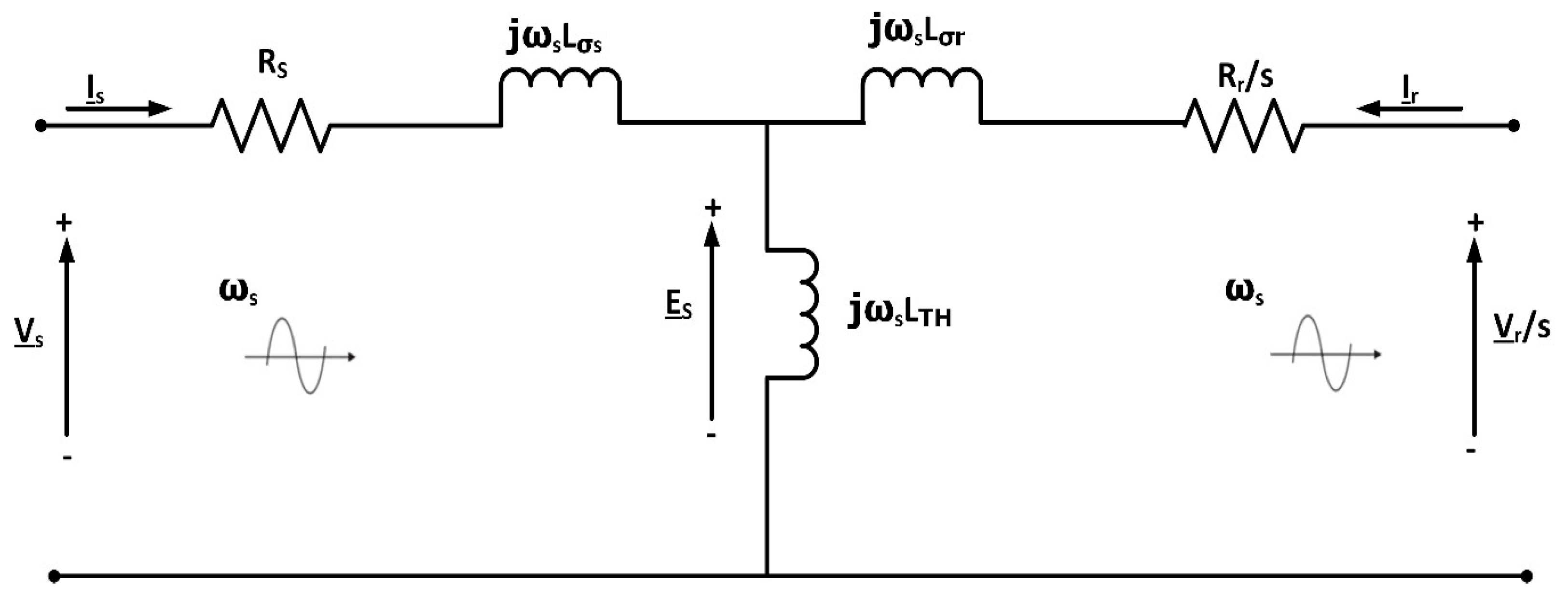
Figure 3 illustrates the stator-referring steady-state equivalent circuit of the DFIG, corresponding to Equations (1)–(10), which describe the voltage, flux, and power expressions shown below:
Voltages and the fluxes referring to the stator are [32]:
V S = R s I s + j ω s L σ s I s + j ω s L m ( I s + I r )
V r S = R r S I r + j ω s L σ r I r + j ω s L m ( I s + I r )
ψ s = L s I s + L m I r
ψ r = L r I r + L m I s
Stator and rotor are active and reactive as:
P s = 3 R s I s 2 + 3 ω s L m I m { I s I r * }
Q s = 3 ω s L s I s 2 + 3 ω s L m R e { I r I s * }
P r = 3 R r I r 2 + 3 s ω s L m I m { I s I r * }
Q r = 3 s ω s L r I r 2 + 3 s ω s L m R e { I s I r * }
Electromagnetic torque is given by:
T e m = 3 L m σ L r L s p . I m { ψ s ψ r * }
where σ = ( 1 L m 2 L s L r ) .
Mechanical power is:
P m = P s + P r

2.2.1. αβ Modeling

The stator voltages are as below [33,34]:
V α s = R s i α s + d d t ψ α s
V β s = R s i β s + d d t ψ β s
The rotor voltages are as follows:
V α r = R r i α r + d d t ψ α r + ω m ψ β r
V β r = R r i β r + d d t ψ β r ω m ψ α r
Similarly, the fluxes are as follows:
ψ α s = L s i α s + L m i α s
ψ β s = L s i β s + L m i β s
ψ α r = L r i α r + L m i α r
ψ β r = r i β r + L m i β s
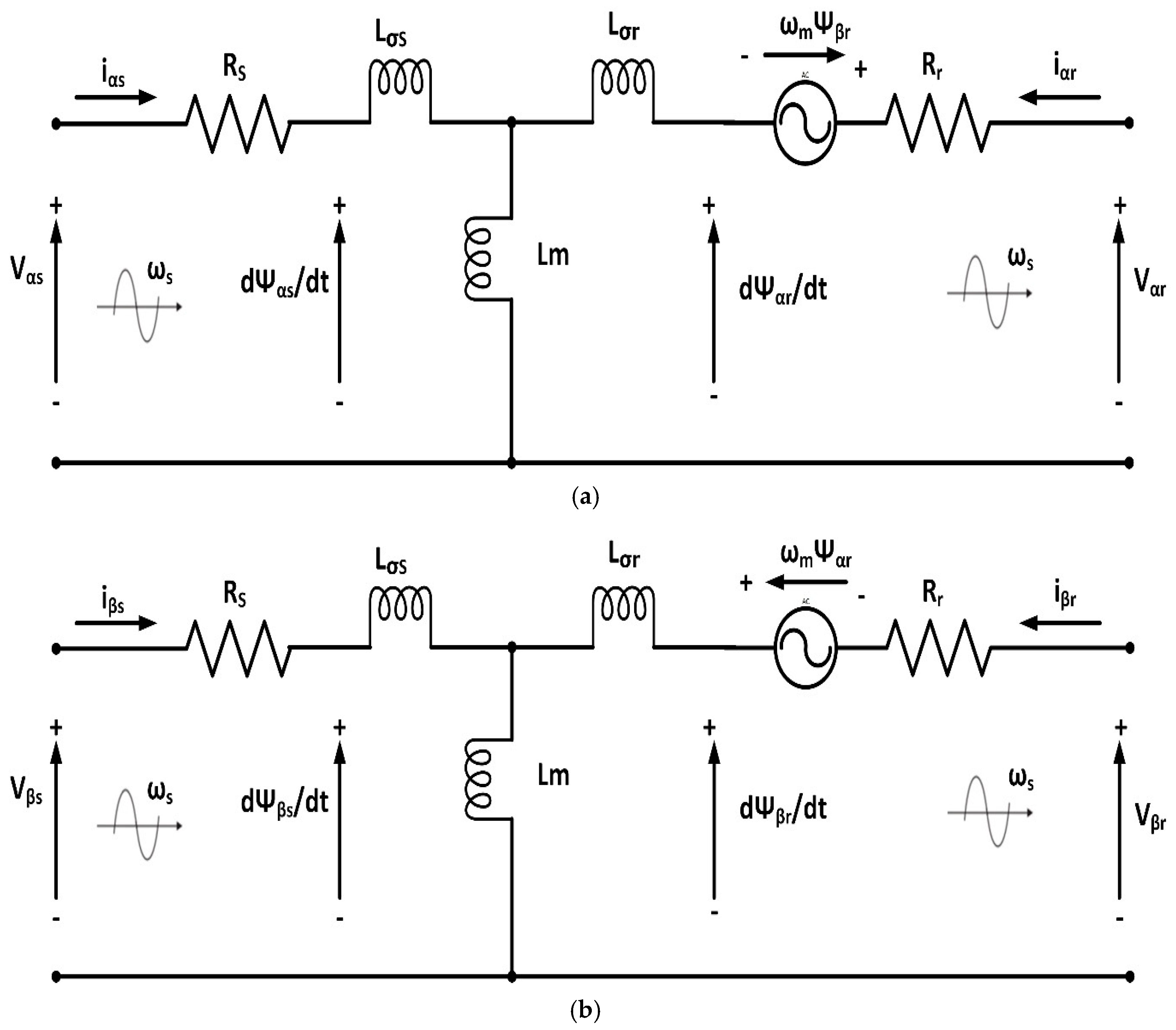
Figure 4a,b present the αβ-equivalent circuits for the stator and rotor, which correspond to Equations (11)–(18). The equivalent circuit diagram is shown below:
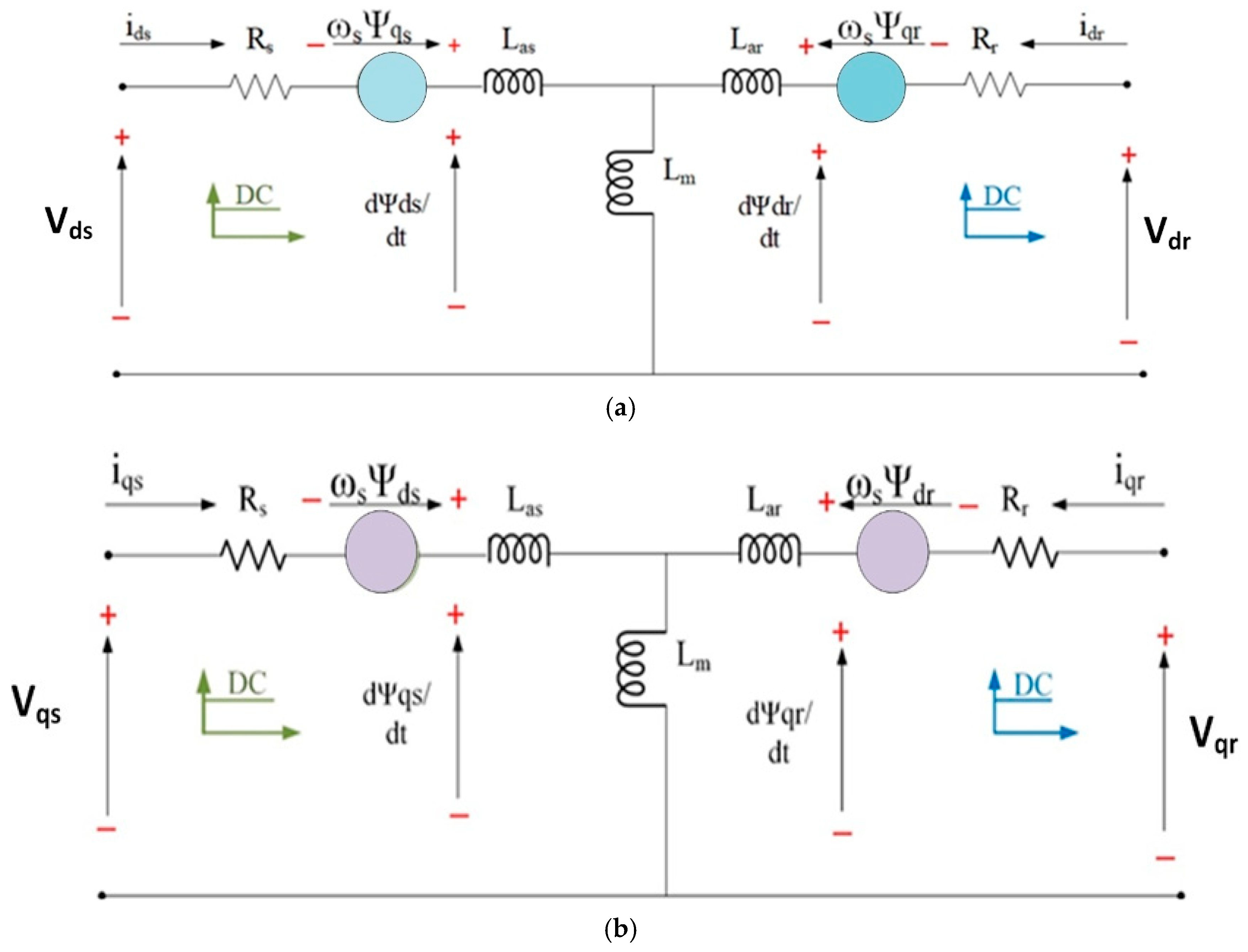
Figure 5a,b show the dq reference frame equivalent circuits that support the derivation of Equations (24)–(35), representing the transformed voltage and flux relationships. The stator and rotor mention frame powers as below:
P s = 3 2 v α s i α s + v β s i β s
Q s = 3 2 v β s i α s v α s i β s
P r = 3 2 v α r i α r + v β r i β r
Q r = 3 2 v β r i α r v α r i β r
The equation for electromagnetic torque:
T e m = 3 2 p ψ β r i α r ψ α r i β r

2.2.2. dq Modeling of DFIG

The voltage vectors for both the stator and rotor are formulated as follows [34]:
V s V d s = R s i d s + d ψ d s d t ω s ψ q s V q s = R s i q s + d ψ q s d t + ω s ψ d s
V r V d r = R r i d r + d ψ d r d t ω r ψ q r V q r = R r i q r + d ψ q r d t + ω r ψ d r
The stator and rotor flux vectors are represented in Equations (26) and (27), respectively:
ψ s ψ d s = L s i d s + L m i d r ψ q s = L s i q s + L m i q r
ψ r ψ d r = L m i d s + L r i d r ψ q r = L m i q s + L r i q r
d ψ q s d t = ω b V q s ω e ω b ψ d s + R s χ l s ( ψ m q + ψ q s )
d ψ d s d t = ω b V d s + ω e ω b ψ q s + R s χ l s ( ψ m d + ψ d s )
d ψ q r d t = ω b V q r ( ω e ω r ) ω b ψ d r + R r χ l r ( ψ m q ψ q r )
d ψ d r d t = ω b V d r + ( ω e ω r ) ω b ψ q r + R r X l r ( ψ m d ψ d r )
Solving (26) to (31) give [33,34,35]:
I q s = 1 σ L s ψ q s L m σ L s L r ψ q r
I d s = 1 σ L s ψ d s L m σ L L r ψ d r
I q r = L m σ L s L r ψ q s + 1 σ L s ψ q r
I d r = L m σ L s L r ψ d s + 1 σ L s ψ d r

2.3. DFIG in State-Space Equations

State-space modeling is essential for dynamic simulation using tools like MATLAB R2023b, particularly for analyzing system behavior under transient conditions. State space refers to a coordinate system defined by “n” state variables with time as the independent variable. These variables typically belongs to energy-storing elements such as inductors and capacitors. The fundamental state-space equation is given as follows:
( x t = A x t + B u ( t ) y t = C x t + D u ( t ) )
Equation (36) is for a direct time invariant framework, where A, B, C, and D are state, info, yield, and feed forward grids, respectively. Equation (37) is for a straight time variation framework, where A, B, C, and D are time subordinate grids.
( x t = A ( t ) x t + B ( t ) u ( t ) y t = C ( t ) x t + D ( t ) u ( t ) )
Substituting Equations (32)–(35) into (24) to (25) gives [36]:
d ψ q s d t = r s ψ q s σ L s ω e ψ d s + r s L m σ L s L r ψ q r + V q s
d ψ d s d t = ω e ψ q s r s σ L s ψ d s + r s L m σ L s L r ψ q r + V d s
d ψ q r d t = r s L m σ L s L r ψ q s ( ω e ω r ) ψ d r r r σ L r ψ q r + V q r
d ψ d r d t = r s L m σ L s L r ψ d s + ( ω e ω r ) ψ q r r r σ L r ψ d r + V d r
The dynamic modeling of DFIG in Equations (38)–(41) is performed in the synchronous dq reference frame aligned with the stator flux. Here, ωₑ represents the synchronous electrical angular frequency of the stator, while ωᵣ is the mechanical angular speed of the rotor. The slip frequency is defined as ω s l i p = ωₑ − ωᵣ. All quantities are referenced to the stator frame using standard dq transformations, with power generation considered as the positive direction.
Equations (38)–(41) are written in a state-space matrix:
ψ q s ψ d s ψ q r ψ d r = r s σ L s ω e r s L m σ L s L r 0 ω e r s σ L s 0 r s L m σ L s L r r s L m σ L s L r 0 r s σ L r ( ω e ω r ) 0 r r L m σ L s L r ( ω e ω r ) r r σ L s ψ q s ψ d s ψ q r ψ d r +   1 0 0 0 0 1 0 0 0 0 1 0 0 0 0 1 v q s v d s v q r v d r

2.4. Active, Reactive Power and Torque Calculation

Every one of the conditions is an IM condition. At the point when the enlistment engine fills in as a generator, the course of the current will be inverse. The equations for active and reactive power in the stator and rotor are presented in Equations (43)–(46), respectively [37,38,39,40]:
P s = 3 2 ( V d s i d s + V q s i q s )
Q s = 3 2 ( V q s i d s V d s i q s )
P r = 3 2 V d r i d r + V q r i q r
Q r = 3 2 V q r i d r V d r i q r
P T o t a l = P s + P r
Q T o t a l = Q s + Q r
The speed dynamics of the rotor in the DFIG is given as:
d d t ω r = P 2 J ( T m T e C f ω r )
T m is written as:
T e = 3 2 ( ψ q s i d s ψ d s i q s )
Table 2 summarizes the DFIG electrical machine parameters [41], and Table 3 gives the generator’s ratings and parameters [41].

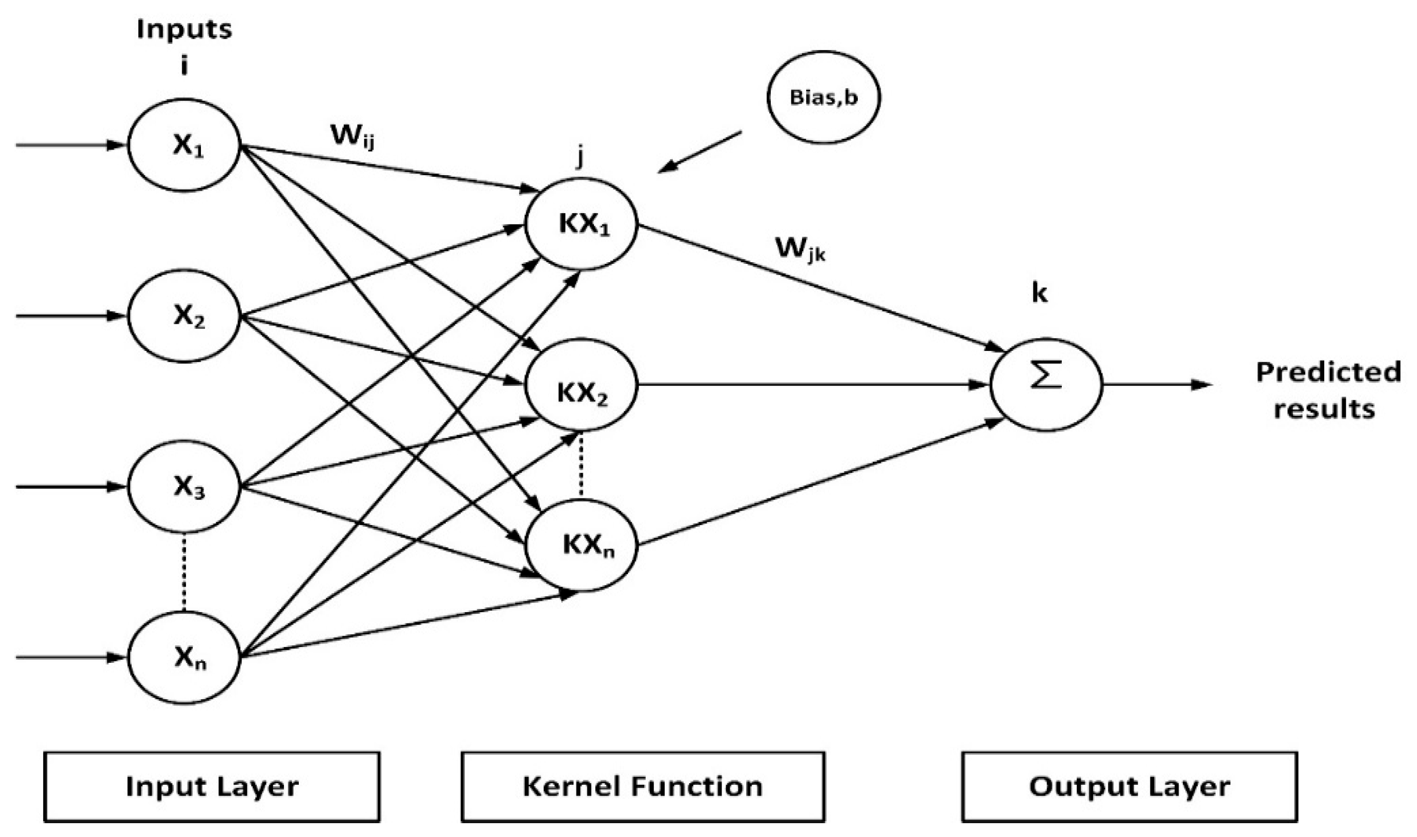
3. Proposed Support Vector Regression (SVR)-Based Controller

The proposed control system uses SVR inside the WTS to control essential parameters, including rotor speed, DC-link voltage, and reactive power. Key performance criteria are percentage overshoot, settling time, and grid disturbance robustness; SVR-based controller performance is calculated in MATLAB/Simulink. To confirm the pre-eminence of the SVR controller in dynamic adaptation and computational efficiency, its performance is contrasted with that of conventional PI-based controllers. Using a kernel-driven approach, SVR converts input characteristics into a higher-dimensional space, creating a very flexible regression model. Unlike artificial neural networks (ANNs), which require large datasets and extended training over several epochs, SVR maximizes model complexity by depending just on a selective sub-set of training points called support vectors. Its lower computational load helps to speed up the training process and improve fit for real-time applications. The PI and SVR results obtained here were reused in the authors’ follow-up study [42], which expanded the comparison to include additional advanced control strategies, using the same simulation benchmarks. Figure 6 reveals the structural diagram of the SVR-based controller.
The SVR control architecture, illustrated in Figure 6, comprises key phases: (1) receiving inputs like rotor speed error and DC voltage deviation, (2) mapping these inputs to a kernel function, (3) selecting support vectors from training data, (4) predicting control outputs such as reference rotor current or voltage correction, and (5) generating control signals for the RSC and GSC. Figure 7 outlines the SVR controller’s flowchart, which includes two validation steps. The first checks prediction accuracy after initial training—if the error exceeds a set threshold, the model is retrained with updated parameters or additional data. Once the prediction error is minimized, the trained model is saved and used for dynamic system validation, evaluating performance metrics like voltage stability, settling time, and overshoot. If performance meets criteria, deployment proceeds; otherwise, the process loops for further refinement. The SVR model parameters are listed in Table 4.
Although the SVR model uses 42,977 support vectors, its prediction latency remains low (~0.3 ms), meeting real-time constraints. Unlike models such as ANFIS, which involve continuous rule tuning and adaptive fuzzy logic [17,18], SVR uses a fixed-kernel approach, resulting in faster and more predictable inference. This makes SVR particularly suitable for real-time control in wind energy systems. The SVR controller structure implemented in this work, particularly the training approach and kernel configuration, was later extended and evaluated alongside other AI-based controllers in [42], highlighting its scalability and effectiveness across varying model complexities.
The GSC and RSC are generally managed by WTSs using nested control loops and a multi-level control strategy. By giving inner and outer loops distinct tasks, this hierarchical structure enhances dynamic stability, response time, and control accuracy. While the rotor-side loop controls rotor speed (outer) and torque (inner), the grid-side loop controls DC-link voltage (outer) and active power (inner). By these synchronized loops, stable voltage, current, and rotor speed are guaranteed, facilitating dependable grid interaction and effective energy conversion. The suggested SVR-based controller further improves real-time performance and flexibility as compared to convention techniques.

Implementation of Proposed SVR-Based Controller in WECS Model

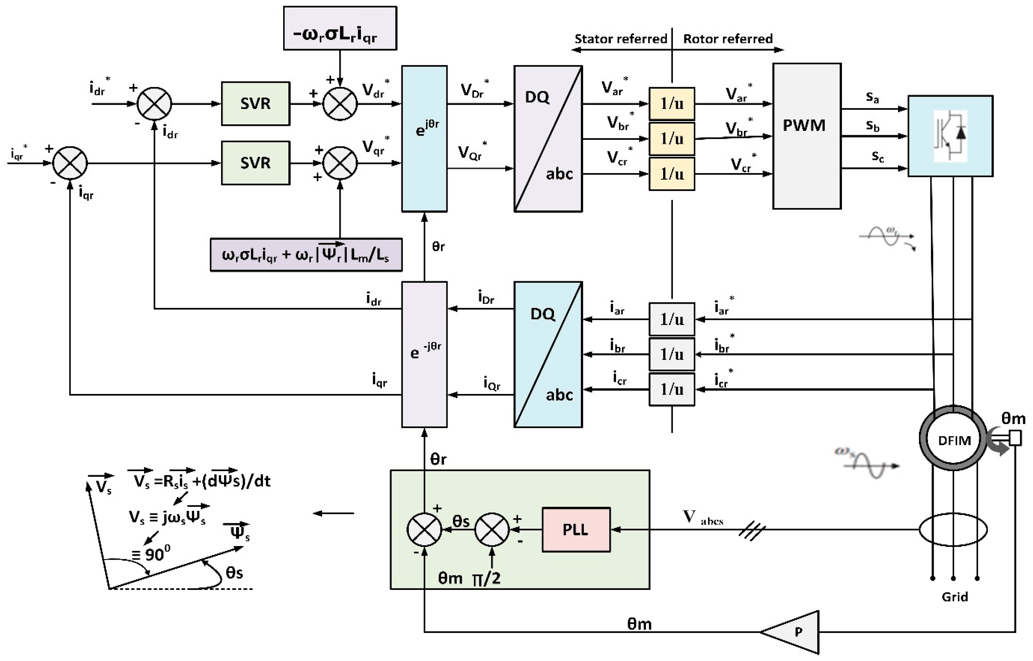
SVR controllers are used in this configuration to regulate the inner and outer loops of the GSC and RSC to improve control accuracy, dynamic response, and system dependability. Figure 8 illustrates how the inner loop controls mechanical torque and the outer loop SVR controller controls rotor speed to provide the best RSC performance in a range of wind conditions.
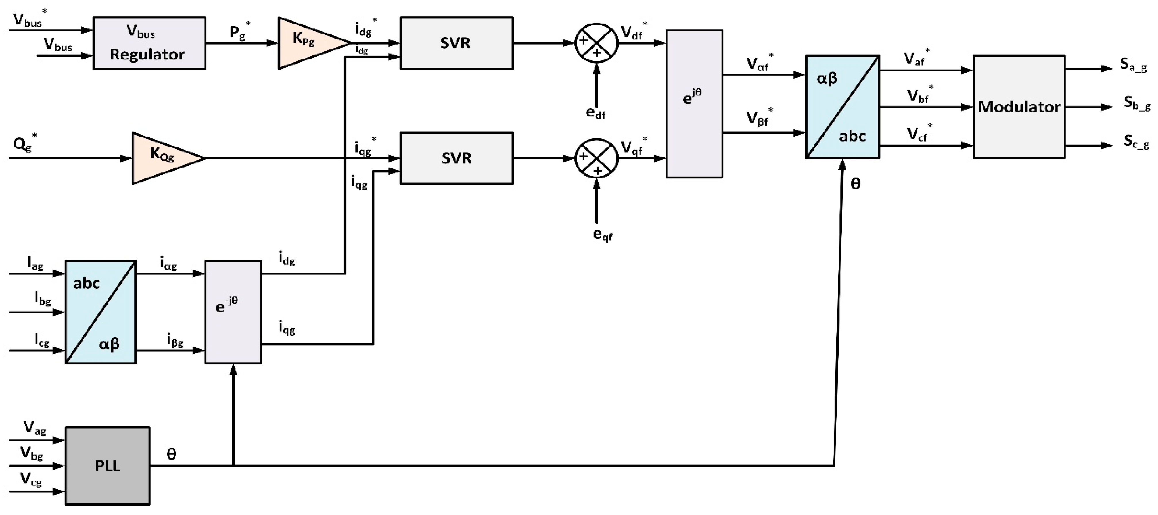
Similarly, SVR controllers are used in both the inner and outer control loops when the proposed SVR-based control approach is applied to the GSC, as illustrated in Figure 9. In this configuration, the outer loop SVR controller maintains the necessary DC-link voltage across the capacitor, while the inner loop SVR controller ensures precise current control. Particularly under variable wind and grid conditions, this dual-layer SVR-based control improves the dynamic response, voltage stability, and overall performance of the GSC converter.
To rigorously assess the real-time performance of the control system, the SVR-based controller was designed and implemented in the MATLAB/Simulink environment under a dynamic test scenario. This scenario effectively simulates real-world wind fluctuation conditions and provides insight into the controller’s capability to maintain system stability and optimal performance.
The wind speed test signals shown in Figure 10 are applied at 10 s, where wind speed is varied from 10.0 m/s to 12.0 m/s, in order to assess the ability of the WS. The wind speed range of 10.0 to 12.0 m/s was selected to focus on the Region II–III transition, where torque nonlinearity and rated power onset challenge conventional control methods. This mid-range interval is ideal for evaluating dynamic control response and adaptability, making it suitable for testing the robustness of the SVR-based controller.
For training and evaluation, the SVR model was built using a structured dataset partitioning method:
  • Training Set (65%)—Used to train the SVR model by optimizing support vectors, kernel function parameters (e.g., RBF kernel width), and penalty coefficients. This phase ensures the model captures the underlying dynamics of the system based on simulation data.
  • Validation Set (15%)—Utilized during the training process to fine-tune the SVR model and prevent overfitting. This subset helps adjust the model to generalize well to new, unseen data conditions.
  • Testing Set (20%)—Independently used to evaluate the predictive accuracy and control performance of the trained SVR model.
Figure 11 presents a time-domain comparison between the actual control signal and the SVR-predicted output for the GSC after a simulation runtime of 20 s. The visual representation highlights the accuracy and consistency of the SVR model in tracking and replicating the control signal behavior, demonstrating its suitability for real-time regulation of the GSC in a DFIG-based WTS.
To objectively validate the predictive capability of the SVR model, a comprehensive quantitative analysis was conducted using several well-established performance evaluation metrics. These include mean squared error (MSE), root mean squared error (RMSE), mean absolute error (MAE), and the coefficient of determination (R2). These metrics provide insights into the accuracy, reliability, and generalization ability of the trained SVR controller in predicting the required control actions based on dynamic system inputs.
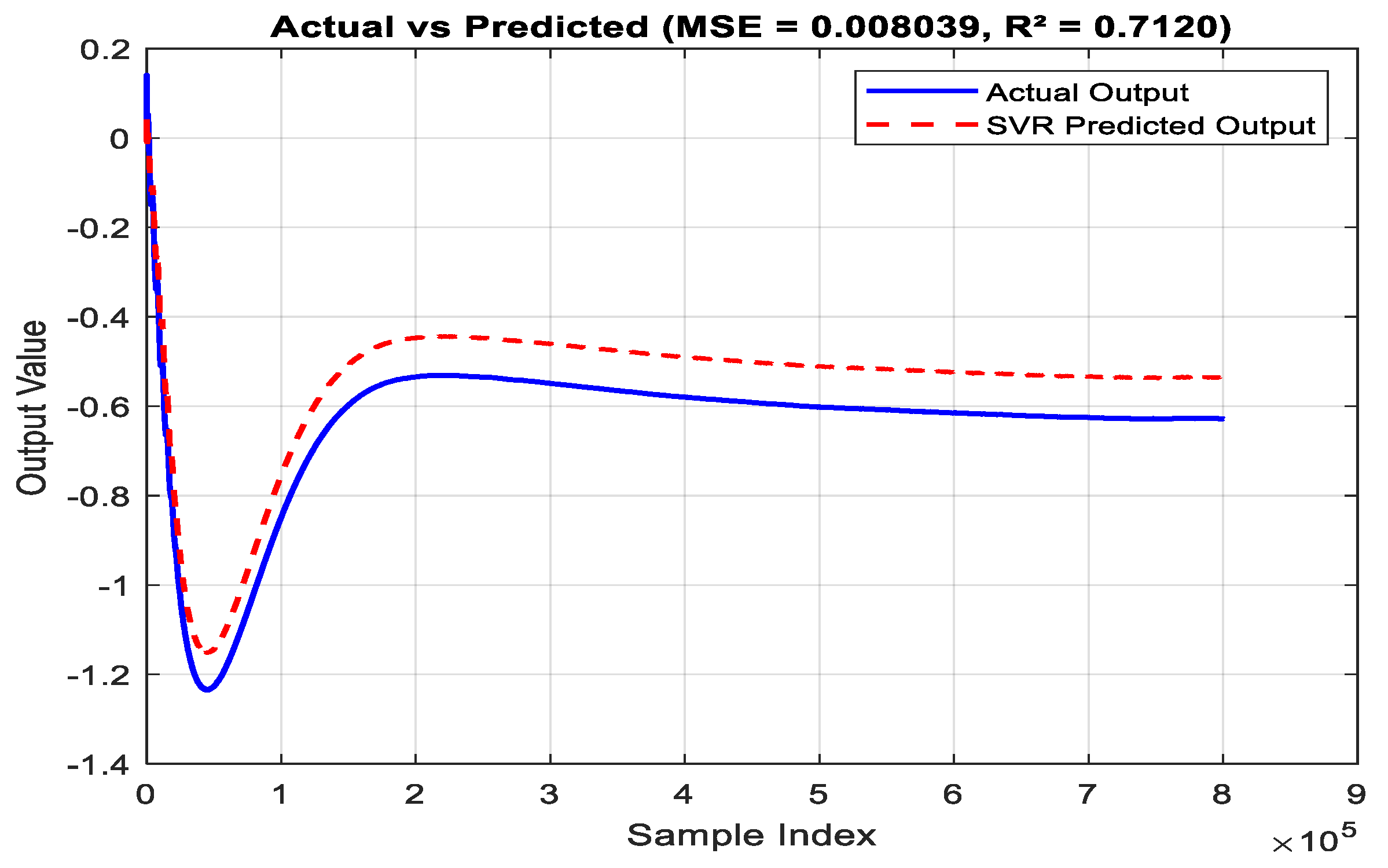
The performance evaluation results, as detailed in Table 5 and Table 6, confirm the high accuracy, consistency, and robustness of the proposed SVR-based controller for both the GSC and RSC in a DFIG-based WECS. A minimal MSE of 0.0067 and a strong R2 of 0.81 suggest that the SVR model provides highly reliable predictions for GSC control, even under variable input conditions. The SVR controller exhibits excellent generalization across dynamic, nonlinear conditions such as fluctuating wind speeds and grid disturbances. A time-domain comparison, shown in Figure 12, further supports the model’s real-time tracking accuracy, with minimal deviation between predicted and actual outputs. As observed in Figure 12, the SVR controller output exhibits a minor underestimation of the transient response and a slight steady-state error. This is attributed to the Gaussian kernel’s smoothing characteristics and the generalization setting of the kernel scale. Furthermore, the limited representation of extreme transitions in the training dataset contributes to this behavior. Nevertheless, the controller maintains high prediction accuracy and robust performance, as reflected in the R2 value of 0.71 and low MSE of 0.008.
The SVR’s large support vector count reflects training data resolution but does not hinder online performance, as runtime prediction relies only on dot product evaluations with stored vectors. These results underscore the SVR model’s practical applicability in real-time wind energy systems, offering low computational complexity, rapid response, and stable control performance under varying operational conditions.

4. Result and Discussion

4.1. Computational Performance and Real-Time Feasibility

The SVR controller was deployed using a MATLAB Function block, leveraging pretrained support vectors and coefficients. Since prediction involves only kernel evaluations and weighted summation, the model avoids real-time retraining or iteration. This structure ensures low computational load and rapid response, making the controller suitable for real-time wind turbine applications. Compared to ANN or ANFIS-based controllers, the SVR model offers faster execution and simpler deployment, especially on resource-constrained embedded platforms.

4.2. Statistical Validation of SVR Performance

To evaluate the consistency and robustness of the SVR controller under repeated trials, a statistical analysis was conducted using 30 Monte Carlo simulations with slight variations in wind profiles and measurement noise. The analysis focused on key performance indicators: rotor speed overshoot, torque overshoot, settling time, and DC-link voltage error. The mean, standard deviation (SD), and 95% confidence interval (CI) were calculated for each parameter. Results are summarized in Table 7.
These results demonstrate that the SVR controller maintains statistically stable performance across multiple trials, with very low variance and narrow confidence intervals. This reinforces its reliability and suitability for real-time applications in wind turbine systems. To evaluate system performance under dynamic wind conditions, a step input in wind speed from 10.0 m/s to 12.0 m/s was applied. The proposed SVR-based controller was implemented in MATLAB/Simulink to handle this variation.
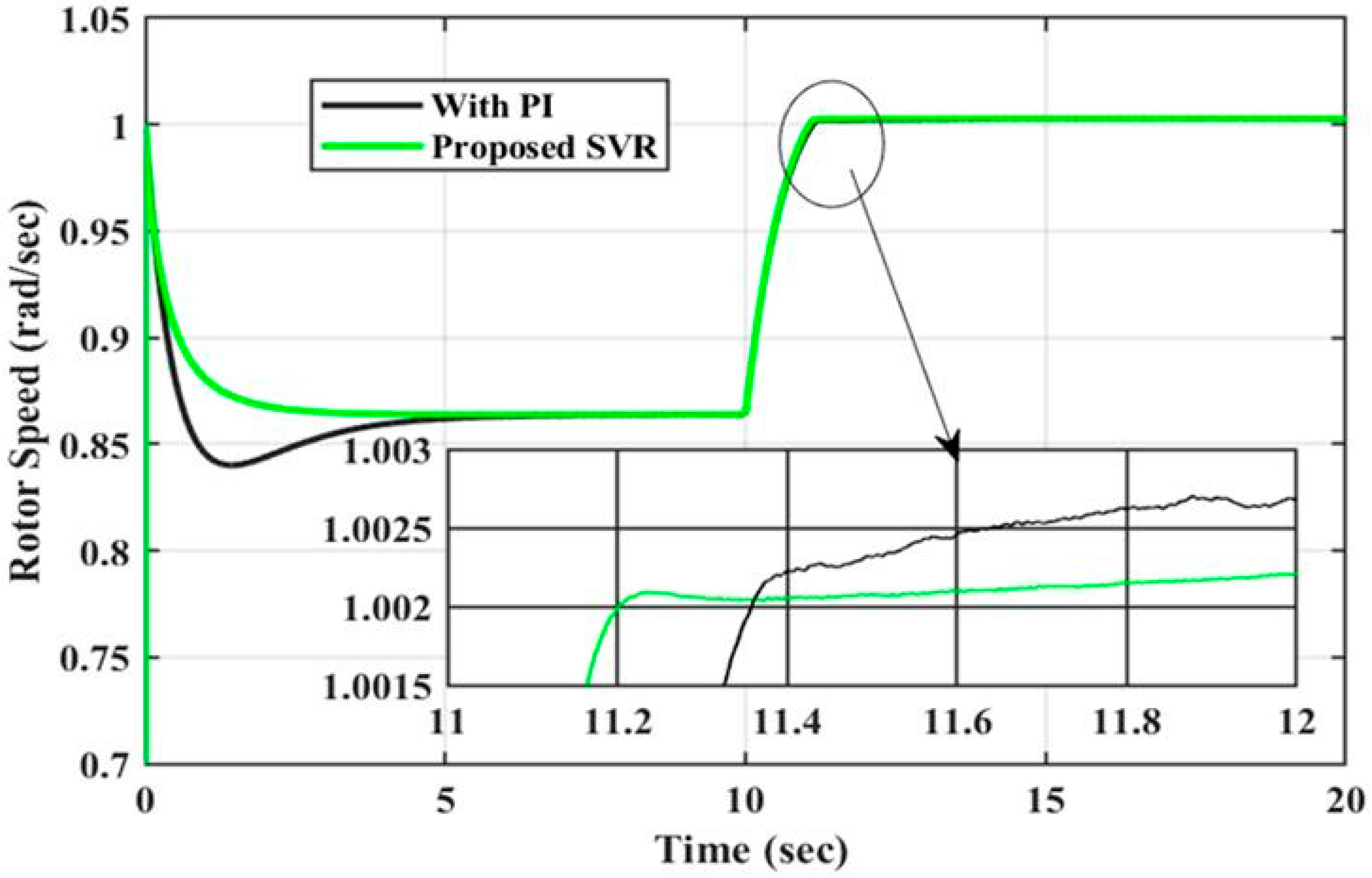
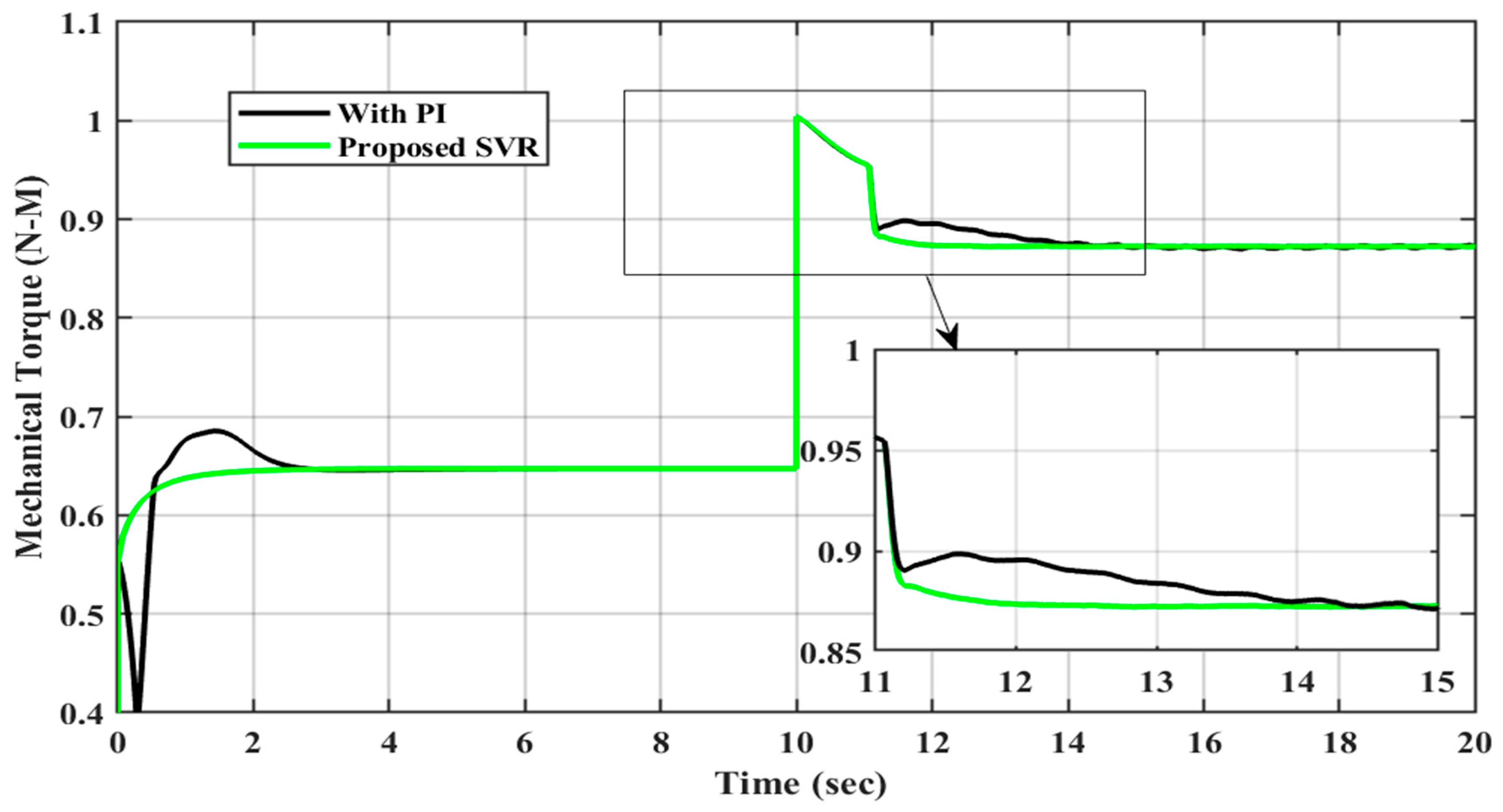
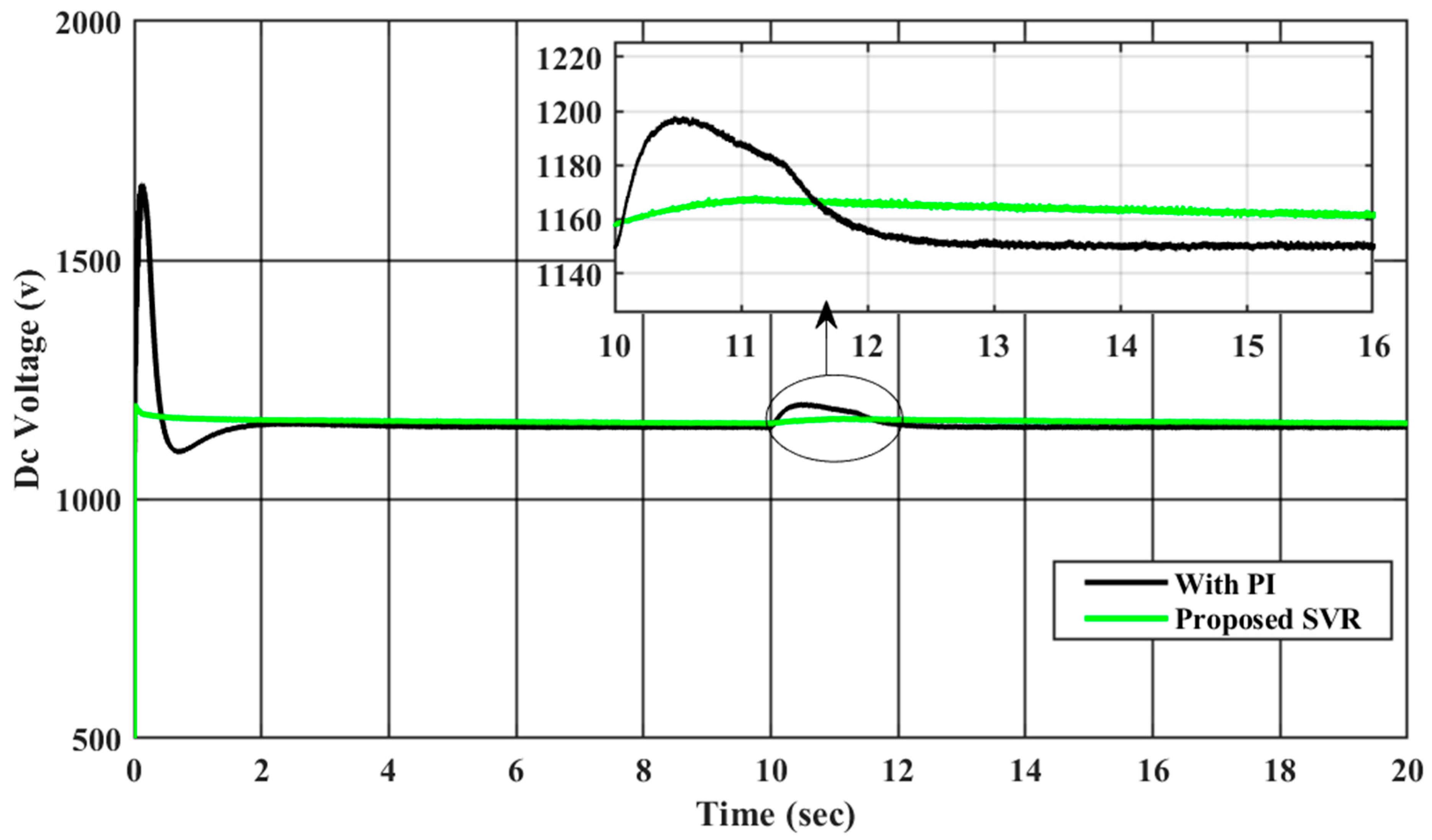
A comparative analysis is presented using Figure 13, Figure 14, Figure 15 and Figure 16, which illustrate the time-domain responses under two distinct control scenarios:
The baseline system using the standard PI controller.
The enhanced system implementing the proposed SVR-based controller.
Analyzing the results of the conventional PI controller and the proposed SVR-based controller reveals significant improvements in system response when the intelligent SVR approach is employed.
Figure 13 shows that the PI controller achieves a rotor speed overshoot of 6.5% with a 6 s settling time and a steady-state error of 0.0020. However, it struggles with minor oscillations and limited adaptability. In contrast, the SVR controller stabilized the rotor speed in just 1.8 s with a smooth and well-damped response, highlighting its superior adaptability to dynamic conditions.
Figure 14 illustrates similar trends for mechanical torque. The PI controller shows a 9% overshoot, 6 s settling time, and a steady-state error of 0.0040, along with residual oscillations that may cause mechanical wear. The SVR controller reduces torque overshoot to 1%, settles in 2 s, and eliminates steady-state error, ensuring greater mechanical stability.
As seen in Figure 15, active power output under PI control has a 14% overshoot, 6.5 s settling time, and 0.0030 error. SVR significantly improves this, with only 1% overshoot, 2.5 s settling time, and zero error, resulting in more stable and accurate power delivery to the grid.
Figure 16 highlights that the PI controller takes 8.5 s to regulate DC-link voltage, peaking near 1800 V with 6.5% overshoot and a 5 V steady-state error. SVR, however, maintains the voltage near 1100 V with only 1% overshoot, 2.5 s settling time, and zero error, ensuring better converter protection and grid stability.
Table 8 summarizes these outcomes, showing that the SVR controller outperforms the PI controller across all key metrics, achieving faster stabilization, lower overshoot, and complete elimination of steady-state errors in all evaluated parameters.
The analysis demonstrates that, in DFIG-based wind turbine systems, the SVR-based control approach provides significant advantages over conventional PI control. Rapid transients and nonlinearities can be handled accurately and effectively thanks to its regression-based adaptability. The SVR controller is ideal for contemporary renewable energy applications since it not only improves dynamic performance but also supports grid compliance, long-term reliability, and system protection.

5. Limitation of the Proposed Method

  • The SVR model has a relatively high number of support vectors (42,977), which represent approximately 10.7% of the dataset. This increases the model’s computational complexity and may limit scalability in real-time or embedded applications. Although this configuration yielded strong predictive accuracy, it reflects a trade-off between model performance and compactness.
  • The current work evaluates the SVR controller under a step-change wind profile, which, while effective for initial validation, does not encompass the full spectrum of dynamic operating conditions. Scenarios such as wind turbulence, random noise, and grid disturbances were not included in this study. Future work will extend testing to include these complex conditions to assess controller robustness and real-world applicability.
  • While experimental validation is highly valuable, it was not feasible within the current scope due to resource and infrastructure limitations. However, we fully acknowledge this limitation and agree that future work should involve hardware-in-the-loop (HIL) testing or real-time lab-scale implementation using digital control platforms (e.g., dSPACE, OPAL-RT, or FPGA-based controllers) to validate the controller’s practical performance, latency, and robustness under real-world disturbances.

6. Conclusions

This study presents an SVR-based control strategy tailored for coordinated control of GSCs and RSCs in DFIG wind systems and it is compared to the conventional PI controller. The SVR controller is ideally fit for real-time smart grid applications as it leverages machine learning within a streamlined control framework to significantly reduce computational complexity and enhance dynamic performance. As per the results, the SVR controller outperforms the PI controller by removing overshoot in rotor speed, torque, and active power and reducing settling time by up to 70.2%. Additionally, it guarantees over 97.4% DC-link voltage stability in a range of wind conditions, which helps to make system performance more dependable and seamless. The SVR method, in contrast to fixed-parameter PI controllers, can effectively adjust to dynamic, nonlinear conditions without requiring a large amount of training data. The results highlight SVR’s suitability as a high-performing, scalable alternative to traditional rule-based controllers for modern wind energy.

Author Contributions

Conceptualization, F.N. and I.N. and S.K.; methodology, S.K. and F.N.; software, F.N. and B.B.; validation, S.U., M.S. and I.N.; formal analysis, M.S. and B.B.; investigation, S.U. and F.N.; resources, F.N. and I.N.; data curation, F.N.; writing—original draft, F.N.; writing—review and editing, M.S. and S.U.; visualization, I.N.; supervision, S.K., I.N. and M.S.; project administration, S.U.; funding acquisition, S.U. All authors have read and agreed to the published version of the manuscript.

Funding

This research is funded by Princess Nourah bint Abdulrahman University Researchers Supporting Project number PNURSP2025R79, Princess Nourah bint Abdulrahman University, Riyadh, Saudi Arabia.

Data Availability Statement

The original contributions presented in this study are included in the article. Further inquiries can be directed to the corresponding author(s).

Acknowledgments

Princess Nourah bint Abdulrahman University Researchers Supporting Project number (PNURSP2025R79), Princess Nourah bint Abdulrahman University, Riyadh, Saudi Arabia.

Conflicts of Interest

The authors declares no conflict of interest.

References

  1. GWEC: Global Wind Report 2024. Global Wind Energy Council. 2024. Available online: https://www.gwec.net/ (accessed on 2 June 2025).
  2. Hete, R.R.; Shrivastava, T.; Dash, R.; Anupallavi, L.; Fathima, M.; Reddy, K.J.; Dhanamjayalu, C.; Mohammad, F.; Khan, B. Design and develop a PI controller for DFIG grid integration using a neural tuning method ensembled with dense plexus terminals. Sci. Rep. 2024, 14, 7916. [Google Scholar] [CrossRef]
  3. Sahito, G.M.; Korai, J.J.; Korai, M.B.; Shaikh, A.R.S. Design of PI controller for wind energy conversion system using MATLAB/Simulink. Int. J. Electr. Eng. Emerg. Technol. 2022, 5, 6–10. [Google Scholar]
  4. Chojaa, H.; Derouich, A.; Chehaidia, S.E.; Taoussi, M.; Zamzoum, O.; Mosaad, M.I.; Benbouhenni, H. Advanced Control Techniques for Doubly-Fed Induction Generators Based Wind Energy Conversion Systems. In Proceedings of the 2022 Global Energy Conference (GEC), Batman, Turkey, 26–29 October 2022; pp. 282–287. [Google Scholar] [CrossRef]
  5. Boudjema, Z.; Taleb, R.; Djeriri, Y.; Yahdou, A. A novel direct torque control using second order continuous sliding mode of a doubly fed induction generator for a wind energy conversion system. Turk. J. Electr. Eng. Comput. Sci. 2017, 25, 965–975. [Google Scholar] [CrossRef]
  6. Bekhada, H.; Boudjema, Z.; Golea, A.; Benalla, H. Comparative study of PI, RST, sliding mode and fuzzy supervisory controllers for DFIG based wind energy conversion system. Int. J. Renew. Energy Res. 2015, 5, 1174–1185. [Google Scholar] [CrossRef]
  7. Mohammed, A.; Ahmed, E.; Tamou, N.; Haitam, C. Comparative analysis of ADRC & PI controllers used in wind turbine system driving a DFIG. Int. J. Renew. Energy Res. 2017, 7, 1816–1824. [Google Scholar] [CrossRef]
  8. Chetouani, E. Self-adapting PI controller for grid-connected DFIG wind turbines based on recurrent neural network optimization control under unbalanced grid faults. Electr. Power Syst. Res. 2023, 214, 108829. [Google Scholar] [CrossRef]
  9. Nadour, M.; Essadki, A.; Nasser, T. Comparative analysis between PI and backstepping control strategies of DFIG driven by wind turbine. Int. J. Renew. Energy Res. 2017, 7, 1307–1316. [Google Scholar] [CrossRef]
  10. Sara, M.; Ahmed, E.; Tamou, N.; Badr, B.I. An efficient nonlinear backstepping controller approach of a wind energy conversion system based on a DFIG. Int. J. Renew. Energy Res. 2017, 7, 1520–1528. [Google Scholar] [CrossRef]
  11. Adel, K.; Nihel, K.; Mohamed, F.M. Wind energy conversion system using DFIG controlled by backstepping and sliding mode strategies. Int. J. Renew. Energy Res. 2012, 2, 421–430. [Google Scholar]
  12. Lekhchine, S.; Rayane, L. Fuzzy logic controller-based power control of DFIG based on wind energy systems. Int. J. Smart Grid 2024, 8, 74–80. [Google Scholar]
  13. Sanjeev, K.G.; Sundram, M.; Madhu, S. Performance enhancement of DFIG based grid connected SHPP using ANN controller. Int. J. Renew. Energy Res. 2019, 9, 1165–1179. [Google Scholar] [CrossRef]
  14. Ismail, M.M.; Bendary, A.F. Protection of DFIG wind turbine using fuzzy logic control. Alex. Eng. J. 2016, 55, 2437–2446. [Google Scholar] [CrossRef]
  15. El Azzaoui, M.; Mahmoudi, H. Fuzzy-PI control of a doubly fed induction generator-based wind power system. Int. J. Autom. Control 2017, 11, 123–135. [Google Scholar] [CrossRef]
  16. Maafa, A.; Mellah, H.; Benaouicha, K.; Babes, B.; Yahiou, A.; Sahraoui, H. Fuzzy Logic-Based Smart Control of Wind Energy Conversion System Using Cascaded Doubly Fed Induction Generator. Sustainability 2024, 16, 9333. [Google Scholar] [CrossRef]
  17. Kasbi, A.; Rahali, A. Adaptive FOPI controller based on the fuzzy supervisory for wind power conversion system equipped by DFIG. Int. Trans. Electr. Energy Syst. 2021, 31, e12892. [Google Scholar] [CrossRef]
  18. Rodríguez, J.A. Meta-heuristic Algorithm and Laser Projection for Adjusting the Model of the Last Lower Surface to a Footprint. Biomimetics 2024, 9, 699. [Google Scholar] [CrossRef] [PubMed]
  19. Dardabi, C.; Cóbreces Álvarez, S.; Djebli, A. An artificial-neural-network-based direct power control approach for doubly fed induction generators in wind power systems. Energies 2025, 18, 1989. [Google Scholar] [CrossRef]
  20. Ngamroo, I. Review of DFIG wind turbine impact on power system dynamic performances. IEEJ Trans. Electr. Electron. Eng. 2017, 12, 301–311. [Google Scholar] [CrossRef]
  21. Dzung, P.Q.; Bao, A.N.; Lee, H.H. New artificial neural network based direct virtual torque control and direct power control for DFIG in wind energy systems. In Proceedings of the 2011 IEEE Ninth International Conference on Power Electronics and Drive Systems, Singapore, 5–8 December 2011; pp. 219–227. [Google Scholar]
  22. Maafa, A.; Mellah, H.; Sahraoui, H.; Yahiou, A. Performance Improvement of a DPC-FPID Strategy with Matrix Converter Using CDFIG in Wind Power System. Wind. Eng. 2025, 49, 375–386. [Google Scholar] [CrossRef]
  23. Vu, N.T.T.; Nguyen, H.D.; Nguyen, A.T. Reinforcement Learning-Based Adaptive Optimal Fuzzy MPPT Control for Variable Speed Wind Turbine; IEEE Access: New York, NY, USA, 2022; pp. 95771–95780. [Google Scholar] [CrossRef]
  24. Eltamaly, A.M.; Al-Saud, M.S.; Sayed, K. Sensorless active and reactive control for DFIG wind turbines using opposition-based learning technique. Sustainability 2020, 12, 3583. [Google Scholar] [CrossRef]
  25. Wang, D.; Xu, M.; Zhu, G.; Luo, F.; Gao, J.; Chen, Y. Enhancing Wind Power Forecasting Accuracy through LSTM with Adaptive Wind Speed Calibration (C-LSTM). Sci. Rep. 2025, 15, 5352. [Google Scholar] [CrossRef]
  26. Krevnevičiūtė, J.; Mitkevičius, A.; Naujokaitis, D.; Lagzdinytė-Budnikė, I.; Marčiukaitis, M. The Forecast of the Wind Turbine Generated Power Using Hybrid (LTC + XGBoost) Model. Appl. Sci. 2024, 15, 7615. [Google Scholar] [CrossRef]
  27. Kamal, S.A.; Li, Y. Wind power forecasting based on support vector regression and particle swarm optimization. IEEE Trans. Sustain. Energy 2019, 10, 208–215. [Google Scholar]
  28. Abo-Khalil, A.G.; Lee, D.C. MPPT control of wind generation systems based on estimated wind speed using SVR. IEEE Trans. Ind. Electron. 2008, 55, 1489–1490. [Google Scholar] [CrossRef]
  29. Chhipa, A.A.; Kumar, V.; Joshi, R.R.; Chakrabarti, P.; Jasinski, M.; Burgio, A.; Chakrabarti, T. Adaptive neuro-fuzzy inference system-based maximum power tracking controller for variable speed WECS. Energies 2021, 14, 6275. [Google Scholar] [CrossRef]
  30. Xia, S.; Chen, Z.; Zhu, Y. Performance comparison of SVR-based and PI-based controllers for grid-connected wind turbines. Energies 2021, 14, 2631. [Google Scholar]
  31. Yan, X.; Cheng, M. Backstepping-based direct power control for dual-cage rotor brushless doubly fed induction generator. IEEE Trans. Power Electron. 2023, 38, 2668–2680. [Google Scholar]
  32. Fezai, R.; Dhibi, K.; Mansouri, M.; Trabelsi, M.; Hajji, M.; Bouzrara, K.; Nounou, H.; Nounou, M. Effective Random Forest-Based Fault Detection and Diagnosis for Wind Energy Conversion Systems. IEEE Sens. J. 2021, 21, 6914–6921. [Google Scholar] [CrossRef]
  33. Tavoosi, J.; Mohammadzadeh, A.; Pahlevanzadeh, B.; Kasmani, M.B.; Band, S.S.; Safdar, R.; Mosavi, A.H. A Machine Learning Approach for Active/Reactive Power Control of Grid-connected Doubly-fed Induction Generators. Ain. Shams. Eng. J. 2022, 13, 101564. [Google Scholar] [CrossRef]
  34. Shaque, M.; Laghari, J.A.; Bhayo, M.A.; Chandio, S.; Mahariq, I. Hybrid ANFIS-PI-Based Robust Control of Wind Turbine Power Generation System. Int. Trans. Electr. Energy Syst. 2024, 2024, 2389751. [Google Scholar]
  35. Nasim, F.; Khatoon, S.; Ibraheem Urooj, S.; Shahid, M.; Ali, A.; Nasser, N. Hybrid ANFIS-PI-Based Optimization for Improved Power Conversion in DFIG Wind Turbine. Sustainability 2025, 17, 2454. [Google Scholar] [CrossRef]
  36. Ouhssain, S.; Chojaa, H.; Aljarhizi, Y.; Al Ibrahmi, E.; Maarif, A.; Mossa, M.A. Enhancing the Performance of a Wind Turbine Based DFIG Generation System Using an Effective ANFIS Control. Int. J. Robot. Control Syst. 2024, 4, 1617–1640. [Google Scholar] [CrossRef]
  37. Martínez, J.C.; Amenedo, J.L.R.; Gómez, S.A.; Alonso-Martínez, J. Grid-forming control of doubly-fed induction generators based on the rotor flux orientation. Renew. Energy 2023, 207, 162–176. [Google Scholar] [CrossRef]
  38. Mossa, M.A.; Echeikh, H.; Iqbal, A. Enhanced control technique for a sensor-less wind driven doubly fed induction generator for energy conversion purpose. Energy Rep. 2021, 7, 5815–5833. [Google Scholar] [CrossRef]
  39. Boubzizi, S.; Abid, H.; El Hajjaji, A.; Chaabane, M. Comparative study of three types of controllers for DFIG in wind energy conversion system. Prot. Control Mod. Power Syst. 2018, 3, 21. [Google Scholar] [CrossRef]
  40. Nasim, F.; Khatoon, S.; Shahid, M.; Baranwal, S.; Ahmad Wani, S. Ziegler-Nichols Based Controller Optimization for DFIG Wind Turbines. Tuijin Jishu/J. Propuls. Technol. 2024, 45, 2024. [Google Scholar] [CrossRef]
  41. Ibrahim, A.K. 1.5MW DFIG Wind Turbine with Variable Speed Operation Connected to a Grid, MATLAB Central File Exchange. 2025. Available online: https://www.mathworks.com/matlabcentral/fileexchange/58202-1-5mw-dfig-wind-turbine-with-variable-speed-operation-connected-to-a-grid (accessed on 2 June 2025).
  42. Nasim, F.; Khatoon, S.; Ibraheem; Shahid, M. Machine Learning Approach Using SVR for Optimized Control of DFIG Wind Turbine Systems. Arab. J. Sci. Eng. Under Rev. 2025. [Google Scholar]
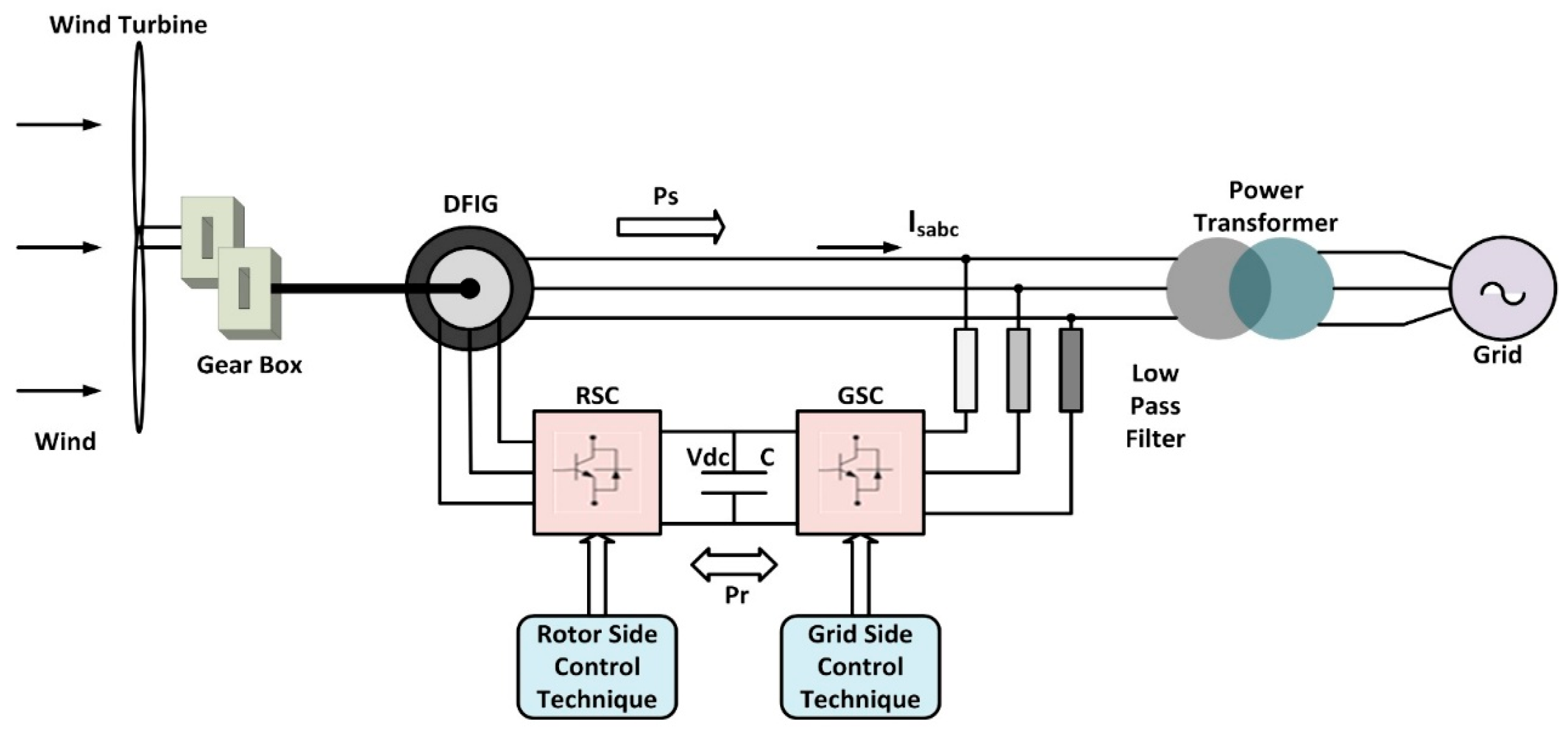
Figure 1. Components of DFIG-based WECS [29].
Machines 13 00687 g001
Figure 2. Model of DFIG-based WECS.
Machines 13 00687 g002
Figure 3. Equivalent circuit referring to stator.
Machines 13 00687 g003
Figure 4. (a,b) αβ-Equivalent Circuit diagram.
Machines 13 00687 g004
Figure 5. (a,b) DQ Equivalent circuit diagram [35].
Machines 13 00687 g005
Figure 6. Structural Diagram of SVR-Based Controller.
Machines 13 00687 g006
Figure 7. Flowchart of SVR Controller Implementation.
Machines 13 00687 g007
Figure 8. Enactment of SVR-based Controller in Rotor-Side Converter.
Machines 13 00687 g008
Figure 9. Implementation of the SVR-based controller in the grid-side converter.
Machines 13 00687 g009
Figure 10. A test input was introduced into the proposed simulation model.
Machines 13 00687 g010
Figure 11. SVR-Predicted Output vs. Actual Output for GSC after 20 s.
Machines 13 00687 g011
Figure 12. SVR-Predicted Output vs. Actual Output for RSC after 20 s.
Machines 13 00687 g012
Figure 13. Conventional PI and Proposed SVR Controller responses for rotor speed.
Machines 13 00687 g013
Figure 14. Conventional PI and Proposed SVR Controller responses for torque.
Machines 13 00687 g014
Figure 15. Conventional PI and Proposed SVR Controller responses for active power.
Machines 13 00687 g015
Figure 16. Conventional PI, and Proposed Controller responses for DC-Link Voltage.
Machines 13 00687 g016
Table 1. Comparative analysis of various controllers for optimizing wind energy in DFIG.
Serial NumberRef.Control Technique ImplementedParameters UsedInput SignalAdvantagesLimitationsTraining Required
1.[1,2,3,4,5]PI controllerRotor current, stator voltageVariable wind speedSimple design, effective for steady-state conditions, easy implementationFixed tuning, poor adaptability, degraded performance under nonlinear dynamicsNo
2.[6,7,8]2DOF PI controllerRotor current, stator voltageVariable wind speedImproves disturbance rejection, reduces overshootStill static in tuning, limited flexibility under highly dynamic gridsNo
3.[9]PI + FuzzyRotor current, stator voltageVariable wind speedBetter power quality, handles uncertainties betterMore complex design, needs fuzzy tuningNo
4.[10]ANN-based PI controllerRotor current, stator voltageVariable wind speedAdapts dynamically, better for real-time controlHigher computational needs, training requiredYes
5.[11,12,13]Fuzzy logic controllers (FLCs)Stator voltage, reactive powerVariable wind conditionsHandles nonlinearities, no precise model needed, enhances stabilityComplex design, requires expert rules, sensitive to membership designNo
6.[14,15,16]Artificial neural networks (ANNs)Active/reactive power, torqueGrid variationsLearns system dynamics, adapts to changes, accurate controlNeeds large training dataset, risk of overfitting, black-box behaviorYes
7.[17,18]Hybrid ANFIS-PI controllerRSC and GSC parametersWind speed variationCombines ANN and FLC, better controls accuracy, improves response timeHigh computational cost, complex tuning, long trainingYes
8.[19,20]Extreme learning machine (ELM)Rotor flux, stator voltageGrid disturbancesFast training speed, simple architectureSensitive to the number of hidden neuronsYes
9.[21,22]Random forest (RF)Fault diagnosis parametersGrid faultsHigh accuracy for classification tasksLarge memory requirements, limited real-time controlYes
10.[23,24]Reinforcement learning (RL)Frequency, active/reactive power controlVariable wind and loadSelf-learning capability, real-time adaptabilityLong exploration time, high training costYes
11.[25]LSTMMSE or MAE for regressionTime-series data (e.g., wind speed)Handles temporal patterns, strong prediction capabilityHigh training cost, large data requirement, not suited for real-time controlYes
12.[26]XGBoostUsually “reg:squarederror” for regressionStatic featuresHigh accuracy, fast convergenceNot suitable for dynamic control loops, no temporal memoryYes
13.[27]SVRKernel, C, ε, support vectorsWind speed,
temperature,
historical power output
Accurate wind power forecasting; robust to noisy inputs; generalizes well with limited data; suitable for nonlinear regression problemsNot designed for real-time control; requires preprocessed historical dataYes
14.ProposedSVR-based controllerRSC and GSC control parametersStep wind speed change (10.0 m/s to 12.0 m/s)Achieves a 17.2% decrease in rotor speed overshoot and enhances settling time by 30.2%, while maintaining low computational costEffectiveness depends on appropriate tuning of SVR parameters like kernel function and penalty valuesYes
Table 2. DFIG Electrical Machine Parameters [41].
Serial NumberSymbolParameter
1. V d s ,   V q s ,   V d r   and   V q r Stator, rotor voltages of dq axis
2. i d s ,   i q s ,   i d r ,   and   i q r Stator, rotor currents of dq axis
3. R r Rotor resistance
4. R s Stator resistance
5. ω s   and   ω r Stator and rotor angular velocities
6. ψ s ,   ψ r Stator and rotor magnetic flux linkages
7. ψ d s ,   ψ q s dq axes stator flux components
8. ψ d r ,   ψ q r dq axes rotor flux components
9. L s ,   L r Stator and rotor windings leakage inductance
10. L m Mutual inductance
11.pPole pairs
12. P s   and   Q s Stator active and reactive power
13. P r   and   Q r Rotor active and reactive power
14. T e Electromagnetic torque
15. J Rotor’s inertia
16. T l o a d Load torque
17. ω m Rotor speed
18. C f Friction coefficient
19.JRotor inertia
20. T m Mechanical torque
21.xState vector
22.yYield vector
Table 3. Generator specifications and rated parameters.
Serial NumberSymbolParameterValue and Unit
1. P Rated Power1.56 MVA
2. L Inductance0.312 pu
3. V d c DC Voltage1.154 KV
4. f Frequency50 Hz
5. V Rated L-L Voltage575.5 V
6. R Resistance0.00323 pu
Table 4. Parameters Configured in SVR model.
Serial NumberParametersValue
1.Kernel FunctionGaussian (RBF)
2.Kernel Scale (σ)1
3.Regularization Parameter (C)10 (Tuned via Grid Search)
4.Epsilon-insensitive Zone (ε)0.01(Tuned via Grid Search)
5.Dataset (Input–Output Pairs)400,001
6.Test Input (V Wind) at 10 sFrom 10.0 m/s to 12.0 m/s
7.No. of Inputs1
8.No. of Outputs1
9.Number of Support Vectors42,977
10.Training AlgorithmSVR
Table 5. Performance Evaluation after Simulation using SVR Controller in GSC.
Serial NumberParametersValue
1.MSE0.0067
2.RMSE0.082
3.MAE0.079
4.R20.8
Table 6. Performance Evaluation after Simulation using SVR Controller in RSC.
Serial NumberParametersValue
1.MSE0.008
2.RMSE0.089
3.MAE0.089
4.R20.71
Table 7. Statistical Analysis of SVR Controller Performance.
Serial NumberParametersMeanSD95% Confidence Interval (±)
1.Rotor Speed Overshoot (%)0.00.12±0.04
2.Torque Overshoot (%)1.00.20±0.07
3.Settling Time (s)2.10.25±0.09
4.DC-link Voltage Error (V)00.18±0.06
Table 8. Conventional and Intelligent Controllers’ Response Across Parameters.
Serial NumberParameterControl SchemeRise Time (s)Overshoot (%)Settling Time (s)Steady-State Error
1.Rotor SpeedWith PI2.56.56.00.002
With SVR1.401.80
2.TorqueWith PI2.296.00.004
With SVR1.412.00
3.Active PowerWith PI2.0146.50.003
With SVR1.412.50
4.DC Bus VoltageWith PI2.56.58.55
With SVR1.512.50
Disclaimer/Publisher’s Note: The statements, opinions and data contained in all publications are solely those of the individual author(s) and contributor(s) and not of MDPI and/or the editor(s). MDPI and/or the editor(s) disclaim responsibility for any injury to people or property resulting from any ideas, methods, instructions or products referred to in the content.