Article

Nose-Wheel Steering Control via Digital Twin and Multi-Disciplinary Co-Simulation

1
Shanghai Aircraft Design and Research Institute, Jinke Road No.5188, Pudong New District, Shanghai 201210, China
2
School of Mechanical and Electrical Engineering, Harbin Institute of Technology, Harbin 201109, China
*
Author to whom correspondence should be addressed.
Machines 2025, 13(8), 677; https://doi.org/10.3390/machines13080677 (registering DOI)
Submission received: 13 June 2025 / Revised: 29 July 2025 / Accepted: 30 July 2025 / Published: 1 August 2025
(This article belongs to the Section Robotics, Mechatronics and Intelligent Machines)

Abstract

The aircraft nose-wheel steering system serves as a critical component for ensuring ground taxiing safety and maneuvering efficiency. However, its dynamic control stability faces significant challenges under complex operational conditions. Existing research predominantly focuses on single-discipline modeling, with insufficient in-depth analysis of the coupling effects between hydraulic system dynamics and mechanical dynamics. Traditional PID controllers exhibit limitations in scenarios involving nonlinear time-varying conditions caused by normal load fluctuations of the landing gear buffer strut during high-speed landing phases, including increased control overshoot and inadequate adaptability to abrupt load variations. These issues severely compromise the stability of high-speed deviation correction and overall aircraft safety. To address these challenges, this study constructs a digital twin model based on real aircraft data and innovatively implements multidisciplinary co-simulation via Simcenter 3D, AMESim 2021.1, and MATLAB R2020a. A fuzzy adaptive PID controller is specifically designed to achieve adaptive adjustment of control parameters. Comparative analysis through co-simulation demonstrates that the proposed mechanical–electrical–hydraulic collaborative control strategy significantly reduces response delay, effectively minimizes control overshoot, and decreases hydraulic pressure-fluctuation amplitude by over 85.2%. This work provides a novel methodology for optimizing steering stability under nonlinear interference scenarios, offering substantial engineering applicability and promotion value.

1. Introduction

Runway safety remains a core challenge in aircraft ground operations within modern civil aviation. According to the International Air Transport Association (ATA) Safety Report, 22% of global aviation accidents from 2010 to 2014 were attributed to runway excursions. This trend has persisted in recent years—statistics from the Aviation Safety Network (ASN) indicate that among 720 global aviation accidents between 2017 and 2022, runway excursion/overrun/veer-off incidents accounted for 16.25% (117 cases) [1]. Dynamical analyses reveal that when an aircraft’s taxiing speed exceeds 80 knots (148 km/h), the centroid displacement induced by lateral velocity increments grows quadratically. In such scenarios, if the steering system’s response delay surpasses 500 ms, the risk of runway deviation surges by 57% [2]. This fundamentally establishes the engineering significance of precise nose-wheel steering control under high-dynamic conditions.
Meanwhile, aircraft ground taxiing, as a critical phase of flight operations, encompasses procedures from gate-to-runway takeoff and post-landing return. Its operational accuracy directly impacts flight scheduling efficiency, takeoff/landing safety, and taxiing security. This process demands not only precise large-angle steering control (e.g., ±60° under low-speed conditions, per ICAO Annex 14 standards), but also stable lateral dynamic characteristics at medium-to-high speeds (40–80 knots, ≈74–148 km/h). As the core actuator during ground taxiing, the dynamic stability of the nose-wheel steering system directly determines operational safety, airframe structural longevity, and passenger comfort. Consequently, research on precise steering control under multi-dynamic conditions holds substantial engineering value.
Accurate design of nose-wheel steering control laws relies on high-fidelity ground dynamic models to ensure effective yaw and lateral position control in complex ground environments [3] However, traditional modeling methods lack fidelity under dynamic loads, nonlinear friction, and multi-physics coupling, failing to meet high-robustness control requirements. Digital twin technology [4], with its lifecycle interaction capability between physical entities and virtual models, offers a novel approach to overcoming these limitations. In recent years, this technology has achieved scalable applications in aviation [5,6], including safety architecture design [7], engine health management [8], and wing aerodynamic optimization [9]. Nevertheless, its application in aircraft ground dynamics modeling and landing gear system research remains underexplored. First, high-fidelity modeling of tire–runway contact mechanics heavily depends on real-time environmental parameter sensing [10] (e.g., pavement friction coefficients, dynamic tire pressure variations) and data assimilation. Existing studies predominantly adopt offline calibration or simplified contact models [11] (e.g., constant friction assumptions), inadequately capturing the nonlinear coupling effects of transient lateral forces and yaw moments during taxiing. Second, the strong coupling between landing gear multibody dynamics and hydraulic steering systems has yet to be rigorously validated within a digital twin framework, hindering precise resistance to mechanical hysteresis, hydraulic pulsation, and ground disturbance in control law design [12]. Fundamentally, current digital twin research suffers from “insufficient characterization of multidisciplinary coupling mechanisms” and “lack of real-time virtual–physical interaction” in civil aircraft ground dynamics, impeding closed-loop optimization of control stability. This necessitates novel methodologies integrating cross-disciplinary modeling and real-time control.
Notably, extensive international research has focused on aircraft steering control during ground taxiing. As early as the mid-20th century, with the rise of jet airliners such as the Boeing 707 and Douglas DC-8, mechanically driven hydraulic-actuated nose-wheel steering systems saw widespread development. By the 1970s, European military aircraft had fully adopted fly-by-wire hydraulic steering systems. Young [13] documented the development process of advanced nose-wheel steering systems for commercial aircraft, including the integration of electronic controls and redundant systems. The United States also achieved early mastery of nose-wheel steering technology, with widespread applications across multiple aircraft models [14]. In contrast, China began emphasizing fully electric nose-wheel steering systems in the early 1980s [15]. Researchers such as Qing Nie at Nanjing University of Aeronautics and Astronautics pioneered the analysis of foreign steering mechanisms and designed a dual-worm-gear steering system with corresponding control strategies [16].
Current domestic research on the dynamic stability of nose-wheel steering systems remains inadequate. PID control strategies based on linear time-invariant systems, reliant on fixed parameters, struggle to achieve adaptive control [17]. This leads to poor stability under landing-phase load fluctuations and varying runway conditions, increasing runway excursion risks. To address this, this study introduces real aircraft parameters, pioneering the integration of hydraulic systems, mechanical dynamics, and fly-by-wire control modules. Through millisecond-level co-simulation, a digital twin with both precision and real-time capability is constructed (physical-to-virtual mapping). A fuzzy adaptive control algorithm is designed to establish bidirectional virtual–physical closed loops: the virtual model continuously reflects physical system states while inversely optimizing control parameters and fault prediction thresholds online (virtual-to-physical assistance). This approach enhances steering stability and accuracy under complex operational conditions.

2. Materials and Methods

2.1. Ground Taxiing Dynamics Modeling Based on Digital Twin

The civil aircraft nose-wheel steering system (NWS) investigated in this study adopts a gear-rack-type steer-by-wire (SBW) architecture, where the control logic is implemented by a steering electronic control unit (ECU), with the aircraft hydraulic system serving as the power source. The operational mechanism is structured as follows: a control valve regulates hydraulic fluid flow into the left/right chambers of the gear actuator cylinder, driving the piston and rack to generate axial displacement. The rack–gear meshing pair converts this linear motion into circumferential rotation of the gear, thereby inducing rotational motion of the rotating sleeve about its axis. Finally, the lugs on the rotating sleeve transmit the driving force to the wheel via the torque arm, completing the steering action.

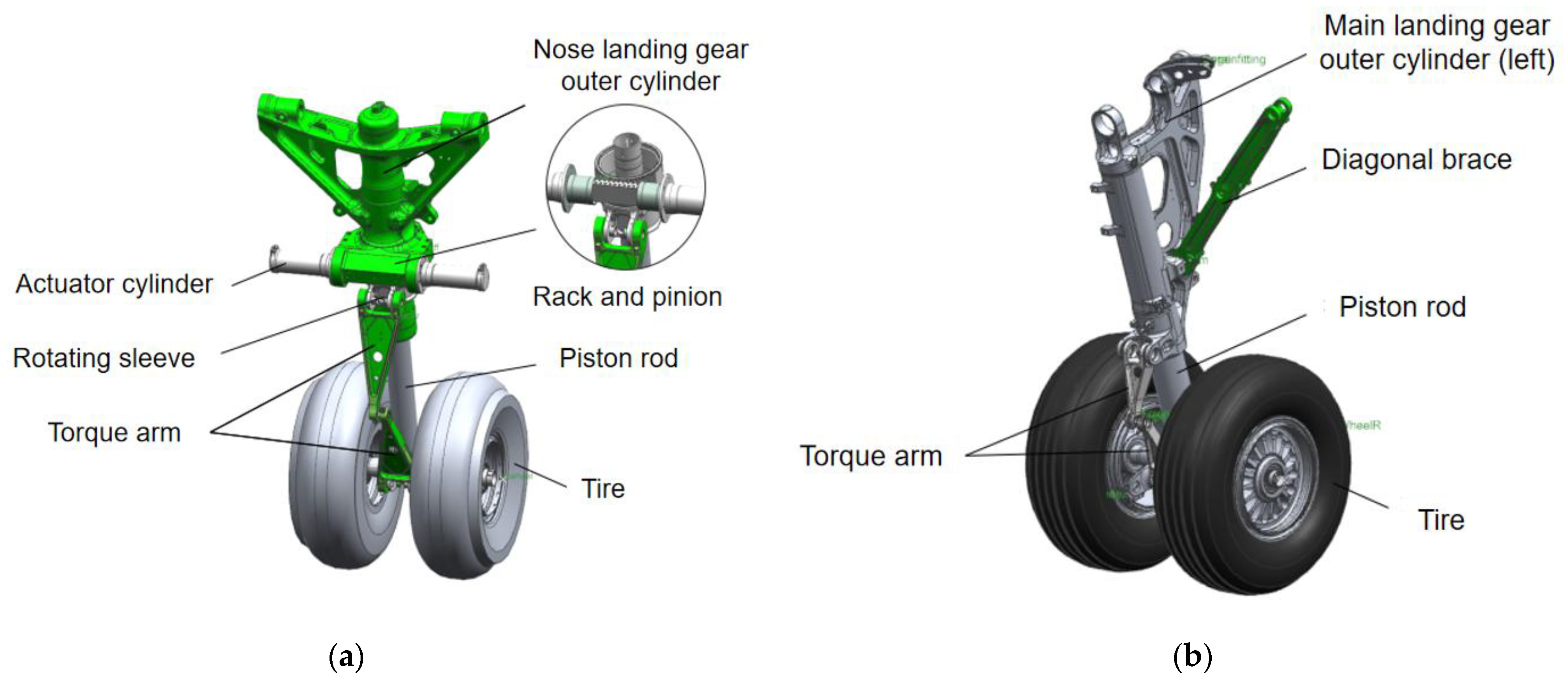
2.1.1. Landing Gear Model Simplification

This study focuses on a domestic aircraft model, specifically addressing the steering mechanism of its gear-rack-type nose-wheel steering system [18], A multi-body dynamics model is developed using Simcenter 3D Motion.
To ensure computational efficiency while retaining critical physical principles and emphasizing the dynamic coupling between nose-wheel steering and fuselage motion, the following simplifications are applied without compromising simulation precision:
  • Component simplification of landing gear: secondary components with negligible impact on steering—such as bolts, nuts, washers, and other fasteners—are omitted;
  • Rigid-body assumption: all landing gear components (excluding tires) and associated structures are treated as rigid bodies, disregarding material elastic deformation and structural vibrations [19];
  • Aerodynamic force exclusion: aerodynamic forces (lift, drag) acting on the nose-wheel during taxiing are neglected to avoid unnecessary higher-order nonlinear complexities.
Post-simplification, only components relevant to nose-wheel steering motion are retained. CATIA files of critical parts (e.g., strut outer cylinder, actuator cylinder, rotating sleeve) are imported into the Simcenter 3D module to assemble a simplified landing-gear geometric model. Material properties are defined, kinematic pairs are added, and force elements are integrated to establish the dynamics model, as illustrated in Figure 1.

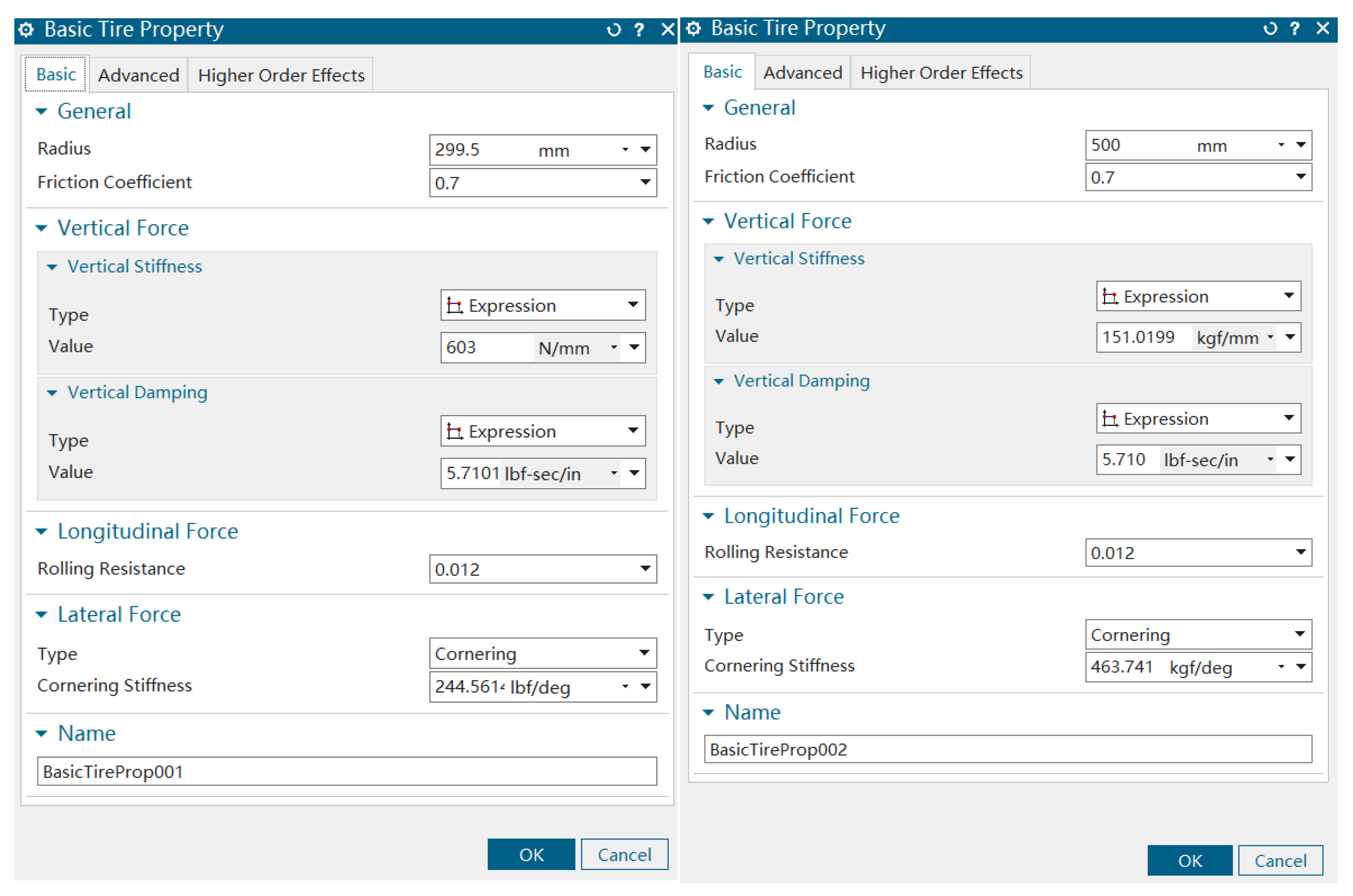
2.1.2. Tire Mechanical Model

The tire model is a critical component of the overall aircraft model. The six force and moment components acting on a tire are interdependent, which complicates the analysis and modeling of tire characteristics. The international standard for tire data exchange (TYDEX), established in 1977, standardized the coordinate systems and the definitions of tire motion, forces, and moments for converting tire data from test rigs to simulation models. The standard coordinate system adopted for the simulation is the ISO-W tire contact patch coordinate system [20], as illustrated in Figure 2.
The external loads experienced by the aircraft during a turn primarily originate from the friction between the tires and the ground. This friction can be decomposed into longitudinal and lateral components. The friction moment for the nose-wheel turn is generated exclusively by the lateral friction force [21]. To accurately simulate the forces exerted by the ground on the tire during a nose-wheel turn, a suitable tire model must be established. This study utilizes the tire model available in Simcenter 3D Motion, wherein the calculation of the tire’s lateral force is divided into two distinct phases: an elastic deformation phase and a sliding phase. A critical slip angle is defined within the model to distinguish between these two states. In the elastic phase, the lateral force is a function of the normal force and the slip angle, which can be determined by a cubic polynomial defined by the following boundary conditions:
F y = 0   ,   α   = 0     F y = F y m a x     ,   α = α n   d F y d α = C , α = 0 d F y d α n = 0 , α = α n
where
F y is the lateral force on the tire.
α is the tire slip angle.
C is the derivative of the lateral force with respect to the slip angle when the slip angle is zero (i.e., the cornering stiffness).
α n is the critical slip angle.
When the slip angle is small, the lateral force on the tire can be considered a linear function of the slip angle:
F y = C α
When the tire slip angle exceeds the critical slip angle, the lateral force reaches its maximum value:
α n = 2.5 F n o r C
F y m a x = μ F n o r
where
F n o r is the normal force on the tire.
μ is the nominal friction coefficient.

2.1.3. Tire Subsystem

The tire subsystem established in this study employs the basic tire model from Simcenter 3D Motion. The specific formulas for the forces and moments in this model were detailed in the previous section. The tire model is defined by inputting the wheel radius, relaxation length, wheel cornering stiffness, vertical stiffness, and damping coefficient into the tire subsystem creation interface. The tire’s static load-deflection curve is then provided in the tire properties file to complete the definition. Based on a review of the relevant literature, the tire parameters were obtained as shown in Figure 3, where BasicTireProp001 corresponds to the nose landing-gear tire parameters and BasicTireProp002 corresponds to the main landing-gear tire parameters.

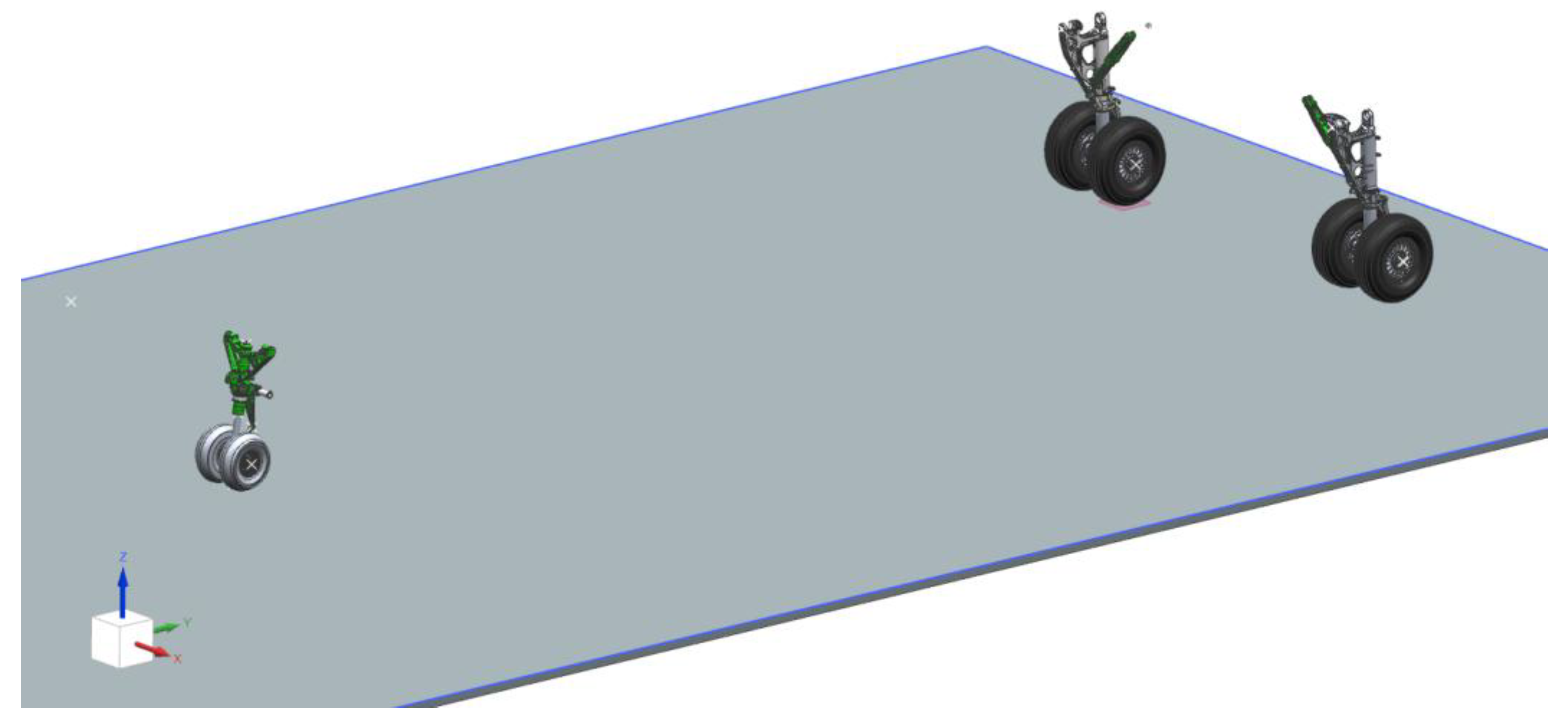
2.1.4. Full-Aircraft Virtual Model Construction

Upon completion of the landing gear model, it is integrated with the airframe, tire dynamics model, and damper subsystem. To balance simulation efficiency and inertial characteristics, the airframe model is reconstructed and simplified using the principle of inertial equivalence: the mass, center of gravity, and inertia tensor of the fuselage are mapped to an equivalent geometric body (a cube), whose center of gravity aligns with that of the actual airframe. This simplified geometry is solely used for dynamic computation, and does not affect boundary condition definitions in aerodynamic/structural coupling scenarios. The finalized full-aircraft dynamics model is illustrated in Figure 4.
In addition to the constraint relationships between internal landing gear components described in Section 2.1.1, the force and kinematic relationships between the airframe and other components are shown in Figure 5, where B denotes components, J represents kinematic pairs between components, and F indicates forces and moments. Connection points are defined on the local coordinate system of the airframe (equivalent cube) to distribute the aircraft’s weight through rigid connections between the landing gear and these points. The aircraft is assumed to exhibit motion only in the horizontal plane (translational movement and rotation about the vertical axis), ignoring roll, pitch, and other degrees of freedom, thereby modeling it as a three-degree-of-freedom (3-DOF) system during ground motion.

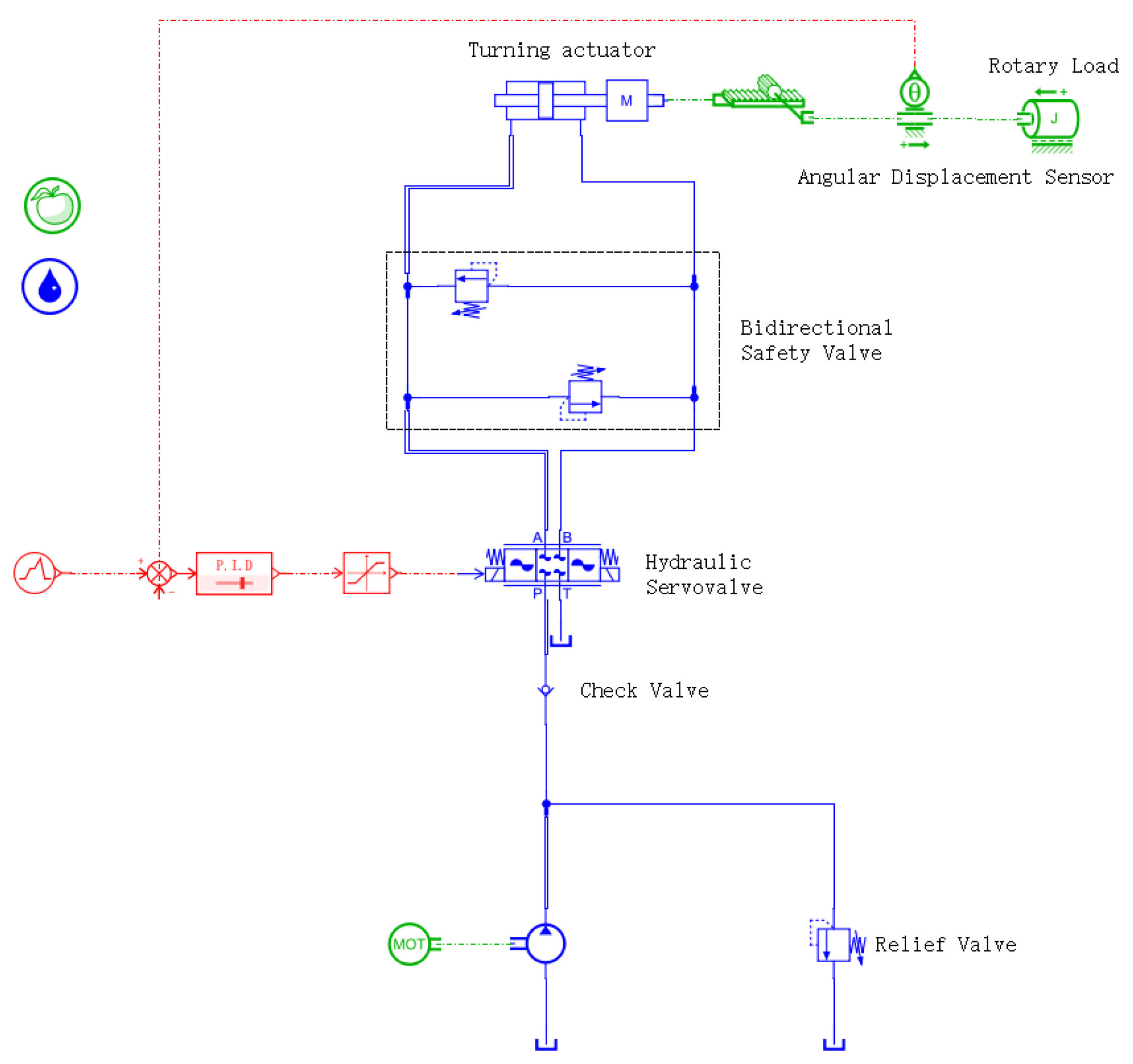
2.2. Physical Modeling of Nose-Wheel Electro-Hydraulic Servo Steering System

The nose-wheel steering system employed in this study is an electro-hydraulic servo system, with its hydraulic schematic illustrated in Figure 6. This hydraulic system comprises an electro-hydraulic servo valve, steering actuator cylinder, anti-shimmy valve, and safety valve [22].
When the pilot issues a steering command, the steering control module dynamically compares the input command value with feedback signals. Upon detecting a deviation between predefined parameters and real-time feedback values that exceeds the preset tolerance threshold, the system automatically generates deviation control signals. These signals adjust the orifice opening and direction of the electro-hydraulic servo valve, altering the hydraulic fluid flow path. This adjustment induces corresponding spool displacement, which drives the steering actuator piston to execute linear reciprocating motion. Subsequently, the mechanical transmission system (gear-rack mechanism) transfers this motion to rotate the nose landing-gear wheel assembly. Simultaneously, the steering angle of the nose landing gear is fed back in real time to the steering control module. Based on the closed-loop control principle, this feedback signal and the input command jointly determine the spool position of the electro-hydraulic servo valve. This adjustment continues until the actual steering angle converges within the predefined allowable error range relative to the commanded value, thereby achieving precise follow-up control performance.
When steering is unnecessary or the system fails to execute steering commands, the nose-wheel steering system switches to anti-shimmy mode to ensure operational safety and taxiing stability. In this mode, the hydraulic circuits of the two actuator cylinders are interconnected, allowing hydraulic fluid to circulate between them via two anti-shimmy valves. If external disturbances cause the nose-wheel to deviate from its intended trajectory, the anti-shimmy valves absorb and dissipate vibration energy through their inherent damping characteristics. Concurrently, the stabilizing moment generated by the nose-wheel geometry restores the wheel to its centered position.
This hydraulic subsystem model is constructed using the hydraulic component design library and drivetrain system library in AMESim, as illustrated in Figure 7.

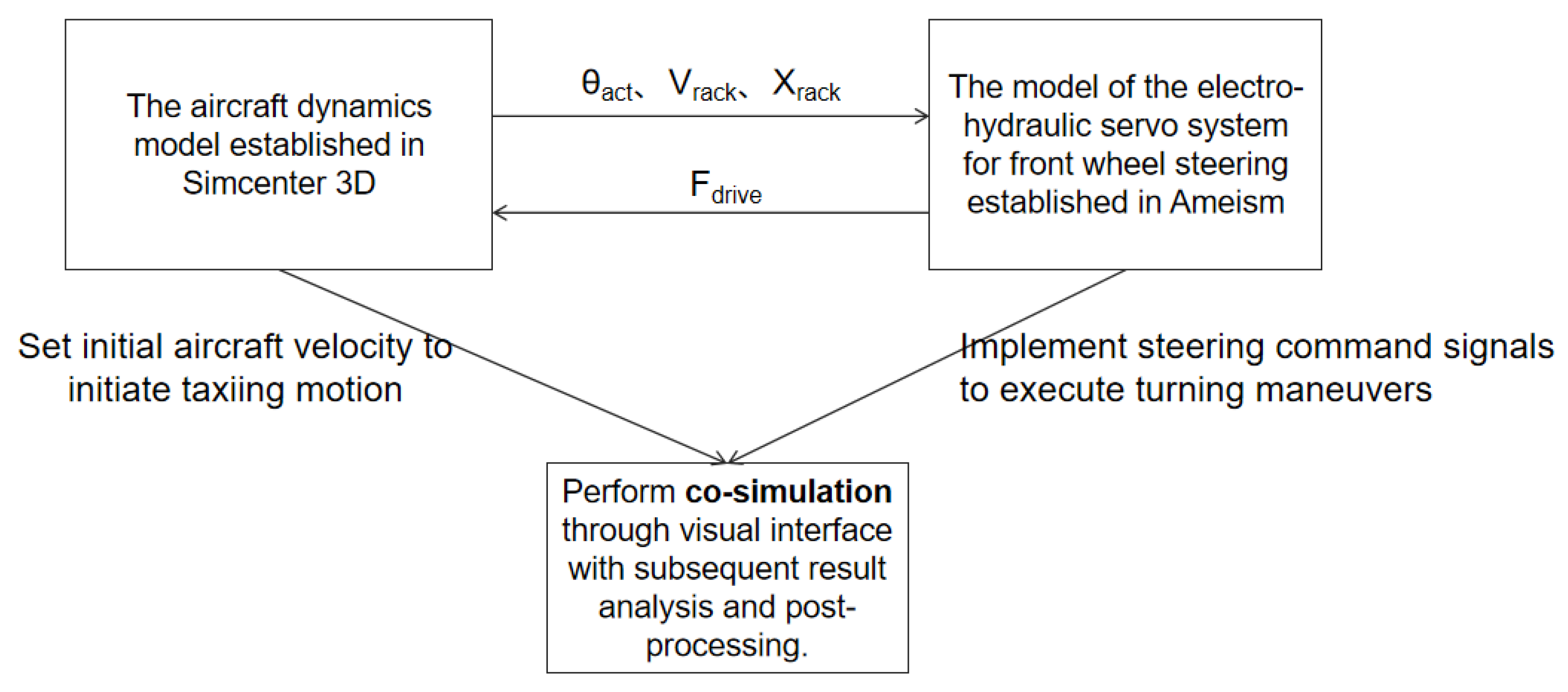
2.3. Multidisciplinary Co-Simulation

Research on aircraft ground taxiing dynamics requires the integration of dynamic interactions among mechanical, hydraulic, and control systems. This chapter establishes a high-fidelity multidisciplinary coupled model within a co-simulation environment combining Simcenter 3D Motion and AMESim. The model encompasses fly-by-wire controller command logic, flow–pressure characteristics of hydraulic actuators, nonlinear contact in gear-rack transmission, and wheel–ground slip dynamics.
To enable physical interactions between subsystems, a bidirectional coupling interface is constructed based on the Functional Mock-up Interface (FMI) protocol, facilitating mechanical–hydraulic energy exchange and state variable synchronization between Simcenter 3D and AMESim. During co-simulation, the preconfigured steering drive module in the Simcenter 3D dynamics model is replaced with a dedicated “Mechatronics” co-simulation module. Within this module, three control-input state variables (nose-wheel steering angle, rack velocity, and rack displacement) and one control-output state variable (driving force) are defined. The control inputs represent data exported from the multibody dynamics model, while the control output corresponds to the driving force transmitted from the AMESim hydraulic system to the dynamics model.
The AMESim co-simulation interface is automatically generated through a standardized workflow: after defining input/output variables with names identical to those in Simcenter 3D, the interface type is selected as “Simcenter 3D Motion (co-simulation),” which automatically synchronizes with Simcenter’s co-simulation settings.
Figure 8 illustrates the multidisciplinary co-simulation framework for aircraft ground taxiing steering. During co-simulation, the electro–hydraulic servo control system implemented in AMESim generates control signals based on target steering commands. The hydraulic subsystem, upon receiving these current signals, produces actuator driving forces according to the servo valve’s flow–pressure characteristics. These forces are transmitted via the interface to the gear-rack assembly in the Simcenter 3D dynamics model. Within the dynamics model, the driving force on the rack induces circumferential motion of the gear, thereby actuating the nose-wheel steering mechanism to produce the actual steering angle. Simultaneously, real-time rack displacement and velocity parameters are fed back through the interface to the hydraulic control loop, forming a closed-loop dynamic compensation mechanism. The validity of the co-simulation system is confirmed by observing synchronized mechanical–hydraulic variations via a visualization interface.

2.4. Design of Fuzzy Adaptive PID Controller

Based on the nose-wheel steering-system model architecture described in Chapter 2.1, the control module employs a PID control algorithm to dynamically compute deviations between input command values and real-time feedback of the actual steering angle. When the deviation between real-time feedback and command parameters exceeds a predefined threshold, the system activates a compensation control-signal generation mechanism: by adjusting the opening direction and flow area of the electro-hydraulic servo valve, the hydraulic fluid distribution in the actuator chambers is modified, thereby precisely regulating piston rod displacement until the actual steering angle converges within the allowable error band of the command. This achieves closed-loop follow-up control of steering angle versus displacement.
While this baseline control architecture demonstrates satisfactory precision under steady-state conditions, its fixed-gain characteristics exhibit theoretical limitations in adapting to complex dynamic scenarios. Particularly during high-speed taxiing deviation correction, traditional PID control suffers from instability issues such as increased overshoot and response lag, due to coupling effects like nonlinear load distribution on the nose gear and time-varying tire cornering stiffness [23]. To address this, a fuzzy adaptive PID controller integrating traditional PID control with fuzzy logic inference is proposed. This controller overcomes the inherent parameter constraints of conventional PID by dynamically adjusting control parameters through online identification of system nonlinearity. Compared to fixed-parameter PID controllers, this method offers three core advantages:
  • Dynamic parameter self-tuning capability: real-time adjustment of control parameters based on error signals, resolving traditional PID’s inability to adapt to complex disturbances such as time-varying runway–tire friction and nonlinear hysteresis in hydraulic systems;
  • Enhanced robustness and anti-windup properties: suppression of integral windup via fuzzy rules, preventing control instability caused by actuator output saturation under extreme conditions; in conventional PID control, anti-windup functionality typically requires an additional independent module (e.g., integrator clamping or back-calculation). However, in our proposed fuzzy adaptive controller, anti-windup capability is embedded directly within the fuzzy inference rules, demonstrating greater design integration and functional advancement.
  • Multi-objective collaborative optimization: balancing overshoot suppression with response speed, addressing the inherent conflict between steady-state accuracy and dynamic performance in traditional PID tuning.
Leveraging these advantages, this study develops a dual-input (steering angle deviation e, deviation rate ec)—triple-output (∆Kp, ∆Ki, ∆Kd) fuzzy rule base. The design rationale lies in utilizing e to characterize steady-state precision requirements and ec to capture dynamic process characteristics. Their synergistic integration enables coverage of multi-timescale response features during high-speed landing correction phases, including load transfer and hydraulic hysteresis. This rule base dynamically adjusts PID parameters [24] (proportional coefficient Kp, integral coefficient Ki, derivative coefficient Kd), thereby optimizing system control and enhancing steering stability under extreme operating conditions.
Regarding the use of additional feedback signals, the control strategy is constrained by the existing hardware configuration of the nose-wheel steering system. The system is equipped only with a steering angle sensor for closed-loop control and pressure sensors for monitoring, as depicted in the hydraulic schematic (Figure 6). This hardware suite does not support more complex multi-state feedback strategies that would require additional measurements like actuator velocity or hydraulic flow rates. Therefore, the proposed control law is designed to maximize performance using the available feedback, adhering to the engineering principle of employing the minimum necessary sensor set to ensure robustness, reliability, and cost-effectiveness. The potential for performance enhancement through an expanded sensor suite remains a valuable direction for future system iterations.

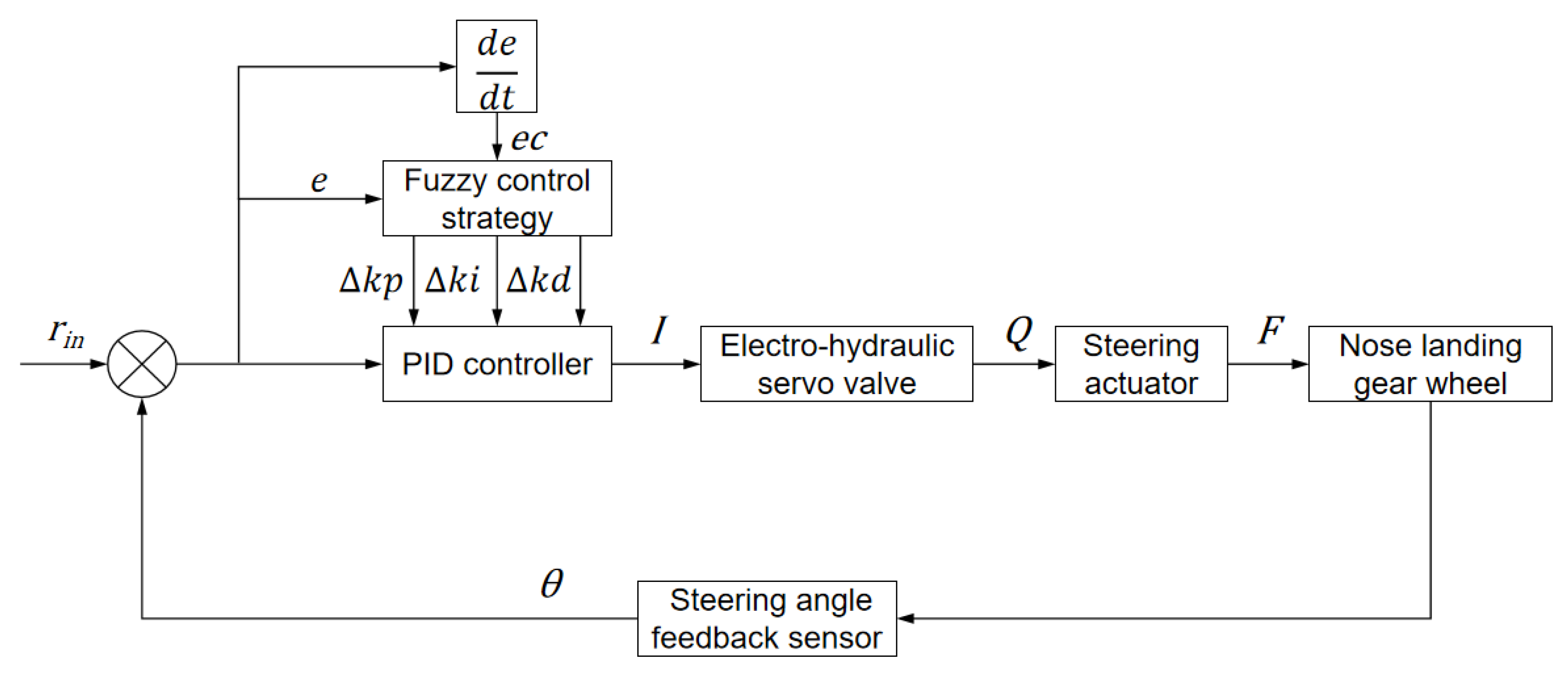
2.4.1. Fuzzy Controller Architecture Design

As illustrated in the structural diagram of the fuzzy adaptive PID controller in Figure 9, the input variables are defined as the steering angle deviation e and the steering angle deviation rate ec, where
e = r i n θ
e c = d e / d t
Here, r i n represents the commanded steering angle, and θ denotes the real-time steering angle.
The output variables correspond to the adjustment quantities for the PID controller parameters: ∆Kp (adjustment to the proportional coefficient Kp), ∆Ki (adjustment to the integral coefficient Ki) and ∆Kd (adjustment to the derivative coefficient Kd).

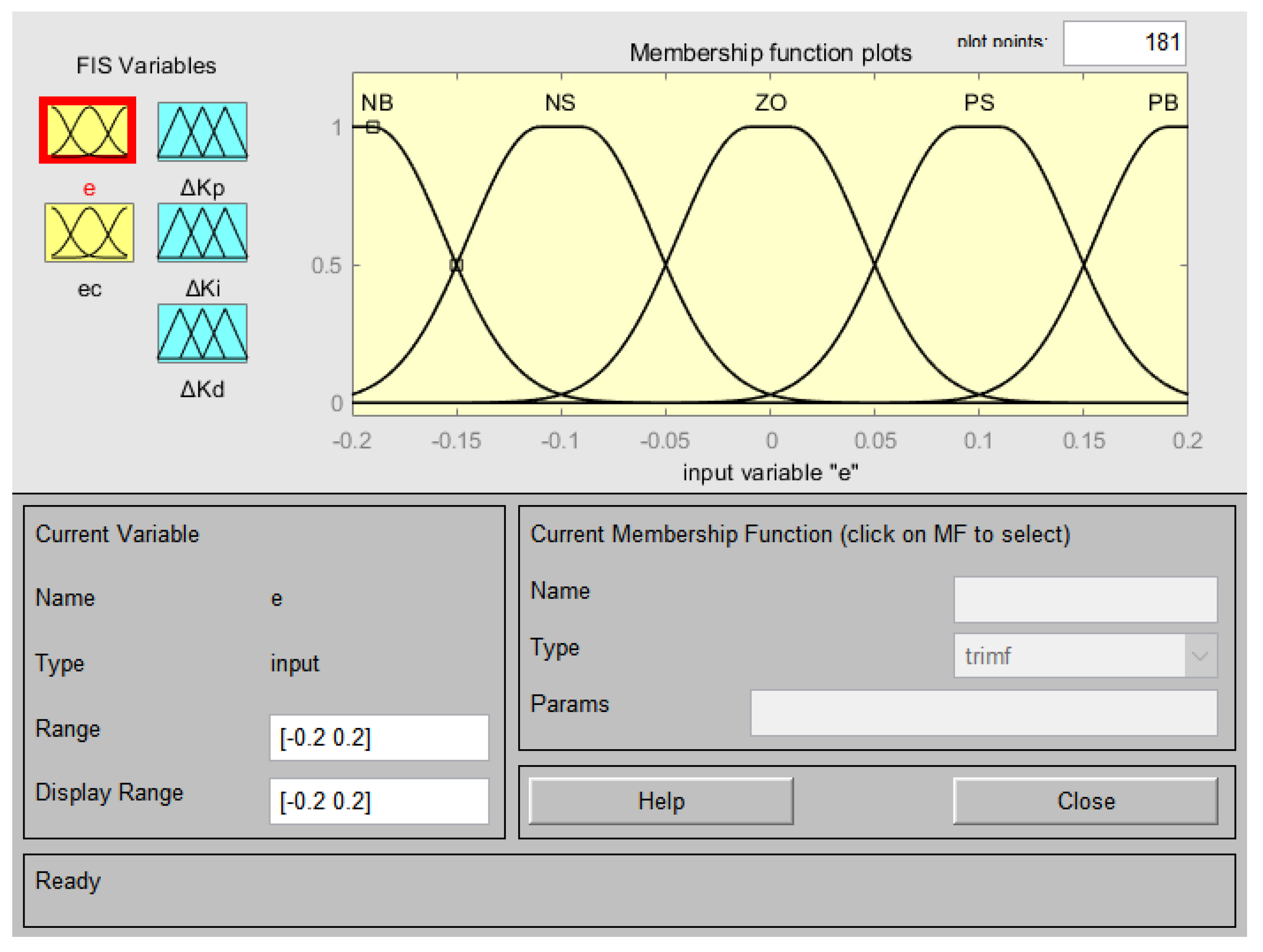
2.4.2. Design of Linguistic Variables and Membership Functions

Based on fuzzy control rules [25], the variables e, ec, ΔKp, ∆Ki, and ∆Kd are fuzzified into five linguistic subsets: NB (Negative Big), NS (Negative Small), ZO (Zero), PS (Positive Small), and PB (Positive Big). To better approximate real-world conditions, the universes of discourse for e and ec are defined in radians as [−0.2, 0.2] and [−0.1, 0.1], respectively. Gaussian functions are adopted as membership functions, as illustrated in Figure 10. For consistency, the remaining variables employ identical membership functions with optimized universes of discourse.

2.4.3. Fuzzy Controller Rule-Base Formulation

Drawing upon the operational characteristics of the selected aircraft model and domain expertise, a fuzzy rule base comprising 25 IF-THEN rules (derived from 5 × 5 input combinations) was formulated to define the input–output mapping relationships, as detailed in Table 1.
Rule Design Logic:
  • Large Negative Deviation with Stabilizing Trend (e = NB, ec = ZO): significantly increase Kp (ΔKp = PB) to enhance rapid response to substantial deviations; moderately reduce Ki(∆Ki = NS) to prevent integral windup caused by persistent deviations; maintain Kd (∆Kd = ZO) unchanged, as the zero deviation rate minimizes derivative influence;
  • Zero Deviation with Gradual Positive Increase (e = ZO, ec = PS): slightly decrease Kp (ΔKp = NS) to avoid overshoot from excessive response; moderately increase Ki (∆Ki = PS) to eliminate residual steady-state errors; enhance Kd (∆Kd = PS) to preemptively suppress oscillations induced by rising deviation rates;
  • Large Positive Deviation with Rapid Reduction (e = PB, ec = NB): maximize Kp (ΔKp = PB) to expedite residual error elimination; disable Ki (∆Ki = NB) to prevent overshoot from cumulative integral action during late-stage correction; sharply increase Kd (∆Kd = PB) to counteract oscillations arising from rapid convergence;
  • Anti-Windup Mechanism (e = PB/NB): when system error e is large, the mechanism outputs a negative integral gain adjustment (∆Ki = NB), effectively reducing or temporarily disabling the integral action. This prevents unlimited accumulation of the integral term, achieving anti-windup functionality.
By accessing the view options in MATLAB R2020a’s Fuzzy Editor window, users can activate the 2D rule viewer and 3D surface viewer to examine the relationships between input and output variables. As shown in the 3D observation plot in Figure 11, this approach ensures full coverage of the input space and eliminates rule conflicts. Figure 12 shows the dynamic variation curves of Kp, Ki, and Kd during the step-response simulation.

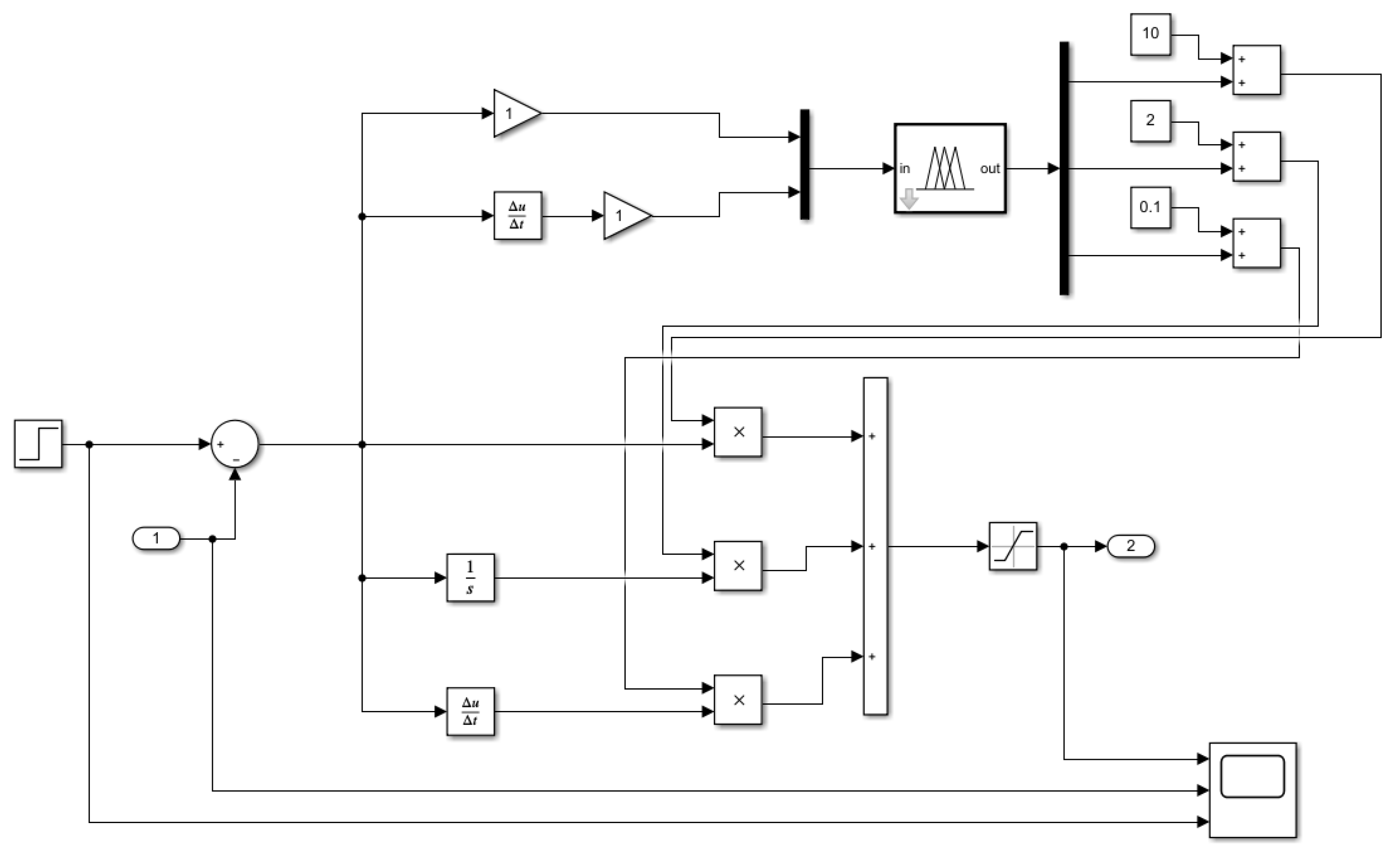
2.4.4. Encapsulation of the Fuzzy Controller

As illustrated in Figure 13, an adaptive PID controller based on the fuzzy rule base is constructed in Simulink. To validate its engineering applicability, this controller is integrated into the Simcenter-Amesim co-simulation platform, replacing the original PID controller in the hydraulic system.
This section utilizes the MATLAB/Simulink-Amesim bidirectional interface protocol and the “sl2amecosim” tool to compile the Simulink model into an AMESim-compatible Super Component (Figure 14). The interface is defined as follows: Input Port 1 receives the real-time nose-wheel steering angle signal (unit: deg) from the dynamics model; output Port 2 transmits the valve control current signal u-valve (unit: mA) to the hydraulic servo system. The electric control signal output at Port 2 is shown in Figure 15. This encapsulation method decouples the control algorithm from the hydraulic model through the Functional Mock-up Interface (FMI) standard, while its modular architecture provides an extensible technical framework for subsequent co-simulation studies.

3. Results

3.1. Analysis of Co-Simulation Results for Nose-Wheel Steering System

Simulation experiments are conducted under defined initial conditions to quantify key performance metrics such as steering angle error and response time. A comparative analysis between the traditional PID controller and the proposed fuzzy adaptive controller is performed to validate robustness advantages.

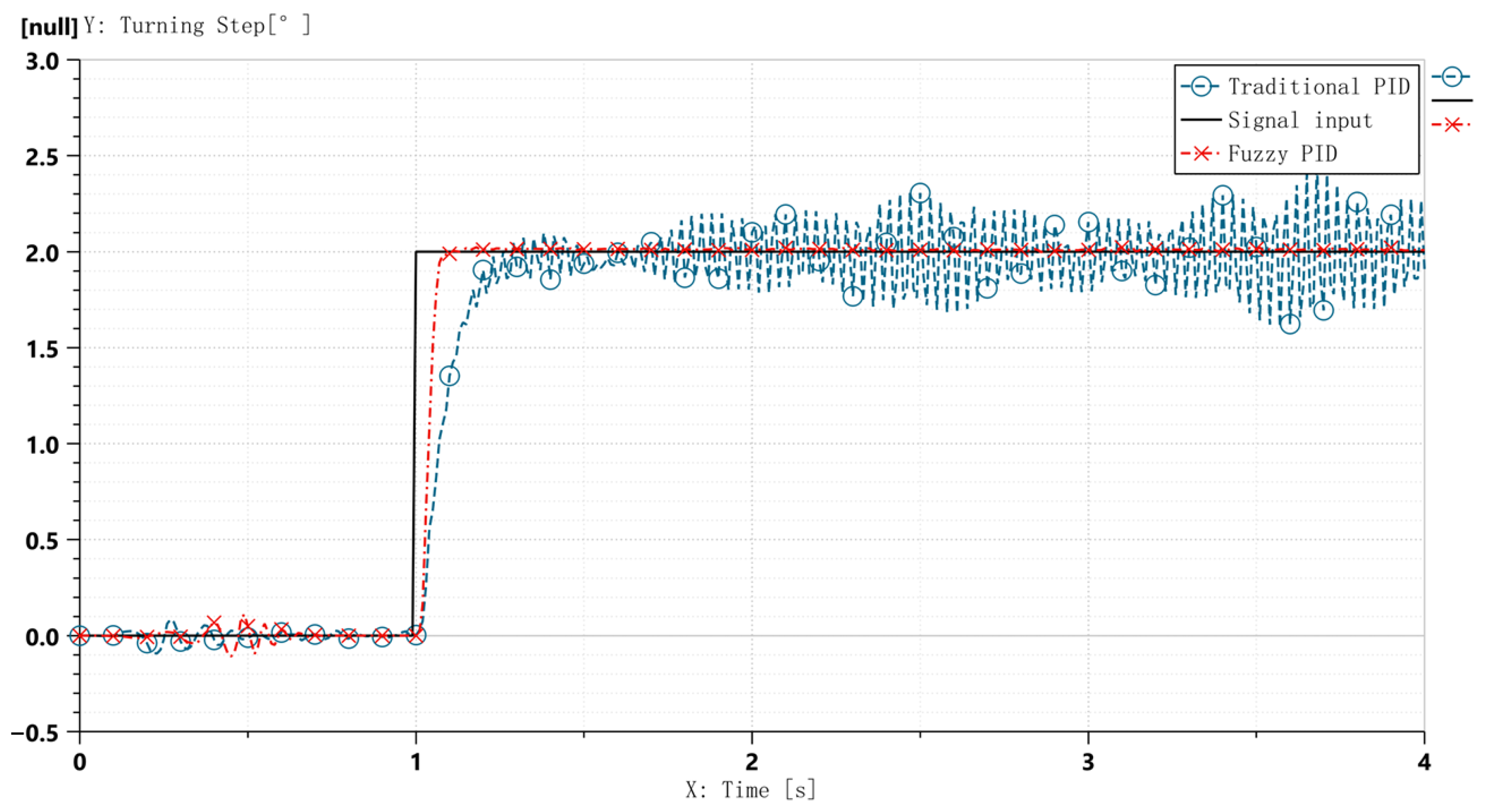
3.1.1. Step Control During High-Speed Landing

The simulation scenario assumes an aircraft forward speed of 140 knots (≈72 m/s) at a height of 0.5 m (immediately before touchdown), with the nose-wheel initially centered. At t = 1 s, a steering command is issued to drive the nose-wheel toward the maximum steering angle θ1 = 2°, with the aim of achieving rapid response and quick stabilization. A step input signal is applied, and the control loop operates at a sampling time of 0.1 s. The resultant nose-wheel force characteristics are observed, as shown in Figure 16. Comparative simulation results between the two control strategies are illustrated in Figure 17.
The simulation encompasses two distinct phases. First, the landing impact phase (t < 1 s), where a stepwise surge in the normal load on the nose landing gear (Figure 16b) induces mechanical oscillations. Second, the steering command phase (t ≥ 1 s), where the control system must execute a 2° step command while the system is still settling from the initial impact.
Comparative curves in Figure 17 demonstrate that the proposed fuzzy adaptive PID controller outperforms the traditional PID controller under high-speed taxiing-step steering conditions: system fluctuations are significantly suppressed, with settling time reduced to 0.1 s, meeting the CCAR-25-R4 (China Civil Aviation Regulations, Part 25) requirement for steering system stabilization time (≤0.5 s); hydraulic actuator pressure variation curves in Figure 18 validate the control strategy’s efficacy. The left chamber’s hydraulic response transitions from sustained oscillations between 65 and 92 bar to rapid convergence at 70 ± 2 bar, with fluctuation amplitude reduced by 85.2%. This effectively mitigates hydraulic resonance risks under high-speed step conditions.
Additionally, during 0.5 s ≤ t ≤ 1 s, the hydraulic pressure under fuzzy PID control exhibits higher fluctuations than conventional PID, while the steering angle response remains more stable. This phenomenon occurs because at landing touchdown (t < 1 s), the normal force on the nose-wheel increases abruptly (Figure 16b). This sudden load change acts as a disturbance to the hydraulic system, inducing pressure oscillations.
The fuzzy adaptive PID controller, being highly sensitive to both error e and error rate ec, immediately performs fine adjustments to precisely maintain the wheel at the neutral position. This proactive disturbance suppression activates the hydraulic system minimally, resulting in slight pressure elevation. In contrast, the conventional PID controller responds passively with lower sensitivity, allowing pressure to oscillate freely until significant error accumulates, thereby exhibiting weaker hydraulic response.

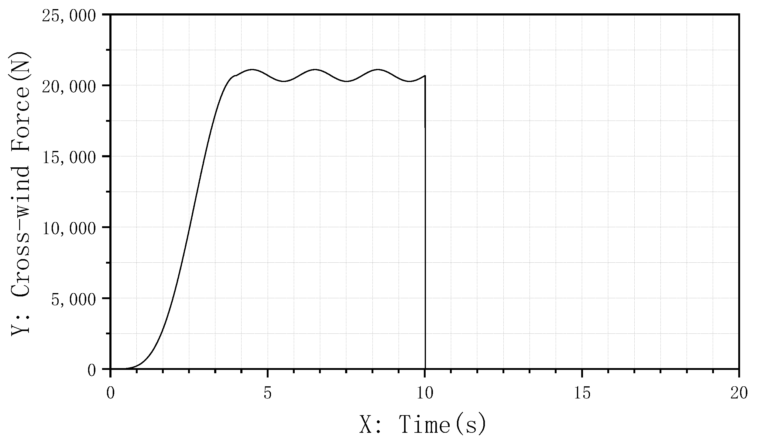
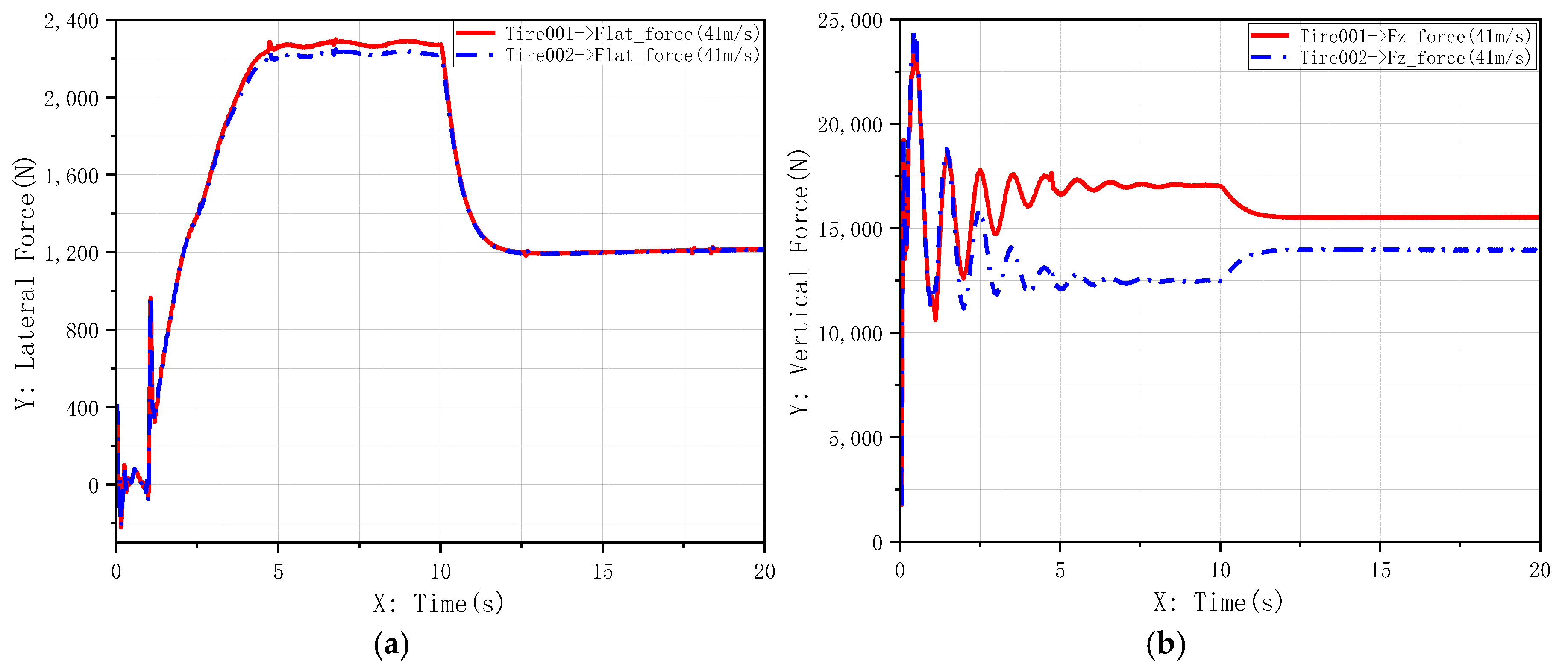
3.1.2. Robustness Analysis Under Crosswind Disturbance

To comprehensively evaluate controller performance under external physical disturbances, this study introduces lateral crosswind interference during medium-speed taxiing. The disturbance is modeled using the “1-cosine” crosswind profile specified in MIL-F-8785C Military Specification [26], which effectively simulates discrete, severe wind events. Assuming minor fluctuations in wind speed, the crosswind velocity is designed as
V w i n d = 0 , t < 0 V m 2 1 c o s ( π t t m ) , 0 t t m V m 1 + s i n ( π ( t t m ) ) 100 , t > t m
where V w i n d denotes crosswind velocity, V m represents crosswind magnitude, t m a indicates peak disturbance time, and t defines wind duration. The lateral force Z 1 acting on the aircraft is calculated via Equation (8):
Z 1 = ρ S w C Y V w i n d 2
where ρ is air density, S w is wing area, and C Y is lateral force coefficient. The key parameters used in this simulation are shown in Table 2.
The simulation scenario is configured as follows: the aircraft taxies straight at 80 kt (approximately 41.1 m/s). At t = 0 s, crosswind disturbance is applied. The crosswind intensity increases smoothly to a peak of 15 m/s over 4 s and maintains this intensity thereafter, with the total disturbance lasting 10 s. This process simulates the aircraft encountering progressive strong crosswinds during taxiing. Figure 19 illustrates the variation curve of the applied crosswind force.
Under crosswind interference, the force dynamics on the nose-wheel during medium-speed taxiing are observed in Figure 20. Comparative simulation results for different controllers are shown in Figure 21 and Figure 22.
The co-simulation results clearly demonstrate the superior robustness of the fuzzy adaptive PID controller:
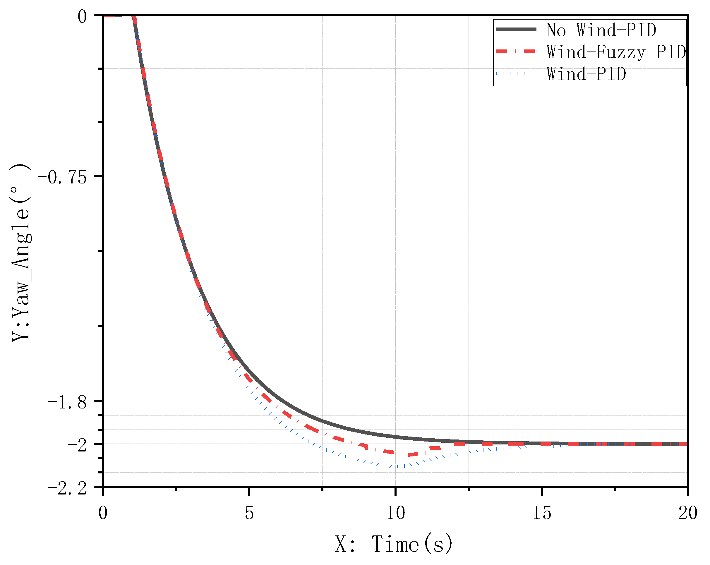
  • Heading Maintenance (Figure 21): after crosswind impact, the aircraft with conventional PID control exhibited a maximum yaw deviation exceeding 0.12° and required extended time to fully suppress the yaw; in contrast, the fuzzy adaptive PID controller rapidly adjusted its gains to actively suppress disturbances, limiting maximum lateral deviation to within 0.05° and achieving swift stabilization;
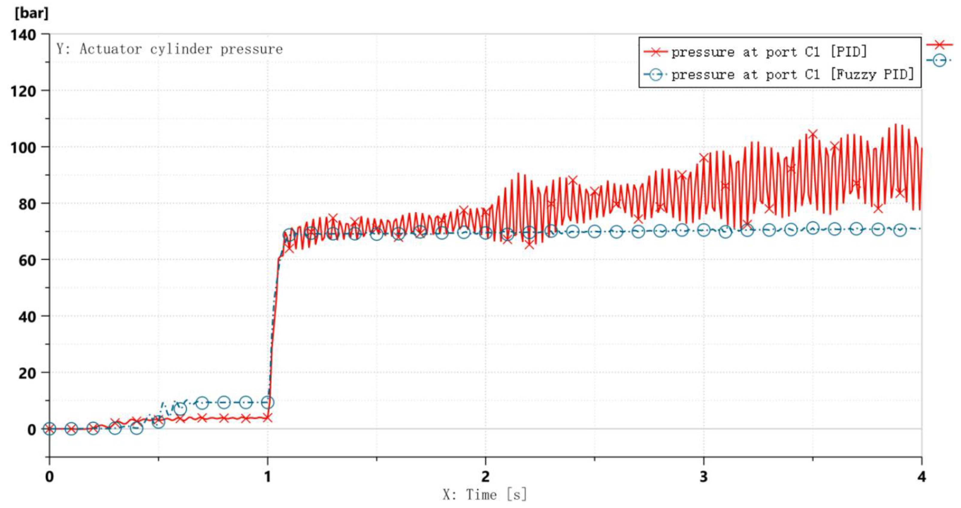
  • Hydraulic System Stability (Figure 22): under external crosswind disturbance, the hydraulic pressure of the conventional PID controller showed sustained oscillations, increasing the risk of component fatigue and failure; the pressure response of the fuzzy adaptive PID controller remained significantly smoother, reaffirming its advantage in suppressing hydraulic fluctuations.

4. Conclusions

  • Addressing the bottleneck of traditional single-discipline modeling in simulating mechanical–hydraulic-control coupling effects, this study innovatively adopts a high-fidelity co-simulation architecture integrating multidisciplinary tools. By leveraging the strengths of Simcenter 3D (mechanical dynamics), AMESim (hydraulic systems), and MATLAB/Simulink (control algorithms), a digital twin with both precision and real-time capability is constructed through millisecond-level data interaction. This framework provides an authentic simulation environment for subsequent research on steering control laws.
  • To resolve the control stability challenges caused by fixed PID parameters under nonlinear conditions, a novel fuzzy adaptive control strategy is proposed. By dynamically optimizing PID parameters (K_p, K_i, K_d) through online fuzzy rule-based tuning, this method overcomes the poor adaptability of conventional steering control strategies in nonlinear scenarios. It offers a solution to stability degradation caused by unstable nose-wheel loads during landing phases, thereby enhancing deviation correction capability and landing safety.
  • Comparative simulation analyses demonstrate that the proposed control strategy achieves superior performance over traditional PID methods, including accelerated system response, significantly reduced overshoot, and over 85.2% suppression of hydraulic pressure fluctuations.
In summary, the proposed fuzzy adaptive PID control method effectively mitigates runway deviation risks by addressing control inaccuracies and instabilities induced by abrupt load changes and nonlinear time-varying factors. Integrating real-time parameter adaptation with a multidisciplinary co-simulation verification framework, this methodology exhibits strong universality and can be extended to the design and performance analysis of steering systems across aircraft models, providing a reference for precise and rapid steering system engineering.

Author Contributions

Conceptualization, W.C. and L.Z.; methodology, W.C.; software, L.Z.; validation, W.C. and L.Z.; formal analysis, W.C.; investigation, L.Z.; resources, W.C.; data curation, Z.T.; writing—original draft preparation, L.Z.; writing—review and editing, W.C. and L.Z.; visualization, L.L.; supervision, Z.T.; project administration, L.L.; funding acquisition, L.L. All authors have read and agreed to the published version of the manuscript.

Funding

This research received no external funding.

Data Availability Statement

For privacy reasons, it is not possible to disclose additional data.

Conflicts of Interest

The authors declare no conflicts of interest.

References

  1. Chen, W.; Chen, Y.; Xu, Y.; Jiang, Y. Study on the Test and Adjustment Method of Civil Aircraft Taxiing Deviation. Aerospace 2024, 11, 732. [Google Scholar] [CrossRef]
  2. Davis, P.A.; Stubbs, S.M.; Tanner, J.A. Langley Aircraft Landing Dynamics Facility; NASA Reference Publication: Washington, DC, USA, 1987.
  3. Dai, Y.; Song, J.; Yu, L.; Lu, Z.; Zheng, S.; Li, F. The lateral control during aircraft-on-ground deceleration phases. Aerosp. Sci. Technol. 2019, 95, 105482. [Google Scholar] [CrossRef]
  4. Tao, F.; Xiao, B.; Qi, Q.; Cheng, J.; Ji, P. Digital twin modeling. J. Manuf. Syst. 2022, 64, 372–389. [Google Scholar] [CrossRef]
  5. Li, L.; Aslam, S.; Wileman, A.J.; Perinpanayagam, S. Digital Twin in Aerospace Industry: A Gentle Introduction. IEEE Access 2022, 10, 9543–9562. [Google Scholar] [CrossRef]
  6. Yin, Z.H.; Wang, L. Application and Development Prospect of Digital Twin Technology in Aerospace. In Proceedings of the 3rd IFAC Workshop pn Cyber-Physical and Human Systems (CPHS), Beijing, China, 3–5 December 2020. [Google Scholar]
  7. Kabashkin, I. Digital Twin Framework for Aircraft Lifecycle Management Based on Data-Driven Models. Mathematics 2024, 12, 2979. [Google Scholar] [CrossRef]
  8. Wu, Z.; Li, J. A Framework of Dynamic Data Driven Digital Twin for Complex Engineering Products: The Example of Aircraft Engine Health Management. In Proceedings of the 30th International Conference on Flexible Automation and Intelligent Manufacturing (FAIM), Athens, Greece, 15–18 June 2021. [Google Scholar]
  9. Zhou, H.; Xie, F.; Ji, T.; Zhang, X.; Zheng, C.; Zheng, Y. Fast transonic flow prediction enables efficient aerodynamic design. Phys. Fluids 2023, 35, 026109. [Google Scholar] [CrossRef]
  10. Dong, Q.; Wang, J.; Zhang, X.; Wang, H.; Zhao, J. Dynamic response analysis of airport pavements during aircraft taxiing for evaluating pavement bearing capacity. J. Zhejiang Univ. Sci. A 2021, 22, 736–750. [Google Scholar] [CrossRef]
  11. Shi, X.; Cai, L.; Wang, G.; Liang, L. A New Aircraft Taxiing Model Based on Filtering White Noise Method. IEEE Access 2020, 8, 10070–10087. [Google Scholar] [CrossRef]
  12. Shan, D.; Gu, X.; Huang, Q.; Gu, X.; Lan, Y. A Digital-Twin Assisted Simulation for the Electromechanical System of Aircraft. In Proceedings of the Asia-Pacific International Symposium on Aerospace Technology (APISAT), Lingshui, China, 16–18 October 2023. [Google Scholar]
  13. Young, D.W.S.; Ohly, B. European Aircraft Steering Systems; SAE International: Warrendale, PA, USA, 1985. [Google Scholar]
  14. Sadien, E.; Roos, C.; Birouche, A.; Carton, M.; Grimault, C.; Romana, L.-E.; Basset, M. A simple and efficient control allocation scheme for on-ground aircraft runway centerline tracking. Control Eng. Pract. 2020, 95, 104228. [Google Scholar] [CrossRef]
  15. Wang, D.; Hemming, S.; Yang, Y.; Poorfakhraei, A.; Zhou, L.; Liu, C.; Emadi, A. Multilevel Inverters for Electric Aircraft Applications: Current Status and Future Trends. IEEE Trans. Transp. Electrif. 2024, 10, 3258–3282. [Google Scholar] [CrossRef]
  16. Nie, Q.; Nie, H.; Zhang, M. Design and Dynamic Analysis of Dual Actuator Nose Wheel Steering System on Large Civil Aircraft. J. Nanjing Univ. Aeronaut. Astronaut. Nanjing Hangkong Hangtian Daxue Xuebao 2012, 44, 503–510. [Google Scholar]
  17. Wu, Z.; Peng, H.; Li, F.; Huang, T.; Yang, C.; Gui, W. Extended dissipative analysis and taxiing control of fuzzy model based aircraft-on-ground systems via sliding mode approach. J. Frankl. Inst. 2022, 359, 4623–4641. [Google Scholar] [CrossRef]
  18. Chang, Q.-C.; Xue, C.-J. Reliability Analysis and Experimental Verification of Landing-Gear Steering Mechanism Considering Environmental Temperature. J. Aircr. 2018, 55, 1154–1164. [Google Scholar] [CrossRef]
  19. Yin, Q.; Kong, D.; Song, J.; Wei, X.; Nie, H. Influence of asymmetrical factors on aircraft ground steering stability. Aerosp. Sci. Technol. 2023, 142, 108698. [Google Scholar] [CrossRef]
  20. He, H.; Wu, R.; Huang, W. Design of Aircraft Antiskid Brake System with ANN and FNN. Acta Aeronaut. Astronaut. Sin. 2005, 1, 116–120. [Google Scholar]
  21. Neto, M.M.; Sandoval Goes, L.C. Use of LMS Amesim® model and a bond graph support to predict behavior impacts of typical failures in an aircraft hydraulic brake system. J. Braz. Soc. Mech. Sci. Eng. 2018, 40, 414. [Google Scholar] [CrossRef]
  22. Li, D.; Lin, M.; Zhang, T. Design and co-simulation of a nose wheel steering system for a civil aircraft. Proc. Inst. Mech. Eng. Part G-J. Aerosp. Eng. 2022, 236, 1388–1395. [Google Scholar] [CrossRef]
  23. Soumya, N.; Jee, G.; Kavitha, C.S.; Nair, A.P.; Rajeev, U.P.; Padmakumar, E.S. Modelling and Lateral-Directional Control of a Winged Re-entry Vehicle on Runway. IFAC-Pap. 2022, 55, 504–509. [Google Scholar] [CrossRef]
  24. Petrov, M.; Ganchev, I.; Taneva, A. Fuzzy PID control of nonlinear plants. In Proceedings of the 1st International IEEE Symposium on Intelligent Systems, Varna, Bulgaria, 10–12 September 2002. [Google Scholar]
  25. Lee, B.-K.; Kim, I.-H.; Kim, J.-H. Stability Analysis and Proposal of a Simple Form of a Fuzzy PID Controller. J. Adv. Mar. Eng. Technol. 2004, 28, 1299–1312. [Google Scholar]
  26. Dogan, A.; Lewis, T.A.; Blake, W. Flight Data Analysis and Simulation of Wind Effects During Aerial Refueling. J. Aircr. 2008, 45, 2036–2048. [Google Scholar] [CrossRef]
Figure 1. Simplified landing-gear subsystem mode: (a) nose landing gear; (b) main landing gear.
Machines 13 00677 g001
Figure 2. ISO-W tire contact patch coordinate system.
Machines 13 00677 g002
Figure 3. Tire force parameters.
Machines 13 00677 g003
Figure 4. Full-aircraft dynamics model.
Machines 13 00677 g004
Figure 5. Dynamic relationship diagram of full-aircraft virtual prototype.
Machines 13 00677 g005
Figure 6. Hydraulic schematic diagram of nose-wheel steering system.
Machines 13 00677 g006
Figure 7. Nose-wheel steering system mode.
Machines 13 00677 g007
Figure 8. Block diagram of multidisciplinary co-simulation model for aircraft ground taxiing steering.
Machines 13 00677 g008
Figure 9. Structural diagram of model reference adaptive PID Controller.
Machines 13 00677 g009
Figure 10. Membership function of e (negative values are denoted with “-”).
Machines 13 00677 g010
Figure 11. Fuzzy rule 3D surface viewer (negative values are denoted with “-”).
Machines 13 00677 g011
Figure 12. Dynamic response of fuzzy PID controller parameters under step input.
Machines 13 00677 g012
Figure 13. Simulink architecture of fuzzy controller(negative values are denoted with “-”).
Machines 13 00677 g013
Figure 14. AMESim super-component encapsulation.
Machines 13 00677 g014
Figure 15. Control signal diagram of output port 2.
Machines 13 00677 g015
Figure 16. Variation curves of loads on aircraft nose landing gear: (a) Lateral load variation curve of nose wheel; (b) Vertical load variation curve of nose wheel.
Machines 13 00677 g016
Figure 17. Step-response curves: conventional PID vs. fuzzy PID control.
Machines 13 00677 g017
Figure 18. Hydraulic pressure variation curve of actuator cylinder left chamber.
Machines 13 00677 g018
Figure 19. “1-cosine” crosswind disturbance force variation curve.
Machines 13 00677 g019
Figure 20. Variation curves of loads on aircraft nose landing gear under crosswind interference: (a) Lateral load variation curve of nose wheel; (b) Vertical load variation curve of nose wheel.
Machines 13 00677 g020
Figure 21. Yaw angle response under crosswind disturbance: controller comparison.
Machines 13 00677 g021
Figure 22. Left-chamber pressure variation of actuator under crosswind disturbance.
Machines 13 00677 g022
Table 1. Fuzzy Rule Table.
PID Parameter e
NBNSZOPSPB
ecNBΔKp = PB,
ΔKi = NB,
ΔKd = NB
ΔKp = PB,
ΔKi = NB,
ΔKd = NS
ΔKp = PS,
ΔKi = NB,
ΔKd = NB
ΔKp = PS,
ΔKi = NB,
ΔKd = PB
ΔKp = PB,
ΔKi = NB,
ΔKd = PB
NSΔKp = PB,
ΔKi = NB,
ΔKd = NS
ΔKp = PS,
ΔKi = NB,
ΔKd = NS
ΔKp = PS,
ΔKi = NS,
ΔKd = NS
ΔKp = ZO,
ΔKi = NS,
ΔKd = PS
ΔKp = PB,
ΔKi = NB,
ΔKd = PS
ZOΔKp = PB,
ΔKi = NS,
ΔKd = ZO
ΔKp = PS,
ΔKi = NS,
ΔKd = ZO
ΔKp = ZO,
ΔKi = ZO,
ΔKd = ZO
ΔKp = NS,
ΔKi = ZO,
ΔKd = ZO
ΔKp = PB,
ΔKi = NS,
ΔKd = ZO
PSΔKp = PS,
ΔKi = ZO,
ΔKd = PS
ΔKp = ZO,
ΔKi = ZO,
ΔKd = PS
ΔKp = NS,
ΔKi = PS,
ΔKd = PS
ΔKp = NS,
ΔKi = PS,
ΔKd = NS
ΔKp = PS,
ΔKi = ZO,
ΔKd = NS
PBΔKp = PS,
ΔKi = PS,
ΔKd = PB
ΔKp = NS,
ΔKi = PS,
ΔKd = PB
ΔKp = NS,
ΔKi = PS,
ΔKd = PB
ΔKp = NB,
ΔKi = PB,
ΔKd = NB
ΔKp = PS,
ΔKi = PS,
ΔKd = PB
Table 2. Crosswind Disturbance Parameters.
ParametersValues
wind yaw angle90°
air   density ρ 1.225 Kg/m3
wing   area S w 79.86 m2
lateral   force   coefficient C Y 0.94
crosswind   magnitude V m 15 m/s
indicates   peak   disturbance   time t m 4 s
wind duration—t10 s
Disclaimer/Publisher’s Note: The statements, opinions and data contained in all publications are solely those of the individual author(s) and contributor(s) and not of MDPI and/or the editor(s). MDPI and/or the editor(s) disclaim responsibility for any injury to people or property resulting from any ideas, methods, instructions or products referred to in the content.

