1. Introduction
Electrical discharge machining (EDM) has long been established as a non-traditional machining process suitable for difficult-to-cut conductive materials. However, conventional EDM faces limitations such as low material removal rates (MRRs), poor surface quality, and inefficient debris evacuation in deep or complex geometries. Recently, an unsupervised learning pipeline combining dynamic time warping (DTW) and hierarchical clustering has been proposed to classify EDM discharge pulses without requiring predefined thresholds or labeled data, thus enabling adaptive and real-time process monitoring across varying machining conditions [
1]. These approaches improve the understanding of pulse dynamics and support the development of more stable and intelligent EDM processes.
To overcome these limitations, a broader research direction has focused on hybridizing EDM with other physical mechanisms to improve performance. While the present work investigates ultrasonic vibration assistance, other hybrid approaches—such as combining EDM with mechanical grinding or electrochemical discharge grinding using shaped abrasive tools—have also been explored to enhance the machining of difficult-to-machine materials like metal matrix composites. These hybrid strategies form part of a wider effort to extend EDM capabilities beyond its traditional limits.
Numerous studies have demonstrated that ultrasonic vibration-assisted EDM (UV-EDM) significantly improves machining efficiency, surface finish, and flushing capability, primarily by enhancing debris removal through the micro-agitation of the dielectric and by promoting more stable discharges via cavitation effects in the spark gap.
Wang et al. [
2] introduced longitudinal/torsional ultrasonic vibration in deep-hole EDM and reported the significant suppression of hole taper and improved debris evacuation. Similarly, Bui et al. [
3] applied ultrasonic vibration to enhance antibacterial surface generation in powder-mixed EDM using silver particles, showing enhanced surface functionality. Zhang et al. [
4] conducted a multi-objective optimization of UV-EDM for Ti6Al4V micro-holes, confirming its capability to enhance both MRR and surface integrity. Chen et al. [
5] further analyzed the effect of horizontal ultrasonic vibration on micro-hole machining and found improved discharge stability and reduced tool wear.
The use of longitudinal–torsional vibration was also explored by Yin et al. [
6], who developed an innovative electrode design to improve micro-hole machining efficiency. Dong et al. [
7] studied the mechanism of surface topography in powder-mixed UV-EDM and highlighted how vibration-induced cavitation and bubble collapse influenced the surface texture. In a similar vein, Sasaki et al. [
8] observed bubble behavior during UV-EDM, contributing to a better understanding of debris expulsion mechanisms.
Recent works have expanded UV-EDM to complex geometries and new electrode configurations. Lei et al. [
9] employed laminated electrodes to machine enclosed microgrooves, while Han et al. [
10] investigated the machining characteristics in the powder-mixed UV-EDM of TiN ceramics. Xing et al. [
11] examined micro-EDM under varying ultrasonic parameters, concluding that optimal amplitude and current significantly influence material removal and Ra.
Wang et al. [
12] and Wang et al. [
13] provided insight into the material removal and cavitation mechanisms in UV-EDM, suggesting that bubble implosion plays a critical role in enhancing localized erosion. Singh et al. [
14] evaluated the combined effect of ultrasonic vibration and rotating magnetic fields, while Choubey et al. [
15] employed finite element modeling to simulate MRR in UV-EDM and non-UV modes.
Hou and Bai [
16] proposed a novel 3D relative ultrasonic vibration (RTDUV) mechanism to improve debris removal, showing measurable gains in process stability. Dong et al. [
17] conducted thermodynamic simulations and validated experimentally the influence of vertical ultrasonic vibration on energy concentration and spark distribution. Multi-objective optimization frameworks have also been explored. Xu et al. [
18] optimized Ti6Al4V micro-EDM using NSGA-II, identifying trade-offs between machining efficiency and surface quality. Xing et al. [
19] applied UV-EDM milling for high aspect ratio microgrooves and demonstrated improved dimensional accuracy.
Advanced modeling approaches were adopted by Hou et al. [
20] to study material erosion using heat flow coupling analysis, while Xu et al. [
21] extended ultrasonic assistance to the hybrid milling–EDM of Ti6Al4V, improving tool life and reducing machining forces. Tang et al. [
22] addressed depth errors in microgrooves using circular ultrasonic electrodes, and Liu et al. [
23] integrated EDM with ultrasonic drilling for composite processing applications.
Ultrasonic-assisted EDM offers several key advantages, including more efficient debris removal and a cleaner spark gap, which together help stabilize the discharge process and increase the material removal rate (MRR) [
5,
9,
24]. Additionally, it results in smoother surfaces with fewer defects compared with conventional EDM, due to reduced uneven discharges and minimized surface burning [
5,
24]. These benefits make UV-EDM particularly attractive for improving both productivity and surface quality in EDM operations.
Although previous studies have demonstrated the significant advantages of ultrasonic vibration in EDM, most of them have focused on hole or micro-hole machining [
3,
6], deep-hole drilling [
2,
5], microgroove fabrication [
9,
19], or powder-mixed EDM configurations [
7,
10,
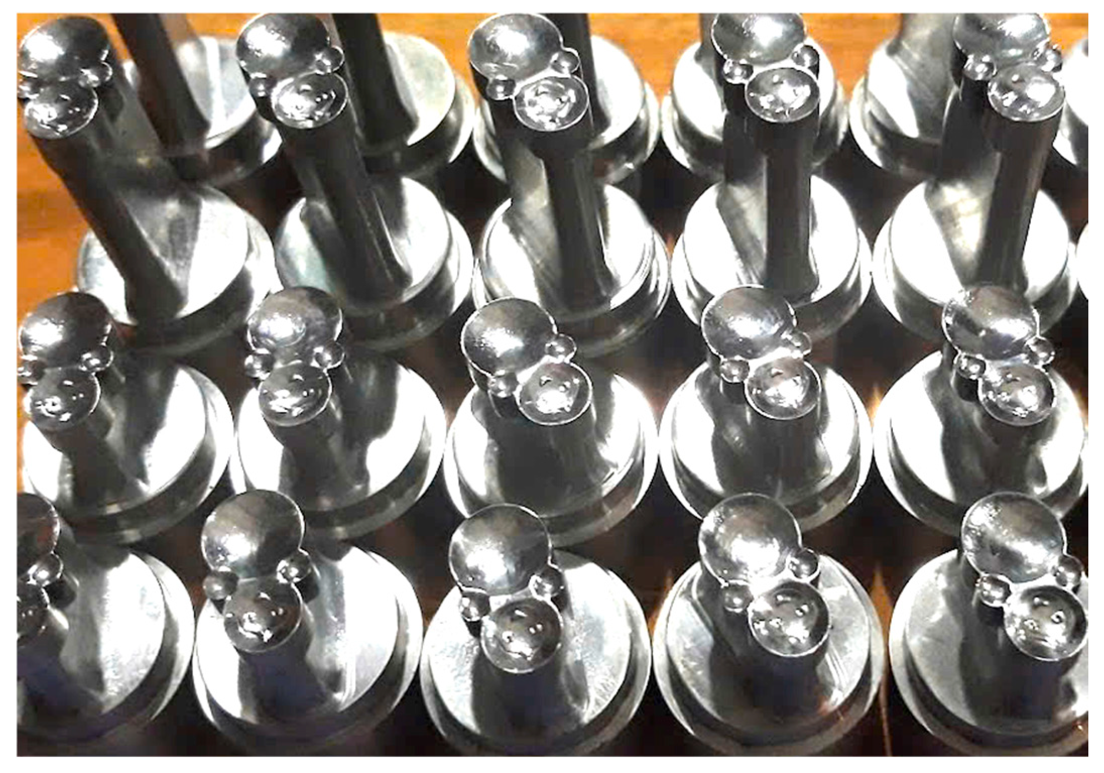
24]. Only recently has UV-EDM been applied to the machining of external cylindrical surfaces, as reported in [
25], which utilized copper electrodes. This type of surface is common in practical applications such as tablet punch tools (see
Figure 1) and metal-forming dies.
However, to the best of our knowledge, no prior study has investigated the ultrasonic EDM of external cylindrical surfaces using graphite electrodes. Graphite is particularly attractive for EDM due to its very high sublimation temperature (~3600 °C), which makes it highly resistant to wear under spark discharge conditions. Additionally, it offers a low density and excellent machinability, making it suitable for producing the complex-shaped electrodes required in industrial EDM processes.
To bridge this gap, this study presents the first investigation into the ultrasonic EDM of external cylindrical surfaces using graphite electrodes. A custom horn made from 90CrSi was designed to operate at 20 kHz resonance, ensuring effective energy transmission during machining. This study employs a Box–Behnken design to evaluate the influence of five input parameters—amplitude (A), Ton, Toff, Ip, and SV—on MRR and Ra. A hybrid optimization framework combining NSGA-II and AHP was developed, with the selection strategy prioritizing maximum MRR while maintaining Ra below 4 µm. The results demonstrate the viability of the proposed approach for high-performance cylindrical EDM applications, with potential impact in medical and precision tooling industries.
2. Horn Design for Ultrasonic EDM
2.1. Design Basis of the Horn
Ultrasonic vibration-assisted electrical discharge machining (UV-EDM) is an advanced development in conventional EDM technology, aiming to enhance material removal rate (MRR), improve surface finish (Ra), and stabilize the discharge process. Depending on the system configuration, ultrasonic vibration (UV) can be transmitted to the workpiece [
26], the tool electrode [
27,
28], or the dielectric fluid [
29]. Among these, applying vibration to the electrode is the most commonly used configuration due to its ease of implementation in standard EDM systems. However, this approach becomes unsuitable when using graphite electrodes, which are brittle and vulnerable to mechanical fracture under high-frequency excitation.
In addition to its brittleness, graphite also exhibits poor mechanical wave propagation compared with metals, which limits its effectiveness in transmitting ultrasonic vibration to the discharge zone. For this reason, in the present study, ultrasonic vibration is not applied to the electrode but instead transmitted to the workpiece via a custom-designed horn. This configuration avoids subjecting the graphite electrode to mechanical stress from vibration and ensures more effective energy transfer to the machining interface.
The design objective of the horn is to ensure the maximum vibration amplitude at the contact interface between the horn and the workpiece. This corresponds to the anti-node of a longitudinal standing wave propagating along the horn. To achieve this, the horn must be tuned to resonate at the operating frequency of 20 kHz, so that the interface coincides with a quarter-wavelength (λ/4) position from the vibration node (typically located at the transducer–horn interface).
The horn is fabricated from 90CrSi tool steel, chosen for its high Young’s modulus, thermal resistance, and efficient transmission of longitudinal waves. The horn geometry, including its stepped profile and section lengths, is initially determined through theoretical wave propagation models and subsequently fine-tuned through experimental validation. The unique choice of transmitting ultrasonic energy directly into the external cylindrical surface of the workpiece—rather than through the electrode as in prior studies [
27,
28]—constitutes one of the key technical contributions of this research. Compared with tool- or fluid-based vibration, this configuration introduces specific design challenges, such as ensuring effective mechanical coupling with a fixed or rotating cylindrical surface and minimizing vibration losses at the clamping interface. However, it also offers advantages, including a reduced risk of electrode damage (especially for brittle materials like graphite) and more uniform vibration transfer to the entire machined surface, potentially leading to improved discharge consistency and process stability.
2.2. Theoretical Calculation of Horn Length
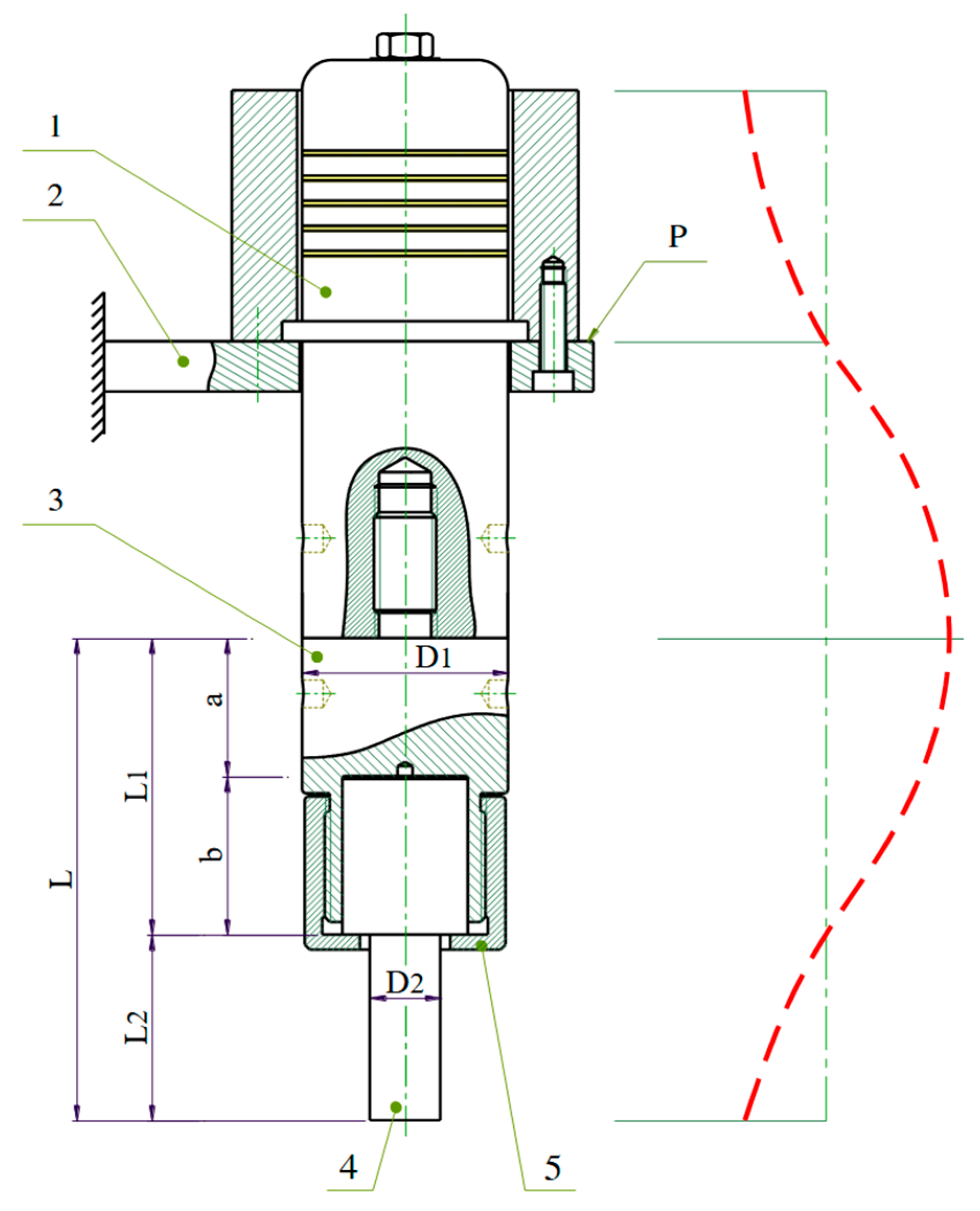
Figure 2 illustrates the structure of the ultrasonic horn assembly used in this study. The transducer (1) is mounted on the EDM machine head (2), and the horn (3) is connected to the transducer via a threaded joint at location P—corresponding to a displacement node (zero-amplitude point) during longitudinal vibration. The lower end of the horn includes a through-hole (4) for mounting the workpiece, which is secured in place using a clamping nut (5).
To simplify modeling and fabrication, the horn in this research is idealized as consisting of two coaxially connected cylindrical segments of different diameters, both made from the same material (90CrSi). The first (upper) segment has a diameter of D
1 = 41 mm, equal to the outer diameter of the transducer at the mounting location. The second (lower) segment has a diameter of D
2 = 14 mm and a length of L
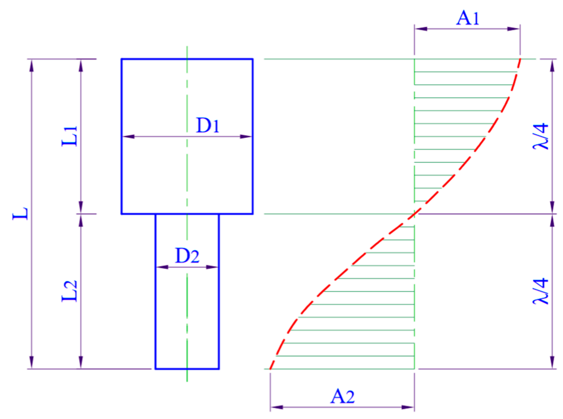
2 = 27 mm, which is based on the geometric dimensions of the actual punch used for forming pharmaceutical tablets. The horn’s vibration distribution can be illustrated in
Figure 3.
The objective is to determine the optimal length of the upper segment L
1, which ensures that the horn operates in resonance and effectively transmits ultrasonic energy to the workpiece during EDM. However, to reduce the time and cost associated with full horn optimization, the length L
1 is redefined as the sum of two components, L
1 = a + b, where a = 37 mm is a fixed value determined by the mechanical space required for mounting the horn to the transducer; b is the only unknown to be optimized in this study.
where f = 20,000 Hz is the frequency of ultrasonic vibration;
c is the wave speed in the horn material. As the horn material is 90CrSi tool steel,
c is calculated by
where
E is the Young’s modulus (Pa);
E = 205 × 10
9 Pa;
is the density (kg/m
3) of the material:
= 7850 kg/m
3; yielding a wave speed of
The wavelength of longitudinal wave at the excitation frequency f = 20,000 Hz is
Substitute (4) into (1) to get
2.3. Experimental Validation of Horn Length
To determine the optimal length L for the ultrasonic horn, an experimental validation process was carried out in two stages.
The objective of this step was to determine the horn length that produces the maximum vibration amplitude at a fixed frequency of 20 kHz. Based on the theoretical resonance condition described in Equation (5), the target horn length was calculated as L = 127.75 mm. To experimentally verify this and identify the length corresponding to peak amplitude, four horn prototypes were fabricated with total lengths of 125, 126, 127, and 128 mm. These lengths were realized by varying the design parameter bb from 61 to 64 mm in 1 mm increments, while keeping a = 64 mm fixed in the overall length expression L = a + b.
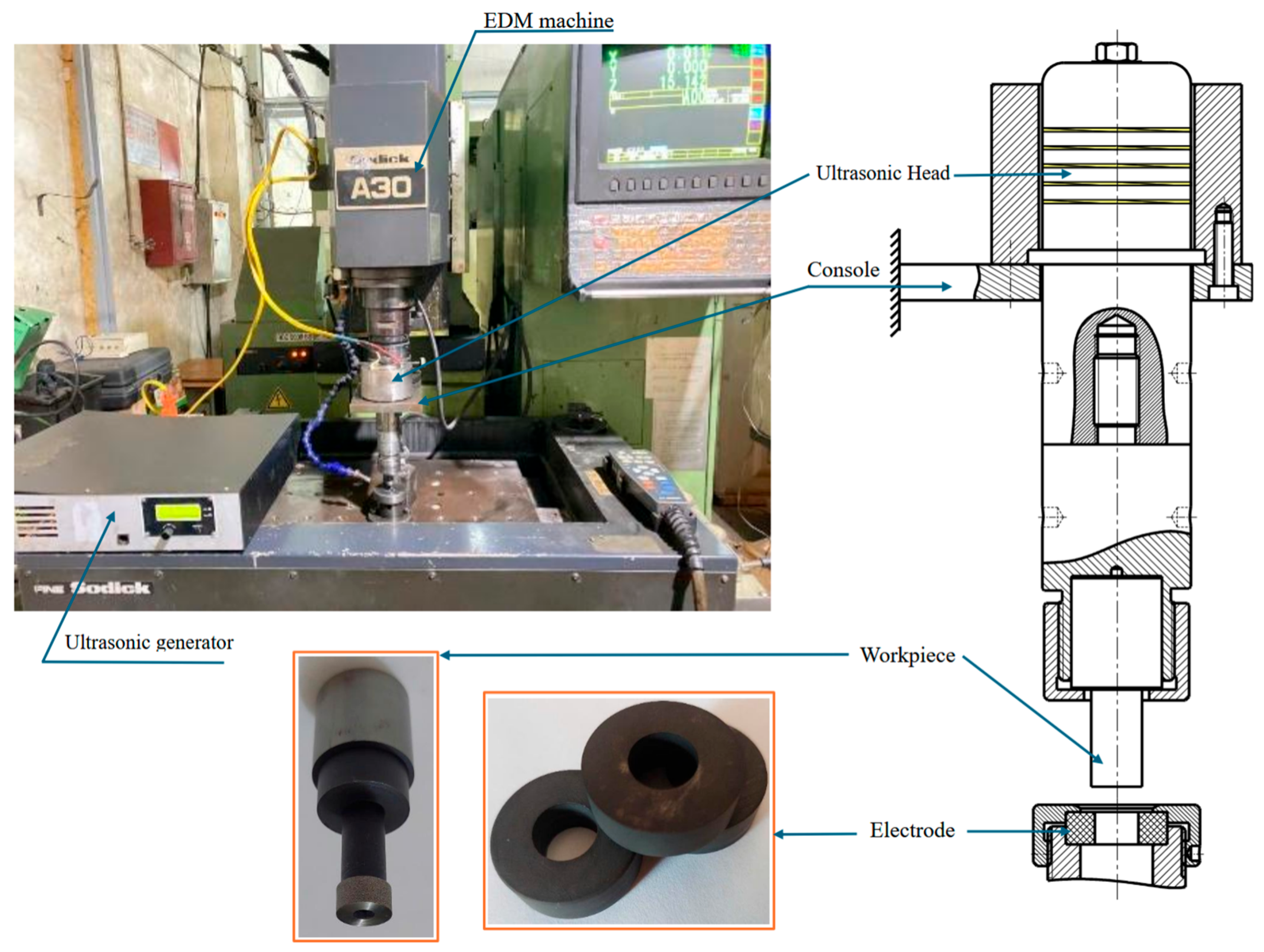
The axial vibration amplitude of each horn was measured using a commercial laser displacement sensor (Keyence LK-H055, Keyence Corporation, Japan). The experimental setup is illustrated in
Figure 4. Each horn was mounted on the ultrasonic system, excited at a constant frequency of 20 kHz, and the vibration amplitude at the free end was recorded.
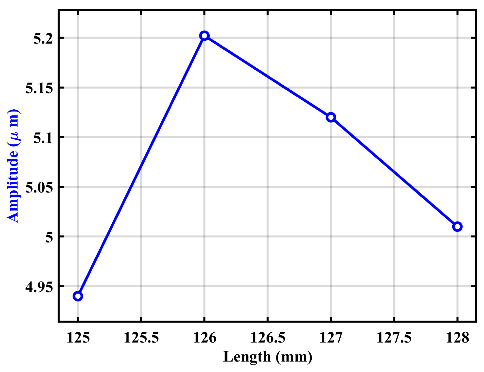
The measured amplitudes corresponding to different horn lengths are summarized in
Table 1. Additionally, the relationship between total horn length and vibration amplitude is presented in
Figure 5. These results were used to identify the optimal horn length that maximizes vibration amplitude and ensures resonance at the intended frequency.
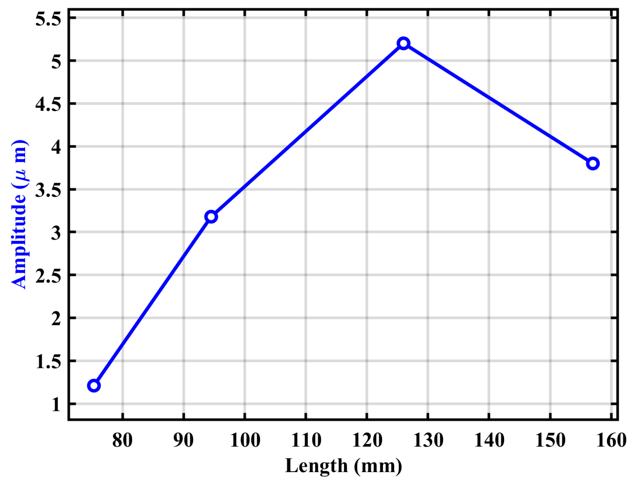
Following the identification of the horn length that yielded the maximum vibration amplitude (126 mm), this step aimed to establish additional horn configurations to support the Box–Behnken design (BBD) used in the experimental phase of the UV-EDM optimization. In the BBD, the ultrasonic vibration amplitude (A) is treated as one of the five input variables, and it must be defined at three distinct levels to enable the construction of quadratic models and capture potential non-linear effects.
The highest amplitude measured in Step 1 was 5.2 µm at L = 126 mm, which was selected as the high-level value for parameter A. To define the remaining two amplitude levels (1.2 µm and 3.2 µm), additional horn prototypes were fabricated by adjusting the parameter b, thereby modifying the total horn length L = a + b.
Through experimental measurements similar to Step 1, the corresponding horn lengths that yielded the target amplitudes were determined. The results are summarized in
Table 2, which presents the values of bb, the resulting horn lengths L, and the associated amplitudes A. The relationship between horn length and vibration amplitude is visualized in
Figure 6, confirming a resonance-sensitive, non-linear trend. This information provided a practical basis for selecting appropriate horn lengths corresponding to low, medium, and high levels of ultrasonic amplitude for use in the BBD matrix.
2.4. Modal Simulation of the Horn
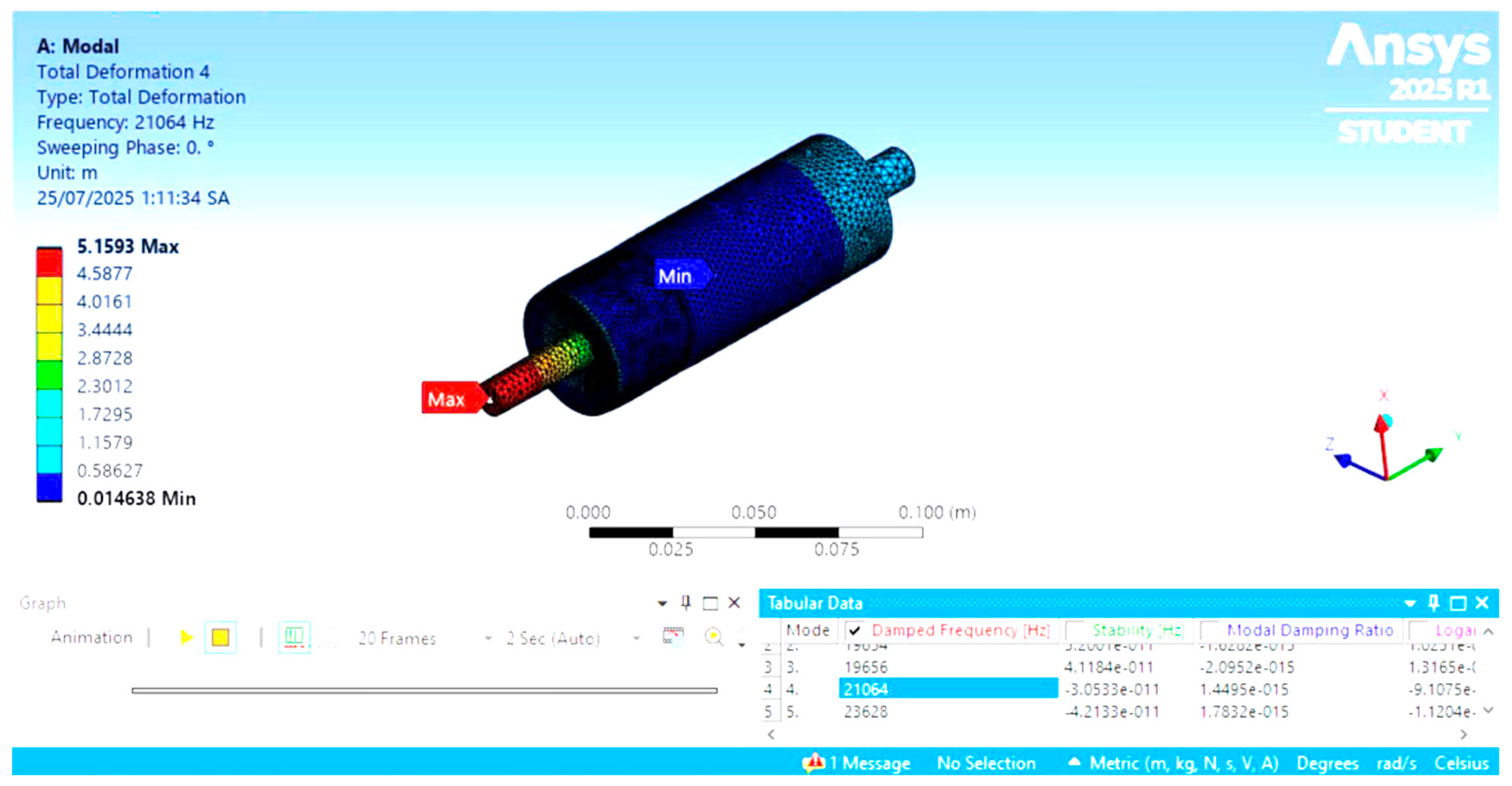
To further verify the resonant behavior of the ultrasonic horn, a modal analysis was performed using ANSYS 2025 R1. The simulation aimed to identify the natural frequencies and corresponding mode shapes of the horn to ensure that its longitudinal vibration mode matches the target resonant frequency of 20 kHz.
The model geometry corresponded to the actual horn configuration described in
Section 2.2, with clamped boundary conditions at the horn–transducer interface and a free end at the workpiece side. The horn material was 90CrSi tool steel, with the following material properties: Young’s modulus
E = 205 GPa, density
= 7850 kg/m
3, and Poisson’s ratio ν = 0.3.
Figure 7 shows the simulation result for the fourth mode shape. The modal analysis identified a longitudinal vibration mode at a frequency of 20,413 Hz, which is very close to the target operating frequency of 20 kHz. The total deformation plot indicates a clear anti-node at the free end of the horn, where the workpiece is mounted, confirming that the maximum vibration amplitude occurs at the machining interface.
Table 3 summarizes the first five natural frequencies obtained from the simulation. Among them, mode 4 corresponds to the desired longitudinal vibration, while other modes are transverse or torsional and lie outside the frequency range of interest.
The frequency and mode order from the simulation are summarized in
Table 3. The fourth mode corresponds to the axial vibration, while other modes are transverse or torsional and outside the frequency range of interest.
It is important to note that the modal simulation was conducted after the experimental optimization presented in
Section 2.3. Its purpose is not to determine the horn geometry but to validate that the optimized horn structure resonates near the desired frequency. This sequencing reflects the actual research process, where theoretical design and physical tuning were followed by numerical verification to ensure consistency and support the final design decision.
The simulation results thus confirm that the horn is properly dimensioned for stable and efficient ultrasonic resonance near 20 kHz, suitable for UV-EDM applications.
4. Results and Discussion
4.1. Pareto Optimization Using NSGA-II and GPR Surrogates
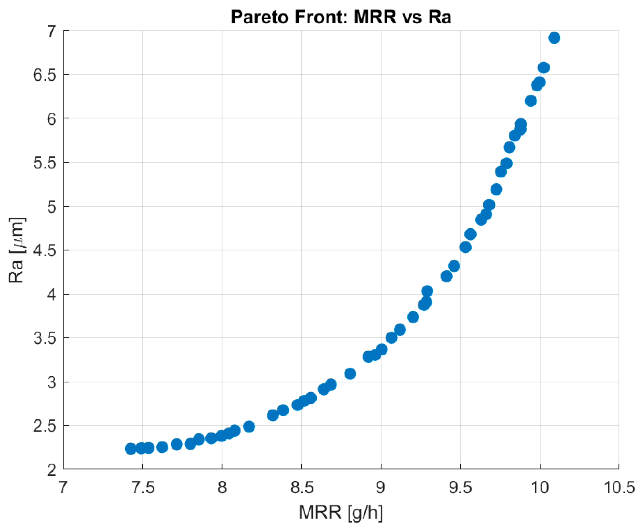
A customized MATLAB-based NSGA-II algorithm was used to optimize two conflicting objectives—maximizing MRR and minimizing Ra—in ultrasonic EDM. Surrogate models for both responses were trained using Gaussian Process Regression (GPR) after applying Box–Cox transformations to reduce skewness and stabilize the variance of the experimental data. The squared exponential kernel was chosen for its smoothness and good performance in small datasets. The algorithm was configured with 50 individuals and 100 generations.
Figure 9 illustrates the resulting Pareto front. It captures a smooth distribution of non-dominated solutions that clearly reflects the trade-off between MRR and Ra: as MRR increases, Ra also tends to increase.
4.2. Analysis of Parameter Effects and Trade-Off Behavior
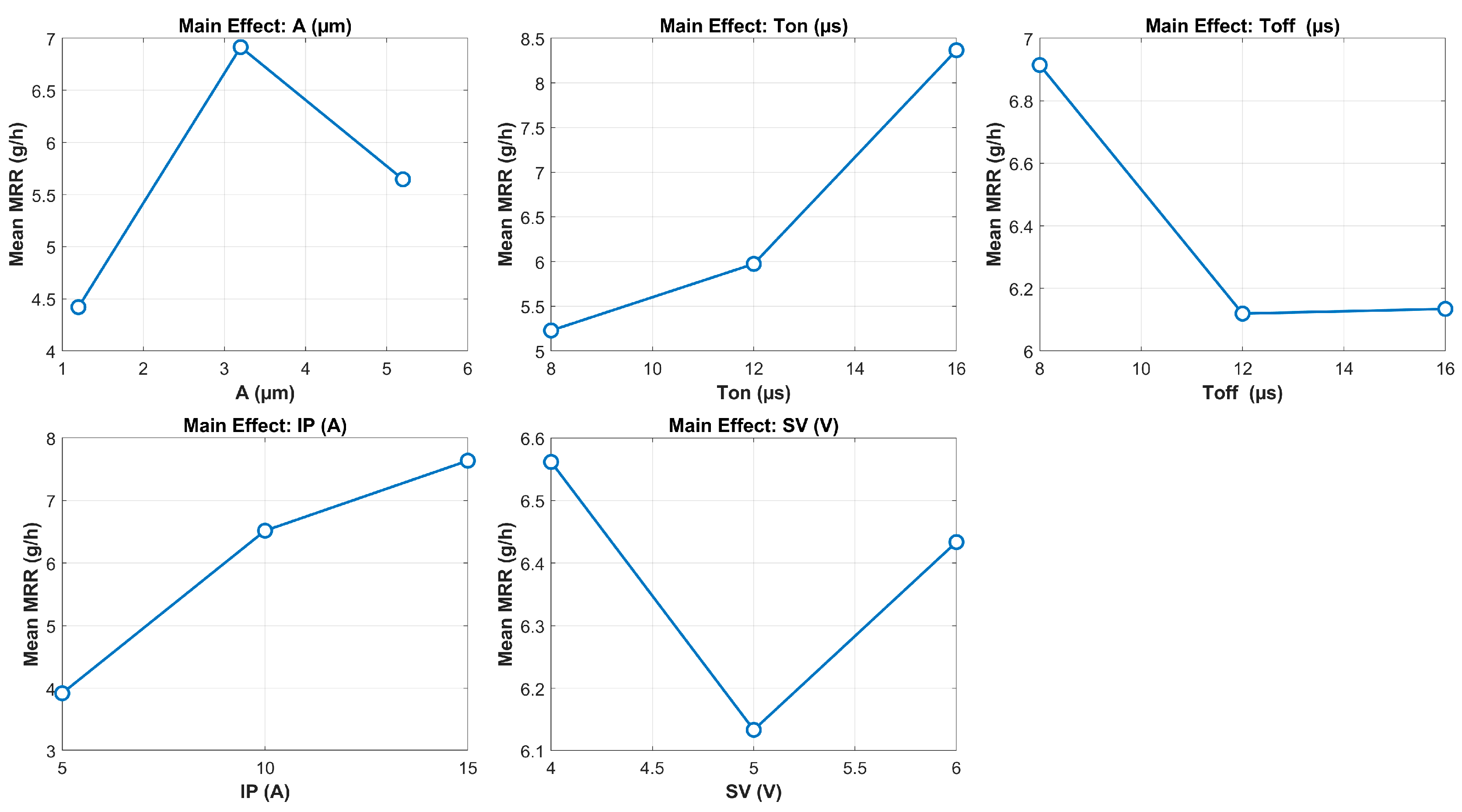
To further understand how the process parameters affect the responses, main effect plots for MRR and Ra were generated based on the experimental data.
Figure 10 shows that material removal rate (MRR) is significantly influenced by all five input parameters. MRR increases with rising values of ultrasonic amplitude (A), pulse-on time (Ton), and peak current (IP), which is consistent with the known behavior of EDM where higher discharge energy promotes faster material removal. Among these, IP exhibits the strongest positive effect on MRR. Interestingly, MRR does not increase monotonically with amplitude. Instead, a distinct peak is observed at a moderate amplitude value (approximately 3.2 µm), after which further increases in amplitude lead to a reduction in MRR. This indicates the existence of an optimal vibration amplitude for maximizing material removal. Beyond this point, excessive vibration may lead to unstable discharge conditions or ineffective energy transfer due to poor spark localization. This observation is also consistent with the findings reported in [
30], where both MRR and tool wear rate were shown to increase with ultrasonic amplitude up to a certain threshold, beyond which a decline was observed due to the increased frequency of short-circuiting events. Additionally, a longer pulse-on time (T
on) favors material removal by extending discharge duration, whereas a shorter pulse-off time (T
off) helps increase spark frequency, with both contributing positively to MRR. The influence of servo voltage (SV) is relatively minor in comparison to the other parameters.
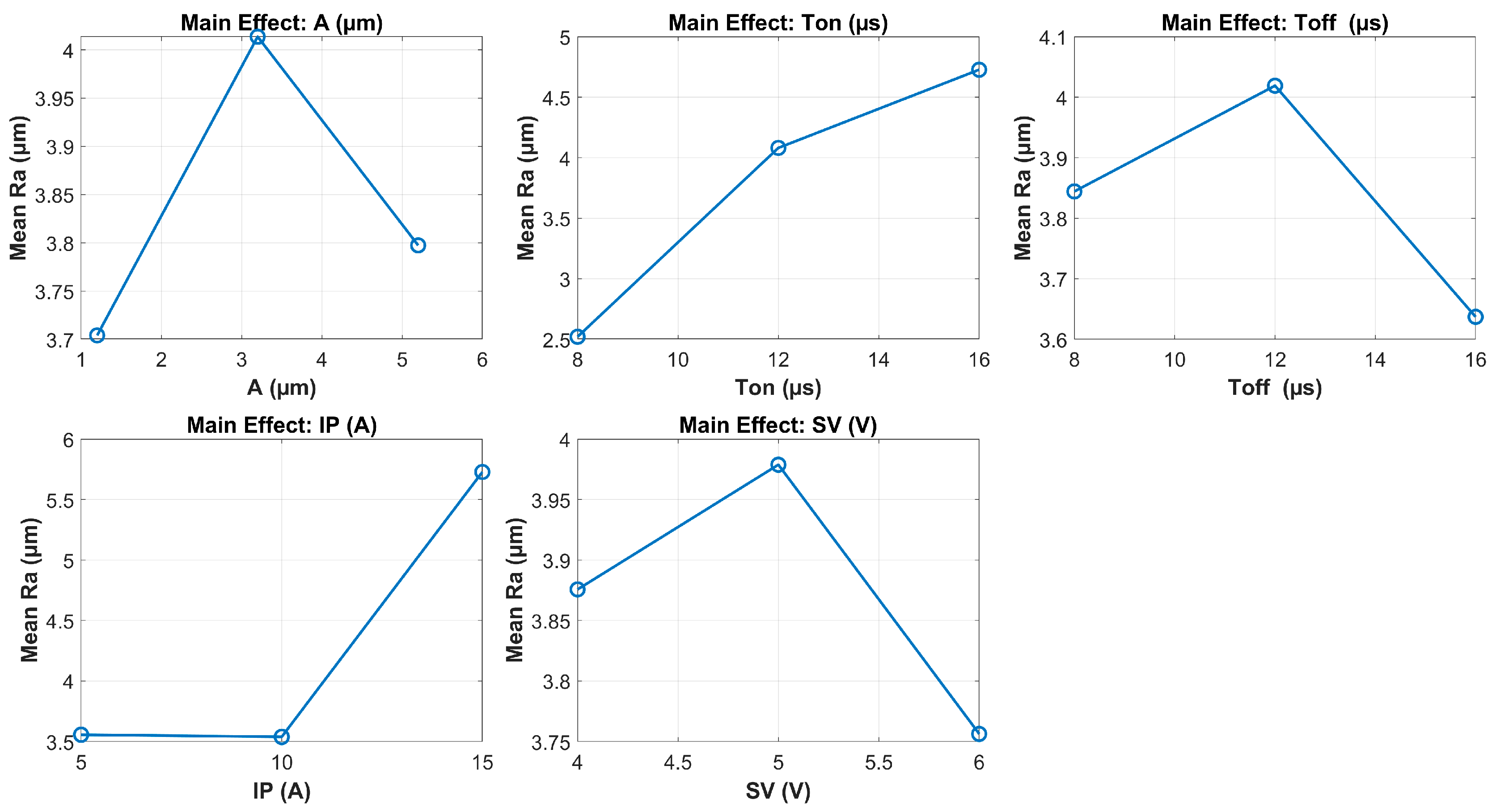
In contrast, the main effect plots for surface roughness (Ra) shown in
Figure 11 highlight distinct trends for each input parameter. Among the five factors, peak current (IP) and pulse-on time (Ton) exhibit the strongest influence on Ra. As IP increases, Ra rises significantly, particularly from 10 A to 15 A. This trend is consistent with the expected thermal effects of a higher discharge energy, which causes deeper and wider craters on the machined surface. Ton also has a pronounced effect: increasing T
on leads to a steady rise in Ra. Longer pulse durations allow more energy to be delivered per spark, which intensifies material melting and deteriorates surface finish.
The influence of pulse-off time (Toff) is more nuanced. Ra initially increases with Toff up to 12 µs, then decreases beyond this point. This suggests that at moderate Toff values, insufficient time for debris evacuation may lead to unstable discharges, whereas at longer Toff, spark frequency decreases and thermal accumulation is reduced, improving surface quality. Regarding ultrasonic amplitude (A), a non-monotonic relationship is observed. Ra increases from 1 to 3.2 µm, then decreases as amplitude continues to 5.2 µm. This pattern indicates that while moderate UV may introduce instability, a higher amplitude improves debris flushing and stabilizes discharge conditions, leading to smoother surfaces. Lastly, servo voltage (SV) shows a slight non-linear influence: Ra peaks at 5 V and decreases at both lower and higher values. However, its overall effect remains relatively minor compared with the other parameters.
It is worth noting that the highest surface roughness observed in the experimental matrix was 10.627 µm (Group 40), which is significantly higher than the rest of the data points. This occurred at the combination of Ton = 16 µs and Ip = 15 A—the highest pulse duration and peak current values in the design space. Such high-energy settings lead to excessive material melting and unstable discharge conditions, resulting in larger and deeper craters on the machined surface.
This phenomenon is not unique to the present study. Similar trends have been reported in prior research. For example, in [
31], an Ra value of 8.4 µm was observed at Ton = 150 µs and Ip = 5 A, whereas most other values remained below 3 µm. Likewise, in [
26], an Ra of 7.031 µm was recorded at Ton = 16 µs and Ip = 7 A. These results collectively confirm that high surface roughness outliers in EDM are consistently associated with extreme discharge energy conditions.
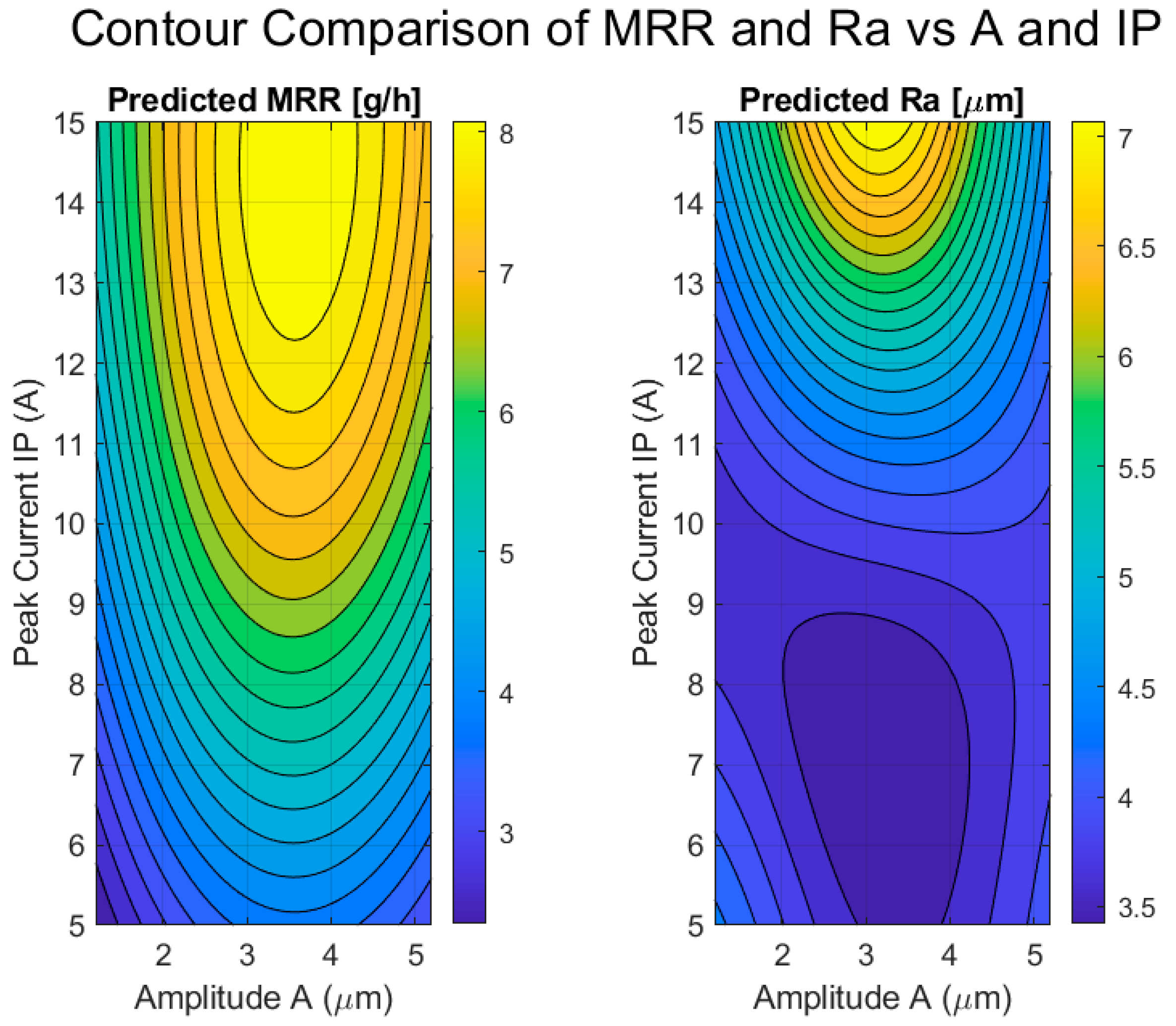
Figure 12 illustrates the predicted effects of ultrasonic vibration amplitude (A) and peak current (IP) on both material removal rate (MRR) and surface roughness (Ra), as obtained from the trained GPR models. These two input variables were selected for contour analysis due to their dominant influence on both objectives, as confirmed by the main effect plots.
In the left subplot, MRR is shown to increase significantly with both amplitude and peak current. The highest MRR values (above 8 g/h) are achieved when A ≈ 3.0–4.0 μm and IP ≈ 13–15 A. This synergistic effect is expected, since a higher ultrasonic amplitude enhances debris removal through cavitation and micro-agitation, while an increased current delivers more discharge energy per pulse, accelerating material removal.
Notably, the MRR surface shows a wide, flat peak region, suggesting process robustness across a range of high-energy input conditions.
The right subplot presents the predicted Ra contours over the same parameter space. As expected, Ra increases with IP due to stronger thermal effects and deeper crater formation. However, Ra exhibits a non-linear relationship with amplitude. Ra reaches a maximum at around A ≈ 2.5–3.0 μm, but decreases notably as A increases toward 5 µm. This behavior may be attributed to unstable spark initiation at moderate amplitudes, while higher amplitudes improve discharge consistency and debris ejection, leading to smoother surfaces.
Together, these plots reveal a favorable operating window in the region of A = 3.5–4.5 μm and IP = 11–13 A, where a high MRR can be achieved while keeping Ra below the acceptable threshold of 4 µm. This insight is particularly valuable for selecting robust and efficient process settings in ultrasonic EDM applications.
4.3. AHP-Based Selection with Surface Roughness Constraint
The Analytic Hierarchy Process (AHP) was applied to rank these solutions based on prioritized objectives. In the pairwise comparison matrix, MRR was considered three times more important than Ra, reflecting the emphasis on maximizing productivity while still maintaining acceptable surface quality. From this matrix, relative weights were computed as w
MRR = 0.75 and w
Ra = 0.25. Importantly, only Pareto solutions satisfying Ra ≤ 4 μm were retained for evaluation. This constraint was imposed based on practical requirements for the EDM of external cylindrical surfaces of punch tools, where surface roughness above this threshold typically leads to excessive wear, compromised dimensional precision, and poor contact performance. Each filtered solution was then scored using a weighted normalization of the two objectives. The solution with the highest AHP score was selected as the optimal configuration. The final result, summarized in
Table 5, represents a well-balanced solution achieving both a high machining efficiency and acceptable surface integrity.
4.4. Comparative Evaluation with Conventional EDM
To assess the effectiveness of ultrasonic vibration in enhancing EDM performance, a comparison was conducted between the optimal results obtained in this study (with ultrasonic vibration) and those reported in [
28], which applied the same multi-objective optimization framework (NSGA-II combined with AHP) to the EDM process using graphite electrodes—but without ultrasonic assistance.
Table 6 summarizes the optimal machining parameters and outcomes from both studies. In the present work, ultrasonic vibration significantly increased the material removal rate (MRR) from 5.91 g/h (conventional EDM) to 9.28 g/h—representing a 36.31% improvement. This enhancement is attributed to improved flushing, spark stability, and energy efficiency due to ultrasonic vibration at an amplitude of 3.29 µm.
However, a slight trade-off in surface finish was observed. The optimal surface roughness (Ra) increased from 3.15 µm (no UV) to 3.91 µm (with UV), though still within the acceptable threshold of 4 µm for punch tool applications. This confirms that while UV enables more aggressive machining conditions, surface integrity can still be preserved within practical limits.
This comparison highlights two key advantages of UV-EDM: Firstly, the process supports higher energy levels (greater Ton and IP) while maintaining process stability, leading to significantly improved material removal rates. Secondly, despite a modest increase in Ra, the surface quality remains within functional limits, suggesting that UV enables more efficient yet controlled machining.
In conclusion, the addition of ultrasonic vibration not only enhances EDM efficiency but also enables the use of higher energy input parameters while maintaining acceptable surface quality. This makes the UV-EDM process particularly suitable for applications that demand both high productivity and reliable surface integrity, such as the fabrication of precision punch tools. This aligns with broader trends in advanced manufacturing, where engineered surfaces are increasingly designed not only for dimensional accuracy or roughness targets, but also to impart specific functional enhancements—such as wear resistance, corrosion protection, or biocompatibility. Bui V.D. [
33] noted that nano-structured antibacterial coatings produced by powder-mixed EDM with silver nanoparticles can improve coating durability through deeper and more uniform silver incorporation. These modified surfaces also demonstrated good biocompatibility, supporting osteoblast attachment and growth, which are essential factors for promoting osseointegration in medical implants.
5. Conclusions
This study presented an integrated framework for optimizing ultrasonic vibration-assisted EDM (UV-EDM) applied to the external cylindrical surface machining of punch tools using graphite electrodes. The research was carried out in three main phases: horn design, experimental evaluation, and multi-objective process optimization using NSGA-II and AHP.
In the first phase, a stepped cylindrical horn was designed to operate in longitudinal resonance at 20 kHz. The theoretical length of the horn was calculated based on the half-wavelength condition, considering the material properties of 90CrSi steel and actual constraints related to punch geometry and machine configuration. Experimental validation confirmed that the horn achieved the required resonance condition with maximal vibration amplitude when the total length was tuned to 126 mm.
In the second phase, a Box–Behnken design of experiments was conducted with five process variables: ultrasonic amplitude, pulse-on time, pulse-off time, peak current, and servo voltage. Surface roughness (Ra) and material removal rate (MRR) were selected as performance indicators. The results demonstrated that both Ra and MRR are strongly affected by amplitude and peak current, while the effects of Ton and Toff vary non-linearly. Ultrasonic vibration showed a clear benefit in enhancing MRR without significantly degrading surface quality.
In the final phase, surrogate models were constructed using GPR and used in a custom MATLAB-based NSGA-II algorithm to generate the Pareto front. The optimal solution was selected from the non-dominated set using the AHP, under the constraint Ra ≤ 4 μm, which was derived from practical punch manufacturing requirements. The selected configuration achieved a high MRR of 9.28 g/h while maintaining the Ra at 3.91 µm, confirming the practical value of the hybrid optimization approach.
Furthermore, a comparative analysis with previous studies revealed that the use of ultrasonic vibration in EDM significantly enhances machining efficiency. In particular, the optimized MRR achieved in this study (9.28 g/h) was 36.31% higher than that obtained in a comparable EDM process using a graphite electrode but without ultrasonic assistance (5.91 g/h). This highlights the effectiveness of ultrasonic vibration in accelerating material removal while preserving surface integrity.


