Abstract
The ongoing rise in global electricity demand highlights the need for advanced, efficient, and environmentally responsible energy conversion technologies. This research presents a comprehensive design, modeling, and experimental validation of a tubular permanent magnet linear alternator (PMLA) integrated with a free piston engine system. Linear alternators offer a direct conversion of linear motion to electricity, eliminating the complexity and losses associated with rotary generators and enabling higher efficiency and simplified system architecture. The study combines analytical modeling, finite element simulations, and a sensitivity-based design optimization to guide alternator and engine integration. Two prototype systems, designated as alpha and beta, were developed, modeled, and tested. The beta prototype achieved a maximum electrical output of 550 W at 57% efficiency using natural gas fuel, demonstrating reliable performance at elevated reciprocating frequencies. The design and optimization of specialized flexure springs were essential in achieving stable, high-frequency operation and improved power density. These results validate the effectiveness of the proposed design approach and highlight the scalability and adaptability of PMLA technology for sustainable power generation. Ultimately, this study demonstrates the potential of free piston linear generator systems as efficient, robust, and environmentally friendly alternatives to traditional rotary generators, with applications spanning hybrid electric vehicles, distributed energy systems, and combined heat and power.
1. Introduction
Global electricity consumption is steadily increasing, reaching nearly 30,966 TWh with an average annual growth of around 1.3% over the past decade [1]. The electric power sector continues to rely heavily on fossil fuels for power generation, making electricity generation a major source of global CO2 emissions. This sector is responsible for roughly one-third of all annual greenhouse gas (GHG) emissions [2]. The resulting climate impact has created an urgent need to develop new technologies to reduce CO2/NOx emissions, increase energy production, and increase the efficiency of power generation systems. Improving efficiency is one of the most effective ways to achieve these goals, as greater efficiency means less fuel is needed for the same output, which directly reduces GHG emissions. Consequently, many countries are therefore prioritizing the development of higher-efficiency engines and generators as part of their sustainable energy and climate policies [3]. In this context, innovations that increase conversion efficiency, such as minimizing waste heat or friction losses, are in high demand to meet growing energy needs while reducing environmental costs.
Conventional rotary electric generators, along with the systems that drive them, have inherent limitations when interfacing with reciprocating or linear energy sources. These systems typically require a crankshaft, gearbox, or similar mechanism to convert linear motion into rotational motion, resulting in numerous moving parts and complex mechanical assemblies [4]. Such additional components increase the system’s overall volume and introduce friction and wear. As the number of moving parts increases, so do the maintenance requirements. For example, in a traditional piston engine, the slider-crank linkage creates lateral forces on the piston, which leads to significant frictional and subsequent thermal losses during operation [5]. In some cases, the hardware used to transfer linear to rotational motion can also introduce reliability issues or even environmental hazards, such as hydraulic oil leakage from gearboxes. By eliminating or reducing frictional and associated thermal losses through direct conversion of the linear motion to electricity, it becomes possible to achieve higher conversion efficiency.
To address the need for higher-efficiency power generation, this study experimentally demonstrates a free piston linear generator (FPLG). A computationally guided approach is used to select key two-stroke engine design parameters, which are then coupled with a permanent magnet linear generator. The study concludes with the demonstration of power generation from two prototype systems. One of the primary hypotheses tested is that planar flexure springs can serve as an energy storage device, improving system stability and enabling high-frequency operation.
1.1. Background on Linear Generators
A linear generator, also known as a linear alternator (LA), is a type of electrical generator that converts linear motion directly into electrical energy without requiring rotary motion or complex mechanical linkages. Unlike traditional rotary generators, linear generators provide a more efficient and compact solution for harnessing energy from sources that naturally produce linear movement. This type of motion is found in a variety of generator systems (GENSETs), including but not limited to (1) free piston engines [6,7,8,9], (2) wave energy converters [10], (3) hybrid vehicles [11,12], (4) micro-energy harvesters [13], and (5) supercritical CO2 expanders [14].
The key difference between rotary generators and linear generators is that rotary generators require a crankshaft to convert linear motion into rotary motion. Figure 1 presents a flow chart comparing the energy pathways of rotary generators (top of Figure 1) and linear generators (bottom of Figure 1). Efficiency improvements can be achieved by eliminating the crankshaft, as evidenced by the absence of a crankshaft loss term for the linear generator in Figure 1. Using a linear generator eliminates the frictional losses associated with the crankshaft mechanism, thereby increasing the overall efficiency of electrical power delivery. Additionally, in rotary engines, the crankshaft prescribes the motion of the piston, whereas in free piston systems, this constraint is absent.
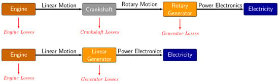
Figure 1.
Flowchart comparing rotary and linear electric generators used in engine generator systems. The top flowchart for rotary generators illustrates losses associated with the engine, crankshaft, and generator. The bottom flowchart, representing linear generators, eliminates losses related to the crankshaft.
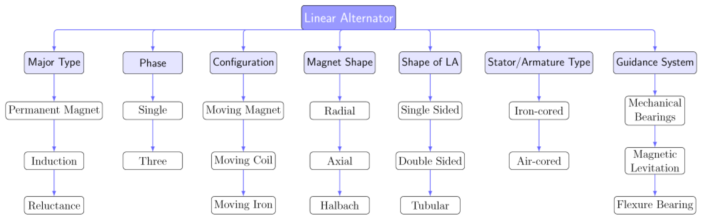
While the components of a linear generator are similar to those of a rotary generator, their arrangement differs. Figure 2 summarizes the critical components of a linear generator. Linear generators are generally classified as permanent magnet, induction, or reluctance types, with electrical phases typically configured as either single-phase or three-phase, depending on pole placement. The movement of components further distinguishes generator types, resulting in moving magnet, moving coil, or moving iron configurations. The magnetic flux arrangement, which determines flux direction, may be radial, axial, or Halbach. Magnet placement defines the geometry of the generator, producing single-sided, double-sided, or tubular designs. The stator or armature can be either iron-cored or air-cored. Additionally, the mechanism supporting the translator typically uses linear mechanical bearings, magnetic levitation, or flexure bearings. For this study, we specifically examine a permanent magnet design configured as a single-phase, moving magnet system with axial flux, a tubular geometry, an iron-cored stator, and flexure bearings to guide the translator relative to the stator.
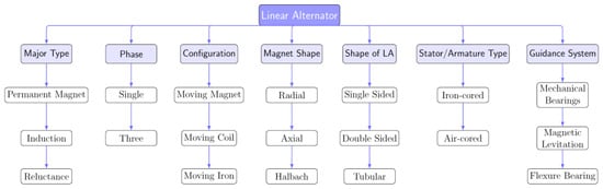
Figure 2.
Classification of linear alternator components. This study focuses on a permanent magnet, single-phase, moving magnet design with axial magnetic flux, tubular geometry, iron-cored stator, and flexure bearing guidance.
1.2. Free-Piston Integration with Linear Generator
Integrating a free piston engine with a linear generator creates a free piston linear generator (FPLG). In this configuration, the engine’s pistons do not connect to a crankshaft; instead, they drive a linear alternator to produce electrical power directly. Free-piston engine concepts have been studied for decades. For example, Wang et al. [4] provide a comprehensive review of their historical development and application. As noted above, FPLG designs achieve superior thermal efficiency due to the absence of a crank mechanism. More importantly, these designs benefit from advanced combustion dynamics, such as variable compression ratios and multi-fuel capability, which can further enhance the efficiency of the power conversion process [4].
More recently, research has focused on achieving low-temperature auto-ignition using stratified-charge compression ignition (SCCI) and controlled auto-ignition (CAI), the latter being a type of homogeneous charge compression-ignition (HCCI) strategy [15]. These approaches use techniques such as recirculating exhaust gases, heating the intake charge, and varying compression ratios. HCCI, in particular, offers the advantage of highly efficient and clean combustion. By thoroughly mixing fuel and air before compression, HCCI enables ignition at lower temperatures, which helps to substantially reduce nitrogen oxide (NOx) emissions and particulate formation, while maintaining high thermal efficiency. The variable stroke length and compression ratio available in FPLG architectures are particularly well suited to advanced combustion strategies, such as HCCI, offering unique opportunities to tailor engine operation for optimal performance and reduced emissions. The result is a highly efficient, compact generator that converts fuel to electricity in fewer stages than a conventional engine generator set. The primary advantage of these advanced combustion schemes is that the stroke length and resulting compression ratios are not fixed and can be adjusted during startup or dynamically from cycle to cycle.
A notable application of free piston engine generators (FPEGs) technology that has garnered attention is its use as a range extender in hybrid electric vehicles, largely due to its ability to support advanced combustion strategies, such as HCCI. In this role, a free piston engine coupled with a linear alternator functions as an onboard power generator to recharge the battery or supply driving power as needed. The main appeal of FPLGs in hybrid vehicles lies in their potential to achieve higher efficiency and lower emissions through advanced combustion schemes, such as HCCI, compared to conventional rotary generators. This leads to improved fuel economy and reduced environmental impact. Additionally, the inherent flexibility of FPLGs allows for the use of various fuels, further enhancing their suitability for automotive applications. Recent reviews have reported the successful use of free piston linear engines for generating electric power in hybrid vehicles, validating their feasibility as range extender technology. Prototype dual-piston FPLG systems have been built and tested for automotive use, demonstrating promising results in power output, fuel flexibility, and responsiveness, which make them strong candidates for next-generation hybrid drivetrains [5].
1.3. Challenges in Designing and Operating FPEGs
Various configurations of free piston engine generators exist, including single-cylinder, dual-cylinder, and opposed-piston designs. The German Aerospace Center (DLR) has worked extensively on FPEG technology, developing experimental test rigs to assess system performance and potential [11]. The use of a permanent magnet linear alternator as a motor for engine startup, transitioning to generator mode once stable operation is achieved, has also been demonstrated in the literature [12]. General Motors [16] implemented control schemes that use bounce chambers and electrical braking and introduced an electrical flywheel system to compensate for variable compression ratios in FPEG systems. Similarly, Toyota [17] employed a bounce chamber with pressure regulation to adjust the stiffness of the gas spring system and collaborated with DLR to refine this configuration.
In this study, West Virginia University (WVU) has demonstrated the use of helical and flexure springs as alternatives to bounce chambers, achieving comparable power generation results. In previous studies, WVU demonstrated two back-to-back pistons coupled with a linear generator, producing 316 W of electric power at a reciprocating frequency of 23.1 Hz and a stroke length of 42 mm [18]. WVU continues to advance this technology by increasing stability and power density through the use of flexure bearings instead of bounce chambers. More recently, WVU has applied the FPEG to co-power generation in a 1 kW natural gas generator for domestic power and heat production.
Among the FPEG systems reported in the literature, the following groups have provided experimental demonstrations of free piston linear alternator systems: DLR [11], Toyota [17], Sandia National Laboratories [19], and West Virginia University [18].
For FPEG technology to be commercially viable and competitive with rotary generators, the operating frequency must be increased. Higher frequencies lead to greater power density, allowing the system to reach performance thresholds that make it competitive with other power systems, including batteries. The primary challenge, however, lies in increasing the operating frequency while minimizing losses associated with the energy storage device, whether it is a bounce chamber or an alternative mechanism. Among the most promising approaches is the use of flexure bearings, as employed in this work, though their application is ultimately limited by the fatigue properties of modern metallic alloys. Compounding the losses is the fact that as we strive to achieve higher energy density (power per stroke), the restoring force (stress or pressure) required of these storage devices also increases, which is proportional to the losses. Therefore, the design of the FPEG, like most power systems, becomes a system optimization problem that is ultimately limited by current material properties.
2. Analytical Modeling of Tubular Linear Alternators
Often, the most challenging aspect of a FPEG system is the linear alternator design. Research focused on the design of linear alternators has been discussed extensively over the years [20,21,22], which provides basic design guidelines for alternator designs. Further optimization for the magnet position and type of magnet orientation is discussed in [23,24], where different orientations, such as radial, axial, and Halbach orientation of magnets, provide different performance. Losses in linear alternators have been discussed in [25], where the different losses in linear alternators, such as core loss, copper losses, are discussed and calculated experimentally.
A basic design guideline for a three-phase PMLA system was provided in [20,21] by Boldea and Nassar. These papers mainly focus on a three-phase linear alternator design for Stirling engines and high-power applications (greater than 10 kW). As highlighted in Figure 2, the LA can be either a permanent magnet or an induction, or a reluctance type. The moving part of the PMLA can be either windings (coil), magnets, or iron. A moving coil linear generator will have a higher moving mass compared to a moving magnet linear generator because the weight of copper windings would usually be higher than the weight of the magnets for the design of a linear alternator, and therefore, a lower oscillating frequency of the overall system. A moving coil also makes the connection difficult because of the need for some sort of slip strip (similar to a slip ring in rotary electric machines). Moving magnets have issues because of thermal demagnetization and vibrations. Depending on the application, a suitable design has to be decided. In this study, design guidelines are developed for a tubular permanent magnet linear alternator with moving magnets.
Important considerations for single-phase PMLA chosen for this design are: (1) the translator of the PMLA consists of permanent magnets (in this study, axial flux NdFeB magnets), (2) the iron core stator consists of copper windings, and (3) steel laminations. Axial flux magnets are used for the translator. The pole pitch of the linear generator was set equal to the stroke length. The PMLA was a single-phase machine, where the end effects and fringing effects were negligible.
To aid in the design of the PMLA, we develop a simple computational model informed by a more comprehensive finite element model. The length of the stator () can be calculated using the following equation:
where is the engine equilibrium length/stroke length as determined using the two-stroke engine model discussed in the next section. Here, is the number of rotor poles.
The equation to calculate permanent magnet ring thickness MT is
where is to account for any additional air gap between the stator laminations and saturation, the average air gap flux density is , and is the permeability of air.
Using finite element software (FEMM (https://www.femm.info/wiki/HomePage) or Ansys (https://www.ansys.com/products/electronics/ansys-maxwell)), the thickness of the magnets () to achieve a given flux density in the air gap can be calculated.
Here is the energy density, , and .
Energy stored in the airgap between the stator and rotor of the linear alternator is calculated using the rated output power and frequency, and efficiency using the following equation:
where is the energy stored in the air gap, is the rated output power, is the frequency, and is the efficiency.
From the volume of air () required to store the energy, the inner diameter of the stator was calculated using the following equation:
where Ds is the inner diameter of the stator, is the stator length (calculated in Equation (1)), and is the air gap.
The electromagnetic thrust force of the PMLA is given by the equation,
where is the velocity.
The pole pitch and stroke length are equal for a single-phase PMLA. Once the magnet thickness, airgap, and outer diameter of the stator are known, the magnet dimensions are calculated using Equations (12) and (13).
where is the outer diameter of the magnet and is the inner diameter of the magnet.
Next, the number of turns (W1) can be determined using the following equation:
where,
is the open circuit (OC) voltage, and
is the winding factor.
The number of turns per slot () was found using Equation (14) by the following equation,
Here, q is proportional to the number of slots divided by the number of poles and the number of phases.
With the rotor geometry determined, the next step is to determine the stator slot geometry. The rated current is determined based on the power and the rated voltage using the following expression:
The slot geometry was found using the following equation,
where is the fill factor.
The width of the slot () depends on the flux density and saturation of the lamination in the stator. The width of the slot for this system can be chosen between 60 and 75% of the pole pitch.
The slot height () is given by the following equation,
To determine the AWG wire gauge for the PMLA it was necessary to use the peak current in the generator and the number of turns in the system. Once the winding size is known, the resistance of the generator can be found using the following equation,
The inductance of the stator () is calculated using the following,
Using the above equations, the main design parameters both electric and geometric parameters of a linear alternator were determined and used in designing the FPLG. As will be discussed in Section 4, finite element analysis can optimize these parameters and provide the magnetic flux necessary.
3. Analytical Modeling of Two-Stroke Engine
The dynamic behavior of the free piston two-stroke engine, which is coupled to the LA, was simulated using a simple 1D model. The model coupled the in-cylinder thermodynamics with the piston’s equation of motion with a simplified LA waveform. The piston-translator assembly of mass, , moves under the net effect of gas pressure (within the engine cylinder, ), mechanical spring force (), friction force (), and external force from the linear alternator (). Gravity was neglected because the alternator motion was assumed perpendicular to the gravity vector. The instantaneous piston displacement from bottom dead center (BDC) to top dead center (TDC) was denoted by (t) and obeys the following relationship,
Here, is the force due to the in-cylinder pressure P(t), averaged over the piston area (). is the restoring force of the biased springs. is the friction represented by Blair’s two-stroke correlation. is the load from the LA. The alternator load was determined based on the electrical model provided in the previous section. For implementation in this model, we assumed a sinusoidal waveform based on the rated output power of the LA and the frequency of operation.
The gas process combines compression, combustion heat release, and expansion. The instantaneous cylinder volume is determined based on the bore and the instantaneous piston position. Under the ideal gas assumption, the ratio of specific heats () the first law yields
Here the heat release () during combustion is based on a Wibe-type function as a function of the crank angle and determined based on translator position relative to TDC and BDC. The combustion starts once the piston passes TDC and the intake/exhaust ports are closed.
The dynamic compression ratio for each stroke is updated as follows:
where is the exhaust port position to ensure that the trapped volume cannot exceed the exhaust port clearance.
An explicit central finite difference scheme is used with a fixed time step. At each step the sequence is as follows: (1) predict position and velocity, (2) compute pressure and gas forces using Equation (24), (3) evaluate forces (, , ), and (4) update the acceleration () from Equation (23) then correct the velocity and position. The TDC/BDC location is determined when there is a change in the sign of the velocity (). Linear interpolation is used to determine the precise location of TDC and BDC. The output parameters from the model are the positions kinematics (positions, velocity, acceleration), cylinder pressure and temperature, work on the linear alternator and thermal efficiency. Similar to the linear alternator analytics model, this analytical engine model was used in designing the FPLG system. This model was also used in the design space exploration study, which will be discussed in Section 5.
4. Finite Element Simulation of Tubular Linear Alternator
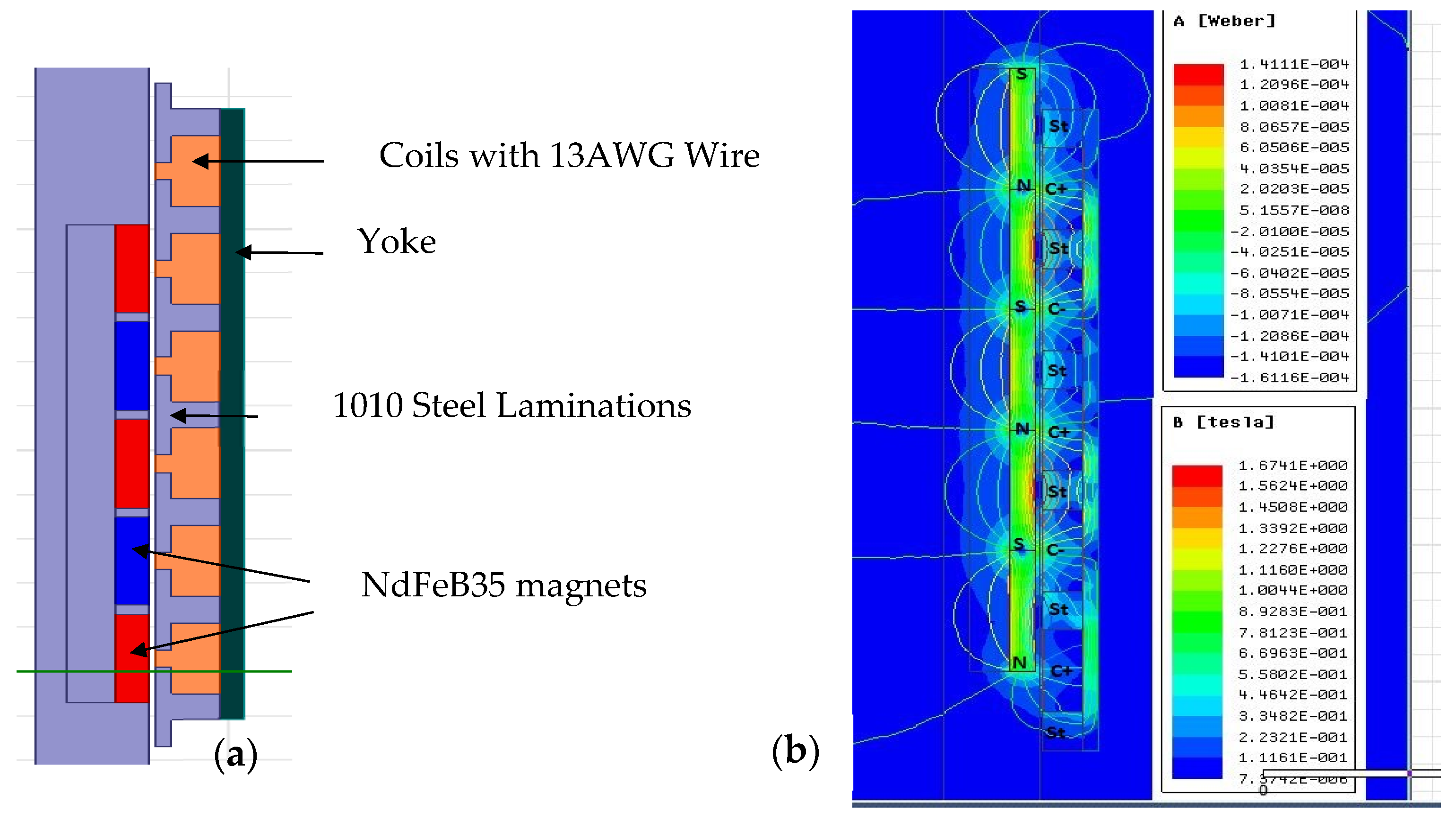
For this study, ANSYS Electronic Desktop software (https://www.randsim.com/software-solutions/electronics/?hsa_acc=5825579003&hsa_cam=9203584742&hsa_grp=149410018543&hsa_ad=664080332609&hsa_src=g&hsa_tgt=kwd-960650391&hsa_kw=ansys%20mechanical&hsa_mt=b&hsa_net=adwords&hsa_ver=3&gad_source=1&gad_campaignid=9203584742, accessed on 10 May 2025) was used to model the linear alternator, utilizing the electromagnetic machine modeling package. Finite element analysis (FEA) was employed for the electromagnetic design of the linear alternators and to inform the analytical model discussed in Section 2. The initial design objective was to build a 1 kW linear alternator. This process involved inputting the complex geometries of the LA, assigning appropriate material properties to each component, and specifying the magnetic properties of the permanent magnetics. The FEA was used to perform electromagnetic parametric analysis to guide the design of the permanent magnet linear alternator and to provide a physical properties for the analytical model discussed in Section 2 and Section 3. The FEA model is shown in Figure 3. This model was also constructed using the FEMM software package [26] and the results between the two different numerical approaches were validated. The axis-symmetric model shown in Figure 3 is a 2D (rz cylindrical) plane model of the linear alternator with axial magnets (NdFeB35) for rotor, and copper windings and 1010 Steel for stator. As shown, the airgap flux density is about 1.1 T.

Figure 3.
(a) FEA schematic model of the PMLA and (b) simulation results of the magnetic flux from the permanent magnets.
The geometric parameters of the chosen configuration are provided in Table 1. The FEA model was analyzed for all the parameters provided in Table 1. A representative power and efficiency plot from the FEA model is shown in Figure 4 and Figure 5. These figures were generated by integrating FEA results into SIMULINK model of FPLG system.

Table 1.
Geometric parameters of the theoretical 1 kW PMLA system.
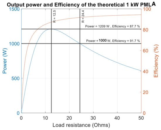
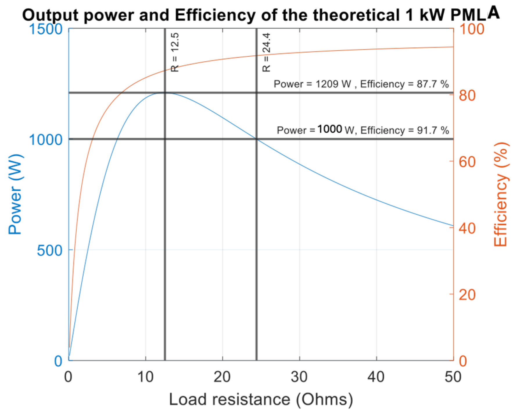
Figure 4.
Power (blue) and efficiency (red) for the theoretical 1 kW PMLA system. The peak of the power curve was optimized based on the LA geometries and machine parameters provided in Table 1.
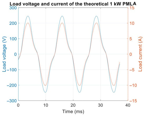
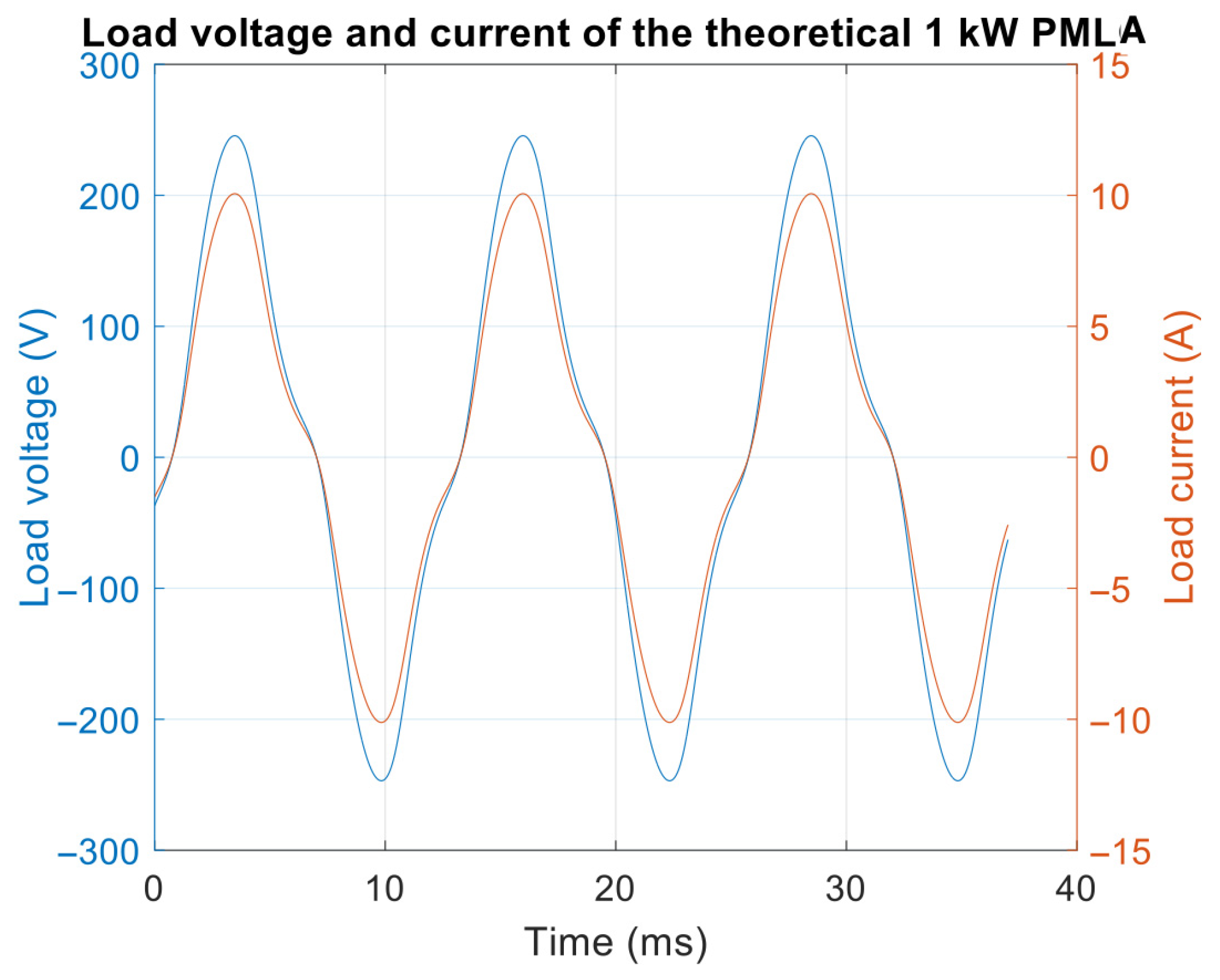
Figure 5.
Load voltage (blue) and load current (red) of the theoretical 1 kW PMLA system. Note the waveform was found to be consistent at higher frequency operation.
Using the FEA results, the dimensions and materials of LA were determined. These FEA simulations were guided by the requirement of the two-stroke engine and the designed output power. For this study, these simulations were conducted in parallel with the two-stroke engine dynamics for 1 kW of electrical power output. As can be seen in Figure 4, the LA output from the model is approximately 1209 W at an efficiency of 87.7%. The instantaneous wave form of the current and voltage is provided in Figure 5, where a peak amplitude of 240 Vmax at 10 Amax is produced from the alternator.
The optimal output provided in Figure 4 for 1 kW of electrical power was produced at an efficiency of 91.7%. Further, as shown in Figure 5, the whole power curve was plotted by changing the resistive load from 0 Ώ to 50 Ώ in steps of 1 Ώ. From the FEA model, the load voltage and current were 156 Vrms and 6.4Arms, respectively, as shown in Figure 5.
5. Sensitivity Study and Design Space Exploration
To aid in the early stages of the design, a sensitivity study was conducted to identify the key attributes of the two-stroke engine and associated spring systems. This analysis informed the linear alternator design and the overall optimization of the system. Important parameters included the bore size and resulting stroke length, as well as the number of required springs, the stroke, and the operating frequency. The sensitivity analysis was performed using Design and Analysis of Computer Experiments (DACE) with the DAKOTA (https://dakota.sandia.gov/) bsoftware package [27]. Detailed results from this study are provided in the Appendix A. Notably, alternator work and spring bias were found to have the greatest influence on the operating frequency of the device.
Using the DAKOTA software, a multi-objective genetic algorithm (also known as an evolutionary algorithm) was applied to globally optimize the engine design parameters and determine critical values. The target electrical output power was set at 1 kW. The optimization indicated an approximate mass of 1 kg, a bore of 3 cm, a stroke length of 4.97 cm, and an exhaust port location at 3.21 cm. The total spring constant was determined to be 184,375 N/m with a spring bias of 2.37 cm. The predicted compression ratio was around 14.9, with an operating frequency of 75 Hz. Additional details on the optimization study results are included in the Appendix A.
6. Experimental Design of PMLA
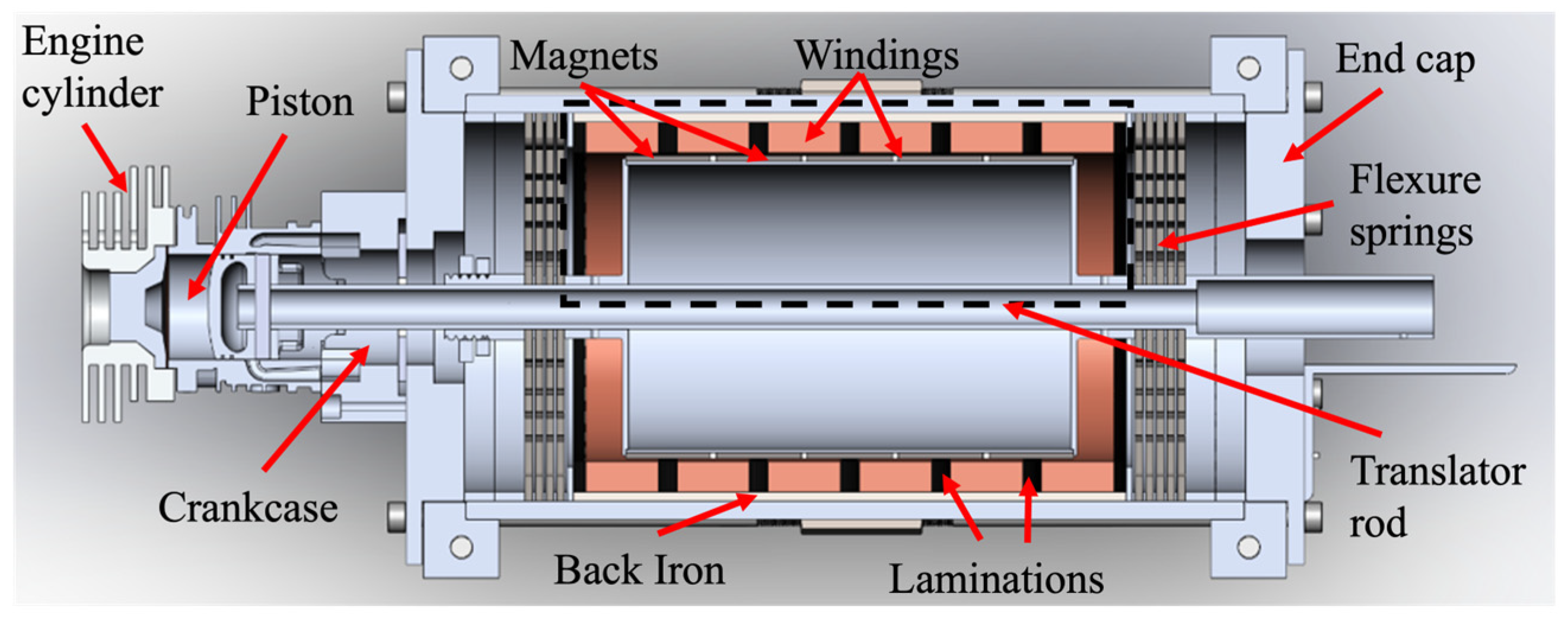
There are three main components of the free piston engine PMLA system developed for this study. They are a two-stroke engine system, a PMLA system, and flexure springs. Figure 6 shows the cross-sectional view of the CAD design of the free piston engine PMLA system.
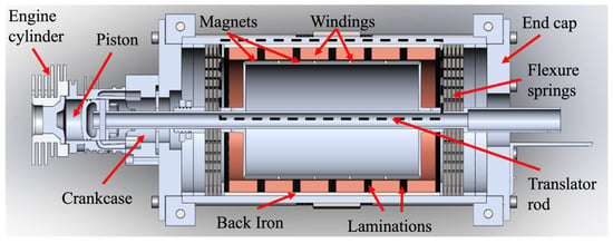
Figure 6.
CAD design of free piston engine PMLA with major components labeled.
6.1. Engine System
The engine system is composed of several key components: (1) a cylinder where combustion occurs, (2) a piston and ring assembly located inside the cylinder, (3) a crankcase, (4) an intake system with port injection, (5) an exhaust system, and (6) a spark plug in the cylinder head for ignition. Since a spark-ignited system is used, the spark plug is positioned on the cylinder head, with timing controlled by a phase-locked loop (PLL) controller. Because the engine operates on a two-stroke cycle, the intake air is mixed with injected gas and enters the crankcase. During the first cycle, the charge within the crankcase is compressed and then enters the cylinder as the piston passes the intake port. In the second cycle, the charge is further compressed and combustion occurs, imparting work on the translator and expelling exhaust once the piston clears the exhaust port.
The two-stroke engine used in this study was based on a commercially available 50 cc engine. The associated piston was modified to accept the translator rod with a custom-made pin. The piston retained rotational degrees of freedom about the pin and was able to translate along the pin’s axis. This modification was necessary to accommodate the position of the crankcase and the tubular body. A custom crankcase base was fabricated with a built-in seal, which mated with the translator rod to maintain positive crankcase pressure. This design allowed the crankcase and two-stroke operation of the engine to function similarly to the original manufacturer’s application.
6.2. PMLA System
The PMLA system consists of a stator and a rotor arranged in a linear configuration. The stator is composed of copper windings, laminated steel, and a back iron core. The translator, or moving component, includes axial flux permanent magnets (N35), an aluminum drum, and a translator rod. The PMLA system operates as a motor during the engine starting phase and as a generator during power generation.
6.3. Springs
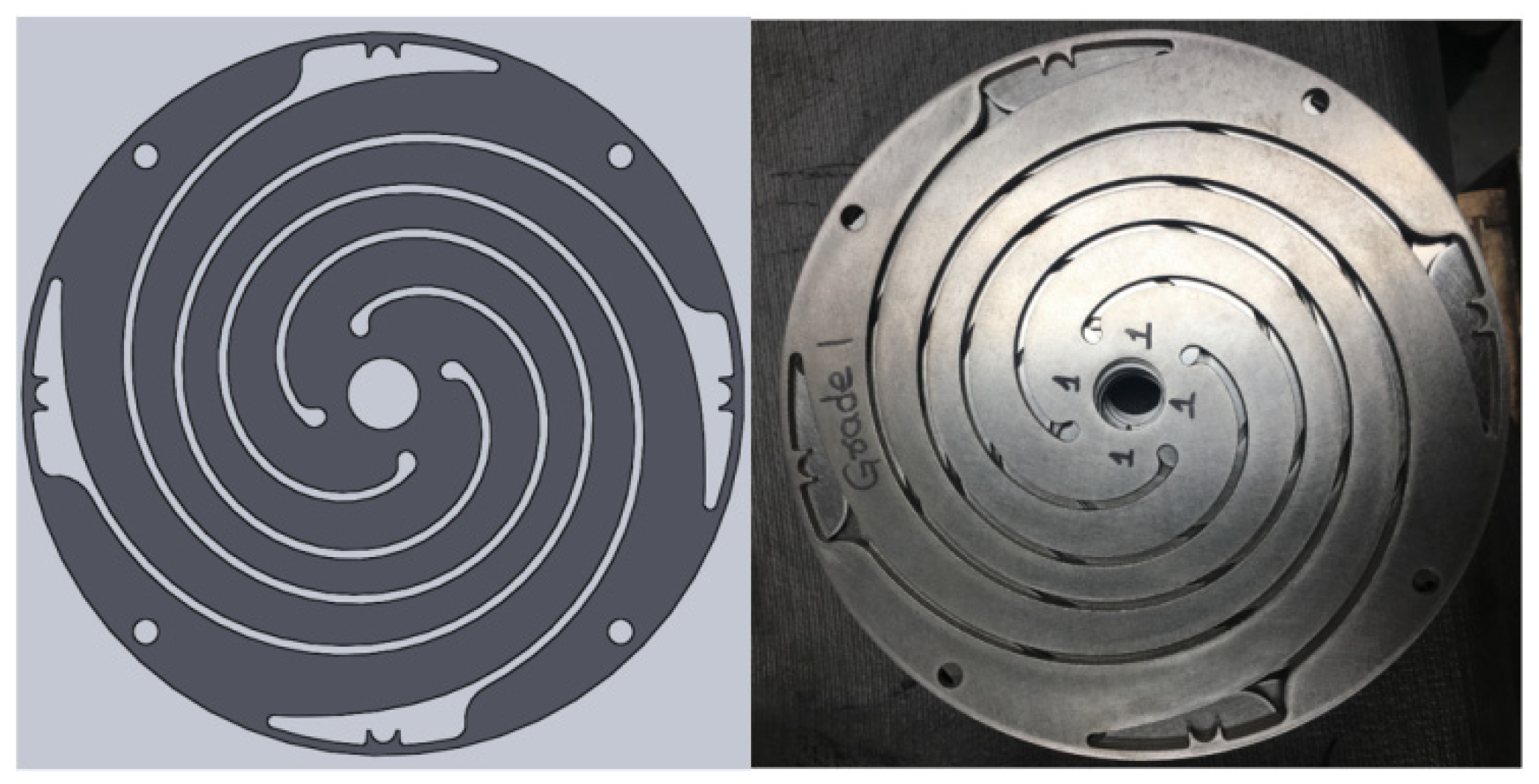
The flexure springs used in the system are a critical component, providing both high-frequency resonance for the linear machine and radial (bearing) support. These flexures are a replacement for the bounce chamber used in designs by others. The final flexure spring design is shown in Figure 7. Sandvik 7C27Mo2 was chosen as the spring material, with the springs manufactured using a waterjet cutting process followed by a secondary surface treatment to enhance fatigue performance. The flexure springs are mounted on either side of the PMLA system, as shown in Figure 6.
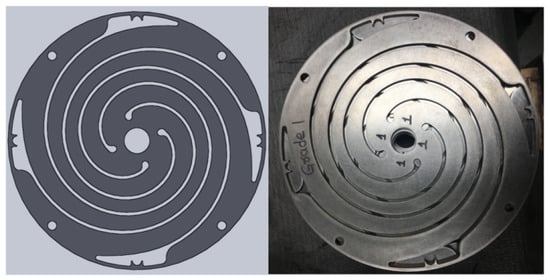
Figure 7.
Geometric design of flexure springs that are manufactured using a waterjet manufacturing process out of sheet stock of Sandvik 7C27Mo2 stainless steel. The flexure undergoes a surface treatment involving shot peening and polishing to improve fatigue life.
The springs serve two primary functions in the PMLA system. First, they act as bearings to maintain the air gap between the stator and translator by being positioned on each side of the translator. Second, they serve as an energy storage system, providing the return force for the alternator during the combustion process. The required number of springs was determined using the two-stroke engine model described earlier, ensuring the spring force meets the operational requirements.
6.4. Flexure Spring Optimization
The optimal design of the spring pattern, shown in Figure 7, was determined using finite element analysis, which included both structural and harmonic analyses. The initial pattern was based on an Archimedes spiral, a design used in previous studies by our group and others [28]. In this application, significant attention was given to optimizing the endpoints of the pattern, where material failure due to fatigue had previously been observed. The flexure springs needed to operate at high working stress to meet the requirements of the PMLA, which made the design process more challenging.
Stainless steel sheet stock produced by Sandvik, specifically 7C27Mo2, was selected as the spring material. This martensitic stainless steel is commonly used in high-cycle fatigue applications, such as butterfly valves. The material was supplied in a heat-treated condition, with the manufacturer reporting a fatigue strength of approximately 780 MPa and a 10% probability of fracture at 107 cycles. The well-defined endurance limit of this material provides confidence that it will last for the intended lifetime of the device.
The springs underwent post-processing that included both mechanical polishing and shot peening. As shown in Figure 7, the resulting surface finish is nearly mirror like. The polishing step was performed to reduce surface imperfections that could serve as crack initiation sites. Shot peening, conducted according to SAE standards, was then applied to introduce compressive stresses at the surface, further improving the fatigue properties of the springs. Despite these processing steps, failures still occurred if the spring shape design did not adequately manage stress concentrations.
It was also observed that increasing the total spring stiffness led to a non-negligible energy loss associated with the springs. This loss, attributed to viscoelastic effects at high frequencies, was found to depend on the peak stress in the material. When the stiffness was increased while maintaining the same stroke, the losses associated with the springs also increased. Although a detailed discussion of this loss mechanism is beyond the scope of this article, it is important to note that the working stress of the springs should be managed to avoid excessive energy loss. Ultimately, in this study, the power density of the design was limited by the fatigue life of the flexure springs.
6.5. Alpha Design
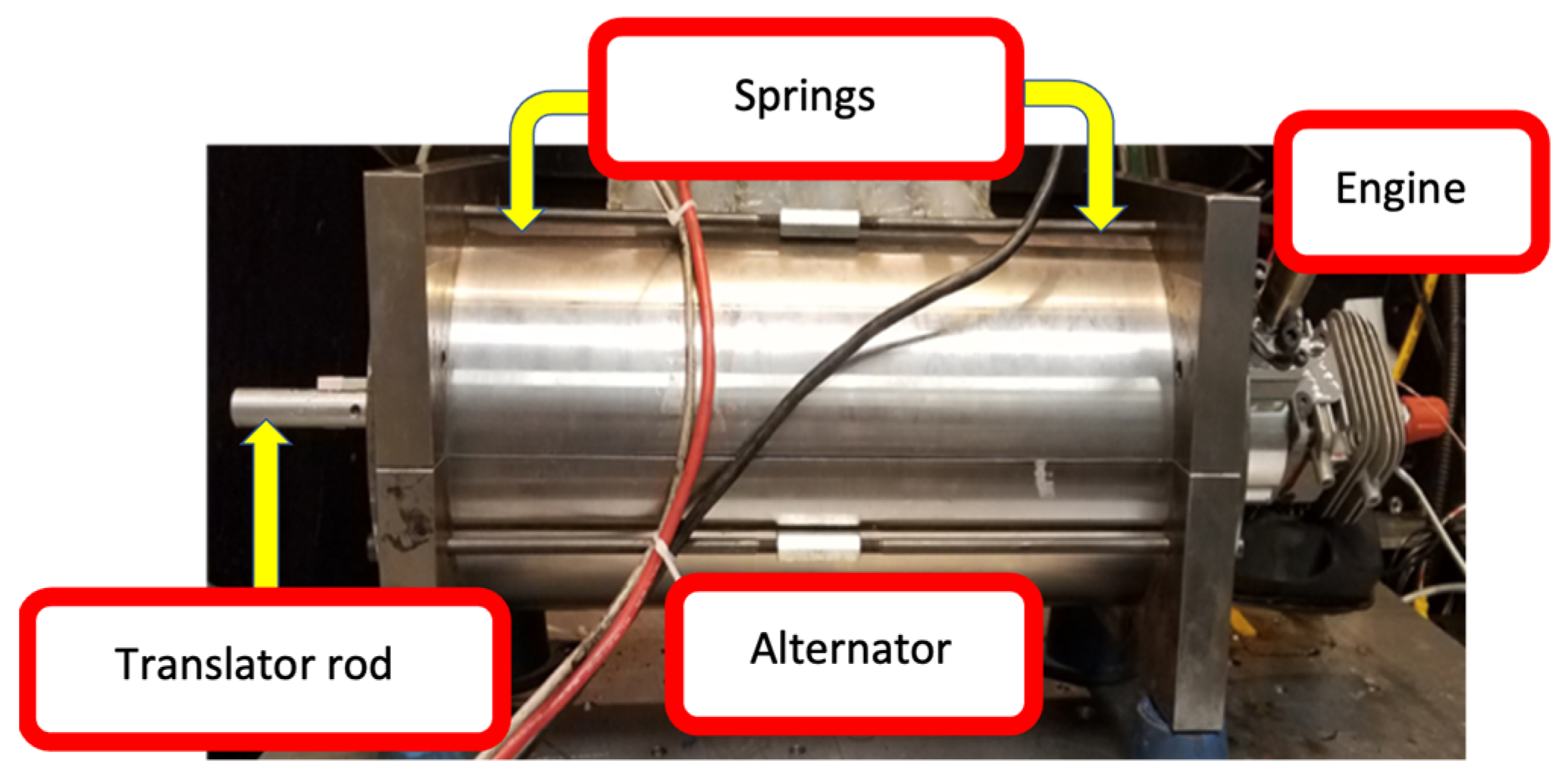
The first generation of the free piston engine PMLA system, built at West Virginia University for this study, was designated the alpha design. Figure 8 is a photo of the alpha design built at WVU.

Figure 8.
The alpha design of the free piston engine PMLA system was the first iterative design that produced positive power.
The geometric parameters of the alpha prototype PMLA system studied are shown in Table 2. The alpha prototype developed was an initial attempt to build a FPLG system targeting a 1 kW output of electric energy. The initial alpha design, with its parameters depicted in Table 2, was simulated by FEMM and SIMULINK models and verified experimentally. The alpha prototype parameters do not directly match with those in Table 1, which are associated with the later beta prototype.
Table 2.
Geometric parameters of the alpha prototype.
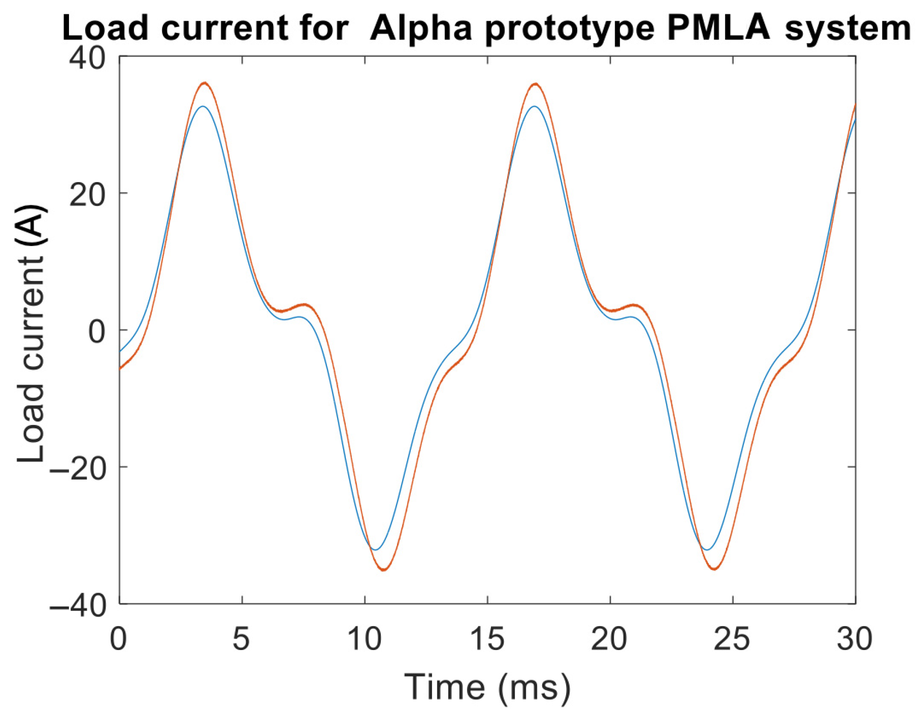
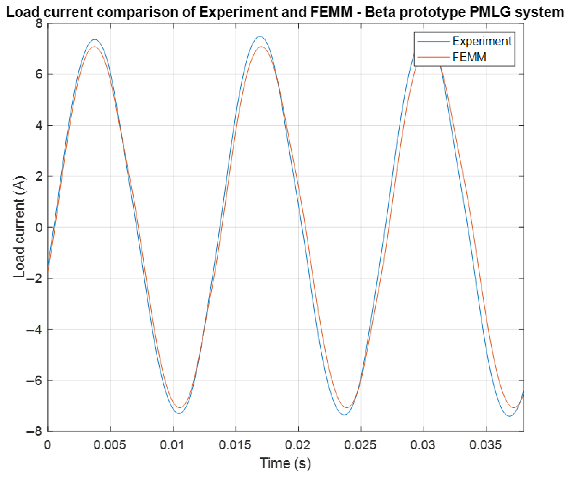
Two different versions of the alpha design were developed. They were air core and iron core versions. The results from the tests are shown below in Table 3 and Table 4 and Figure 9. Figure 9 shows the comparison of experimental and FEMM for a load of 0.094 Ώ and power of 63.2 W (experiment) and 49 W (FEMM) at 25.9 A (experiment) and 22.8 A (FEMM).
Table 3.
Comparison of the experimental tests with FEMM for the air core alpha prototype.
Table 4.
Comparison of the experimental tests with FEMM for the iron core alpha prototype.
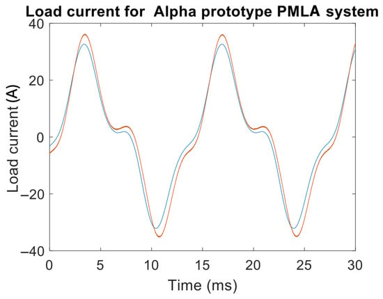
Figure 9.
Load current comparison between experiment (blue) and FEMM (red) for the iron core alpha prototype.
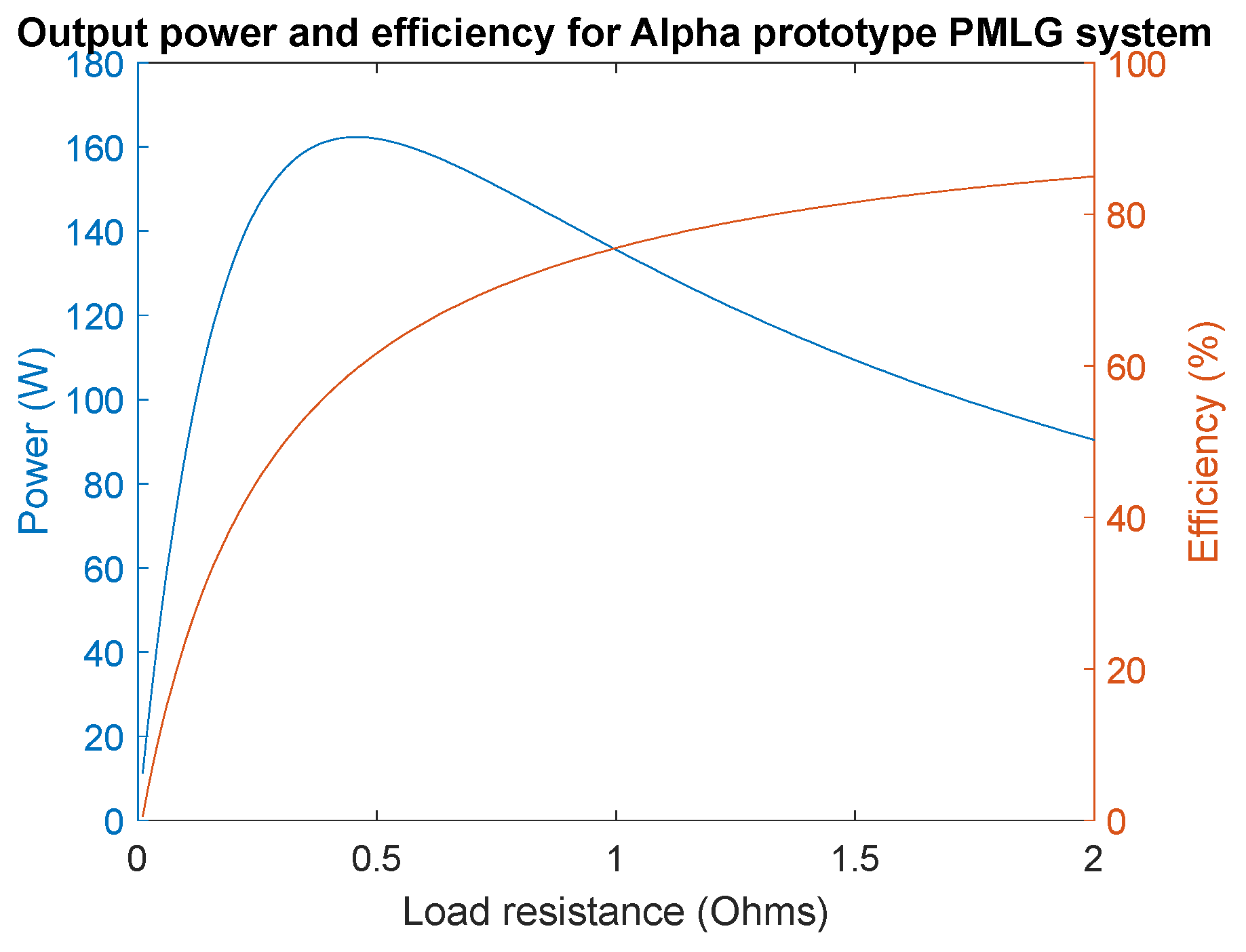
Output power and efficiency for the iron core alpha prototype are shown in Figure 10. Further, the whole power curve was plotted by changing the load from 0 Ώ to 2 Ώ in steps of 0.11 Ώ in FEMM. It can be seen that maximum power up to 163 W at 50% efficiency can be generated from the designed linear alternator. To improve the design and increase the output power, the beta design was developed and is discussed in the next section.
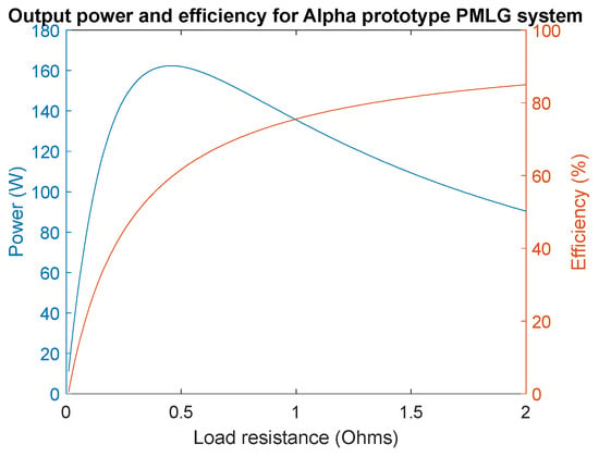
Figure 10.
Output power (blue) and efficiency (red) for the iron core alpha prototype PMLA system. This design achieved a peak power of 163 W at 50% efficiency.
6.6. Beta Design
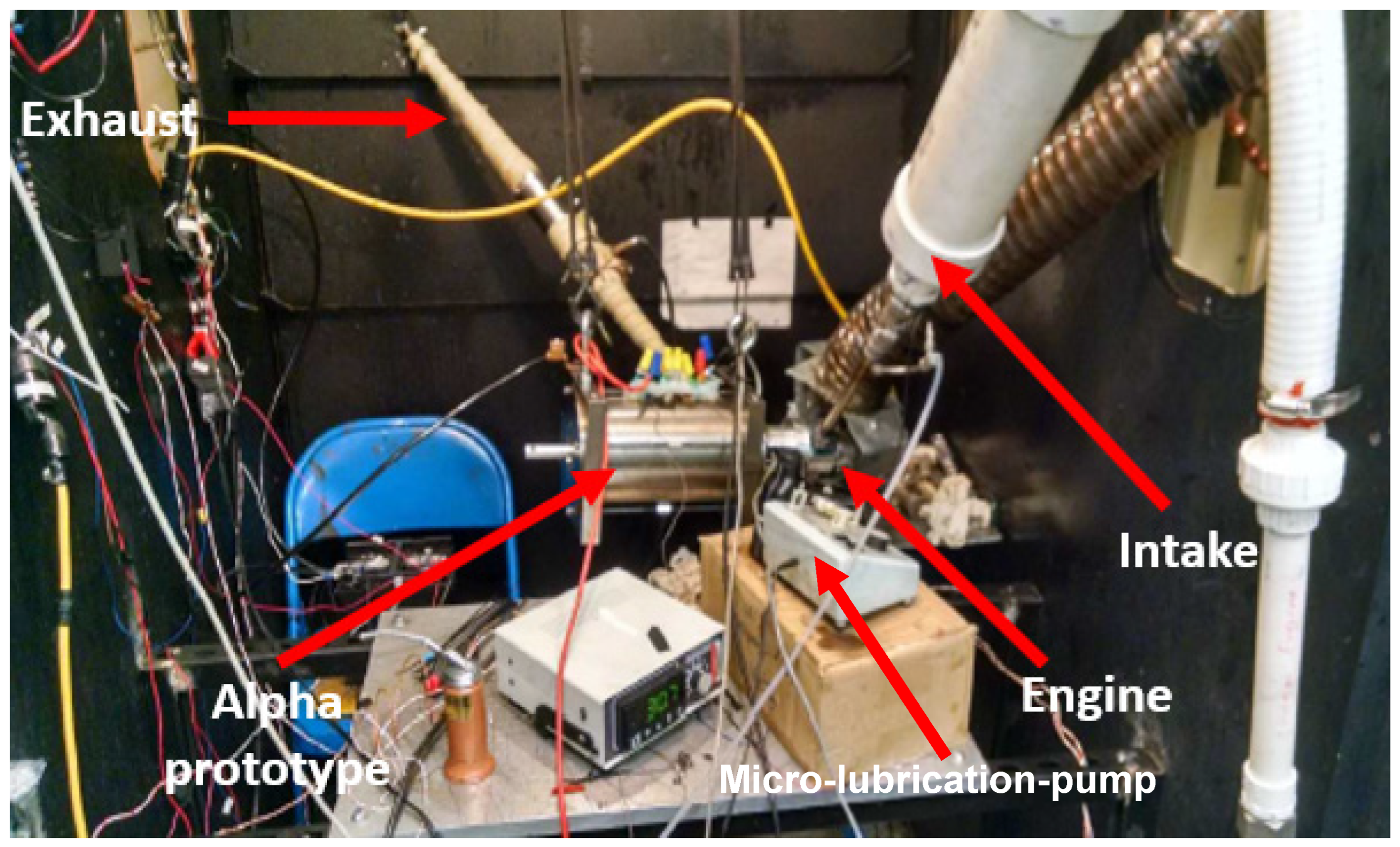
The second generation of the free piston engine PMLA system built for this study was called the beta design. Figure 11 is a photo of the beta design built at WVU. This next iteration involved a redesign of the LA to accompany a two-stroke engine with a larger stroke to increase the overall output power. The stroke length was increased by nearly 11 mm, but the frequency of operation was maintained at 80 Hz. A detailed figure with instrumentation is shown in Figure 12.

Figure 11.
Beta design of the free piston engine PMLA system with a redesign with increased stroke length and alternator design.
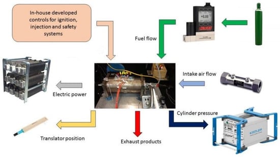
Figure 12.
Complete instrumentation setup for the beta prototype. The two-stroke engine was operated using natural gas.
The geometric parameters of the beta design PMLA system studied are shown in Table 5. Additionally, an illustration of the complete instrumentation used during the operation of the beta prototype is provided in Figure 12. As shown in the figure, the natural gas fuel was precisely controlled. An in-house phase-lock loop controller was used to control the ignition based on the translator position sensor.
Table 5.
Geometric parameters of the beta prototype.
The results from the test of the beta design are provided in Table 6 with a comparison to the FEMM model. Notice there is a nearly doubling of the output power when compared to the alpha design.
Table 6.
Error between FEMM and experiment for 338 W test condition.
From Figure 13, the instantaneous load current versus time the waveform response has been significantly improved when compared to the alpha design waveform. The FEMM results are in good agreement with the experimental results. Table 6 summarizes the error percentage between FEMM and the experiment for load voltage, current, and output power. The voltage error was 3.4%, the current error was 5.2%, and the output error power was 5.9%. The overall error was less than 6% for the voltage, current, and power.
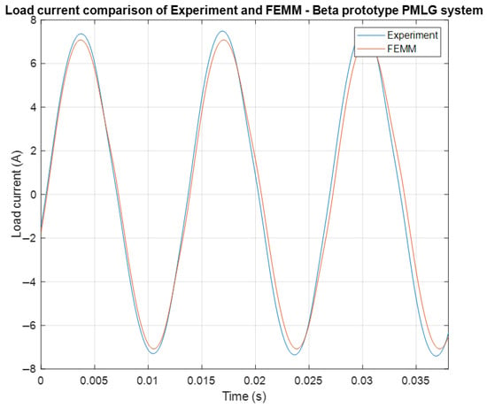
Figure 13.
Load current comparison between the experiment and FEMM for the beta prototype. Approximately 340 watts of electrical power were generated from natural gas two-stroke operation.
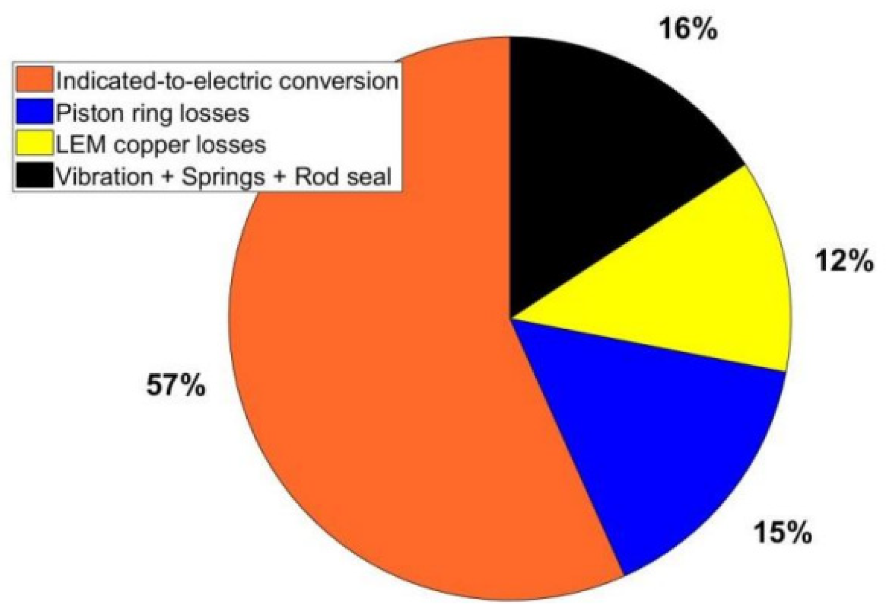
Using capacitors (shown in Figure 12) for compensation for the inductive reactance from the windings of the PMLA, the power generated was improved to 550 W. The beta prototype design was able to produce 550 W, with the engine power being 972.5 W. This is shown through the power distribution and losses in Figure 14.

Figure 14.
Power distribution and associated losses between engine power and conversion to electrical power. The experiment was able to realize 550 W of electrical power at 973 W of engine power, equating to approximately 57% efficiency.
Based on the 800 combustion cycles taken using Kistler Data Acquisition, the engine indicated power was found to be 972.5 W. Of that 972.5 W of indicated power, 550 W, or 56.6%, was converted into electrical power. The rest of the indicated power was lost to overcome the permanent magnet linear alternator resistive losses, piston ring losses, vibration losses, and spring losses. The vibration was dissipated into the mounting plate through the external mounts. This has been the maximum power that has been seen from the design through experimental testing with a beta prototype.
7. Conclusions
In this research, we successfully demonstrated the design, optimization, and experimental validation of a tubular permanent magnet linear alternator integrated with a free piston engine system, achieving 550 W at 57% efficiency. Two iterative prototype designs, referred to as the alpha and beta designs, were developed, modeled, and experimentally evaluated. Through detailed finite element simulations and sensitivity analyses, key parameters, such as magnet thickness, coil geometry, air gap, spring stiffness, and stroke length, were optimized to enhance the alternator’s electrical performance. The experimental results closely matched the computational predictions, demonstrating robust performance and validating the effectiveness of the optimization methodology.
The beta prototype, which featured a refined design with increased stroke length and improved power electronics integration, generated up to 550 W of electrical power from a two-stroke combustion process at a reciprocating frequency of 81.3 Hz and a stroke length of 33 mm. This confirms the system’s potential for scalable power generation applications.
Additionally, the development and optimization of specialized flexure springs greatly improved the stability and operational efficiency of the linear system. This proves that the flexure bearings are a better alternative to bounce chambers for achieving higher power densities.
Overall, this study successfully demonstrates tubular permanent magnet linear alternators to be efficient, reliable, and environmentally friendly alternatives to traditional rotary generators. Future work will focus on further scaling the system, improving spring fatigue performance, and integrating advanced control systems to enhance both the power output and efficiency of free piston linear generator technologies.
Author Contributions
Conceptualization, P.F. and N.C.; Methodology, N.C.; Software, J.S. and F.M.-G.; Validation, P.F.; Formal analysis, J.S., M.B. and T.M.; Investigation, F.M.-G., M.B. and T.M.; Data curation, J.S., F.M.-G. and T.M.; Writing—review & editing, P.F.; Visualization, T.M.; Supervision, P.F.; Project administration, P.F.; Funding acquisition, P.F. All authors have read and agreed to the published version of the manuscript.
Funding
This research was funded by the US Department of Energy ARPA-E GENSET program DE-AR0000608.
Data Availability Statement
Data are contained within the article.
Conflicts of Interest
The authors declare no conflicts of interest.
Nomenclature
The following abbreviations are used in this manuscript for electromechanical and geometric quantities:
| Length of the stator | |
| rotor poles | |
| stroke length | |
| Magnetic field intensity | |
| MT | Magnet thickness |
| Average airgap flux density | |
| Permeability of air | |
| Carter’s co-efficient | |
| airgap | |
| Slot factor | |
| Maximum airgap flux density | |
| Energy density | |
| Energy in the airgap | |
| Rated output power | |
| efficiency | |
| rated frequency | |
| Volume of air | |
| Ds | Diameter of the stator |
| λ | flux linkage |
| Outer diameter of the magnet | |
| Inner diameter of the magnet | |
| Number of turns per phase | |
| Open circuit voltage | |
| Winding factor | |
| Number of turns per slot | |
| Rated current | |
| Rated voltage | |
| Area of the slot | |
| Fill factor | |
| Width of the slot | |
| Height of the slot | |
| force due to the in-cylinder pressure | |
| Spring force | |
| Friction force | |
| Restoring force of biased springs | |
| In-cylinder pressure | |
| Piston area | |
| Dynamic compression ratio | |
| rms | Root Mean Squared |
| TDC | Top Dead centre |
| BDC | Bottom Dead center |
| GHG | Green house gases |
| FPEG | Free Piston Engine Generator |
| PMLA | Permanent Magnet Linear Alternator |
| WEC | Wave Energy Converter |
| LA | Linear Alternator |
Appendix A
A sensitive analysis was conducted using DAKOTA software using the analytical two-stroke engine model with the linear alternator discussed in the narrative in Section 3. The Sobol indices provide a method of assessing how much influence the inputs have on the output objectives. They can also indicate whether the input is directly or inversely correlated to the output (negative means inversely). In the figure below the inputs are mass (m), bore (b), stroke max (smax), spring constant (k), spring bias (k_bias), alternator force amplitude (A), and equivalence ratio (eq_ratio). Timing (t_in) and intake boost (boost) were not varied, so their Sobol indices are zero. The objectives are provided above each grouping of indices, for example, compression (ratio) objective, stroke length, frequency, etc.
In Figure A1, the largest Total Sobol indices for the compression ratio is spring bias. Similarly, the stroke length of the largest Sobol index is the spring bias. However, it should be noted that the indices for the bore are also close in value to the spring bias. Note that for the frequency objective, the mass and spring constant have nearly equal Sobol indices as expected.
The sensitivity analysis was also conducted for the total efficiency, stability, and power output. The Sobol indices are provided in Figure A2. Note that the stability of the engine has the largest Sobol indices for the exhaust port location. This indicates that the exhaust port location is important for the stable operation of the two-stroke engine.
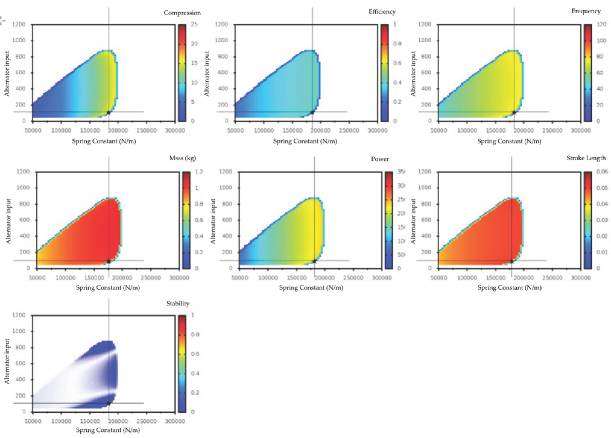
Using the same DAKOTA software and the same model as discussed for the sensitivity analysis, a design space exploration was conducted to find the optimal design to begin the manufacturing process and optimize using experiments. Over a million simulations were run on an HPC computer at WVU to conduct the multi-objective genetic algorithm (MOGA) optimization. In the figure below, the optimal design reported in the report is indicated by the cross-hairs in Figure A3.
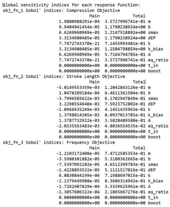
Figure A1.
Sobol indices for compression ratio, stroke length, and frequency.
Figure A1.
Sobol indices for compression ratio, stroke length, and frequency.
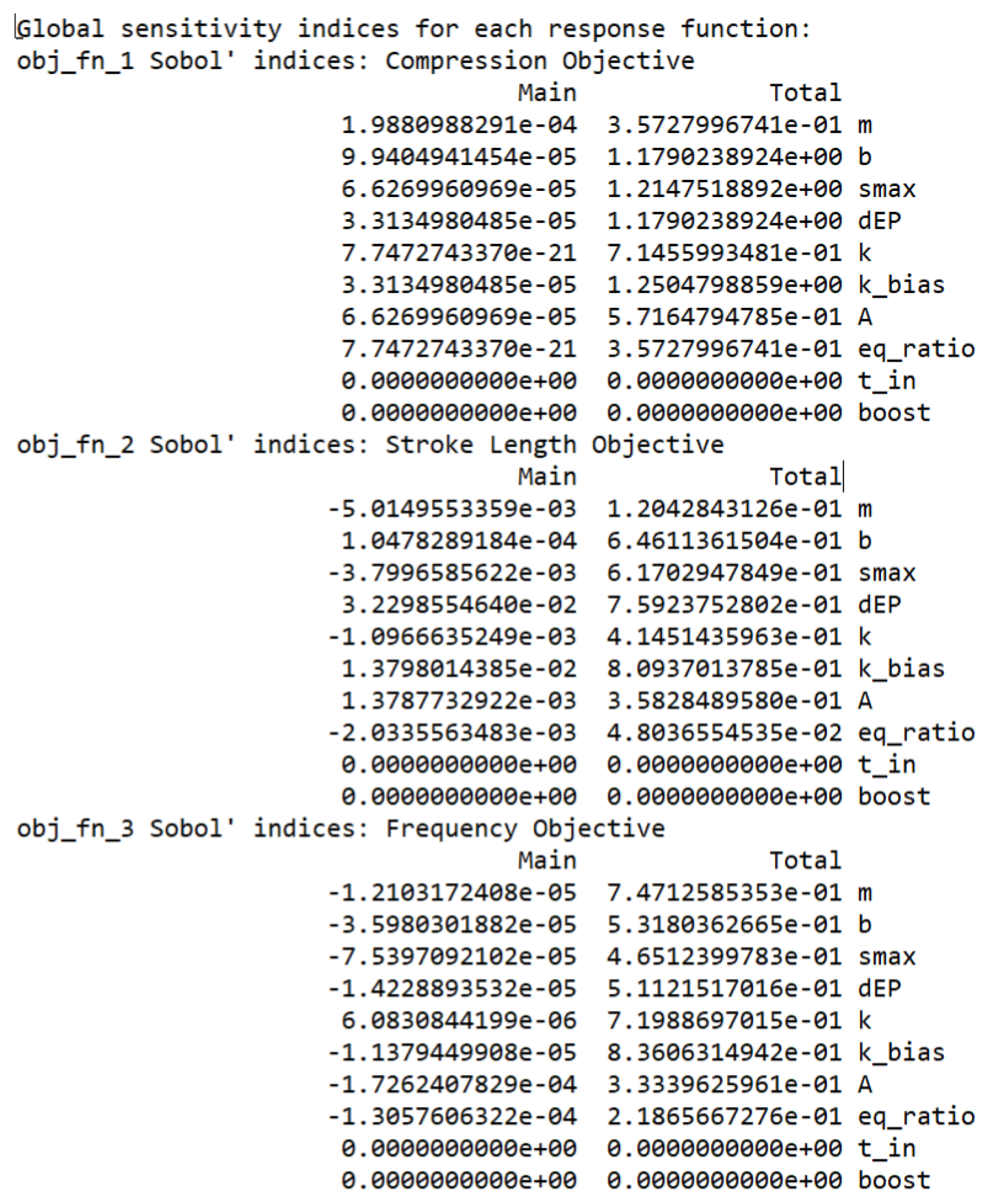
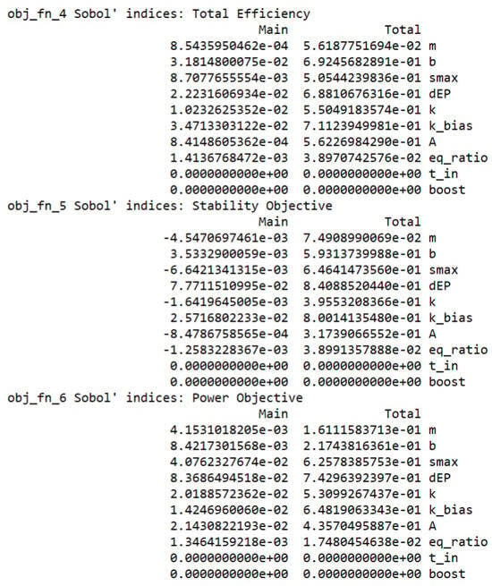
Figure A2.
Sobol indices for total efficiency, stability, and power.
Figure A2.
Sobol indices for total efficiency, stability, and power.
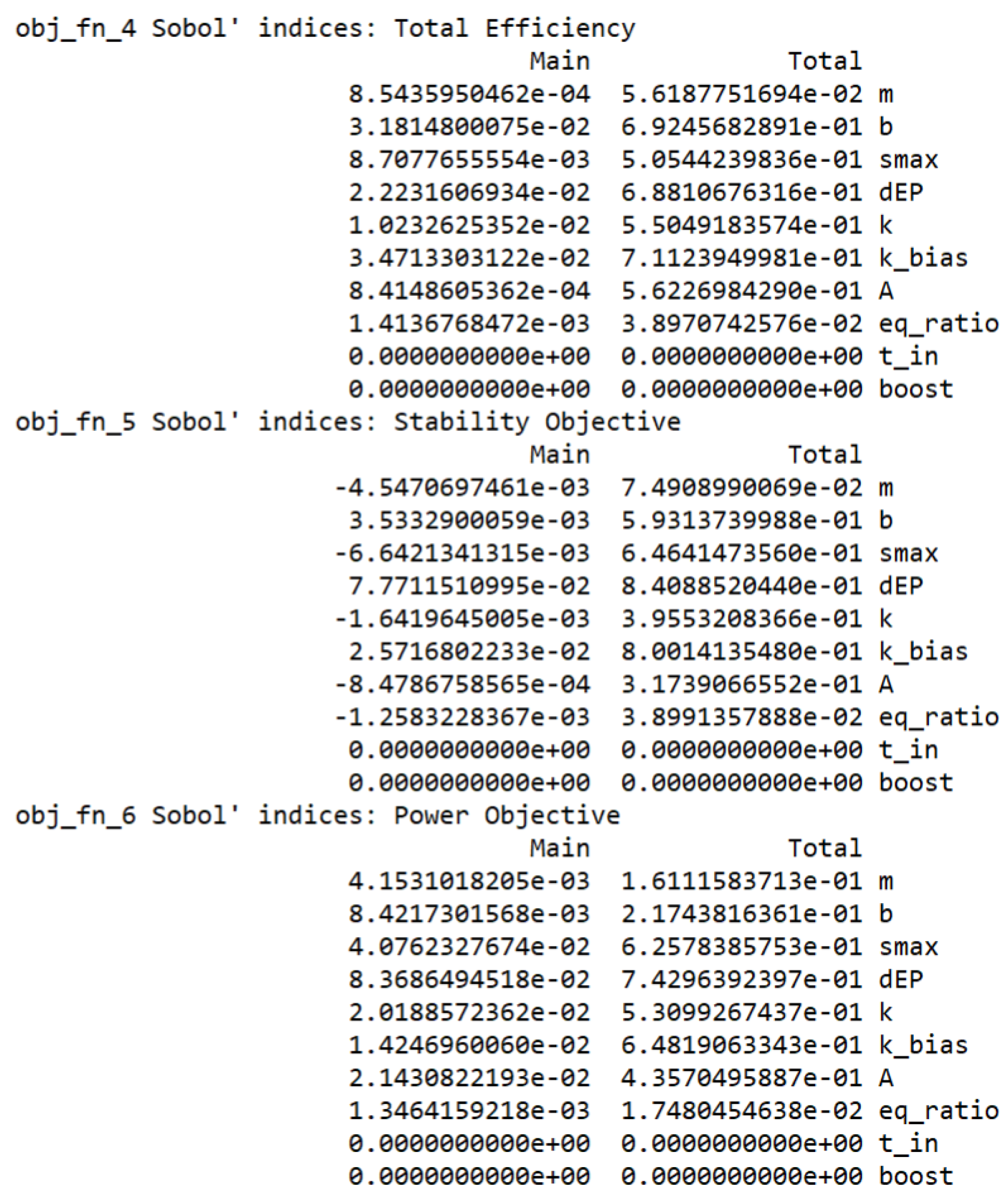
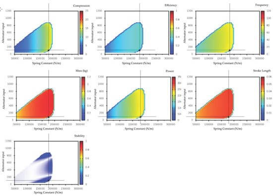
Figure A3.
Data from global optimization study illustrating Pareto fronts for each design variable.
Figure A3.
Data from global optimization study illustrating Pareto fronts for each design variable.
References
- Global Energy Review; Licence: CC BY 4.0; IEA: Paris, France, 2025; Available online: https://www.iea.org/reports/global-energy-review-2025 (accessed on 10 May 2025).
- Holland, R.A.; Scott, K.; Agnolucci, P.; Rapti, C.; Eigenbrod, F.; Taylor, G. The influence of the global electric power system on terrestrial biodiversity. Proc. Natl. Acad. Sci. USA 2019, 116, 26078–26084. [Google Scholar] [CrossRef] [PubMed]
- Akdag, S.; Yıldırım, H. Toward a sustainable mitigation approach of energy efficiency to greenhouse gas emissions in the European countries. Heliyon 2020, 6, e03396. [Google Scholar] [CrossRef] [PubMed]
- Wang, X.; Chen, F.; Zhu, R.; Yang, G.; Zhang, C. A review of the design and control of free-piston linear generator. Energies 2018, 11, 2179. [Google Scholar] [CrossRef]
- Hung, N.B.; Lim, O. A review of free-piston linear engines. Appl. Energy 2016, 178, 78–97. [Google Scholar] [CrossRef]
- Schneider, S.; Chiodi, M.; Friedrich, H.; Bargende, M. Development and experimental investigation of a two-stroke opposed-piston free-piston engine. In Proceedings of the SAE/JSAE 2016 Small Engine Technology Conference & Exhibition, Charleston, SC, USA, 15–17 November 2016. SAE Technical Paper. [Google Scholar]
- Mikalsen, R.; Roskilly, A.P. A review of free-piston engine history and applications. Appl. Therm. Eng. 2007, 27, 2339–2352. [Google Scholar] [CrossRef]
- Washko, F.M.; Winchell, R.A. Free piston combustion engine design analysis and challenges. In Proceedings of the JSAE/SAE 2015 Small Engine Technologies Conference & Exhibition, Osaka, Japan, 26 November 2015. SAE Technical Paper. [Google Scholar]
- Liu, Z.; Wu, Z.; Xu, Y.; Zhang, H.; Zhang, J.; Yang, F. Performance Investigation of Single–Piston Free Piston Expander–Linear Generator with Multi–Parameter Based on Simulation Model. Energies 2022, 15, 9078. [Google Scholar] [CrossRef]
- Ahamed, R.; McKee, K.; Howard, I. A review of the linear generator type of wave energy converters’ power take-off systems. Sustainability 2022, 14, 9936. [Google Scholar] [CrossRef]
- Xu, Z.; Chang, S. Prototype testing and analysis of a novel internal combustion linear generator integrated power system. Appl. Energy 2010, 87, 1342–1348. [Google Scholar] [CrossRef]
- Rinderknecht, F.; Kock, F. A high efficient converter for hybrid vehicle concept. World Electr. Veh. J. 2012, 5, 475–481. [Google Scholar] [CrossRef]
- El-Hami, M.; Glynne-Jones, P.; White, N.M.; Hill, M.; Beeby, S.; James, E.; Ross, J.N. Design and fabrication of a new vibration-based electromechanical power generator. Sens. Actuators A Phys. 2001, 92, 335–342. [Google Scholar] [CrossRef]
- Zhang, Z.; Ma, Y.; Li, M.; Zhao, L. Recent advances of energy recovery expanders in the transcritical CO2 refrigeration cycle. HVAC&R Res. 2013, 19, 376–384. [Google Scholar]
- Zeng, S.; Jing, Y.; Yuan, C. Numerical comparison of HCCI combustion mode between a free piston linear engine and traditional crankshaft engine. J. Therm. Anal. Calorim. 2021, 146, 1359–1369. [Google Scholar] [CrossRef]
- Najt, P.M.; Durrett, R.P.; Gopalakrishnan, V. Opposed Free Piston Linear Alternator. U.S. Patent 112468A1, 10 May 2012. [Google Scholar]
- Hidemasa, K.; Yuichi, O.; Yoshihiro, H.; Kiyomi, N.; Kosuke, A. Free-piston Type Generator. Japan Patent JP2012202385A, 22 October 2012. [Google Scholar]
- Famouri, P.; Cawthorne, W.R.; Clark, N.; Nandkumar, S.; Atkinson, C.; Atkinson, R.; Petreanu, S. Design and testing of a novel linear alternator and engine system for remote electrical power generation. In IEEE Power Engineering Society. 1999 Winter Meeting (Cat. No. 99CH36233); IEEE: New York, NY, USA, 1999; Volume 1, pp. 108–112. [Google Scholar]
- Leick, M.T.; Moses, R.W. Experimental Evaluation of the Free Piston Engine-Linear Alternator (FPLA) (No. SAND2015-2095); Sandia National Lab. (SNL-NM): Albuquerque, NM, USA, 2015. [Google Scholar]
- Boldea, I.; Nasar, S.A. Permanent-magnet linear alternators part 1: Fundamental equations. IEEE Trans. Aerosp. Electron. Syst. 1987, 23, 73–78. [Google Scholar] [CrossRef]
- Boldea, I.; Nasar, S.A. Permanent-Magnet Linear Alternators Part II: Design Guidelines. IEEE Trans. Aerosp. Electron. Syst. 1987, 23, 79–82. [Google Scholar] [CrossRef]
- Boldea, I.; Nasar, S.A. Linear Motion Electromagnetic Devices; Taylor & Francis: Abingdon, UK, 1997. [Google Scholar]
- Subramanian, J.; Famouri, P. Analysis of Neutral position, Magnet—Spacer of Tubular Permanent Magnet Linear generator for FPE applications. In Proceedings of the 2019 IEEE 28th International Symposium on Industrial Electronics (ISIE), Vancouver, BC, Canada, 12–14 June 2019. [Google Scholar]
- Subramanian, J.; Heiskell, G.; Mahmudzadeh, F.; Famouri, P. Study of radial and axial magnets for linear alternator—Free piston engine system. In Proceedings of the 2017 North American Power Symposium (NAPS), Morgantown, WV, USA, 17–19 September 2017; pp. 1–6. [Google Scholar] [CrossRef]
- Subramanian, J.; Mahmudzadeh, F.; Bade, M.; Famouri, P. Simulation and Experimental Validation of Equivalent Circuit Parameters and Core Loss in a Tubular Permanent Magnet Linear Generator for Free Piston Engine Applications. In Proceedings of the 2019 IEEE International Electric Machines & Drives Conference (IEMDC), San Diego, CA, USA, 12–15 May 2019; pp. 57–62. [Google Scholar] [CrossRef]
- Meeker, D. Finite Element Method Magnetics (FEMM). Available online: https://www.femm.info/wiki/HomePage (accessed on 10 May 2025).
- Adams, B.M.; Bohnhoff, W.J.; Dalbey, K.R.; Ebeida, M.S.; Eddy, J.P.; Eldred, M.S.; Winokur, J.G. Dakota, a Multilevel Parallel Object-Oriented Framework for Design Optimization, Parameter Estimation, Uncertainty Quantification, and Sensitivity Analysis: Version 6.13 User’s Manual (No. SAND2020-12495); Sandia National Lab.(SNL-NM): Albuquerque, NM, USA, 2020. [Google Scholar]
- Chen, N.; Chen, X.; Wu, Y.N.; Yang, C.G.; Xu, L. Spiral profile design and parameter analysis of flexure spring. Cryogenics 2006, 46, 409–419. [Google Scholar] [CrossRef]


Disclaimer/Publisher’s Note: The statements, opinions and data contained in all publications are solely those of the individual author(s) and contributor(s) and not of MDPI and/or the editor(s). MDPI and/or the editor(s) disclaim responsibility for any injury to people or property resulting from any ideas, methods, instructions or products referred to in the content. |
© 2025 by the authors. Licensee MDPI, Basel, Switzerland. This article is an open access article distributed under the terms and conditions of the Creative Commons Attribution (CC BY) license (https://creativecommons.org/licenses/by/4.0/).