1. Introduction
There is no universally accepted definition of a robot. However, certain characteristics and qualities can be used to determine whether a device or machine qualifies as a robotic system. A robot must be capable of environmental awareness, mobility, and efficient use of energy resources. When these conditions are met, it is essential that the robot can fulfill the designated operational requirements [
1,
2,
3].
A mobile robot is defined as a system capable of performing tasks in a variety of locations. Unlike fixed-based industrial robots, mobile robots are characterized by their inherent ability to move freely within the limits of their physical dimensions [
4,
5,
6]. Mobile robots have been shown to perform a wide range of tasks [
7], which can be categorized into several domains, including surveillance, reconnaissance, patrolling, firefighting, search and rescue, maintenance, and entertainment [
8,
9,
10,
11].
In modern society, collaboration between mobile robotic systems and humans in performing daily tasks has become increasingly expected. To enable such integration, robotic systems must possess certain key features, which include [
12]:
Long operational lifespan;
High efficiency in task execution;
Cognitive capabilities to accurately interpret human intent;
Extended operation without the need for recharging;
Reliable performance under varying environmental conditions;
Environmental safety and versatility across multiple application domains.
The motion unit of a mobile robotic system is highly dependent on the intended operational environment, which can generally be categorized into three domains: aerial, aquatic, and terrestrial. Propellers and screws are typically more effective in aquatic and aerial environments, while wheels, tracks, legs, or their combinations are more suitable for terrestrial conditions [
13,
14,
15].
The choice of locomotion mechanism and its integration into the mobile robotic system is critical for ensuring effective performance. These choices directly affect the system’s power requirements. For example, wheeled systems often offer advantages in terms of speed and energy efficiency. In contrast, tracked systems are generally more capable of navigating uneven terrain and overcoming obstacles, though they tend to be less efficient in terms of velocity and energy consumption [
16,
17].
To accurately determine the power requirements and energy consumption of mobile robotic systems, several additional factors must be considered [
12], including:
Required speed and torque;
Energy-consuming components such as sensors, communication modules, and controllers;
Irregularities and obstacles in the operational environment;
The total weight of the mechanical structure and its payload.
Energy efficiency is central to modern engineering design. Recent studies use machine learning approaches to cut both energy use and latency; for instance, Yıldız and Sokullu [
18] reduced end-to-end delay in multi-server MEC systems with a deep-Q-learning load-balancing scheme under heterogeneous traffic.
A key consideration in the design of robotic systems is reducing structural weight while maintaining mechanical strength, with the aim of improving both energy and operational efficiency—particularly given the limited energy resources available to such systems [
19]. Weight reduction is critically important, as it enables the use of more efficient and economical energy sources, thereby lowering the total system weight. This contributes significantly to the sustainability and functional effectiveness of mobile robotic platforms.
Several techniques have been proposed to achieve this goal. A commonly adopted strategy is the use of lightweight materials, such as replacing structural steel with aluminum alloys in frame and chassis design. Modular architectures have also been shown to improve energy efficiency by increasing system adaptability. These designs allow for easy integration or removal of components—such as distance sensors and RGB cameras—based on task-specific requirements, enhancing the robot’s versatility.
Another effective strategy is topology optimization (TO), an advanced structural design methodology that enables the creation of lightweight, high-performance configurations that are often unattainable through conventional design methods [
20,
21]. TO achieves optimal material distribution to satisfy specific load conditions, performance criteria, and design constraints [
22]. It has been widely applied in fields such as automotive, robotics, and aerospace for the development of sustainable and energy-efficient components [
23].
Various TO methods have been introduced in the literature. Among the most used in commercial engineering software are the Solid Isotropic Material with Penalization (SIMP) and Evolutionary Structural Optimization (ESO) techniques [
23,
24,
25]. Notably, TO is closely associated with additive manufacturing (AM), as AM enables the realization of complex, high-performance structures that are difficult to produce using traditional methods. Conversely, TO facilitates the design of components specifically optimized for AM processes. The integration of TO and AM provides a robust framework for aligning structural design with manufacturing capabilities, fostering innovation in lightweight engineering [
23].
In robotic system design studies, the use of topology optimization (TO), additive manufacturing (AM), and their integration have been widely adopted to enhance operational efficiency and reduce energy consumption. Sha et al. [
26] proposed a TO-based methodology aimed at minimizing robot weight without compromising structural integrity. This approach used finite element analysis (FEA) of the assembly to evaluate stress and deformation, followed by redesigning components to minimize mass and limit maximum displacement. The methodology was applied to an upper-limb exoskeleton robot with five degrees of freedom, resulting in a 10.4% reduction in mass compared to conventional designs.
Huang et al. [
27] focused on the TO design of a lightweight, integrated manifold with reduced pressure loss for a hydraulic quadruped robot actuator. Their work addressed both structural design and print quality improvement. The optimized manifold achieved a 50.7% volume reduction while maintaining mechanical performance.
Sun et al. [
28] introduced a TO-based multi-objective design approach for compliant robotic legs. By balancing structural stiffness and bending flexibility, they enabled stable and continuous straight-line walking in a quadruped robot, which was validated through experimental testing.
Padilla-García et al. [
29] developed a multi-configurable omnidirectional mobile robotic platform using a sequential mechatronic design-control process. The structure was prototyped using AM techniques, highlighting the role of rapid prototyping in robotic system design.
Arat et al. [
30] examined the structural performance of a pneumatic gripper designed for handling 500 kg automotive parts. Through TO, the gripper’s mass was reduced by 35%, accompanied by a moderate increase in stress and a reduction in the safety factor to 4.72. Despite these changes, structural integrity was preserved, demonstrating the effectiveness of TO in achieving weight reduction while maintaining functional performance.
Graph-based algorithms, such as Dijkstra’s and A*, are widely used in mobile robot path planning due to their resolution completeness and optimality assuring optimal solutions within discretized environments [
31]. However, their scalability is limited in high-dimensional spaces due to the computational cost of constructing full occupancy grids. To address this, sampling-based methods like Rapidly Exploring Random Trees (RRTs) have been developed. These approaches efficiently explore complex, high-dimensional spaces by incrementally building search trees through random sampling, though they lack guarantees on solution optimality [
9,
32]. Karaman and Frazzoli [
33,
34] developed RRT* for asymptotic optimality via path rewiring. Informed RRT* improves convergence by sampling only in promising regions. Gammell et al. [
34] extended this with BIT*, using A*-like heuristics on sample batches. However, in complex spaces, suboptimal initial paths can enlarge the informed set and reduce efficiency [
9].
Path planning remains a critical challenge in mobile robotics, particularly when balancing multiple objectives such as energy efficiency, trajectory smoothness, and obstacle avoidance. Traditional deterministic methods like A*, Dijkstra’s algorithm, and their multi-objective extensions (e.g., weighted A*) offer high explainability and real-time feasibility. However, they may underperform in highly dynamic or partially observable environments.
To overcome these limitations, recent studies have explored both biologically inspired and learning-based strategies. For example, Chen [
35] introduced an optimized foothold planning algorithm for quadruped locomotion in energy-demanding terrain scenarios using posture adaptation and dynamic stability criteria. Raj and Kos [
36] applied an intelligent particle swarm optimization (PSO) framework to minimize both energy and time in mobile robot navigation, demonstrating significant gains in energy efficiency across different path configurations. Chen et al. [
37] proposed a hybrid meta-heuristic approach using Cuckoo–Beetle Swarm Search for heterogeneous mobile robots, showing robustness under variable terrain and payload conditions. Additionally, Chen et al. [
38] introduced a RL-based energy-saving path planning algorithm (ESPP-RL) tailored for UAVs navigating turbulent wind environments. Their approach dynamically adapts to wind-induced disturbances via a custom reward function, achieving notable reductions in energy consumption and improved robustness in 3D simulation trials. Moreover, Ahmad Khan et al. [
39] developed a RL-driven ankle rehabilitation robot trajectory planner that integrates EMG feedback and joint reaction forces to generate energy-efficient, physiologically adaptive paths for stroke patients, demonstrating the transferability of energy-aware RL planning to systems with high human-interaction constraints.
These emerging approaches highlight the growing trend toward data-driven or hybrid planners in robotic mobility systems. In contrast, this current study retains deterministic planning but combines it with a learning-based terrain energy model and structural topology optimization to enable lightweight, energy-aware path execution with high real-time reliability.
In this study, a mobile robotic system was designed and developed with an emphasis on structural and energy efficiency. Topology optimization was applied to the initial design to reduce weight and enhance both operational and energy performance. The structural integrity of the optimized design was validated using finite element analysis (FEA).
The mechanical components of the robotic system, including frame parts and hardware mounting elements, were fabricated using ABS (Acrylonitrile Butadiene Styrene) material through Fused Deposition Modeling (FDM), a widely used additive manufacturing (AM) technique. Additionally, a custom power analysis tool was developed to compare the energy performance of the optimized structure with the original design.
The system was equipped with key hardware components: a Raspberry Pi 4B as the main controller, an RGB camera for environmental perception, a LiPo battery as the main power source, DC motors with motor drivers for mobility, a power bank for auxiliary power to the Raspberry Pi, and a current sensor for real-time energy monitoring.
A comprehensive dataset was collected, including current measurements from various real-world terrains such as flat surfaces, inclined paths, low-height obstacles causing vibration, gravel surfaces, and sections requiring directional changes to navigate around obstacles. Using these current draw data, a machine learning-based path planning framework was proposed. This model identifies the optimal path by simultaneously considering both energy consumption and distance, rather than treating them independently, with the objective of reaching a predefined target.
The performance of the proposed path planning method was analyzed and validated. Traditional path planning approaches for mobile robots primarily aim to minimize path length between the initial and goal configurations. However, studies in the literature generally focus either on minimizing path cost (i.e., distance) or on minimizing energy consumption. In contrast, this study presents a novel framework that integrates both criteria—energy efficiency and path length—using machine learning techniques to determine the optimal path toward a defined target.
Real-world motion data were collected to build an energy-efficient path planning model, rather than relying solely on theoretical simulations. These data encompass diverse terrain conditions, including flat ground, slopes, vibration-inducing elevation changes, gravel, and path segments requiring directional shifts. During traversal, current consumption was recorded to construct a detailed dataset.
While previous studies have combined machine learning with RRT* or GA-based path planners, such frameworks generally focus on navigation or trajectory efficiency without integrating structural characteristics of the robot. In contrast, our framework tightly couples topology optimization (TO) and machine learning (ML) to enable mutual reinforcement between structural design and energy-aware path planning. This integration allows terrain-dependent energy consumption predictions to guide the path planner, while structural optimization ensures that the resulting mechanical design remains lightweight and efficient under realistic operating conditions—an approach not explored in earlier TO-only or ML-enhanced RRT* pipelines. Furthermore, our solution emphasizes real-time applicability using an XGBoost-powered Weighted A* planner, offering advantages over GA-based approaches that often suffer from high computation latency and limited embedded integrability.
The mobile robot used in this study was structurally optimized via topology optimization to reduce weight while ensuring sufficient mechanical strength. It was manufactured using modern additive manufacturing technologies. Overall, this framework contributes to the literature in the domains of energy-efficient design, sustainable robotics, and advanced path planning strategies.
The remainder of this paper is organized as follows:
Section 2 describes system design, data collection, topology optimization, and model development.
Section 3 presents the experimental results and discussion. Finally,
Section 4 concludes the study and outlines future directions.
2. Materials and Methods
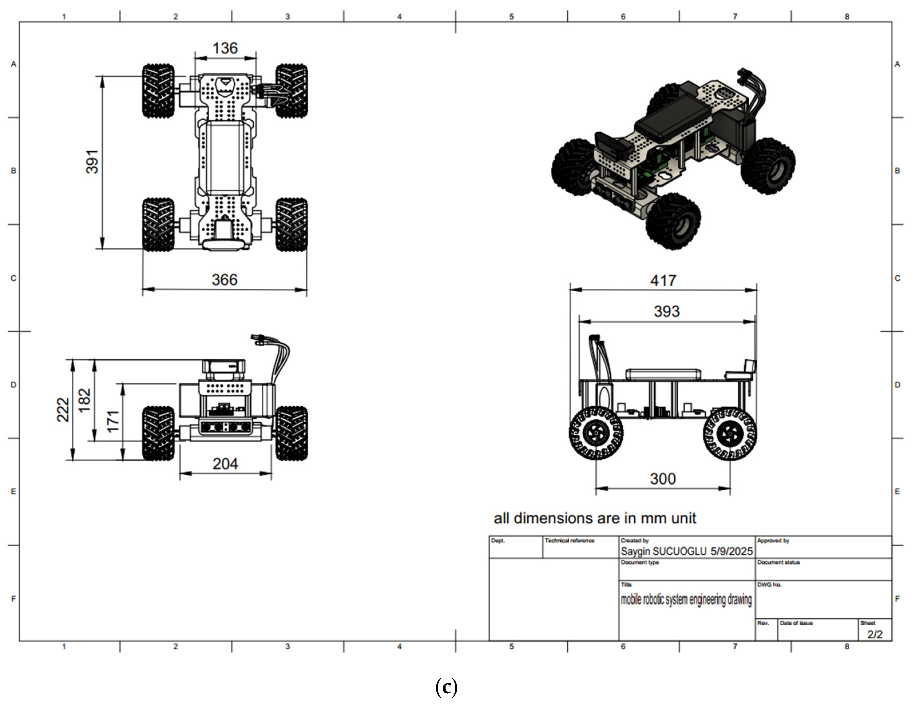
2.1. Structure Design of Mobile Robotic System
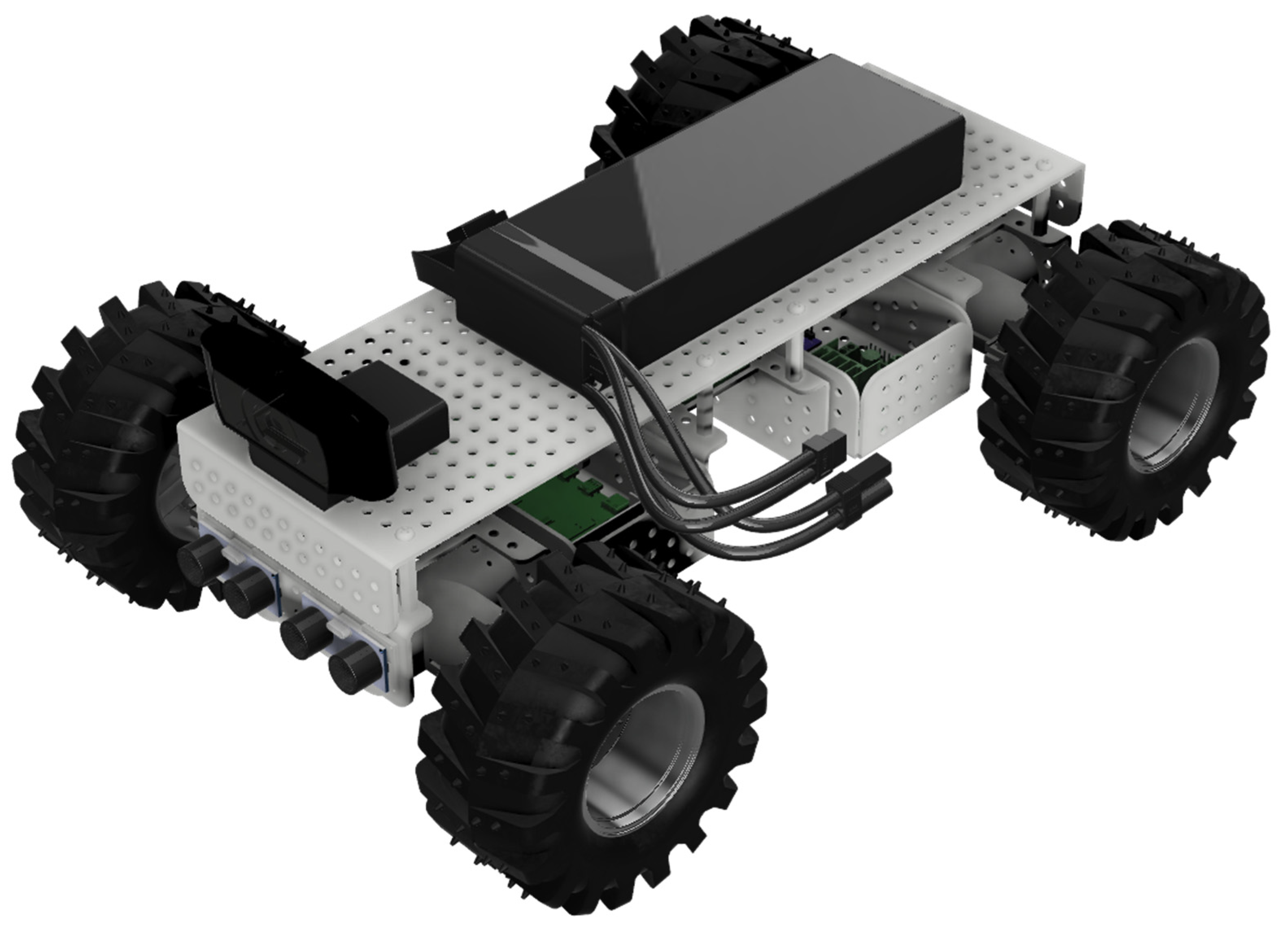
The parametric solid modeling of the mobile robotic system was conducted using Fusion 360 (v.2603.1.15) software. In the initial stage, the primary structural components, namely the main frames and support elements, were designed. Mounting regions and connection holes were integrated into the overall assembly model.
Following this, the selected hardware elements and their corresponding mounting parts were incorporated, resulting in the creation of a non-optimized structural assembly. The placement and configuration of these hardware components were critical design considerations, as their weights were included in the finite element analysis (FEA), and the mounting areas were designated as excluded zones in the subsequent topology optimization process.
The assembly model of the non-optimized mobile robotic structure is presented in
Figure 1.
A series of engineering analyses were performed on the primary structure to assess the system’s structural integrity and stability. These analyses were conducted using finite element analysis (FEA), primarily to evaluate the feasibility of applying topology optimization. The frame material was specified as ABS (Acrylonitrile Butadiene Styrene) plastic. The mechanical properties of ABS are provided in
Table 1.
Loads were applied to evaluate the resulting stress distributions and safety factors. The engineering analyses were conducted in the Static Structural Environment of Ansys Workbench 2024. Separate analysis sets were created for the upper and lower frame components. The analysis configurations for both frame sections are illustrated in
Figure 2.
The frame material was defined as ABS plastic. A vertical load of 20 N and 0.2 Nm was applied to the upper and lower frames, respectively, simulating the effects of hardware weight and motor-generated torque. A detailed evaluation of the analysis results was conducted to assess the necessity of applying topology optimization.
Mesh generation was carried out using second-order tetrahedral SOLID187 elements due to their suitability for capturing complex geometries and stress gradients. A patch-conforming meshing technique was applied. Mesh quality metrics were verified with minimum element quality > 0.75, aspect ratio < 3, and skewness < 0.25. Critical stress zones such as bolt holes and filleted corners were refined with local mesh controls to ensure solution accuracy. A convergence study was conducted by gradually refining the mesh until the variation in maximum von Mises stress between consecutive runs dropped below 2%. The force convergence criterion was set to 1 × 10⁻³ to ensure stable and reliable simulation results.
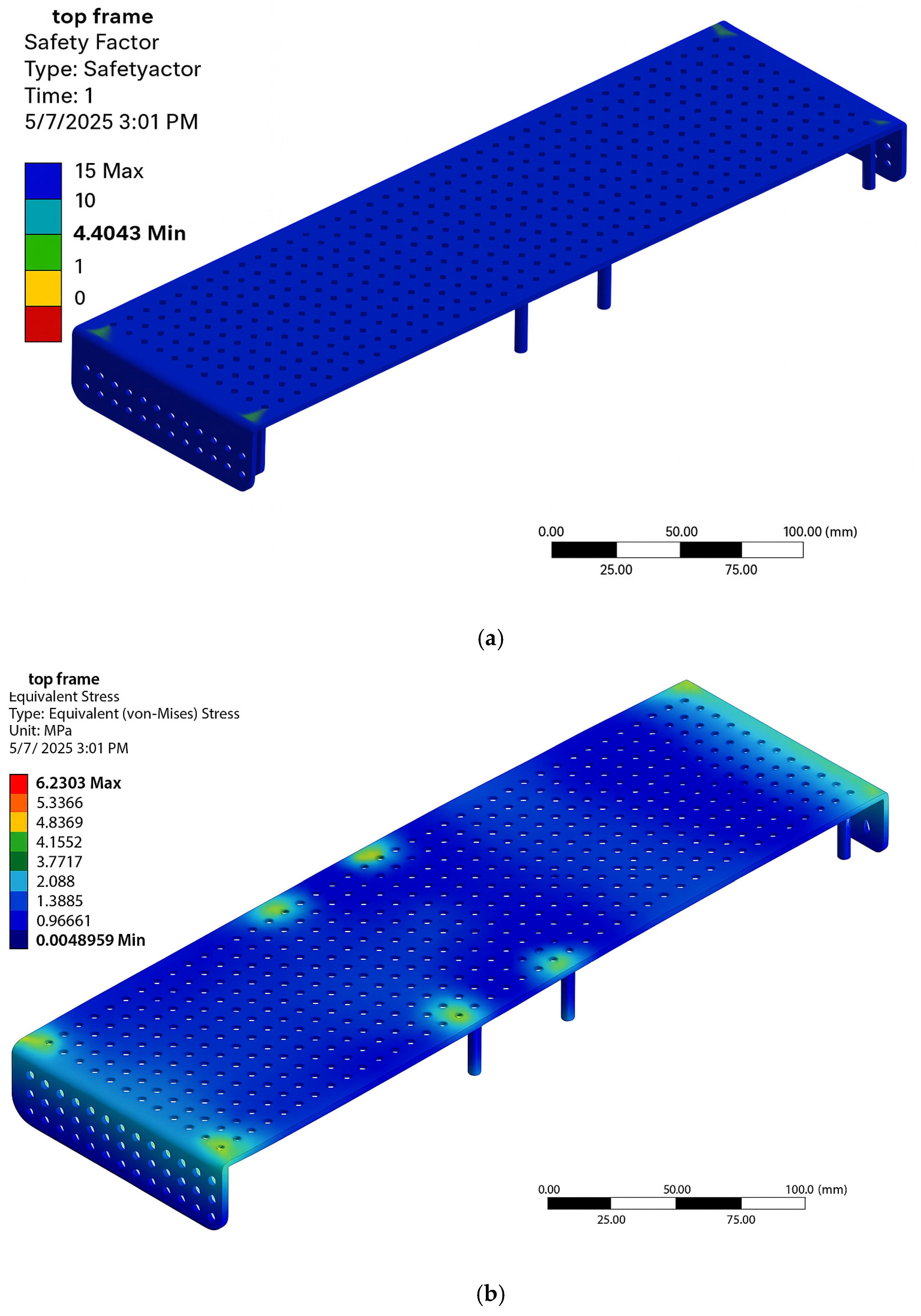
Preliminary structural calculations indicated that at a thickness of 3 mm, the upper and lower frames weighed approximately 150 g and 305 g, respectively. The calculated safety factors were 4.4 for the upper frame and 2.4 for the lower frame—both exceeding standard structural safety requirements. The corresponding von Mises stress values were approximately 6.2 MPa and 11.3 MPa.
These results confirmed the feasibility of applying topology optimization to reduce structural weight and enhance the system’s energy efficiency. The safety factor and von Mises stress distributions for the upper frame are shown in
Figure 3.
2.2. Topology Optimization Procedure
The topology optimization process was carried out using the Ansys topology optimization tool, which employs the Solid Isotropic Material with Penalization (SIMP) method. Throughout the iterative process, the solver adjusts the material density (
) within the designable region, ranging from 0 to 1, excluding the protected zones. A density value of
= 1 corresponds to solid material, while
= 0 indicates the complete removal of material in that region [
36].
The optimization was based on topology density, with a threshold value set at 50%. Connection zones were designated as excluded regions to preserve structural integrity during the optimization.
Optimized structural configurations were obtained through multiple iterative simulations. Based on the resulting data and output design files, new top and bottom frame models were generated. The weights of the optimized top and bottom frames were calculated as approximately 125 g and 170 g, respectively. The resulting optimized frame geometries are presented in
Figure 4.
The optimization objective was to minimize structural compliance under the applied loading conditions while satisfying the volume constraint. Critical mounting and connector regions were designated as “preserved regions” and excluded from material removal to ensure functional integrity. Each iteration of the SIMP-based solver updated the material density field to converge toward a minimum compliance configuration, and the final output was exported as STL meshes for post-processing and redesign.
To evaluate the mechanical performance of the optimized design, a finite element analysis (FEA) was conducted using von Mises stress as the primary failure criterion. The von Mises stress provides a scalar value that reflects the combined stress state at a point and is widely used to assess the yielding behavior of ductile materials under multiaxial loading conditions. For this study, it was critical to ensure that the maximum von Mises stress values remained well below the material’s yield strength, thereby validating the structural safety of the lightweight frames under expected loading scenarios.
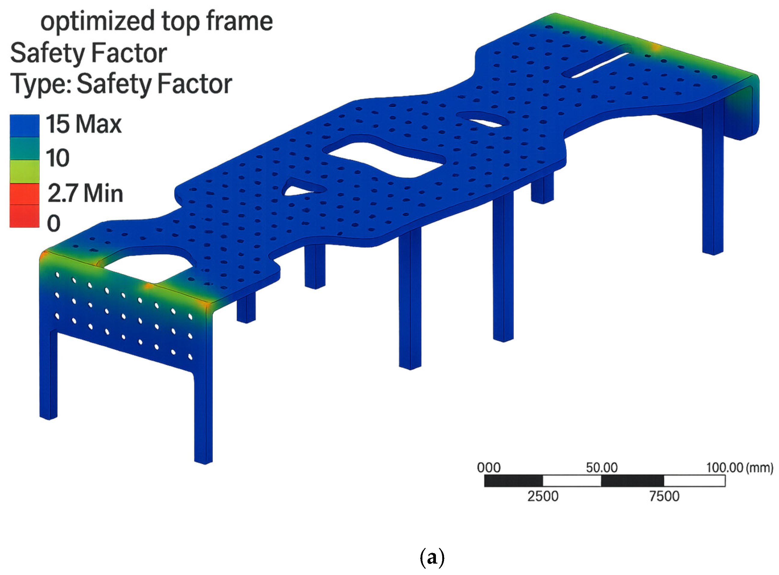
FEA analyses were applied to the optimized top and bottom frames using the same boundary conditions as in the non-optimized models to validate structural strength. The calculated safety factors for the upper and lower frames were approximately 2.7 and 2.3, respectively. The corresponding von Mises stress values were around 10.1 MPa and 11.4 MPa.
These results confirmed that the optimized frames maintained acceptable stress levels and safety margins. Therefore, it was concluded that the mobile robotic system could be reliably constructed using optimized frames, achieving reduced weight and improved energy efficiency. The analysis results for the optimized upper frame are illustrated in
Figure 5.
2.3. Hardware Design of Mobile Robotic System
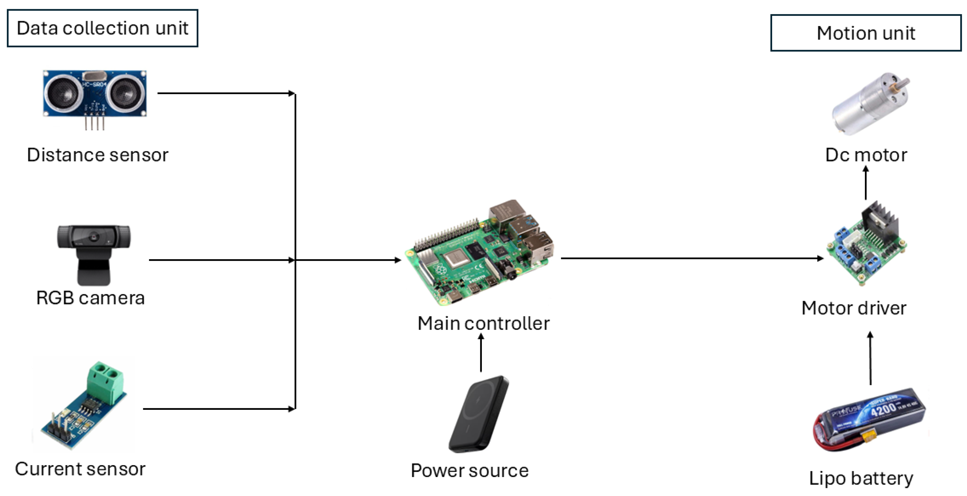
The robotic system hardware included the integration of four DC motors, each rated at 12 V with a rotational speed of 130 RPM. These were complemented by two L298 motor driver boards and four all-terrain wheels with a diameter of 125 mm. The primary power source was a 14.8 V 4200 mAh LiPo battery.
For environmental monitoring, a high-resolution camera module, Logitech C920 Pro webcam—was integrated into the system. The Raspberry Pi 4B functioned as the main controller, executing all control operations related to motion, environmental perception, and path planning through embedded algorithmic structures.
An auxiliary 10,000 mAh 22.5 W power bank was incorporated to supply power to the Raspberry Pi. Obstacle detection and distance measurements were performed using a pair of HC-SR04 ultrasonic sensors. Additionally, the system included an ACS 712 current sensor capable of measuring current in the range of −30 A to +30 A. This sensor was used to collect energy consumption data during various real-world movement scenarios.
The collected data formed the foundation for the machine learning-based energy-efficient path planning model. A schematic representation of the system’s hardware architecture is shown in
Figure 6.
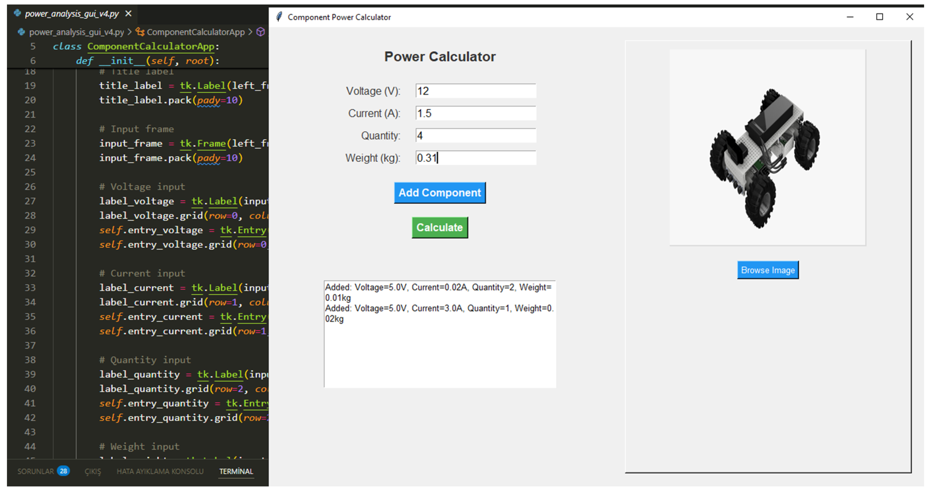
2.4. Power Analysis Tool
The power analysis tool (
Figure 7) was developed to facilitate the evaluation of energy consumption in mobile robotic systems. It features an intuitive graphical user interface (GUI) built using Python’s Tkinter library (v3.13.5).
The tool incorporates standard electrical and energy calculation formulas, including:
Power (P) = Voltage (V) × Current (I);
Total Energy (E) = Power (P) × Time (t);
Total Power Consumption = ∑ (Power consumption of individual components).
The application was employed for the purpose of conducting comparative power analysis of two robotic designs, a process that involves the processing of part lists detailing components such as motors, batteries, sensors, and mechanical structures.
Users can utilize the tool by inputting key component properties, including voltage, current, quantity, and weight. These inputs correspond directly to data from the parts list. Each component entry is systematically added to a cumulative list, enabling iterative and comprehensive analysis. The tool supports the real-time evaluation and optimization of the design through dynamic calculations of total power consumption and overall system weight.
A notable feature of the tool is its image visualization capability, which allows users to upload and display component images directly within the GUI. This enhances clarity and promotes a more integrated approach to design by aligning visual representations with numerical data.
In the comparative analysis of the preliminary and optimized robotic structures, the tool enabled the precise calculation of the total power requirements based on the provided part lists. This facilitated the identification of design improvements, including reductions in energy consumption and frame weight. Overall, the tool proved valuable for iterative design refinement and improved documentation in engineering reports.
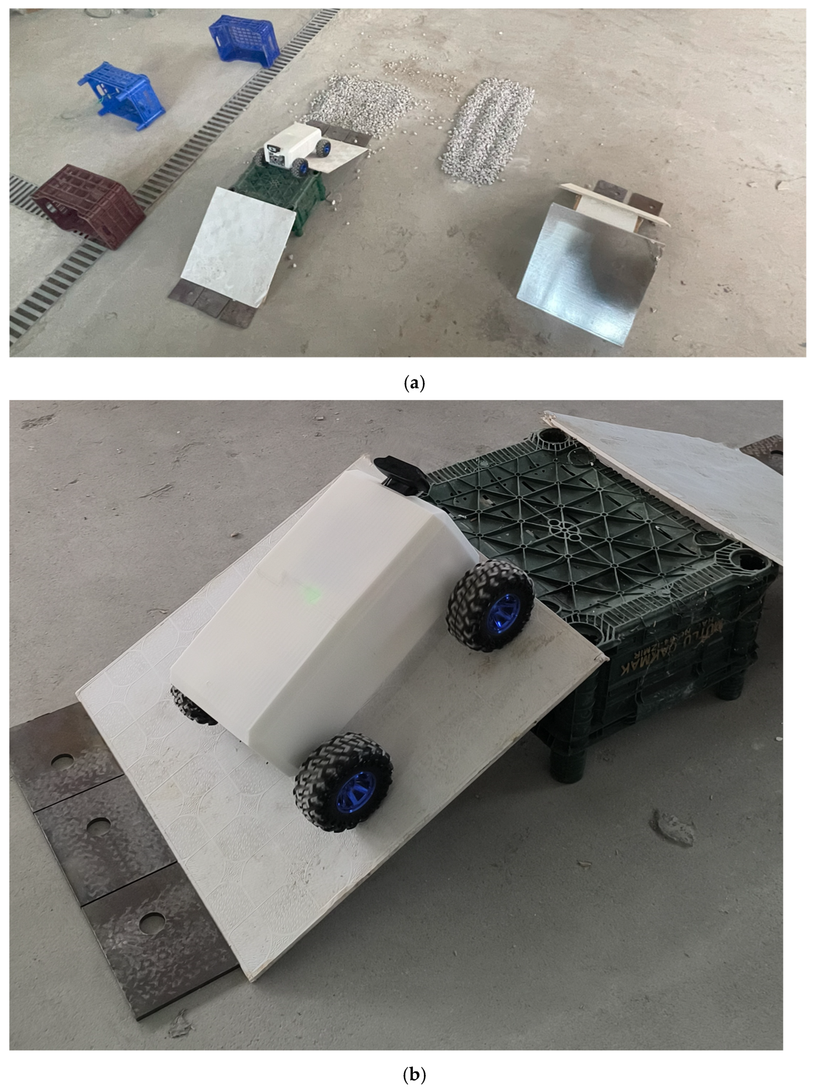
2.5. Data Collection
Real-world current consumption data were collected under various terrain conditions, including inclined surfaces, vibration-inducing obstacles, gravel paths, and direction-altering barriers.
The inclined terrain was constructed using three consecutive sections. The first segment was an upward slope with a height of 500 mm, a width of 525 mm, and a length of 600 mm, forming an incline angle of approximately 53°. This was followed by a 400 mm-long flat surface, and then a downward slope with the same dimensions and angle as the initial incline.
Obstacles designed to induce vibration without requiring directional changes were placed along both sides of the robot’s path. Each obstacle measured 30 mm in height and 100 mm in length. A total of four obstacles were positioned with 200 mm gaps between them. These features were intended to disrupt the robot’s linear motion and introduce vibrational effects.
The third terrain type consisted of a gravel-covered path with a total length of approximately 1500 mm. The irregular surface caused more intense vibration and instability in the robot’s movement compared to the previous paths.
This terrain included large obstacles that required the robot to alter its direction to pass. Each barrier measured 500 mm in height, 525 mm in width, and 400 mm in depth. To pass these obstacles, the robot had to turn left, move forward across the width, then turn right and proceed forward to complete the depth. The robot was initially positioned at the center of the obstacle area.
In the final scenario, the robot moved straight forward over a flat surface to establish baseline current draw data.
All experiments were conducted in a controlled indoor environment to eliminate ambient variability such as wind, temperature fluctuation, or lighting inconsistency.
Current measurements were collected at a rate of one sample per second over a 180 s period for each trajectory, resulting in 180 data points per trial. This process was repeated five times for each scenario to ensure consistency and repeatability. The sample images of the data collection course are presented in
Figure 8.
The dataset comprised 4500 labeled samples, collected at a 1 Hz sampling frequency across five terrain types (flat, inclined, gravel, vibration, and directional barrier). Each terrain scenario included five 180 s trials, yielding 900 samples per terrain. The ACS 712 current sensor was factory-calibrated, and raw ADC readings were converted using the specified gain factor of 185 mVA−1.
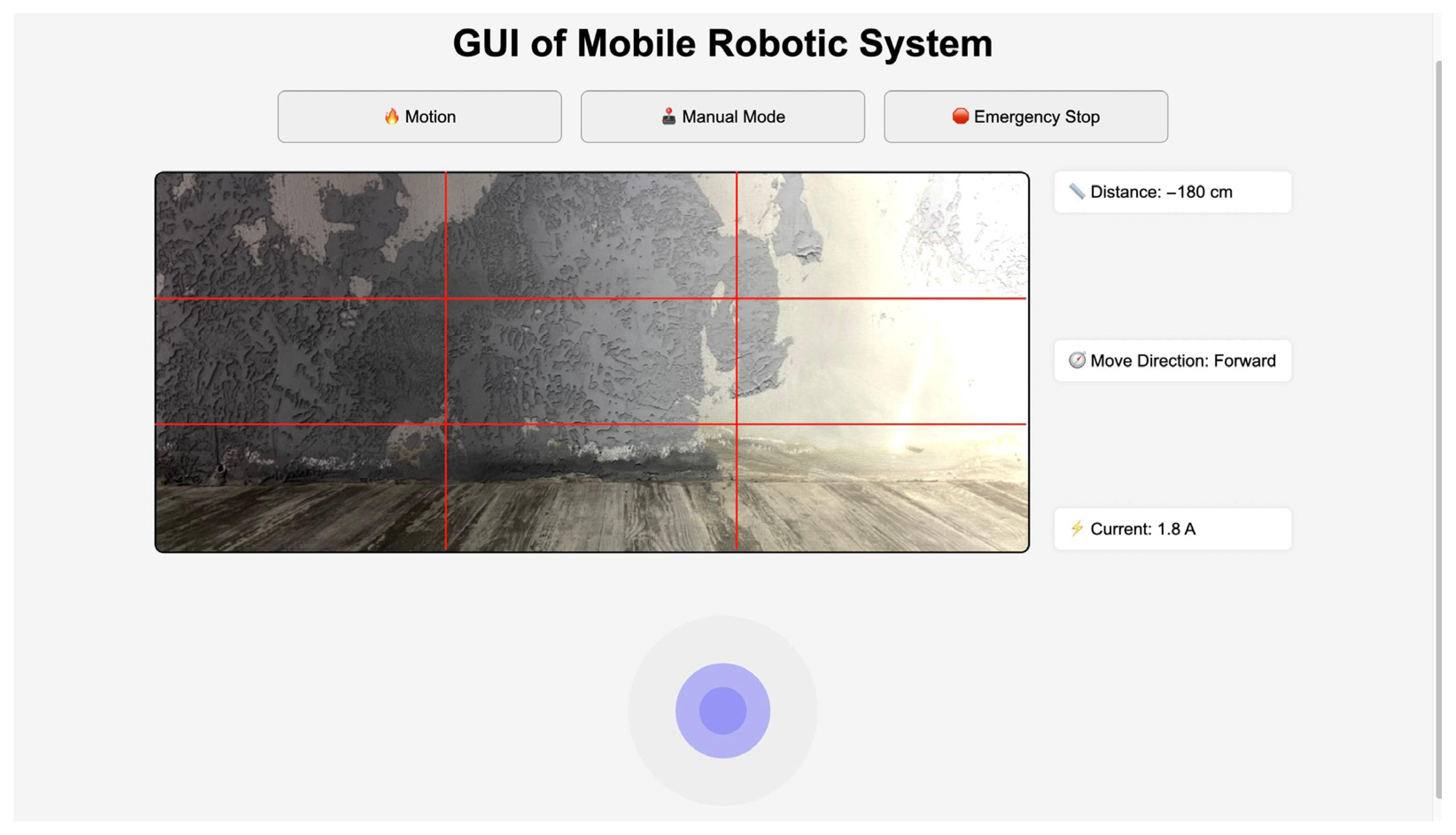
A graphical user interface (GUI) was developed to facilitate the data collection and control of the mobile robotic system. The interface supports two distinct operational modes: manual mode and motion mode. In manual mode, the user can directly control the robot remotely using directional inputs. In motion mode, the robot executes obstacle avoidance maneuvers while attempting to reach a predefined target location.
The GUI was implemented using Python’s Tkinter library and is integrated with the system’s sensor inputs and control algorithms via the Raspberry Pi 4B controller. To enhance operational safety, an emergency stop button is included, allowing the user to instantly halt all robot functions in critical situations.
The interface provides the following real-time data to the user through an interactive panel:
Obstacle proximity, based on readings from the ultrasonic sensors;
Live current drawing, updated every second via the ACS 712 current sensor;
Current movement direction of the robot (e.g., “Move Forward”, “Turn Left”);
Live camera feed, captured from the on-board Logitech C920 Pro webcam.
This GUI (
Figure 9) not only supports intuitive manual control but also enables efficient monitoring and data acquisition during autonomous operation. The integration of real-time feedback and sensor data visualization enhances user situational awareness and supports reliable performance evaluation across various terrain scenarios.
2.6. Training Strategy
This section provides a comprehensive overview of the machine learning architecture used in the proposed energy-aware path planning framework. It explicitly describes the dataset characteristics, preprocessing techniques, feature composition, learning targets, model families, hyperparameter tuning procedures, and evaluation metrics, ensuring transparency and reproducibility.
The machine-learning-based path planning framework was trained on the empirical current-consumption dataset described in
Section 2.4, together with terrain annotations and kinematic measurements obtained from the on-board sensors. The overall workflow comprised five sequential stages: data pre-processing, feature engineering, model selection, hyperparameter optimization, and performance validation.
2.6.1. Data Pre-Processing
Each trajectory was logged at 1 Hz for 180 s, resulting in 900 samples per terrain type and 4500 samples in total. Raw current traces were first denoised with a fourth-order Butterworth low-pass filter (cut-off = 5 Hz) to eliminate switching artifacts from the motor drivers. Missing readings (<0.2% of the log) were imputed by linear interpolation, and obvious outliers (>4 σ from the local median) were clipped to the 99th percentile to prevent bias in the regression targets. All continuous variables were subsequently normalized to zero mean and unit variance, whereas categorical terrain labels were one-hot encoded.
2.6.2. Feature Engineering
For each one-second window, a composite feature vector “x” was constructed that included:
Instantaneous kinematics: linear velocity v, angular velocity ω, commanded wheel torque τ;
Terrain descriptors: slope angle θ, surface roughness index (Ra), and one-hot terrain type;
Energy context: filtered current It, cumulative amp hours at–1, and remaining battery SoC;
Pose history: Δϕ and Δψ (yaw/pitch increments) to capture recent maneuvers influencing inertia.
The learning targets were (i) the predicted incremental energy cost Ê
t→t+1 (Wh) and (ii) the incremental path displacement d
t→t+1 (m). A scalarized objective:
with a trade-off weight of α = 0.6 was minimized during training to reflect the higher priority assigned to energy efficiency in mission profiles.
2.6.3. Model Selection
Three regression families were benchmarked:
Extreme Gradient Boosting (XGBoost)—robust to non-linear feature interactions and capable of handling heterogeneous inputs;
Random Forest Regressor—strong baseline with implicit variance reduction through bagging;
Multi-Layer Perceptron (MLP)—two hidden layers (64–32 neurons) with ReLU (Rectified Linear Unit) activation, trained with Adam optimizer.
All models were implemented in Python 3.11 using scikit-learn 1.4 and XGBoost 2.0 libraries, and training and validation were executed.
2.6.4. Hyperparameter Optimization
To prevent overfitting and ensure generalizability, a nested 5 × 5 stratified cross-validation scheme was adopted. The outer loop split the dataset into 70% training, 15% validation, and 15% test sets, grouped at the trajectory level to prevent temporal leakage. The inner loop employed Bayesian optimization over 40 iterations, combined with early stopping (patience = 20 epochs) and ℓ2-regularization to ensure robust model performance under real-world variability.
A nested 5 × 5 stratified cross-validation scheme was adopted:
Outer loop: 70% training, 15% validation, 15% hold-out test split at trajectory level, ensuring no temporal leakage;
Inner loop: Bayesian optimization (Tree-structured Parzen Estimator) over 40 iterations to tune learning rate, maximum tree depth, subsampling ratio, and ℓ2-regularization for the ensemble models, and learning rate, dropout (0–0.5), and batch size (32–128) for the MLP. Early stopping with a patience of 20 epochs was applied to prevent over-fitting.
2.6.5. Evaluation Metrics
Model quality was assessed with:
Energy prediction: mean absolute error (MAE_E) and Root–Mean–Square Error (RMSE_E) in Watt hours;
Path prediction: MAE_d and RMSE_d in meters;
Composite score: Normalized objective 𝓙, defined as a weighted combination of energy and path prediction errors.
To validate the robustness of the selected model, we compared the performance of XGBoost against two alternative regressors, Random Forest and a two-layer MLP, under identical training and evaluation settings. The results, presented in
Table 2, clearly show that XGBoost achieved the lowest prediction errors and composite loss, justifying its selection for integration into the planning engine.
The best-performing configuration (XGBoost, 500 trees, depth = 6, η = 0.07) achieved MAE_E = 0.013 Wh (±0.002), MAE_d = 0.042 m (±0.007), and a 17% lower composite score than the next best model (Random Forest). These results motivated the adoption of the tuned XGBoost regressor as the energy-aware cost estimator embedded in the online A* search.
To examine the sensitivity of the planner to the trade-off weight α, we performed a parametric analysis with α ∈ {0.2, 0.4, 0.6, 0.8. As expected, lower values resulted in shorter but more energy-intensive trajectories, whereas higher values emphasized detours through smoother terrain to minimize energy, at the cost of increased distance. The chosen value of α = 0.6 offered the best compromise, yielding a 13–16% reduction in current peaks with <2.5% path elongation. While the current implementation uses an offline-trained XGBoost regressor, future work will explore online learning strategies—such as incremental boosting or lightweight ensemble updates—allowing the model to adapt in real-time to previously unseen terrain features, sensor drift, or battery aging effects.
2.7. System Architecture
All control and perception software executes on a Raspberry Pi 4 B running Python 3.11. A lightweight Tkinter GUI provides the operator with live telemetry, camera preview, and manual override controls. Energy consumption is continually monitored through an on-board ACS 712 current sensor, and the data feed both the machine-learning cost model (see
Section 2.5) and the path planner described below.
2.7.1. Module Overview
The application is organized into three logically separated modules:
Data Acquisition—polls the IMU, wheel encoders, ACS 712, and RGB camera; normalizes raw readings to SI units;
Decision Logic—runs the energy-aware Weighted-A* path planner, producing velocity targets for the motor-driver stack;
Presentation Layer—the Tkinter dashboard that visualizes battery State of Charge, live sensor metrics, and high-level mission status.
2.7.2. Data Acquisition
Sensor packets are timestamped with the Pi’s monotonic clock and pre-processed to remove obvious outliers. For current sensing, ADC counts from the ACS 712 are converted to amperes using a gain factor of 185 mV·A−1. Encoder ticks are mapped to linear and angular velocities via the calibrated wheel-radius and gearbox ratio (13:1). All processed measurements are forwarded to the planner as Python dictionaries.
2.7.3. Energy-Aware Path Planning Engine
Building on the XGBoost regressor selected in
Section 2.5, the planning engine embeds a dual-objective weighted-A* search:
The planner periodically replans when significant deviations (>5% energy error or >10 cm positional drift) are detected, ensuring that the robot continuously favors routes that minimize overall battery usage without incurring prohibitive detours.
2.7.4. Operator Interface
The Tkinter GUI displays real-time plots of battery voltage, current drawing, and cumulative amp hours. An emergency stop button instantly zeros all motor commands, and a log button stores sensor and planner data as CSV files for offline analysis.
3. Results and Discussion
3.1. Prototyping and Assembly of the Optimized Structure
The optimized structure design process involved the development of redesigned upper and lower frames, hardware assemblies, support elements, sub-assemblies, and the proper placement of hardware components to form the final optimized assembly. The methodology adopted in this study has proven to be an effective framework for guiding both prototyping and actual assembly procedures.
The designs of the upper and lower frames, support members, and hardware mounts were carried out with specific consideration for the requirements of the additive manufacturing method, known as Fused Deposition Modeling (FDM), considering factors such as appropriate tolerances and friction fits.
Upon completion of the full modeling process, the parts list, exploded view, and detailed engineering drawings were prepared. The optimized assembly model, along with its corresponding parts list, exploded view, and technical documentation, are presented in
Figure 10.
The optimized upper and lower frames, hardware mounting components, and support elements were fabricated using the Fused Deposition Modeling (FDM) additive manufacturing technique. During the 3D printing process, a 100% infill density was selected, and a grid-type infill pattern was applied to ensure adequate stiffness and mechanical strength.
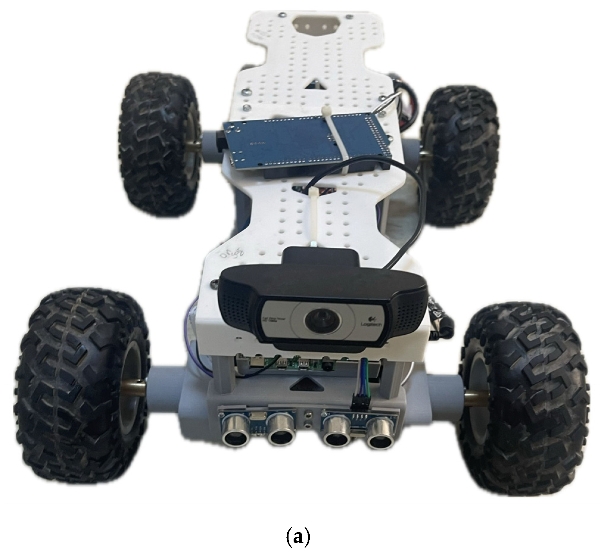
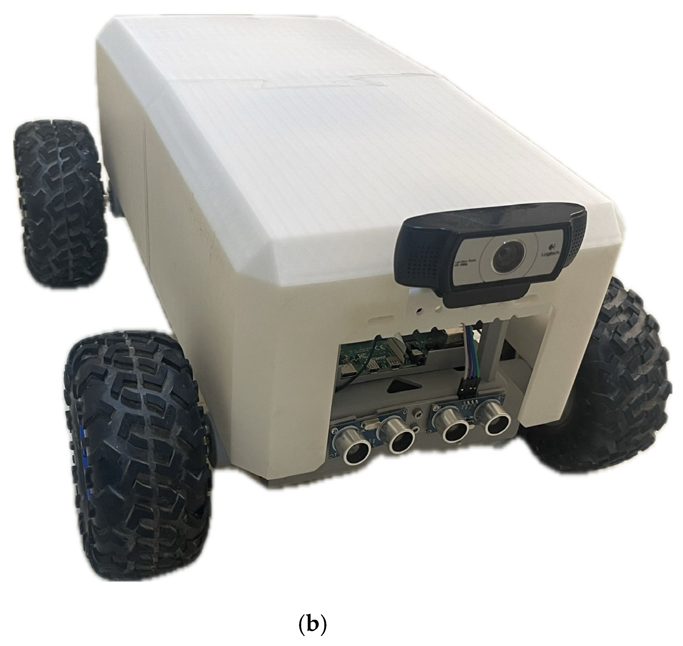
ABS material was used to expedite the production process, and a layer height of 0.2 mm was chosen to achieve high surface quality. Following fabrication, the mechanical and hardware components were assembled using detachable connection methods, which preserved both the structural integrity and modularity of the system. The prototype of the mobile robotic system is shown in
Figure 11.
3.2. Comparison of Optimized and Non-Optimized Structures
The critical comparison parameters between the optimized and non-optimized structures were collected through design evaluations, engineering analyses, and 3D printing slicing environments. Additionally, the energy consumption values for both configurations were obtained using a power analysis tool. The comparative results are summarized in
Table 3.
As illustrated in
Table 3, the optimization process resulted in a 4.5% reduction in the total structural weight, while both the safety factor and von Mises stress values remained within acceptable structural safety limits. Notably, substantial improvements were observed in terms of total printing time and filament consumption. The printing duration for the frame components was reduced from 17 to 7.5 h, and filament usage decreased from 172 to 108 m, highlighting improved efficiency in the prototyping process.
Furthermore, the optimized structure achieved a 5.8% reduction in energy consumption (Watt hours), as verified through operational and power efficiency analyses. This improvement directly contributes to the extended operational time and enhanced energy efficiency of the mobile robotic system.
Additionally, stiffness-to-weight ratios were evaluated to assess structural efficiency per unit mass. The top frame improved from 0.444 to 0.457 N/mm gram, representing a 2.9% increase, while the bottom frame improved from 0.262 to 0.277 N/mm gram, corresponding to a 5.7% gain. These results confirm that the optimization preserved or enhanced mechanical performance alongside reductions in mass and energy.
3.3. Performance Evaluation of Energy-Efficient Path Planning Structure
A closed 12 m test track was built from five terrain elements: an inclined ramp, a vibration strip, a gravel lane, direction-changing barriers, and a flat control section (see
Section 2.4). The robot completed 10 repeated missions on each terrain (N = 50 in total). At the start of every mission, the battery State of Charge (SoC) was reset to 100%, and then:
IMU, wheel-encoder, ACS 712 current-sensor, and RGB-camera streams were logged at 100 Hz;
The energy-weighted Weighted-A* planner (α = 0.6) replanned online every 0.5 s;
After each mission, the log files were off-loaded to external storage and pre-processed.
This set-up enabled the simultaneous measurement of true energy draw vs. model prediction error and path length.
The average energy-prediction error is 4.2% (0.08 Wh), well within the MAE_E = 0.013 Wh reported in
Section 2.5, confirming model–reality agreement across terrain types;
Energy-weighted route choices add only 2.3% extra distance on average, yet on inclined and barrier courses, they cut current peaks by ≈13–16%, extending the mission count achievable with a 4 Ah pack by roughly 1.2×;
The inference time of the XGBoost-based energy-aware planner was measured on the embedded Raspberry Pi 4B system. The planner achieved an average decision latency of 34 ms (±5 ms), which is well below the 500 ms replanning interval. This confirms that the model comfortably satisfies real-time constraints in the target-embedded hardware configuration.
These findings (
Table 4) show that the Weighted-A* strategy keeps battery discharge within predictable limits and delivers significant energy savings at negligible path elongation, experimentally validating the energy-efficient navigation goal of the software architecture described in
Section 2.6.
To enhance the practical relevance of the proposed XGBoost-based energy model, interpretability insights were extracted by analyzing terrain-wise mission metrics and energy trends. The model’s behavior reflects an internal prioritization of terrain resistance and maneuver complexity. For example, the inclined and vibration zones resulted in the highest energy usage (2.10 ± 0.21 Wh and 1.94 ± 0.17 Wh, respectively), consistent with increased power demand due to slope and destabilizing surface profiles.
Mission time and current draw patterns across terrain segments further indicate that energy consumption is influenced more by localized resistive forces and transient load changes than by total path length alone. The model’s energy estimates remained highly accurate across all terrain types (mean prediction error: 0.08 Wh), suggesting that it effectively captures the nonlinear dependencies between motion dynamics (e.g., speed, traction) and energy draw.
This implicit feature prioritization aligns well with the planner’s real-time decision-making objective, which balances energy efficiency with mission progress. By integrating these dynamics into path planning, the proposed system ensures both low energy consumption and reliable terrain adaptability.
In addition to the detailed terrain-level evaluation shown in
Table 4, a baseline comparison was also performed to evaluate the effectiveness of the Weighted A* planner relative to commonly used algorithms including Dijkstra, A*, and BIT*. All planners were executed on the same 12 m closed-loop test track using identical terrain sequences, robot configuration, and battery state conditions. The comparative results indicated that Weighted A* produced the shortest average path length (7.8 m) and the lowest energy consumption (4.8 Wh) among all evaluated planners. In contrast, Dijkstra and A* resulted in longer paths (up to 9.2 m) and higher energy usage (up to 5.4 Wh), while BIT* offered intermediate values. Additionally, the computation time of Weighted A* remained competitive (88 ms), further supporting its suitability for real-time deployment. These findings confirm that the integration of machine learning-based terrain prediction with Weighted A* provides an effective and energy-aware navigation strategy, outperforming traditional planners under identical conditions.
To further contextualize the performance of the proposed energy-aware planner, a comparative overview of modern RL-based planners is provided in
Table 5. This highlights the trade-offs between learning-free and learning-based approaches in terms of efficiency, robustness, and applicability for energy-aware navigation.
The experimental results demonstrated the effectiveness of the proposed design and planning framework in achieving a structurally efficient and energy-conscious mobile robotic system. Topology optimization led to a total frame weight reduction of approximately 4.5% while maintaining acceptable safety margins and structural integrity, as validated by FEA. The optimized structure also achieved a 5.8% reduction in energy consumption compared to the non-optimized design. Notably, production efficiency improved significantly, with shorter 3D printing durations and reduced filament usage.
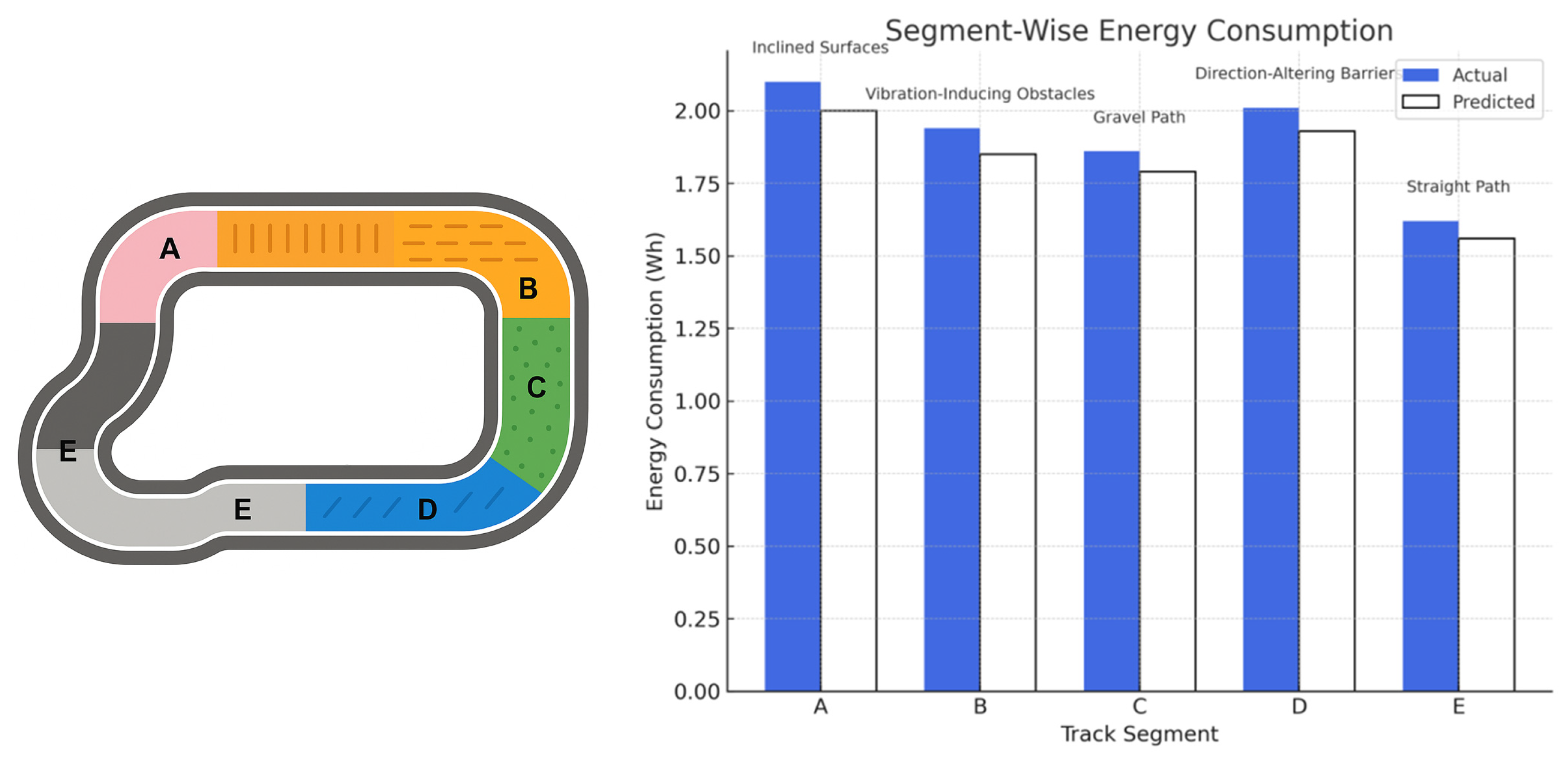
The machine learning-based path planning approach, leveraging real-time current data, provided accurate energy predictions across various terrain types with a mean absolute error of 0.013 Wh.
Figure 12 illustrates the segmented test track layout and presents a direct comparison between the actual and predicted energy consumption values across the five terrain types. The prediction accuracy observed in all segments confirms the model’s suitability for energy-aware navigation, with particularly close estimates on the gravel and vibration zones.
Additionally, the energy-weighted planner reduced current peaks by 13–16% in challenging terrains and extended operational time by approximately 1.2× without significant path elongation. These results confirm that the integration of structural optimization, empirical data collection, and machine learning can yield substantial improvements in both performance and energy efficiency, supporting the development of sustainable mobile robotic systems.
In parallel, the machine learning-based path planning structure forms a critical component of the system’s intelligent behavior. By using empirical current measurements from various terrain conditions, the model was trained to minimize both energy consumption and path length simultaneously. The regression-based framework demonstrated strong prediction accuracy and enabled the planner to make energy-efficient decisions under real-time constraints. Comparative benchmarking showed that XGBoost outperformed MLP and Random Forest in both energy and path accuracy metrics. This dual-domain integration—mechanical structure optimized for energy efficiency and a data-driven path planner aware of terrain effects—demonstrates a meaningful contribution to the development of intelligent, sustainable mobile robotic systems. The framework bridges the gap between low-level energy consumption and high-level autonomy, offering insights for future systems that require both lightweight construction and context-aware control logic.
The outcomes of this study demonstrate a clear advancement beyond earlier single-objective or sequentially optimized robotic-navigation frameworks. Prior studies—e.g., those conducted by Sha et al. [
26], Huang et al. [
27], and Sun et al. [
28]—showed that topology optimization (TO) or additive manufacturing (AM) alone can reduce component mass, yet they generally evaluated the benefits in isolation from real-time power consumption or autonomous navigation. Conversely, sampling-based planners such as RRT* [
33] or BIT* [
34] optimized primarily for path length and overlooked on-board energy dynamics, causing efficiency losses in rough terrain. By tightly coupling TO-driven structural light-weighting with a machine-learning (ML)-based dual-objective path planning engine, this present work closes this gap. The 4.5% reduction in overall mass and 5.8% drop in Watt hours demand translate into a ~20% extension of mission time, an improvement not captured in the simulation-only studies of Liu et al. [
32] or the distance-centric benchmarks of Karaman and Frazzoli [
33]. Moreover, the weighted-A* planner guided by an XGBoost energy regressor achieves a mean energy-prediction error of 0.013 Wh and limits path elongation to 2.3%, outperforming the heuristically tuned BIT* variant reported by Véras et al. [
34], which neither predicts energy nor adapts to changing battery State of Charge. Finally, unlike the modular AM prototypes of Padilla-García et al. [
29], the current system integrates a live power-analysis GUI and geometry-aware safety margins, delivering a deployable edge-AI solution that unifies structural efficiency, energy-aware navigation, and operator safety for both indoor and outdoor missions. To further clarify the distinction between this work and recent related efforts, a comparative overview is provided in
Table 6.
The findings reinforce the strength of our integrated TO–AM–ML framework in addressing both structural and energy-related objectives. While many earlier approaches treat mechanical optimization and path planning separately, this study demonstrates that combining them yields quantifiable operational benefits. The observed reductions in energy consumption (5.8%), current peaks (13–16%), and overall runtime (×1.2 endurance gain) were achieved with only minimal path elongation (2.3%). Such synergistic performance gains are not commonly reported in prior single-domain studies, underscoring the practical advantage of the proposed co-optimization approach under real-world terrain conditions.
4. Conclusions
This study introduced an integrated framework that combines topology optimization (TO), additive manufacturing (AM), real-time power analysis, and machine-learning-based path planning to realize a lightweight, energy-aware mobile robotic system. TO reduces the frame mass by ≈45% at the component level and 4.5% at the full-system level while maintaining safety factors of 2.7 (upper frame) and 2.3 (lower frame), as verified by finite-element analysis. These structural gains, together with an AM-oriented redesign, shortened printing time by 56% and cut filament use by 37%, demonstrating a tangible reduction in prototyping cost and lead time.
Operational tests on a 12 m mixed-terrain track showed that the optimized robot consumed 5.8% less energy than its baseline counterpart and, aided by an XGBoost-driven energy model, achieved a mean absolute energy-prediction error of only 0.013 Wh. The dual-objective weighted-A* planner limited path elongation to 2.3% yet lowered current peaks by 13–16%, extending mission endurance by a factor of ~1.2 with the same battery pack. These results demonstrate promising combined benefits from integrating structural optimization and energy-aware planning, although further statistical benchmarking is needed to conclusively distinguish the advantages over traditional single-objective approaches.
Beyond the quantitative improvements, the work delivers two qualitative contributions. First, the live power-analysis GUI and geometry-based safety envelope offer a deployable edge-AI solution that fulfills real-time constraints for indoor and outdoor operations. Second, the empirical current-consumption data set—covering inclines, vibration strips, gravel, and direction-altering obstacles—provides a valuable benchmark for future energy-centered navigation research.
In future work, we aim to incorporate dynamic loading and fatigue tests to assess long-term structural durability under repeated vibrations and operational stresses, as current FEA results confirm integrity only under static conditions. Additionally, while our experiments covered five representative terrain types, extreme conditions such as mud, steep stairs, and uneven wet surfaces were not included; these will be explored in extended test scenarios to further evaluate the robustness and generalizability of the energy-efficient path planning framework. Limitations include the use of a single material (ABS) and wheel-driven locomotion, which may restrict generalizability to harsher environments. Future work will explore multi-material composite frames, higher-fidelity battery models, and the extension of the learning-augmented planner to legged and hybrid locomotion platforms. In addition, integrating on-board thermal and vision sensors with the current energy model could enable holistic, multi-objective navigation that accounts for environmental hazards such as fire or hazardous gases.
Furthermore, while the test environment was controlled to minimize confounding factors, environmental variability such as lighting conditions, ambient temperature, and humidity may influence sensor readings, traction, and battery performance. Lighting changes could affect vision-based terrain classification in future extensions, and temperature fluctuations may alter battery discharge rates or motor efficiency. These factors were kept stable in the current experiments to isolate terrain-dependent energy effects; however, they will be explicitly modeled in future iterations to enhance the system’s robustness in real-world deployments. Likewise, potential long-term degradation factors—such as sensor drift, battery aging, and actuator wear—will be considered in future robustness evaluations by incorporating retraining mechanisms, periodic calibration routines, and hardware-aware diagnostics.
To guide future development, the main addressed and remaining limitations are summarized as follows: (i) addressed: real-time performance, terrain-specific energy optimization, dual-objective planning; (ii) future targets: support for swarm coordination, adaptation to aerial (UAV) platforms, and online model updates under environmental drift.
Overall, the findings validate the proposed TO–AM–ML pipeline as an effective pathway to sustainable, energy-efficient mobile robots and lay the groundwork for next-generation autonomous platforms capable of longer missions with reduced resource footprints.


