
Calculation Method and Experimental Investigation of Root Bending Stress in Line Contact Spiral Bevel Gear Pairs


Abstract
1. Introduction
2. Meshing Characteristics of Line Contact Spiral Bevel Gear Pairs
2.1. Gear Pair Modeling
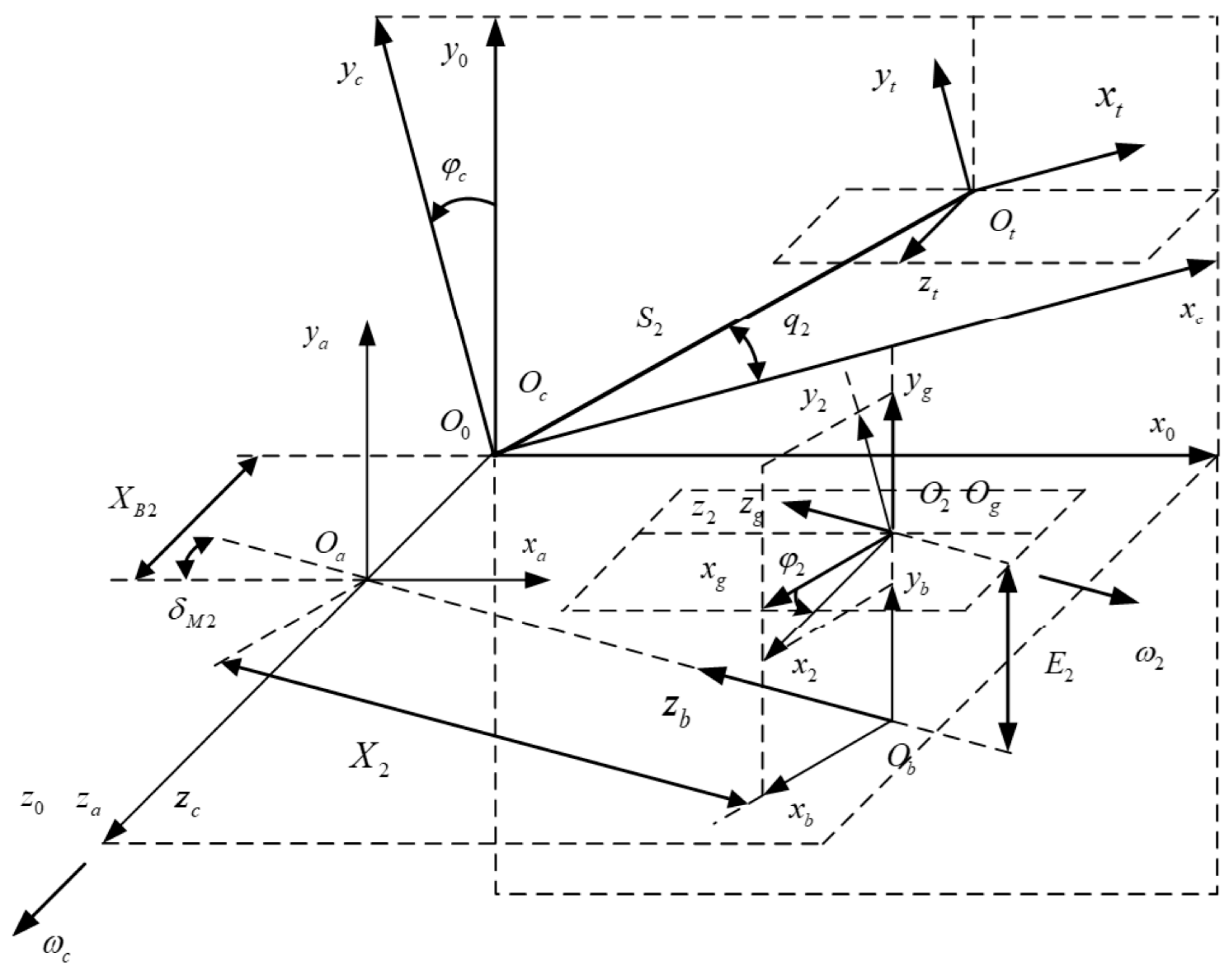
2.1.1. Machining Coordinate Systems for the Gear
2.1.2. Machining Coordinate Systems for the Pinion
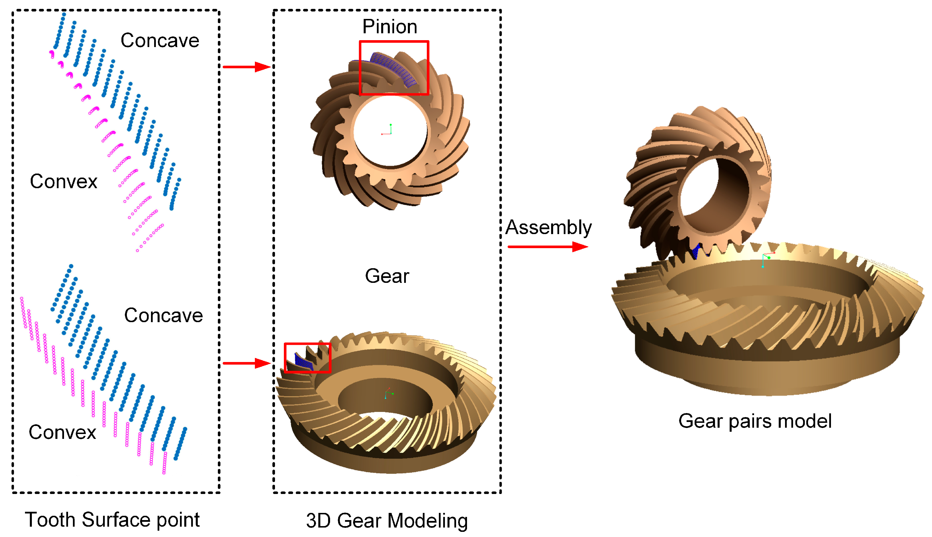
2.1.3. Three-Dimensional Model of the Gear Pairs
2.2. Meshing Simulation Analysis
- (a)
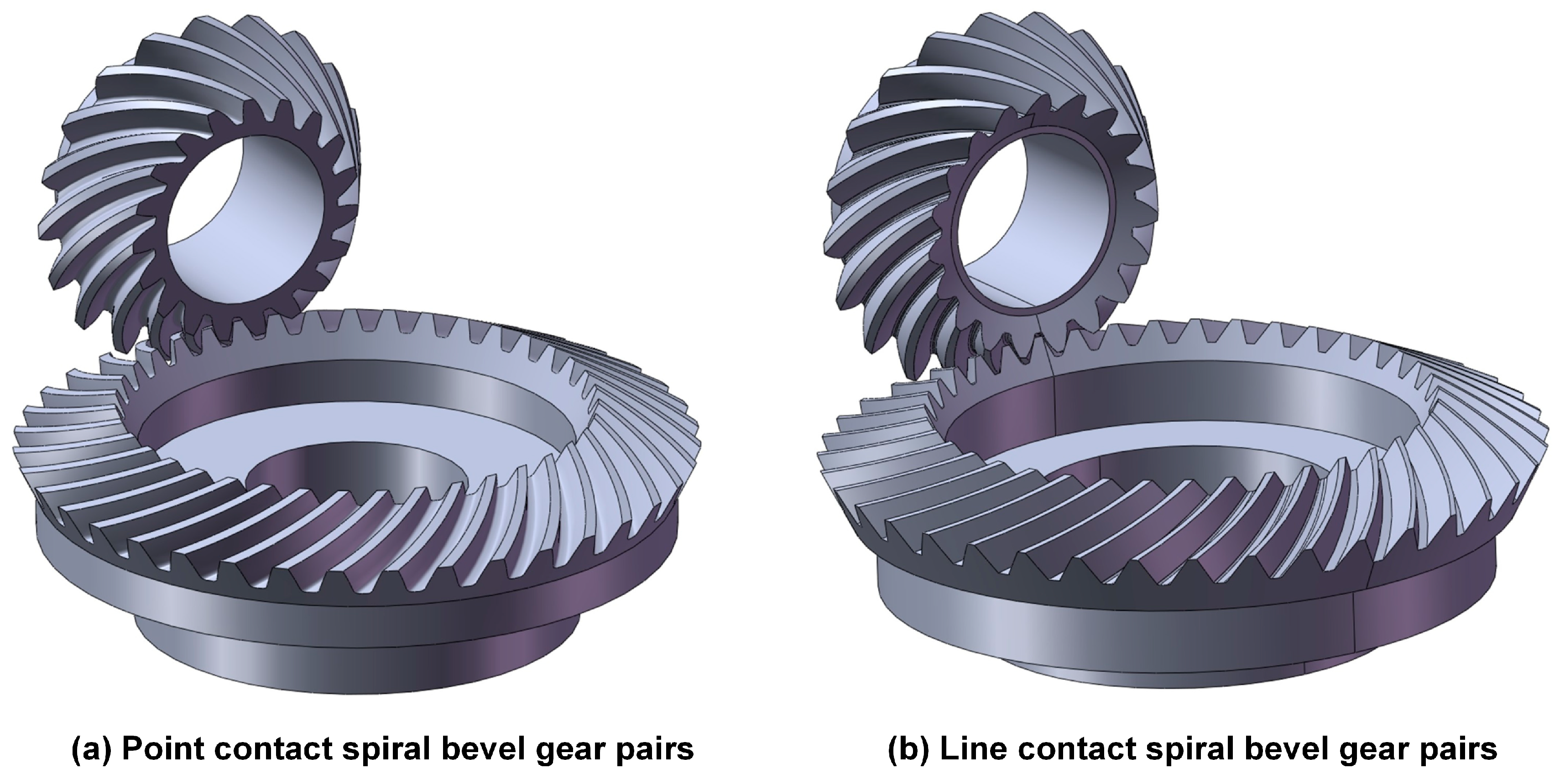
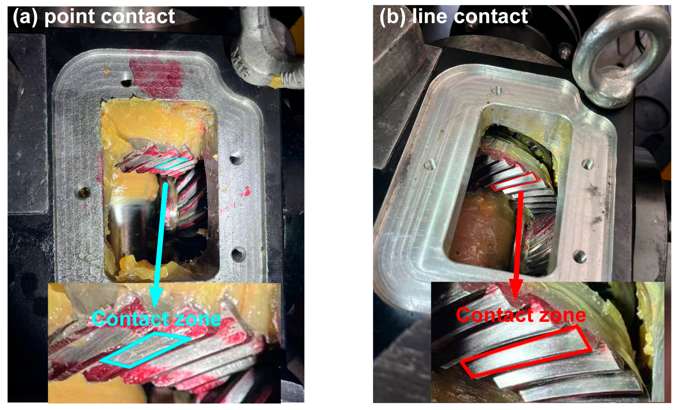
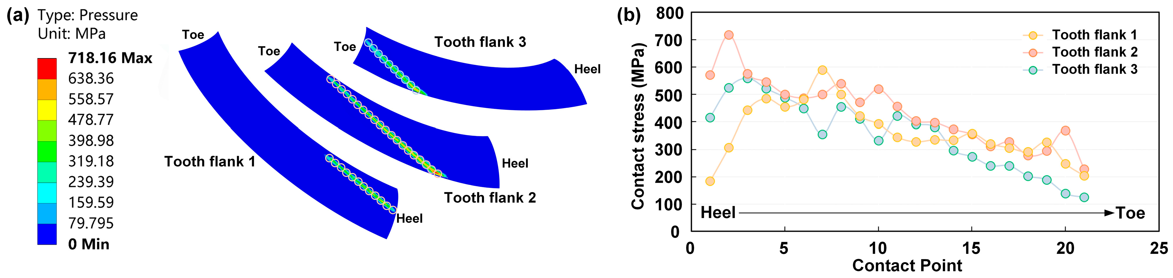
- Unlike the elliptical contact area in point contact gears, the effective contact region in the line contact gear pair covers nearly the entire tooth surface.
- (b)
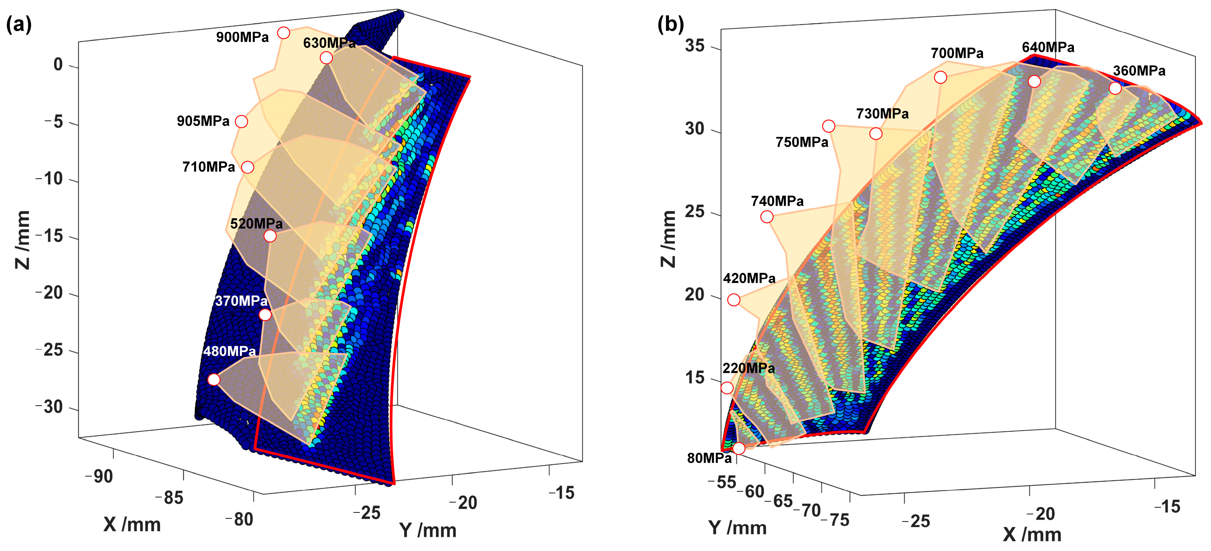
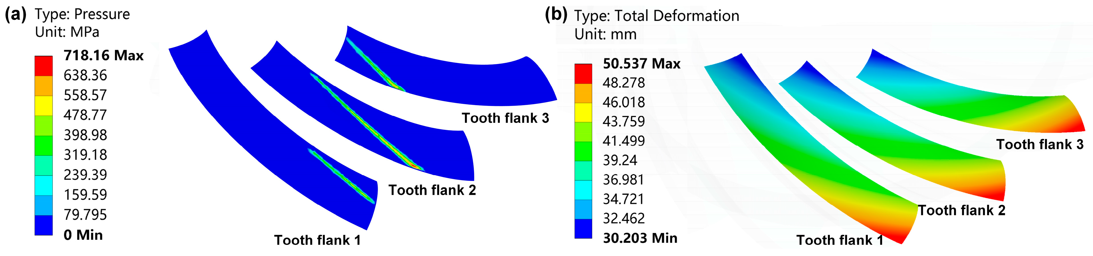
- The maximum stress on the tooth surface is about 750 MPa, a reduction of 16.7%.
- (c)
- The stress distribution shows edge contact along the contact line near the addendum, with the maximum contact stress concentrated in this region. This is attributed to the ideal fully conjugate surface geometry of line contact gears; without profile modification, edge contact tends to occur. However, the overall stress distribution on the tooth surface is relatively uniform, which helps to reduce excessive localized wear and delays the onset of pitting or even tooth breakage.
2.3. Test Validation
3. Line Load Distribution Model on the Tooth Surface
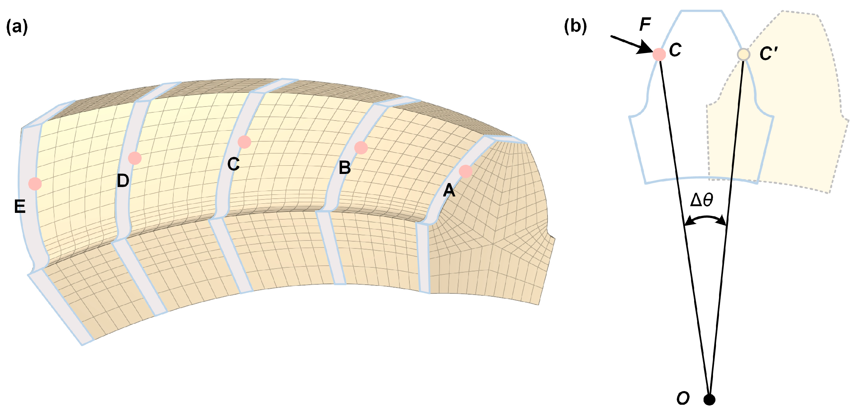
3.1. Analysis of Tooth Surface Conforming Deformation
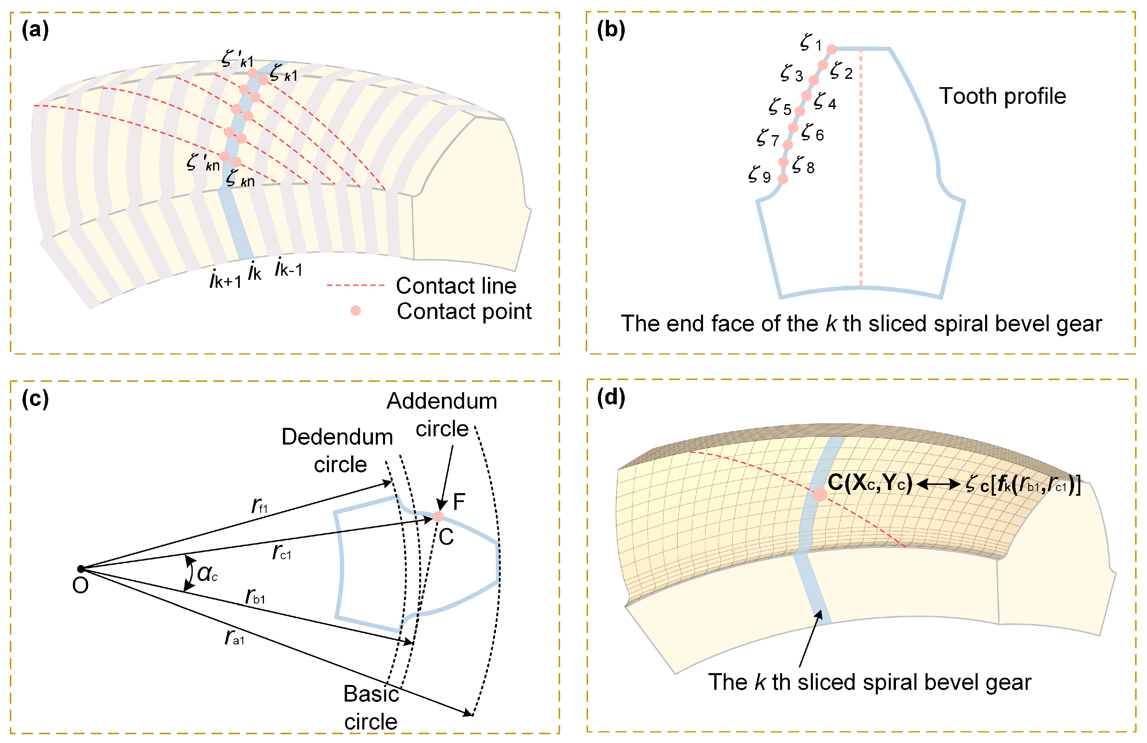
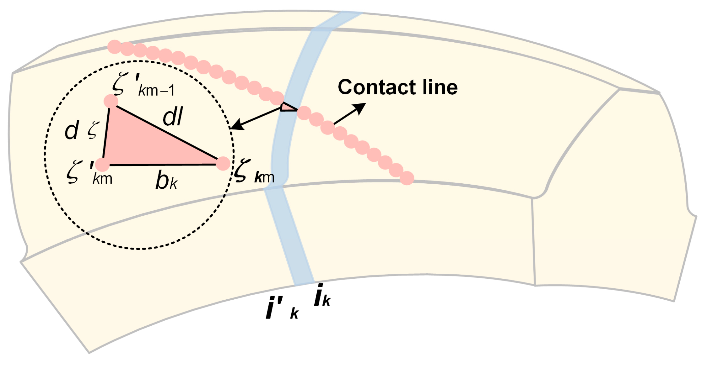
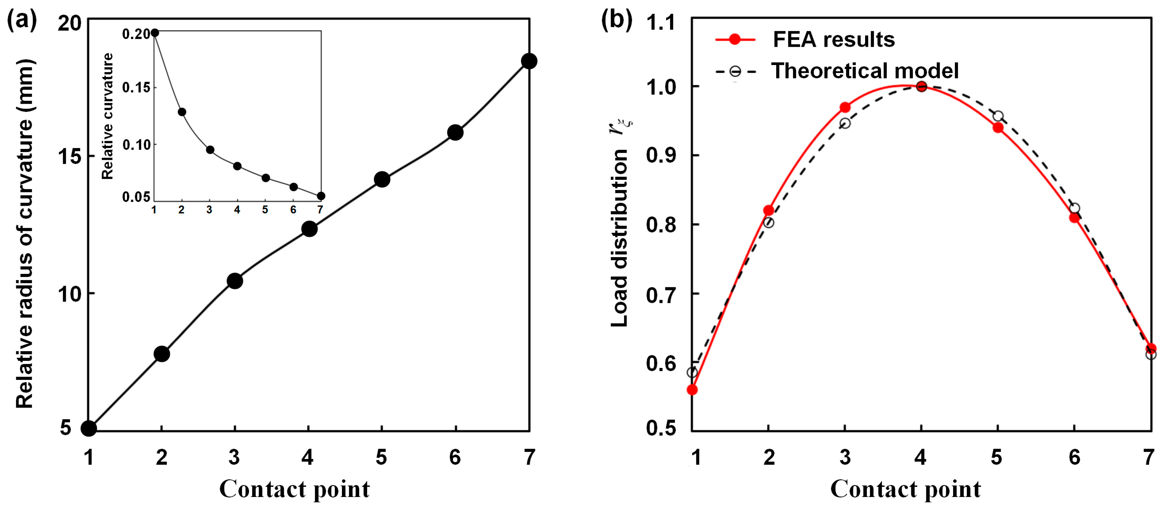
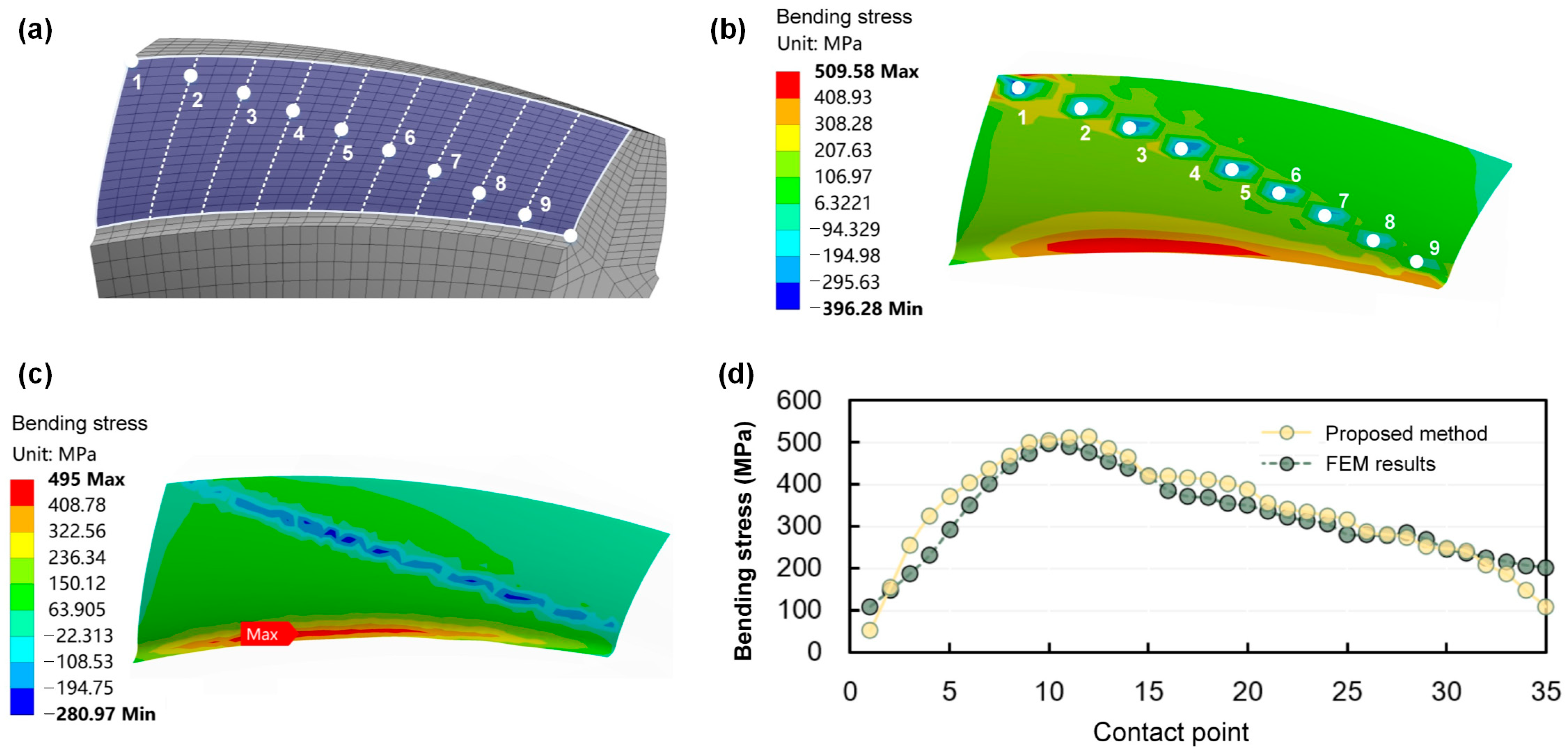
3.2. Calculation of Line Load Distribution on Contact Line
3.3. Verification of Finite Element Simulation
4. Calculation Method for Tooth Root Bending Stress
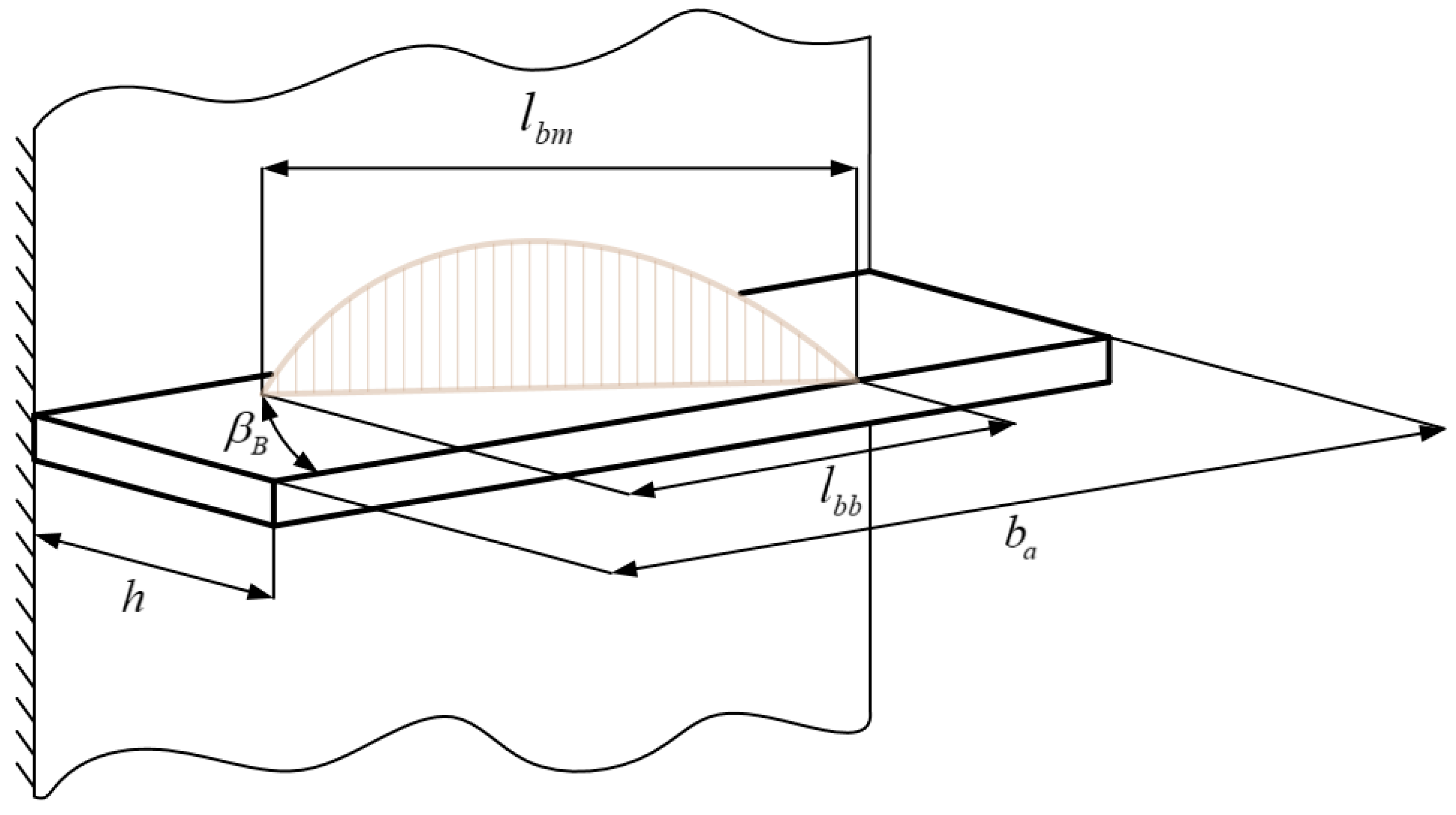
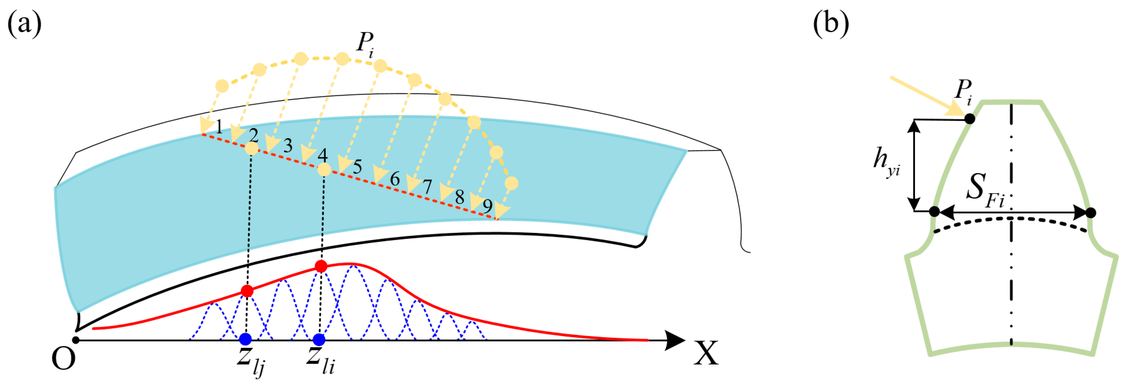
4.1. Bending Moment Distribution of the Tooth Root Critical Section
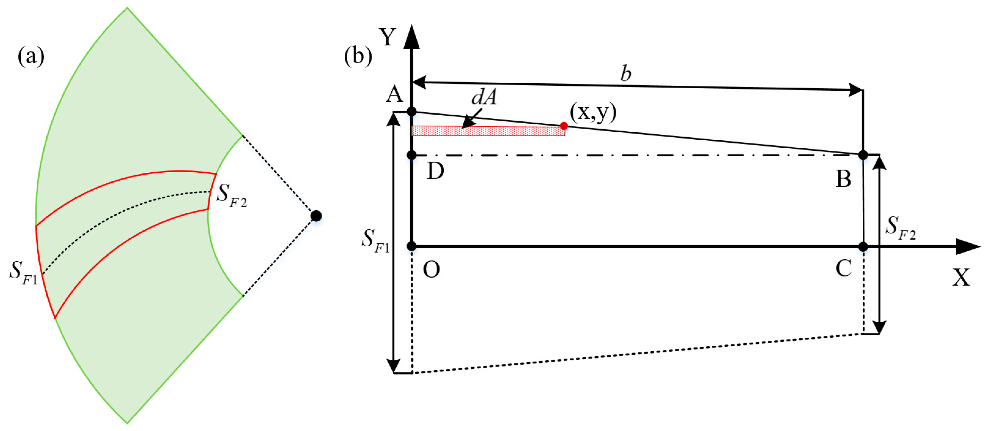
4.2. Calculation of Bending Moment of Inertia at the Critical Root Section
4.3. Derivation and Validation of the Calculation Formula
5. Static Tooth Root Bending Test
5.1. Principle of Root Bending Stress Test
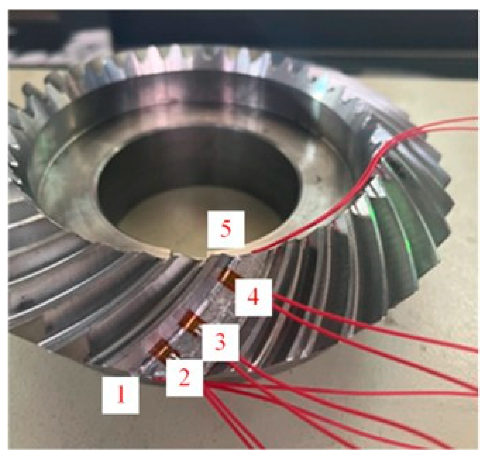
5.2. Test Bench Setup for Root Bending Stress Measurement
- (1)
- The gear with affixed strain gauges was installed in the gearbox, and strain gauge lead wire compression was avoided. Each gauge was checked with a multimeter to detect whether damage had occurred.
- (2)
- After assembling the motor, torque-speed sensor, and gearbox, the strain gauge resistance was remeasured. Then the strain gauge leads were connected to the data acquisition system.
- (3)
- To prevent signal interference caused by wire movement, all strain gauge leads were secured to the surface of the gearbox to minimize undesired vibration or displacement during testing.
- (4)
- The meshing position of the gear pair was adjusted to prevent the addendum from pressing against the strain gauge after fixing and holding the gear pairs in the specified mesh position.
- (5)
- The motor was started and the torque was set to zero, and an input torque of 50 Nm was applied. The zero point of the data acquisition system was calibrated and the sampling frequency was set to 40 Hz.
- (6)
- Strain and stress curves could be output simultaneously. To ensure stable signal acquisition under various loading conditions, the sampling duration was set to no less than 1 min.
- (7)
- The input torque of the motor was increased stepwise to 100 Nm, 150 Nm, and 200 Nm. The above procedures were repeated for each loading condition.
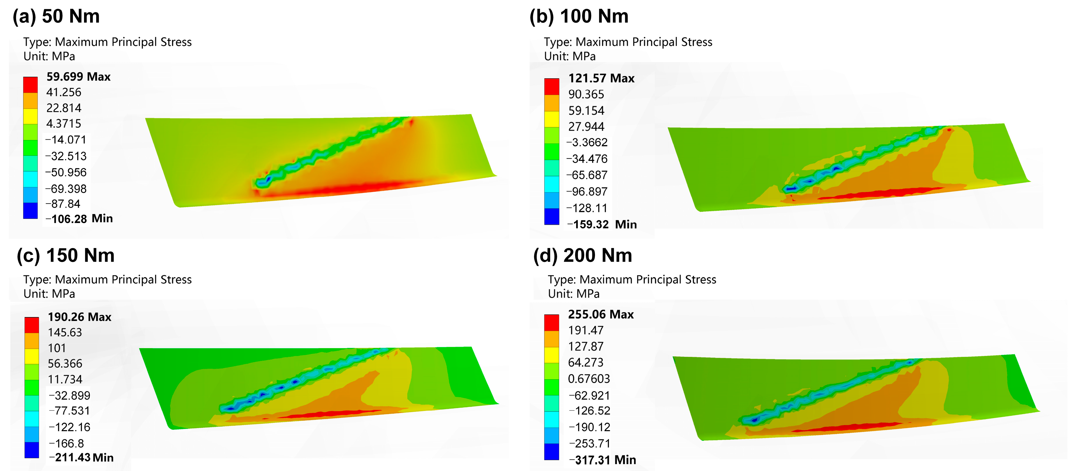
5.3. Results Analysis and Simulation Validation
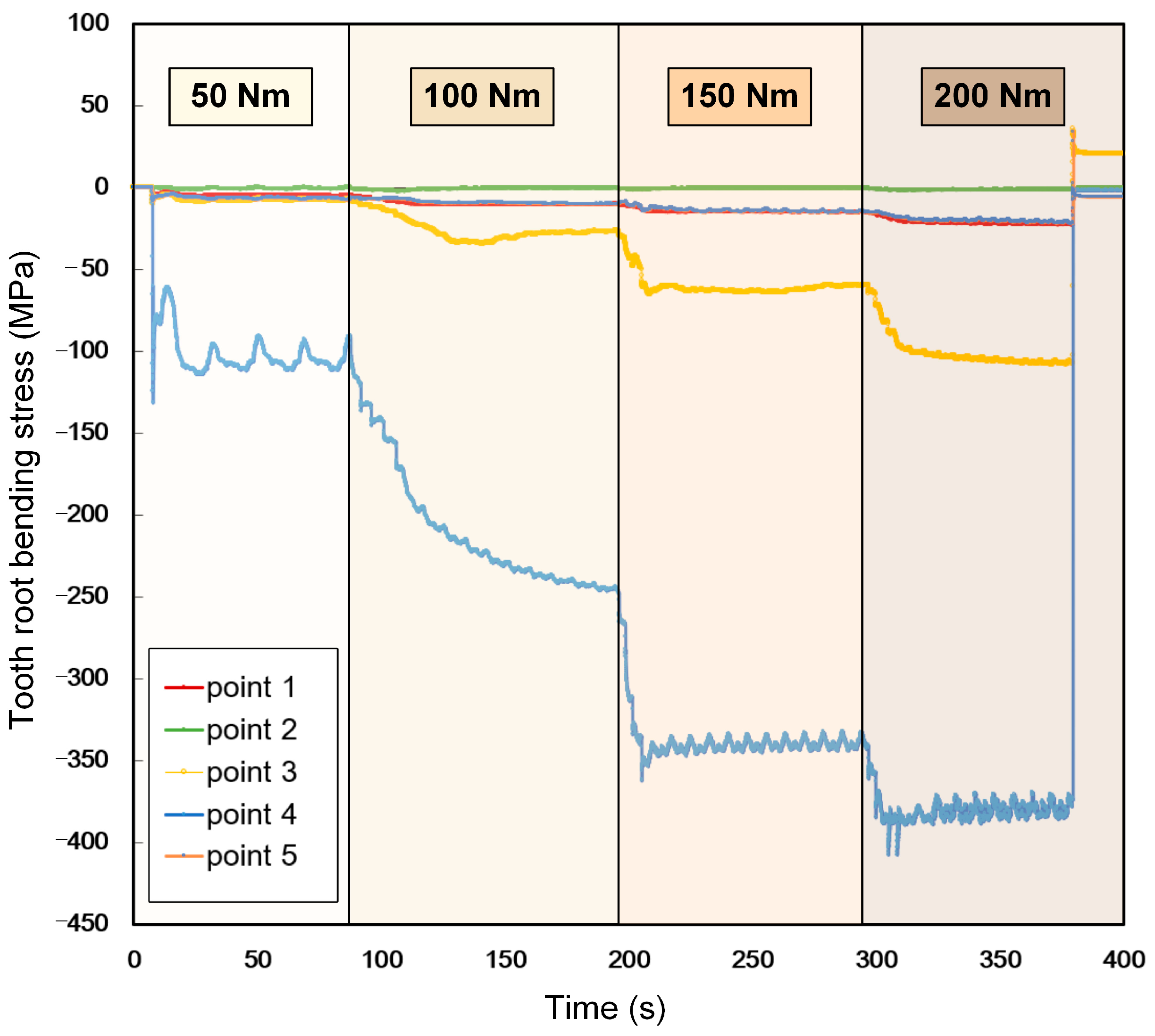
5.3.1. Analysis of Experimental Data
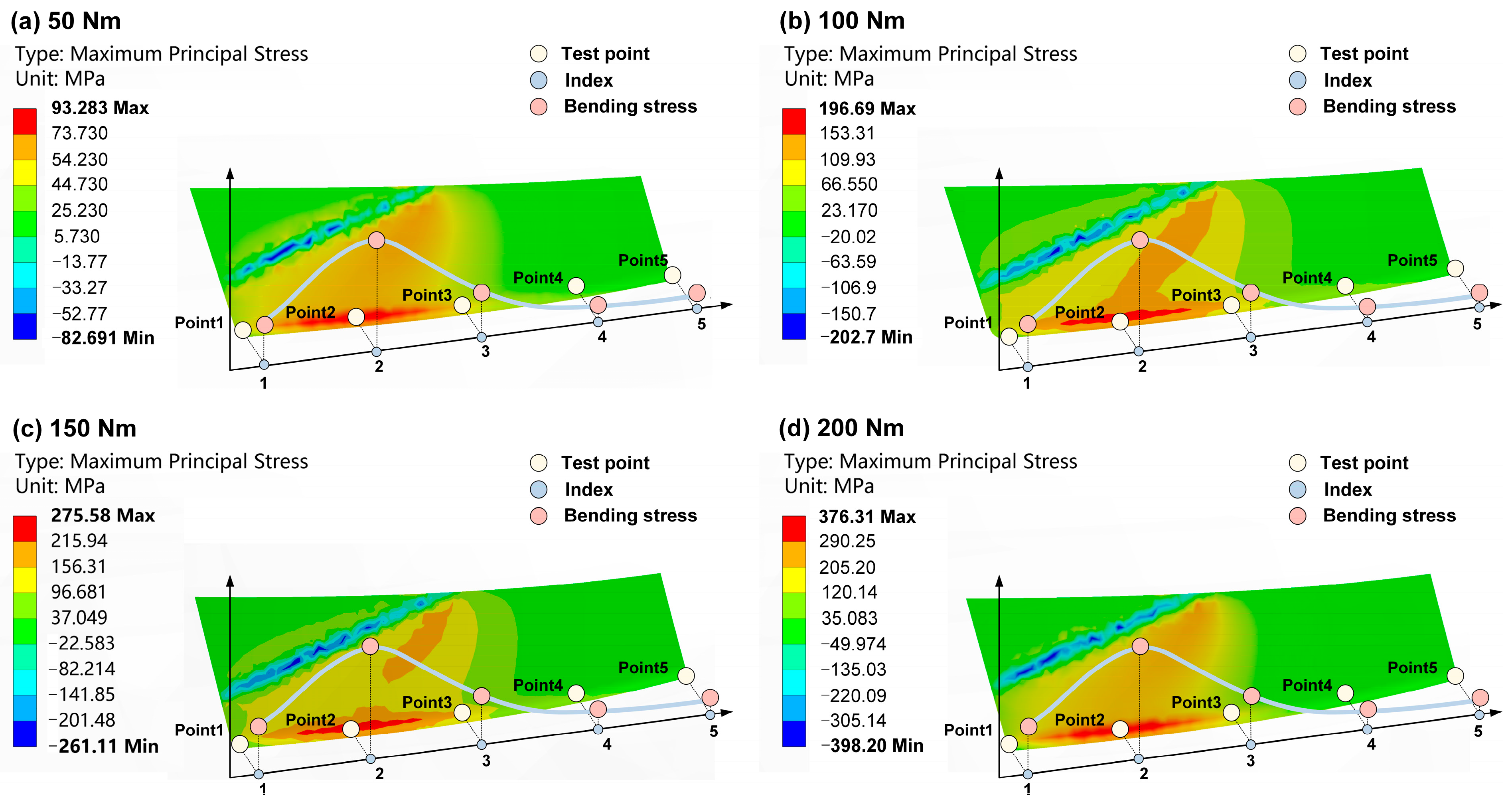
5.3.2. Simulation Validation
6. Conclusions
- (1)
- Unlike the elliptical contact area of point contact gear pairs, the effective contact area of line contact gear pairs spans almost the entire tooth surface. Although edge contact may occur on tooth surfaces, the meshing stress distribution remains relatively uniform. For point contact gear pairs, the maximum tooth root bending stress typically appears near the tooth root at the toe. However, for line contact gear pairs, the maximum stress is located near the heel, which is closely related to the load distribution along the contact line.
- (2)
- The slice method and finite element simulations were employed to investigate the load distribution along the contact line of the gear pairs. Based on these results, the load-sharing ratio of the gear teeth was obtained for the gear pairs with a contact ratio between 2 and 3.
- (3)
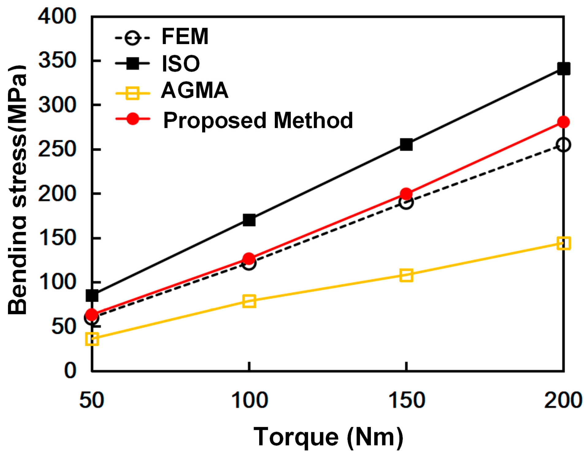
- Based on the load distribution along the contact line, a segmented loading approach is employed to derive the bending moment distribution formula for the critical tooth root section. The geometric characteristics of the critical section are analyzed to obtain its moment of inertia against bending, and a formula for calculating the root bending stress of gear pairs is derived. Compared with the results obtained using the existing standard for root bending stress calculation, which exhibits deviations of up to 40% from FEA, the formula proposed in this study achieves deviations within 10%, demonstrating significantly improved accuracy compared to the ISO standard.
- (4)
- The results of the static tooth root bending stress tests are in good agreement with those obtained from FEA, which almost validates the accuracy of the proposed analytical method for calculating the root bending stress of line contact spiral bevel gear pairs.
Author Contributions
Funding
Data Availability Statement
Acknowledgments
Conflicts of Interest
Appendix A
References
- Litvin, F.L.; Fuentes, A.; Hayasaka, K. Design, Manufacture, Stress Analysis, and Experimental Tests of Low-Noise High Endurance Spiral Bevel Gears. Mech. Mach. Theory 2006, 41, 83–118. [Google Scholar] [CrossRef]
- Fernandes, P.J.L. Tooth Bending Fatigue Failures in Gears. Eng. Fail. Anal. 1996, 3, 219–225. [Google Scholar] [CrossRef]
- Hemanshu, J. Mode and Cause of Failure of a Bevel Gear—A Review. Int. J. Adv. Eng. Res. Dev. 2014, 1, 9. [Google Scholar] [CrossRef]
- Siddiqui, N.A.; Deen, K.M.; Khan, M.Z.; Ahmad, R. Investigating the Failure of Bevel Gears in an Aircraft Engine. Case Stud. Eng. Fail. Anal. 2013, 1, 24–31. [Google Scholar] [CrossRef]
- Gao, Z.; Xing, B.; Bu, J.; Liu, M. Failure Analysis of the Spiral Bevel Gear Made of the 3rd Generation New Low Carbon High Alloy Steel. Aeroengine 2024, 50, 170–174. [Google Scholar] [CrossRef]
- Mu, Y.; He, X. Design and Dynamic Performance Analysis of High-Contact-Ratio Spiral Bevel Gear Based on the Higher-Order Tooth Surface Modification. Mech. Mach. Theory 2021, 161, 104312. [Google Scholar] [CrossRef]
- Mu, Y.-M.; He, X.-M.; Fang, Z.-D. Design and Dynamic Performance Analysis of High-Contact-Ratio Spiral Bevel Gear Based on Ease-off Technology. Int. J. Precis. Eng. Manuf. 2021, 22, 1963–1973. [Google Scholar] [CrossRef]
- Mu, Y.; He, X.; Fang, Z. An Innovative Ease-off Flank Modification Method Based on the Dynamic Performance for High-Speed Spiral Bevel Gear with High-Contact-Ratio. Mech. Mach. Theory 2021, 162, 104345. [Google Scholar] [CrossRef]
- Wang, Y.; Wang, H.; Li, K.; Qiao, B.; Shen, Z.; Chen, X. An Analytical Method to Calculate the Time-Varying Mesh Stiffness of Spiral Bevel Gears with Cracks. Mech. Mach. Theory 2023, 188, 105399. [Google Scholar] [CrossRef]
- Wang, Y.; Yang, K.; Tang, W. Prediction and Test of Stable Transmission Time of Spiral Bevel Gear during a Loss-of-Lubrication Event in Helicopter Transmission System. Ind. Lubr. Tribol. 2022, 74, 111–117. [Google Scholar] [CrossRef]
- Su, J.; Wei, G.; Yang, Y.; Chang, L.; Guo, J. Design and Analysis of Spiral Bevel Gears with Large Contact Ratio. Xi’an Jiaotong Daxue Xuebao 2021, 55, 117–125. [Google Scholar]
- Jiang, Z.; Wang, X.; Chi, H.; Zhao, X. Optimization of Tooth Surface Contact Characteristics of Spiral Bevel Gears by Genetic Algorithm. Mech. Sci. Technol. Aerosp. Eng. 2022, 41, 409–413. [Google Scholar]
- Zhou, C.; Li, Z.; Hu, B.; Zhan, H.; Han, X. Analytical Solution to Bending and Contact Strength of Spiral Bevel Gears in Consideration of Friction. Int. J. Mech. Sci. 2017, 128–129, 475–485. [Google Scholar] [CrossRef]
- Li, L. Research on Machining and Modeling Methods of Line-Contact Spiral Bevel Gears. Master’s Thesis, Tianjin University, Tianjin, China, 2020. [Google Scholar]
- Wang, M. Research on NC Machining Methods of Line-Contact Spiral Bevel Gears. Master’s Thesis, Tianjin University, Tianjin, China, 2022. [Google Scholar]
- Wang, M.; Sun, Y. Cutterhead Approximation Machining Method of Line Contact Spiral Bevel Gear Pairs Based on Controlling Topological Deviations. Int. J. Adv. Manuf. Technol. 2022, 121, 1623–1637. [Google Scholar] [CrossRef]
- Wang, M.; Li, L.; Sun, Y. Tooth Flank Machining and Modelling of Line Contact Spiral Bevel Gears with the Conical Finger-Type Milling Cutter. Int. J. Adv. Manuf. Technol. 2023, 125, 3277–3291. [Google Scholar] [CrossRef]
- ISO 10300-1: 2023; Calculation of Load Capacity of Bevel Gear—Part 1: Introduction and General Influence Factors. International Standards Organization: Geneva, Switzerland, 2023.
- ISO 10300-2: 2023; Calculation of Load Capacity of Bevel Gear—Part 2: Calculation of Surface Durability (Macropitting). International Standards Organization: Geneva, Switzerland, 2023.
- ISO 10300-3: 2023; Calculation of Load Capacity of Bevel Gear—Part 3: Calculation of Tooth Root Strength. International Standards Organization: Geneva, Switzerland, 2023.
- ANSI/AGMA 2003-B97; Rating the Pitting Resistance and Bending Strength of Generated Straight Bevel, Zerol Bevel, and Spiral Bevel Gear Teeth. AGMA: Alexandria, VA, USA, 2010.
- Simon, V. Load Distribution in Spiral Bevel Gears. J. Mech. Des. 2007, 129, 201–209. [Google Scholar] [CrossRef]
- Li, H.; Tang, J.; Chen, S.; Rong, K.; Ding, H.; Lu, R. Loaded Contact Pressure Distribution Prediction for Spiral Bevel Gear. Int. J. Mech. Sci. 2023, 242, 108027. [Google Scholar] [CrossRef]
- Sánchez, M.B.; Pleguezuelos, M.; Pedrero, J.I. Tooth-Root Stress Calculation of High Transverse Contact Ratio Spur and Helical Gears. Meccanica 2014, 49, 347–364. [Google Scholar] [CrossRef]
- Pedrero, J.I.; Vallejo, I.I.; Pleguezuelos, M. Calculation of Tooth Bending Strength and Surface Durability of High Transverse Contact Ratio Spur and Helical Gear Drives. J. Mech. Des. 2007, 129, 69–74. [Google Scholar] [CrossRef]
- Liu, Z.; Yuan, Y.; Xiao, W.; Zhang, H. Method of Calculation Experiment of Bending Stress for Rough Module Racks. Chin. J. Mech. Eng. 2016, 52, 152–159. [Google Scholar] [CrossRef]
- Yu, Y.; Lin, C.; Hu, Y. Design Bending Stress Analysis of Non-Circular Gears with Different Contact Ratio. Chin. J. Mech. Eng. 2022, 58, 206–220. [Google Scholar]
- Zhang, B.; Sun, T.; Li, D.; Li, J. Analytical Algorithm of Bending Stress for Face Gears. Mach. Des. Res. 2023, 39, 90–94. [Google Scholar]
- Liu, Y.; Chen, L.; Mao, X.; Shangguan, D. A Semi-Analytical Loaded Contact Model and Load Tooth Contact Analysis Approach of Ease-Off Spiral Bevel Gears. Machines 2024, 12, 623. [Google Scholar] [CrossRef]
- Huang, D.; Li, Y.; Zheng, X.; Li, G. Study on Dynamic Behaviors of Hypoid Gears Under Variable Tidal Current Energy Harvesting Conditions. Machines 2025, 13, 178. [Google Scholar] [CrossRef]
- Xu, H.; Zhang, G.; Masana, K. Research for Photoelastic Experiment Bending Strength Experiment of Double Involute Gear with Ladder Shape Teeth. Chin. J. Mech. Eng. 2000, 36, 39–42. [Google Scholar] [CrossRef]
- Zhang, J. Design and Experimental Study of High Strength Spiral Bevel Gears. Ph.D. Thesis, Northwestern Polytechnical University, Xi’an, China, 2008. [Google Scholar]
- Long, J. Load Capacity Analysis and Bending Stress Measuring for Spiral Bevel Gear. Master’s Thesis, Hunan University, Changsha, China, 2019. [Google Scholar]
- Wan, L. Strength Calculation and Experimental Verification for Spiral Bevel Gears. Master’s Thesis, Hunan University, Changsha, China, 2019. [Google Scholar]
- Lisle, T.J.; Shaw, B.A.; Frazer, R.C. External Spur Gear Root Bending Stress: A Comparison of ISO 6336:2006, AGMA 2101-D04, ANSYS Finite Element Analysis and Strain Gauge Techniques. Mech. Mach. Theory 2017, 111, 1–9. [Google Scholar] [CrossRef]
- Lisle, T.J.; Shaw, B.A.; Frazer, R.C. Internal Spur Gear Root Bending Stress: A Comparison of ISO 6336:1996, ISO 6336:2006, VDI 2737:2005, AGMA, ANSYS Finite Element Analysis and Strain Gauge Techniques. Proc. Inst. Mech. Eng. Part C J. Mech. Eng. Sci. 2019, 233, 1713–1720. [Google Scholar] [CrossRef]
- Chen, D.; Liu, H.; Zhang, X.; Lin, Q.; Pan, J. Experimental Study on the Influencing Factors of Bending Fatigue Strength of 18CrNiMo7-6 Gear. Chin. J. Mech. Eng. 2024, 46, 1–15. [Google Scholar] [CrossRef]
- Sun, Q. Study on Tooth Shape Design of Gear Drive with Small Number of Pinion Teeth. Ph.D. Thesis, Tianjin University, Tianjin, China, 2020. [Google Scholar]


| Parameter | Pinion | Gear |
|---|---|---|
| Outer pitch diameter d (mm) | 74 | 152 |
| Number of teeth z | 19 | 39 |
| Outer module m (mm) | 3.895 | |
| Pressure angle αn (°) | 20 | |
| Mean spiral angle βm (°) | 40 | |
| Face width b (mm) | 25 | |
| Position | Deformation (mm) | Angular Variation Δθ (°) |
|---|---|---|
| A | 0.0399 | 0.05713 |
| B | 0.0427 | 0.05689 |
| C | 0.0456 | 0.05681 |
| D | 0.0488 | 0.05707 |
| E | 0.0517 | 0.05701 |
| Number | Load Distribution Ratio ri | Distance hyi(mm) | Maximum Bending Moment Mimax (N mm) |
|---|---|---|---|
| 1 | 0.500 | 6.642 | 171.23 |
| 2 | 0.707 | 5.904 | 215.22 |
| 3 | 0.866 | 5.166 | 230.55 |
| 4 | 0.966 | 4.428 | 220.54 |
| 5 | 1.000 | 3.690 | 190.26 |
| 6 | 0.966 | 2.952 | 147.03 |
| 7 | 0.866 | 2.214 | 98.81 |
| 8 | 0.707 | 1.476 | 53.80 |
| 9 | 0.500 | 0.738 | 19.02 |
| Torque | Bending Stress Calculation Results (MPa) | Error | |||||
|---|---|---|---|---|---|---|---|
| FEM | ISO | AGMA | Proposed Method | ISO | AGMA | Proposed Method | |
| 50 | 59.699 | 85.28 | 36.04 | 63.17 | 42.85% | 39.63% | 5.81% |
| 100 | 121.57 | 170.56 | 78.56 | 126.34 | 40.30% | 35.38% | 3.92% |
| 150 | 190.26 | 255.84 | 108.11 | 199.51 | 34.47% | 43.18% | 4.86% |
| 200 | 255.06 | 341.12 | 144.15 | 280.68 | 33.74% | 43.48% | 10.04% |
| Equipment Name | Type | Company |
|---|---|---|
| Motor | SCVF2-280S-4 | Shandong Huali Electric Motor Group Co., Ltd, Weihai, China |
| Torque-speed sensor | JC1000 | Changsha Huxiang Measurement and Controlling Instrument Co., Ltd, Changsha, China. |
| DAQ | INV3065N2 | China Orient Institute of Noise & Vibration, Beijing, China |
| Index | Tooth Root Bending Stress (MPa) | |||
|---|---|---|---|---|
| 50 Nm | 100 Nm | 150 Nm | 200 Nm | |
| 1 | 0.72 | 1.00 | 1.46 | 2.04 |
| 2 | 109.45 | 216.43 | 340.80 | 379.56 |
| 3 | 8.16 | 31.56 | 62.59 | 102.98 |
| 4 | 5.09 | 10.24 | 14.89 | 22.28 |
| 5 | 0.56 | 0.67 | 0.58 | 1.42 |
Disclaimer/Publisher’s Note: The statements, opinions and data contained in all publications are solely those of the individual author(s) and contributor(s) and not of MDPI and/or the editor(s). MDPI and/or the editor(s) disclaim responsibility for any injury to people or property resulting from any ideas, methods, instructions or products referred to in the content. |
© 2025 by the authors. Licensee MDPI, Basel, Switzerland. This article is an open access article distributed under the terms and conditions of the Creative Commons Attribution (CC BY) license (https://creativecommons.org/licenses/by/4.0/).
Share and Cite
Zuo, S.; Sun, Y.; Chen, L.; Li, S.; Wang, M. Calculation Method and Experimental Investigation of Root Bending Stress in Line Contact Spiral Bevel Gear Pairs. Machines 2025, 13, 632. https://doi.org/10.3390/machines13080632
Zuo S, Sun Y, Chen L, Li S, Wang M. Calculation Method and Experimental Investigation of Root Bending Stress in Line Contact Spiral Bevel Gear Pairs. Machines. 2025; 13(8):632. https://doi.org/10.3390/machines13080632
Chicago/Turabian StyleZuo, Shiyu, Yuehai Sun, Liang Chen, Simin Li, and Mingyang Wang. 2025. "Calculation Method and Experimental Investigation of Root Bending Stress in Line Contact Spiral Bevel Gear Pairs" Machines 13, no. 8: 632. https://doi.org/10.3390/machines13080632
APA StyleZuo, S., Sun, Y., Chen, L., Li, S., & Wang, M. (2025). Calculation Method and Experimental Investigation of Root Bending Stress in Line Contact Spiral Bevel Gear Pairs. Machines, 13(8), 632. https://doi.org/10.3390/machines13080632