1. Introduction
Among nickel-based superalloys, Inconel 718 is one of the most widely used materials [
1]. This is primarily due to its ability to maintain excellent mechanical properties and corrosion resistance across a broad temperature range (−250 °C to 705 °C) [
2]. Inconel 718 has found extensive industrial applications, particularly in critical components requiring high-temperature resistance and mechanical stability. As a prime example, it is used in aerospace engine core components for manufacturing high-pressure gas channel cooling holes (with depth-to-diameter ratios often exceeding 50:1), as well as rocket engine fuel nozzles with deep holes demanding strict physico-chemical precision for fuel atomization [
3]. In the energy sector, it is employed in corrosion-resistant equipment such as hydraulic control holes of subsea drilling blowout preventers (capable of withstanding pressures above 200 MPa) and tube sheet holes of nuclear power plant steam generators (requiring micron-level hole pitch tolerance). Within high-end mold manufacturing, Inconel 718 meets the demand for conformal cooling holes in automotive engine die-casting molds, where complex curved holes with 8–12 mm diameters and depths of more than 300 mm are critical for thermal management [
4]. Precision hole machining optimizes airflow and fuel distribution, enhancing combustion efficiency and power output, thereby ensuring stable engine operation [
5]. However, the machining of these components presents significant challenges due to the material’s inherent properties and processing characteristics. Inconel 718 retains high strength at elevated temperatures, leading to pronounced work hardening, while its low thermal conductivity promotes tool adhesion [
6,
7]. The poor thermal conductivity of nickel-based alloys also results in steep thermal gradients and heat accumulation beneath the drilled surface, which governs the generation of tensile residual stresses in the machined surface and subsurface regions [
8,
9].
The single-lip drill (SLD) is the preferred tool for machining high-aspect-ratio holes in tough alloys due to its superior dimensional accuracy and the polishing effect of its guide pads [
10]. While traditional symmetrical tools (e.g., twist drills, BTA drills) have been extensively studied [
11,
12], research on asymmetric SLD tools remains limited, particularly regarding the correlation between process parameters and surface integrity [
4]. The SLD process eliminates the need for secondary operations such as reaming and honing [
13,
14], achieving deep-hole drilling with minimal deviations in straightness and cylindricity. Nevertheless, deep-hole drilling in difficult-to-machine materials like Inconel 718 remains a formidable challenge [
15,
16]. In the aerospace industry, where nickel-based superalloys are prevalent, stringent surface integrity requirements must be met due to high operational stress loads [
17]. Surface integrity encompasses critical aspects such as surface roughness, microstructure, and work hardening [
18].
Compared with traditional symmetrical tools such as twist drills, SLD is not a symmetrical tool. Its cutting part is designed with a single edge, and on one side of the tool, there is a channel for chip removal, while on the other side, there is an auxiliary support structure [
19,
20]. This asymmetrical design can achieve effective chip removal and stable cutting force distribution during processing [
21,
22]. The guide pads further polish the bore surface, ensuring exceptional surface quality [
23,
24]. During SLD processing, the integrity of the inner hole surface is directly related to the performance and service life of the part, as it greatly affects the subsequent processing efficiency, accuracy, and product life, and becomes a key factor determining the usability of the product [
25,
26]. Variations in spindle speed significantly alter heat generation and dissipation rates, thereby modifying microstructural evolution [
27,
28]. Higher cutting speeds may induce rapid temperature rises, promoting grain growth or recrystallization in nickel-based alloys while increasing tool–workpiece friction, complicating surface roughness and residual stress distribution [
29]. Feed rate adjustments are equally critical [
30]. Increased feed rates enlarge chip thickness, potentially exacerbating uneven cutting force distribution and leading to surface defects such as scratches and tears, which degrade surface roughness [
31,
32]. Moreover, non-uniform cutting forces alter internal stress states, affecting residual stress magnitude and distribution and ultimately impacting fatigue performance [
33].
Haihang Wang [
34] investigated burr formation in nickel-based alloy honeycomb grinding to identify optimal parameters for minimizing edge defects. While non-traditional machining methods (e.g., EDM, ECM) have gained attention due to the challenges of conventional nickel-based alloy machining, further research on their process parameters is still required [
2]. Xubo Li et al. studied vibration-assisted BTA (Boring and Trepanning Association) deep-hole drilling, revealed the mapping relationship between vibration drilling parameters and surface roughness, and established a prediction model for the surface roughness of hole wall processing based on the response surface method [
35]. Lew et al. developed a dynamic model for gun drilling Inconel 718, incorporating thrust force and coolant pressure effects, and experimentally determined optimized machining parameters to improve straightness [
36]. Dong et al. designed an ultrasonic elliptical vibration boring system, demonstrating that higher excitation voltage, lower spindle speed, feed rate, and depth of cut reduce cutting forces, surface roughness, and chip length while enhancing stability compared to conventional boring [
37]. Varote and Joshi (2017) conducted high-speed drilling experiments on Ti-6Al-4V, analyzing the effects of cutting speed, feed rate, and machining environment on surface integrity [
18]. Their results showed that mechanical deformation dominated subsurface grain refinement, while thermal deformation induced grain coarsening. Dry drilling led to recrystallized grains, with strain rate affecting work-hardened zones and heat accumulation influencing heat-affected zones. A grain size prediction model was also established. Zhang Yuan et al. studied the surface integrity of 49Fe-49Co-2V alloy processed by dry and wet drilling and found that the surface roughness and the thickness of the fine grain zone of dry drilling were greater than those of wet drilling [
38]. Work hardening caused by wet drilling is more severe than that caused by dry drilling. Mohammad Lotfi et al. evaluated the surface integrity of the twisted drill when drilling Inconel 718 through experimental measurement and finite element analysis and concluded that a higher spindle speed is beneficial for forming a white layer near the machined surface and reducing the average grain size [
39]. Furthermore, it was observed that the surface finish would deteriorate with an increase in the feed rate.
Although existing studies have focused on symmetric tools and traditional machining methods, the relationship between SLD process parameters and the subsurface integrity of Inconel 718 remains poorly understood. This study systematically investigates microstructural evolution and mechanical property correlations in SLD-machined Inconel 718, filling the research gap in asymmetric deep-hole machining. By precisely controlling drilling parameters, we characterize grain size, grain boundary misorientation, surface morphology, roughness, and microhardness distribution to optimize SLD processes and enhance surface quality. Firstly, the grain size and grain orientation difference straight to the machined surface were obtained by electron backscatter diffraction (EBSD) imaging. Next, laser microscopy examined the bore surface morphology and roughness. Microhardness testing evaluated work-hardening effects. Finally, the influence of laws of different processing parameters on the surface integrity of nickel-based alloy 718 processed by single-lip drills was obtained, providing strong theoretical support and practical guidance for the actual production of nickel-based alloys processed by single-lip drills in high-end manufacturing industries.
2. Materials and Methods
To explore and evaluate the influence of laws of different drilling conditions of SLD on the surface integrity and drilling processability of nickel-based superalloys, relevant experiments and detection methods were designed. The spindle speed will affect heat accumulation and mechanical deformation during the drilling process, thereby influencing the residual stress and microstructure of the machined surface. In addition, the feed rate has an independent influence on thrust and torque, which will change various surface integrity parameters. Therefore, two influencing factors, namely spindle speed (
n) and feed rate (
f), were selected as independent variables. Different processing parameters were designed in combination with the construction parameter range of the experimental operation machine tool. Detailed information is shown in
Table 1. Three holes are processed with the same set of processing parameters to eliminate the randomness of the processing results.
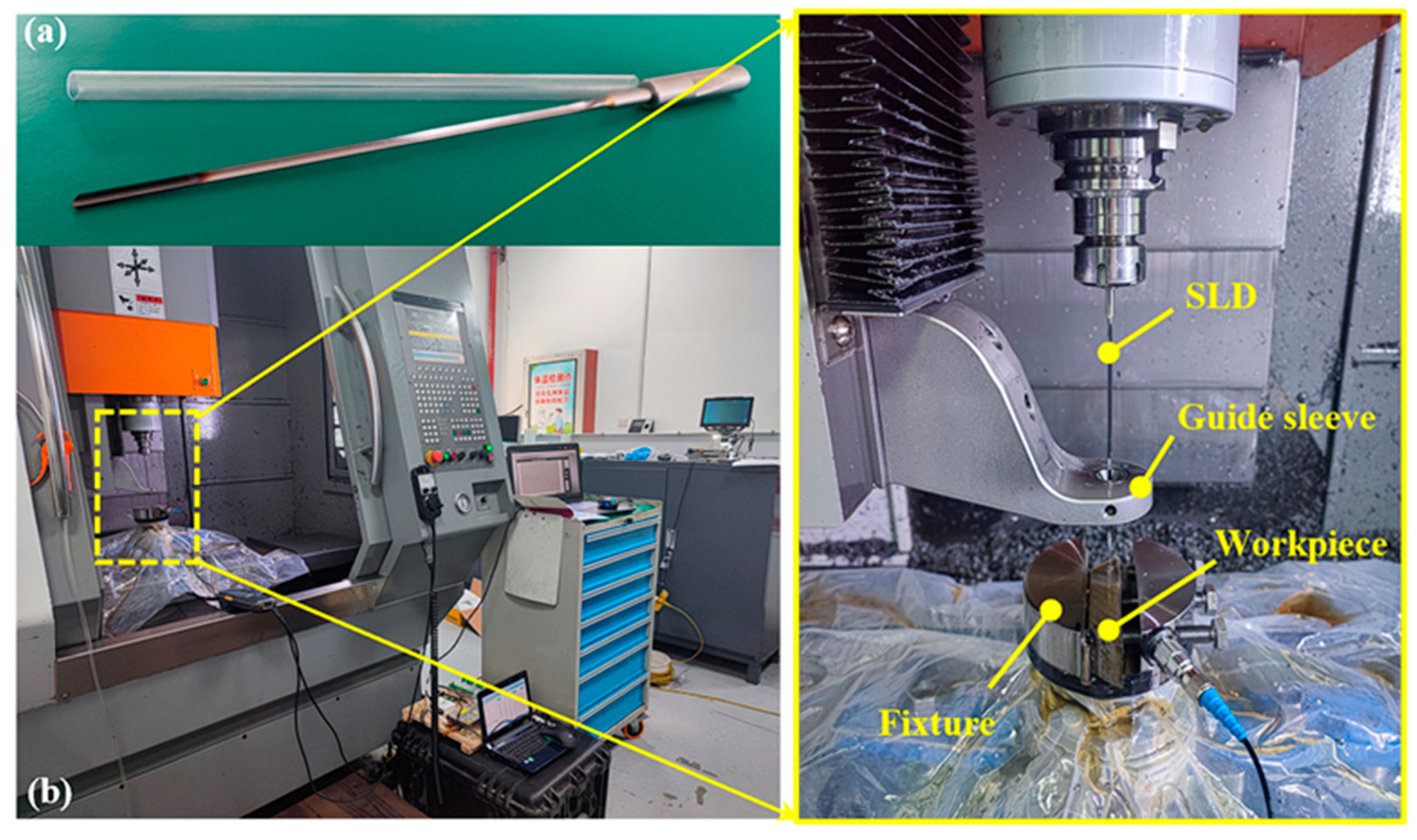
For this experiment, the solid cemented carbide tool SLD produced by Xinyixiu Tucker Machinery Co., Ltd. in Suzhou, China was selected, with the specification model being Ø 3.02 × 200-L in the SH10-51 series, as shown in
Figure 1a. Based on the product parameter table, the recommended parameters for processing nickel-based alloys are as follows: the allowable range of cutting speed is 25–60 m/min, and the allowable range of feed rate is 0.008–0.0110 mm/rev. In deep-hole machining, the oil pressure of the cutting fluid plays a significant role in the cooling of the cutting tool and the removal of chips during the machining process. However, in this experiment, the influence of cutting fluid pressure on the cutting process was not considered. Therefore, the maximum value of cutting fluid that the machine tool could provide was directly selected to ensure the consistency of all tests. Cutting oil is a special cutting oil for deep-hole processing provided by machine tool manufacturers. The SLD features an asymmetric structure, positioned and guided entirely by the constraints of guide strips and their contact with the machined hole wall. During the initial drilling stage, a floating guide bushing with a diameter of 3.025 mm is employed to ensure the accuracy and stability of deep-hole drilling. At this phase, the SLD relies solely on the guide bushing for positioning, constituting an incomplete guidance stage. To prevent drill bit deviation, reduce vibrations under incomplete guidance, and avoid edge chipping or even drill fracture caused by uneven or excessive forces within a short period, a low feed rate of 20 mm/min is applied at the initial stage of each hole. Only after drilling to a depth of 5 mm are the machining parameters specified in
Table 1 adopted. This approach enhances the surface quality of the drilled hole during the entry phase and extends the tool service life.
All drilling experiments were conducted on a Ligong LG-T640 vertical drilling machining center in Suzhou, China, as shown in
Figure 1b. The machine tool is equipped with a 1.8 kW feed motor, offering a feed speed range of 1 to 1080 mm/min with stepless speed regulation. The spindle is controlled by an encoder, driven by a 5.5 kW-rated power main motor that reaches a maximum speed of 8000 r/min. It is capable of machining holes with diameters ranging from Ø 1 to 12.7 mm and a maximum depth of 200 mm.
The base material for the drilling experiments was a cylindrical nickel-based alloy bar with a diameter of Ø 100 mm. For convenient clamping during machining, the bar was cut into rectangular prisms with dimensions of 20 mm × 90 mm × 30 mm, and the drilling depth was set to 28 mm. In addition to containing 51.4% Ni as the matrix element, the material includes dozens of alloying elements, with relevant chemical compositions listed in
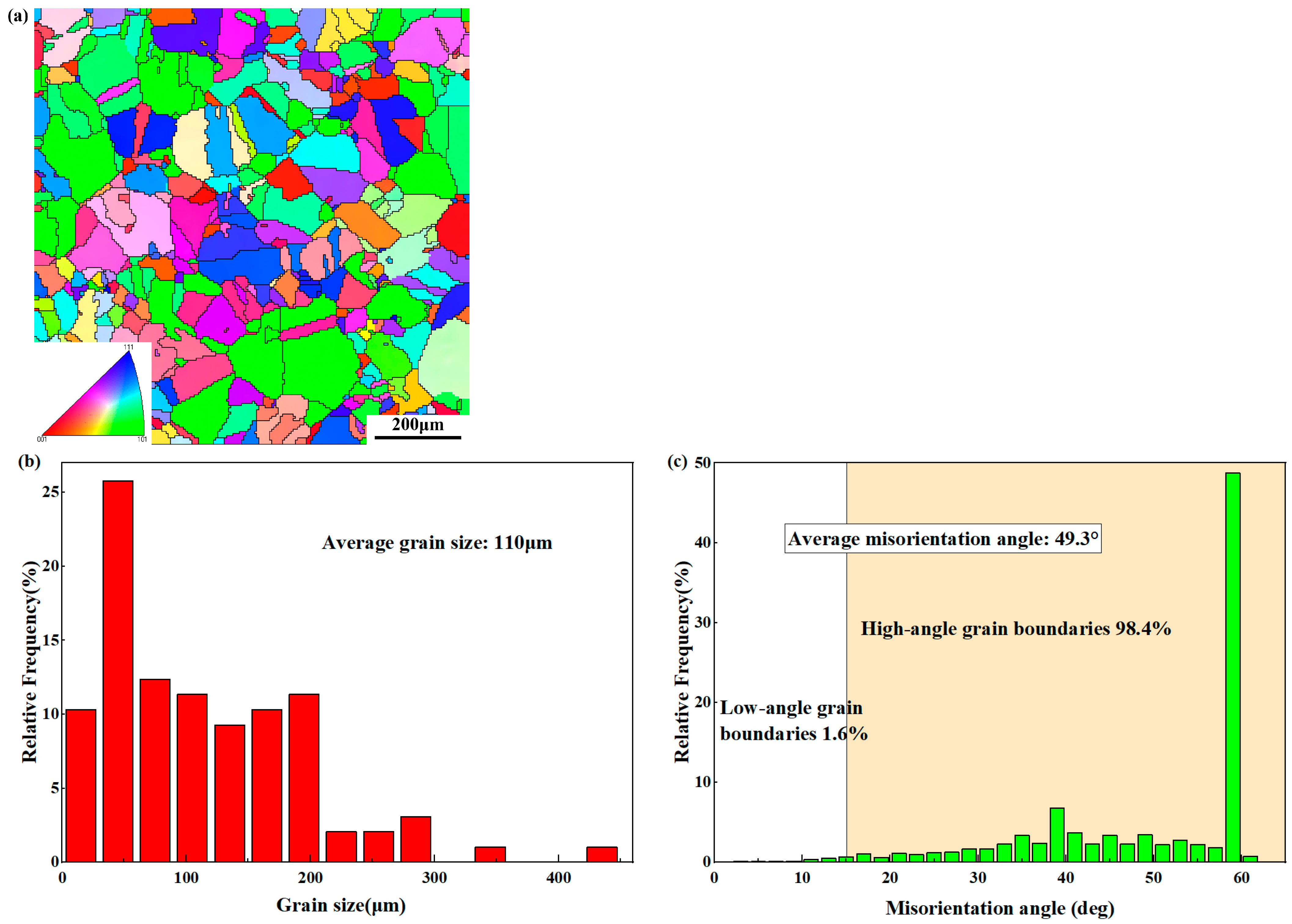
Table 2. The substrate exhibits a uniform grain distribution, with an average grain size of approximately 110 μm, which is relatively large and homogeneous. The microstructure is shown in
Figure 2a. High-angle grain boundaries (HAGBs) have misorientation angles greater than 15°, while low-angle grain boundaries (LAGBs) have misorientation angles between 2° and 15° [
40]. The average misorientation is 49.3°, indicating a high proportion of high-angle grain boundaries. The main mechanical properties of the base material, provided by the manufacturer, are listed in
Table 3.
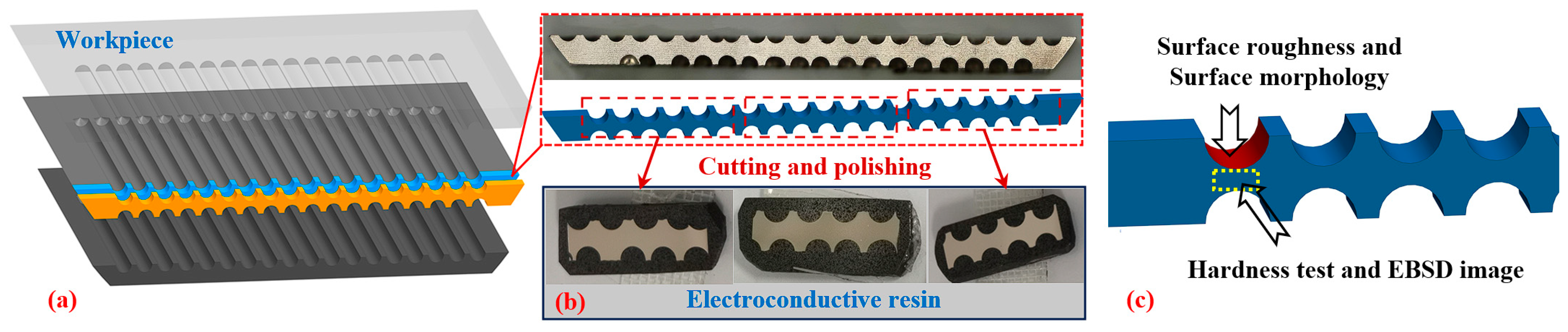
To evaluate the surface integrity of the machined holes, a electrical discharge machine (G43S Wire Cut EDM, Ching Hung Machinery & Electric Industrial Co., Ltd., Taiwan) with slow wire-feeding was used to cut along the axial direction of the drilled hole, exposing the machined surface. The schematic of the drilled and cut part is shown in
Figure 3. First, a roughness tester was used to measure the roughness at five points along the hole’s central axis at 5 mm intervals, with the average value taken as the surface roughness under the given drilling conditions. During this process, the entry and exit zones were avoided to minimize the influence of machining processes (such as hole entry and tool retraction) on surface integrity and reduce measurement errors. The plate-shaped samples were cut into small pieces, subjected to planar argon ion polishing, and inlaid with resin powder. The microstructure of the samples was tested on an SEM (Thermo Scientific Apreo 2C, Thermo Fisher Scientific Inc., Waltham, MA, USA) equipped with an EBSD detector. Crystallographic orientation characterization was carried out in the 70 μm × 15 μm area near the drilling surface at a scanning voltage of 20 kV and a step size of 0.06 μm. The collected test data were analyzed using the EBSD data processing software Channel 5 from HKL Technology (Oxford, UK). In addition, in order to evaluate the mechanical properties of the hole surface and subsurface, the average Young’s modulus and hardness of the subsurface of the machined holes were recorded using a nanoindentation instrument (Agilent G200, Keysight Technologies Inc., Santa Rosa, CA, USA). The Berkovich indenter was selected to apply the load and indentation depth on the substrate surface. The static load was 4 mN, and the nanohardness of the substrate was 4.4 GPa. The nanohardness between 45 μm and the radial distance from the hole surface was measured by the quasi-static loading method. The surface roughness and microhardness parameters were measured three times, and the average values were taken. The surface morphology was observed using the VHX-X1 ultra-depth-of-field microscope (Keyence Corporation, Osaka, Japan).
The experimental results were primarily evaluated from seven aspects: grain size, grain misorientation, grain orientation and deformation, surface morphology, surface roughness, hardness, plastic deformation layer (PDL), and recrystallization layer (RL). The surface roughness values were represented by the average of three holes, while for other aspects, the hole closest to the average value was selected for observation. In most cases, single-factor results were chosen for analysis and comparison.
3. Results and Discussion
3.1. Grain Size
The EBSD test scanning area has a depth of 70 μm and a width of 15 μm. Considering the irregular sample edge, the machined surface within the scanning area was flattened as much as possible.
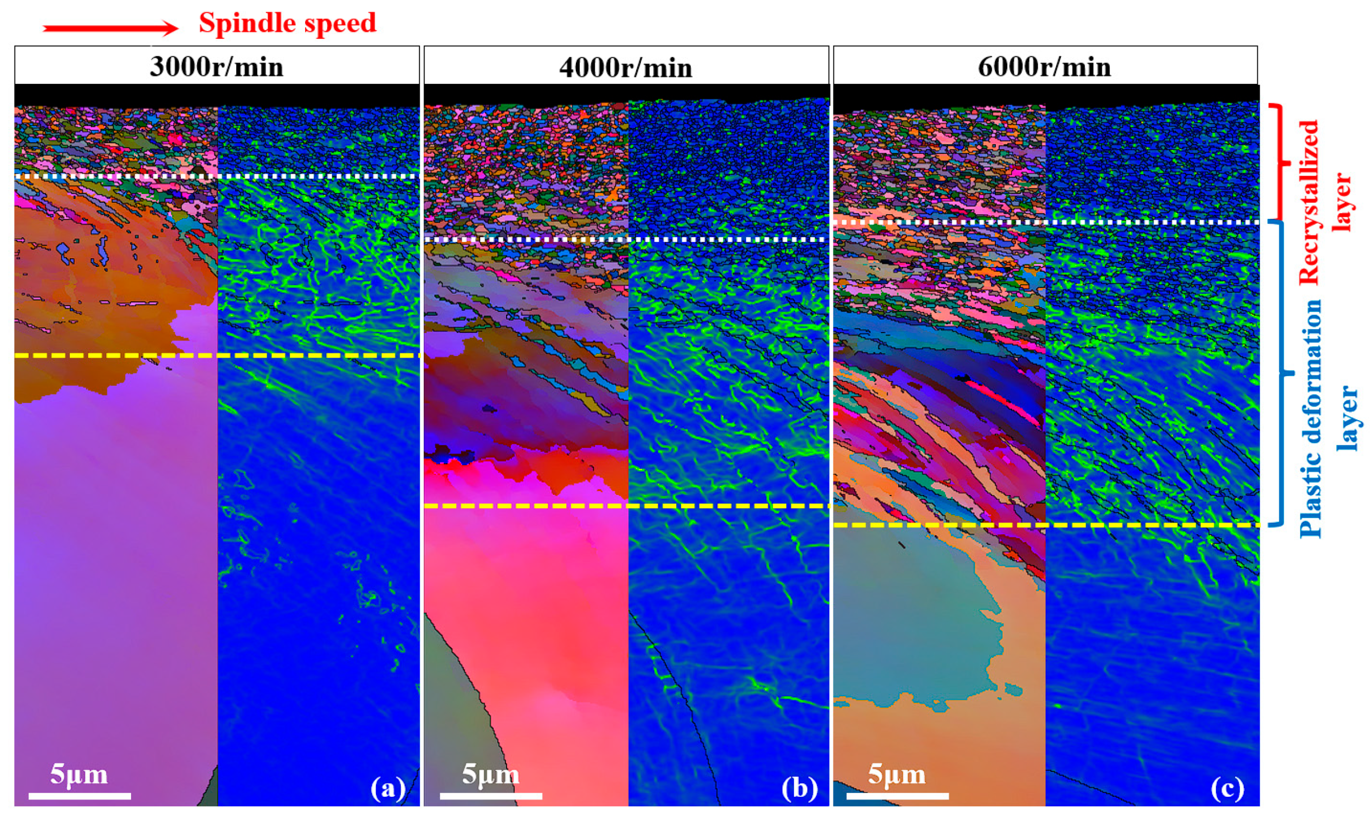
Figure 4 illustrates the microstructural changes and grain gradient distribution at different spindle speeds. Based on the material microstructure gradient, the borehole surface layer consists of two distinct regions: the recrystallization layer and the plastic deformation layer. The recrystallized layer, characterized by a uniform fine equiaxed crystal structure, is adjacent to the machined surface. This layer forms due to severe plastic deformation during drilling, which generates high-density dislocations within grains. Concurrently, drilling-induced high temperatures trigger the dynamic recrystallization of the deformed material, leading to grain refinement. The plastic deformation layer lies beneath the recrystallization layer, with the deformation degree decreasing with depth. The grain structure in this region exhibits a distinct streamline distribution, attributed to shear slip during machining. In the plastic deformation layer, grains elongate along the cutting direction, and the degree of grain refinement decreases. Material deformation gradually diminishes from the machined surface to the interior.
The quantitative analysis of the recrystallization layer thickness, plastic deformation layer thickness beneath the machined surface, and corresponding grain size reveals the effect of spindle speed on these layers. As shown in
Figure 4a, at a spindle speed of 3000 r/min, the recrystallization layer thickness is approximately 3.41 μm, and the plastic deformation layer thickness is approximately 8.84 μm. With increasing spindle speed, both the recrystallization layer and plastic deformation layer thicknesses increase systematically. At a spindle speed of 6000 r/min (
Figure 4c), the recrystallization layer thickness reaches 5.77 μm, and the plastic deformation layer thickness reaches 14.32 μm. This phenomenon arises because higher spindle speeds enhance mechanical–thermal loading. At a constant feed rate, increasing the spindle speed converts most mechanical energy during cutting into thermal energy, causing a rapid rise in workpiece surface temperature. Higher temperatures provide the necessary driving force for recrystallization, as this process requires specific temperatures to activate atomic diffusion and rearrangement. When the temperature exceeds the material’s recrystallization threshold, the recrystallization process initiates, leading to a gradual thickening of the recrystallization layer. Additionally, an increase in spindle speed simultaneously enhances the degree and rate of material deformation. During cutting, the workpiece material undergoes shear deformation under the action of the cutting tool. At high cutting speeds, dynamic recrystallization progresses sufficiently to counteract recrystallized layer thickening [
41].
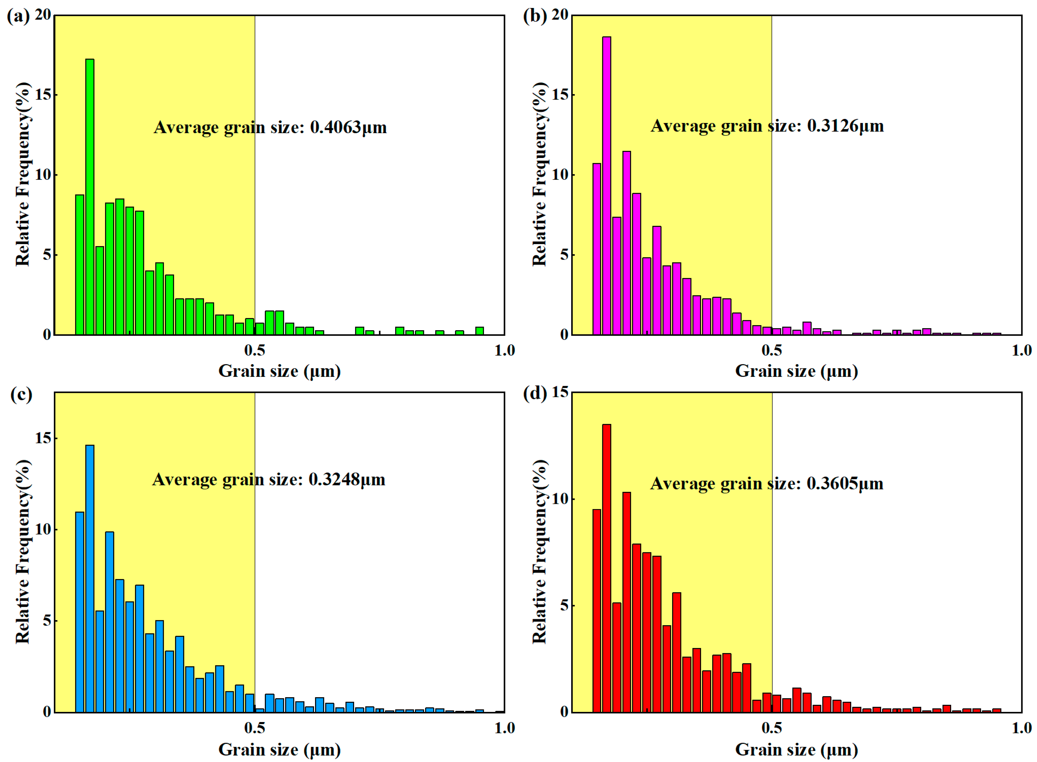
Figure 5 shows the size distribution of grains smaller than 1 μm at a depth of 35 μm from the machined surface at different spindle speeds. It can be clearly seen that, regardless of the spindle speed, during the drilling process, the average 110 μm grains of the matrix undergo large-area grain refinement near the machined surface.
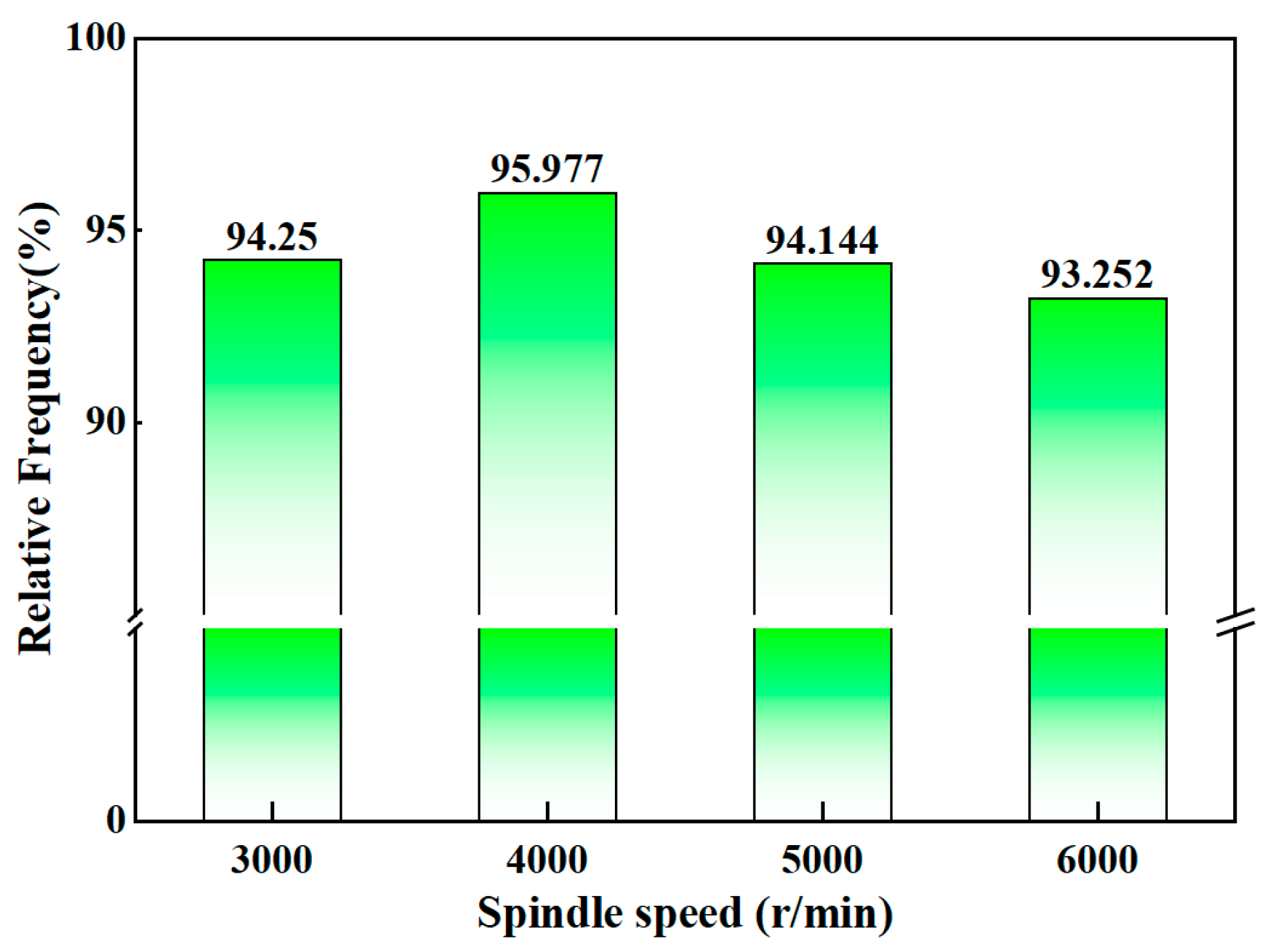
Figure 6 shows the proportion distribution of grains with diameters less than 0.5 μm at a depth of 35 μm from the machined surface at different spindle speeds, all accounting for more than 90%. It can be seen that with the increase in spindle speed, the proportion of grains smaller than 0.5 μm first rises and then decreases. This is because the increase in spindle speed leads to an increase in the temperature of the machined surface, which enables the grain refinement to proceed more fully. Therefore, the grain refinement phenomenon is more severe, and the grain size gradually decreases. However, with the further increase in the spindle speed, recrystallization and grain growth reach a dynamic equilibrium. Therefore, the size of the refined grains increases, resulting in a decrease in the proportion of grains with a diameter less than 0.5 μm when the statistical area is constant.
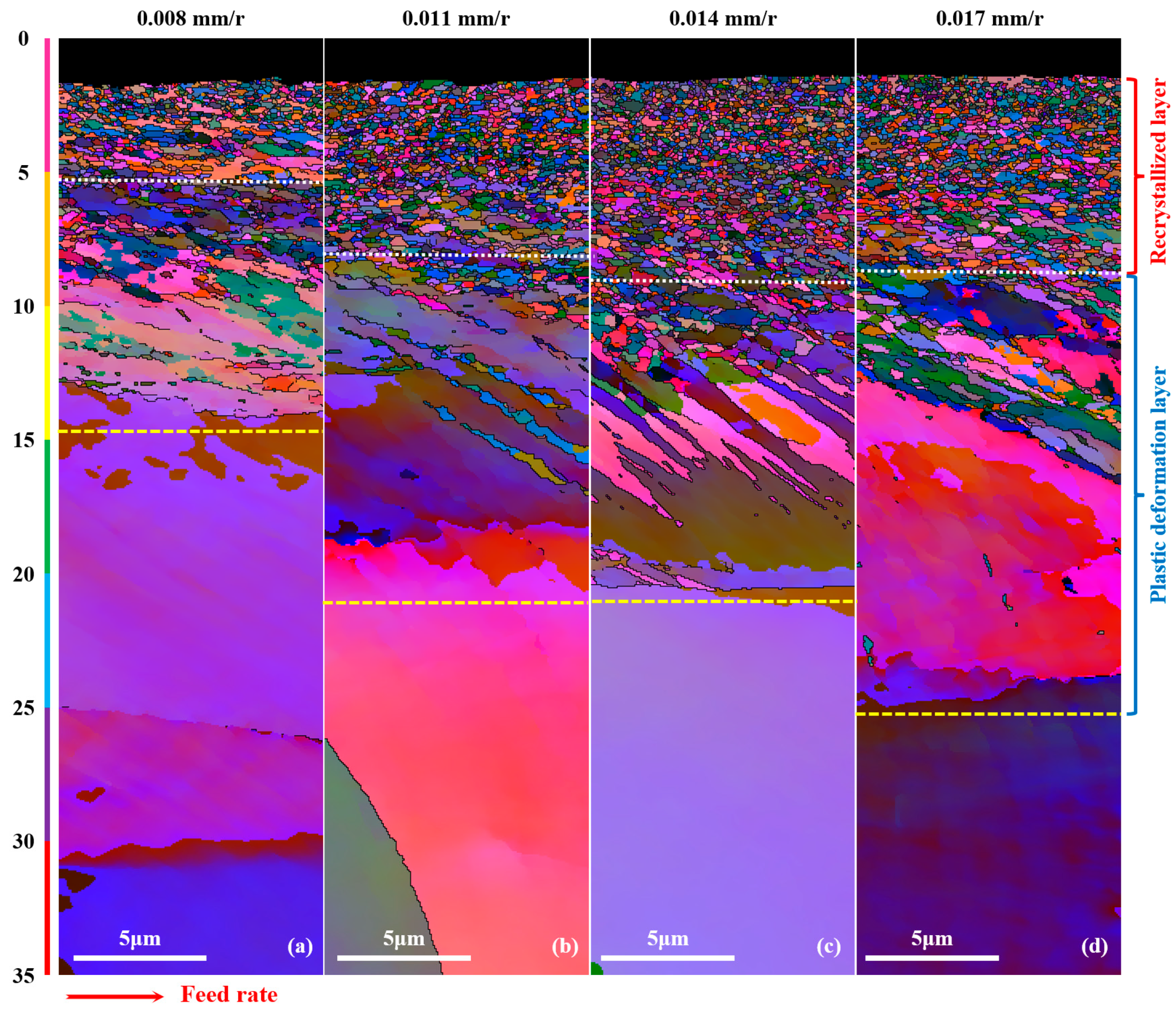
The variations in grain microstructure and gradient distribution under different feed rates are shown in
Figure 7. The recrystallization layer and the plastic deformation layer can be clearly observed in the area 35 μm away from the machined surface. When the spindle speed was constant at 4000 r/min, as the feed rate increased from 0.008 mm/rev to 0.017 mm/rev, the thickness of the recrystallization layer increased from 3.715 μm to 7.71 μm and then thinned to 7.31 μm, and the thickness of the plastic deformation layer increased from 9.37 μm to 16.54 μm.
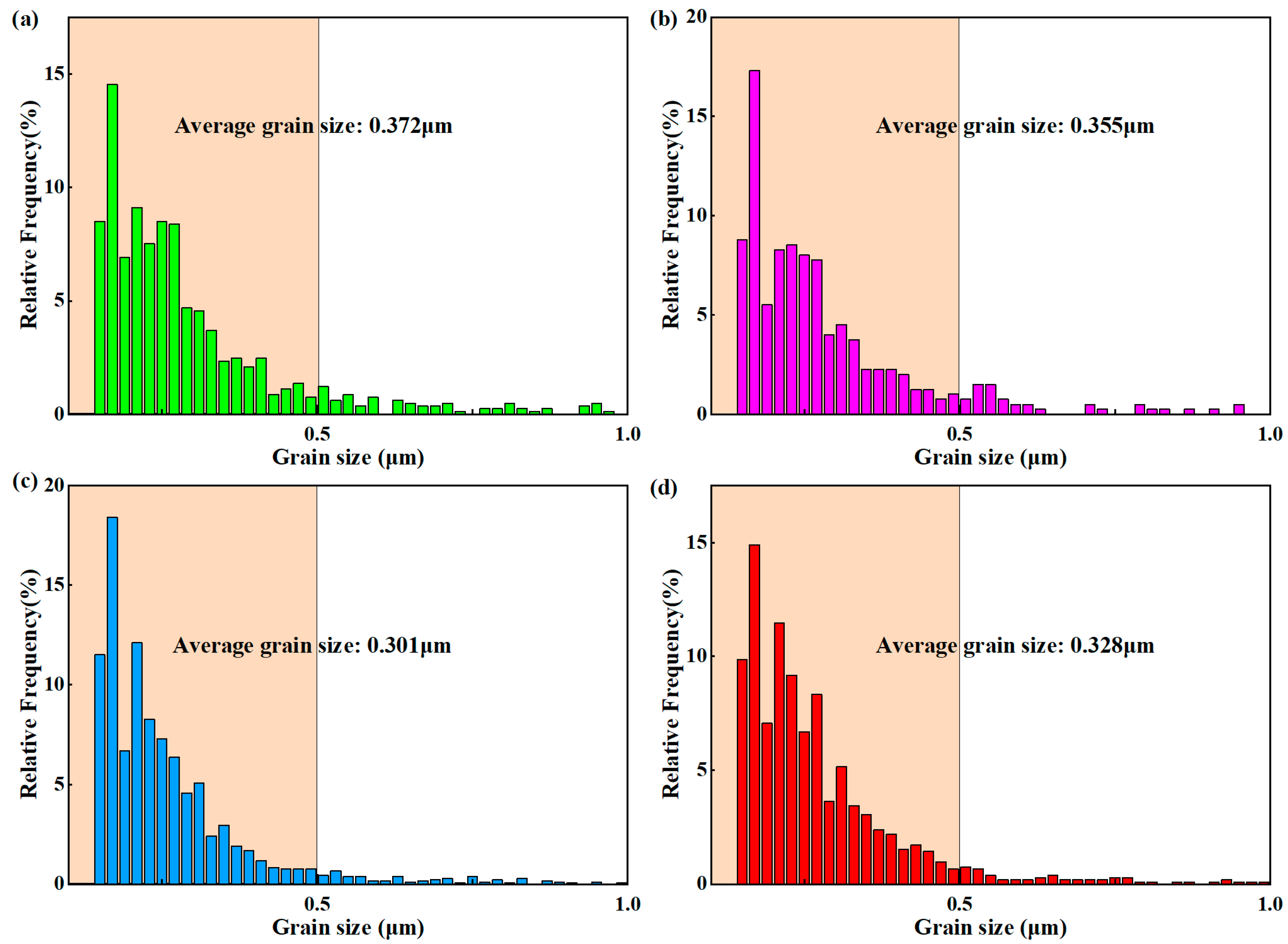
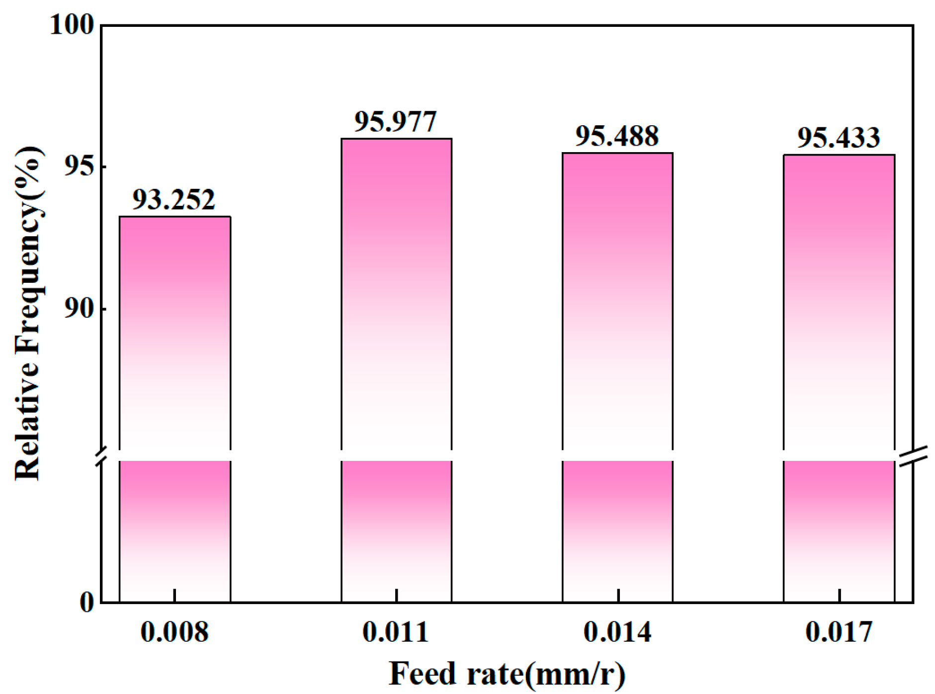
Figure 8 shows the size distribution and average grain size of grains smaller than 1 μm at a depth of 35 μm from the machined surface under different feed rates. With the increase in the feed rate, the proportion of small-sized grains in the selected area increased from 93% to 95%, showing an overall trend of first increasing and then slightly decreasing. The average grain size decreased from 0.370 μm to 0.301 μm and then, subsequently, increased slightly.
Figure 9 is a statistical chart of the proportion of grains with a diameter of less than 0.5 μm under different feed rates. It is obvious that all of them exceed 90%. With the increase in the feed rate, the proportion of small grains increases to 95% and then gradually stabilizes. Considering that the spindle speed is the same, as the feed rate increases, the temperature of the machined surface gradually increases, and the grain refinement is more complete. However, as the feed rate further increases, the temperature accumulation on the machined surface tends to stabilize, and recrystallization and grain growth reach a dynamic equilibrium, so they will not continue to increase.
3.2. Grain Misorientation
During the process of gun drilling for nickel-based alloys, thermal loads and mechanical loads can cause plastic deformation in the surface layer of the workpiece, among which the distribution of grain orientation differences is one of the typical characteristics of plastic deformation. When the spindle speed is 3000 r/min and the feed rate is 0.011 mm/rev, the angular distribution of the grain boundary orientation difference is shown in
Figure 10a. It can be seen that in the original state of the workpiece, the proportion of LAGB is 43.6%. The EBSD scanning image was uniformly divided into three parts along the depth direction, and the depth of each part was 11 μm. The distribution of local orientation angles in the three interfaces was quantitatively statistically analyzed, as shown in
Figure 10b–d. In the first part, the local orientation angles are concentrated between 0° and 1°, and the proportion of local orientation angles less than 0.5° is 98%. This structure is an important sign of work hardening and is related to the local temperature rise limitation caused by the low thermal conductivity of nickel-based alloys. The main cause is that this part is close to the processing surface and is subject to the effects of cutting heat and tool extrusion force, etc., resulting in severe plastic deformation and thermo-force coupling effects. Cutting processing causes severe plastic deformation, and dislocations rapidly proliferate to form tangles. However, due to insufficient dynamic recovery time, dislocations form sub-grain boundaries (orientation difference <0.5°) through dynamic recovery, which is manifested as small-angle grain boundaries (LAGBs) accounting for up to 98%. Meanwhile, the cutting heat accumulates locally in the nickel-based alloy with low thermal conductivity. The surface temperature approaches the critical value of dynamic recrystallization, but the short-term thermal effect inhibits the grain boundary migration and strengthens the subcrystalline structure. In the second part, as the strain rate decreases and the temperature gradient reduces, dynamic recrystallization gradually activates. Dislocations reorganize to form large-angle grain boundaries (HAGBs), and the orientation differences are concentrated in the range of 12° to 25°. In the third part, the local orientation difference accumulates at approximately 1.5°, mainly because the strain further decreases, the heat effect weakens, the dynamic recovery dominates the deformation, the dislocation density decreases, and the distribution tends to be uniform, forming a metastable subcrystalline structure with an orientation difference of approximately 1.5°. When the deep temperature does not reach the recrystallization threshold, dislocations form more stable low-angle interfaces through local sliding and recombination. To sum up, the orientation difference distribution at different depths reflects the hierarchical evolution of strain gradient, thermal activation degree, and dynamic recovery/recrystallization competition. Its mechanism is closely related to the energy input and heat dissipation conditions caused by processing parameters (spindle speed and feed rate).
Metal removal rate (MRR) is the core parameter for measuring the efficiency of gun drilling in processing nickel-based alloys; its variation has a significant impact on the microstructure evolution of the material’s surface layer. As shown in
Figure 11, within the depth range of 35 μm from the machined surface and with the increase in MRR, the average grain size and the proportion of small-angle grain boundaries (LAGBs) show a synchronous downward trend. This is mainly attributed to the thermal-force coupling effect caused by the intense cutting conditions under high MRR: On the one hand, the increase in metal removal rate is accompanied by a significant increase in cutting force and cutting heat, and the dislocation density inside the material rises sharply due to intense plastic deformation; although the increase in cutting temperature can promote dynamic recrystallization nucleation, the high strain rate and rapid chip removal accelerate heat loss and inhibit the continuous growth of recrystallized grains, and at the same time, the high-density dislocation entanglement further hinders grain boundary migration, ultimately promoting the further refinement of the average grain size. On the other hand, under the synergistic effect of high temperature and high strain, proliferative dislocations form large-angle grain boundaries (HAGBs) through dynamic recovery and recombination, leading to the transformation of the original LAGBs (such as sub-grain boundaries) into HAGBs. Furthermore, the newly formed grain boundaries during the grain refinement process tend to present large-angle characteristics due to the cumulative effect of orientation differences, which jointly leads to the decrease in the proportion of LAGBs from about 50% initially to about 30%. The results show that by regulating the MRR, the synergistic control of grain refinement and grain boundary structure optimization in the surface layer of nickel-based alloy processing can be achieved, providing a theoretical basis for balancing processing efficiency and surface integrity.
3.3. Grain Orientation and Deformation
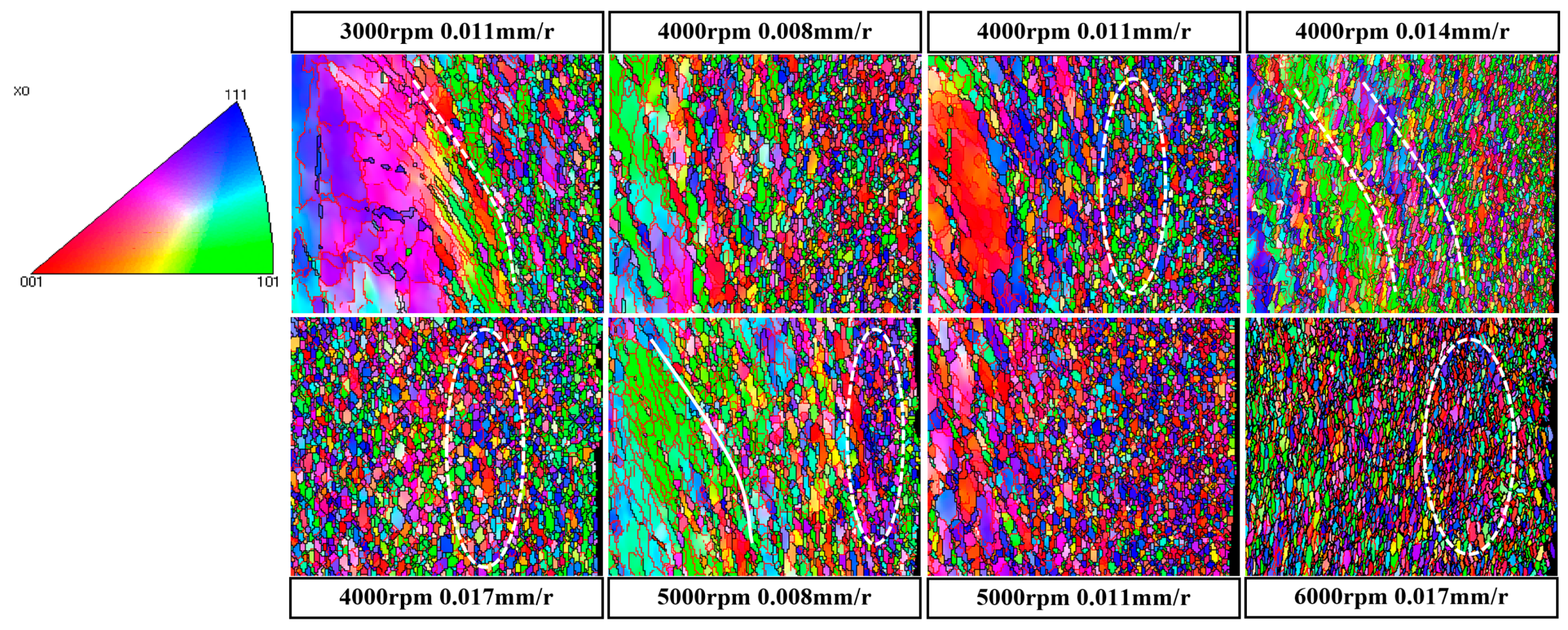
The detailed EBSD micrographs obtained from the EBSD analysis are shown in
Figure 12, with the right edge of each photograph being the machined surface. It can be seen from the figure that after the drilling process, it is found that the recrystallized layer of nickel-based superalloy shows a grain-layered distribution in the underground of the drilling surface. Combined with the subsequent roughness results, it is found that the holes with good processing surface quality mainly contain <111> grains close to the processing surface; on the contrary, <001> grain content is high. Due to the combined effects of mechanical deformation and thermal deformation, the deformation and recrystallization of grains are significant at higher metal removal rates. The content of deformed and recrystallized grains is low after drilling at 3000 r/min cutting speed due to a low strain rate and temperature. Under the processing parameter combination of cutting speed 6000 r/min and feed rate 0.017 mm/rev, the recrystallized layer mainly consists of <101> grains.
3.4. Surface Morphology
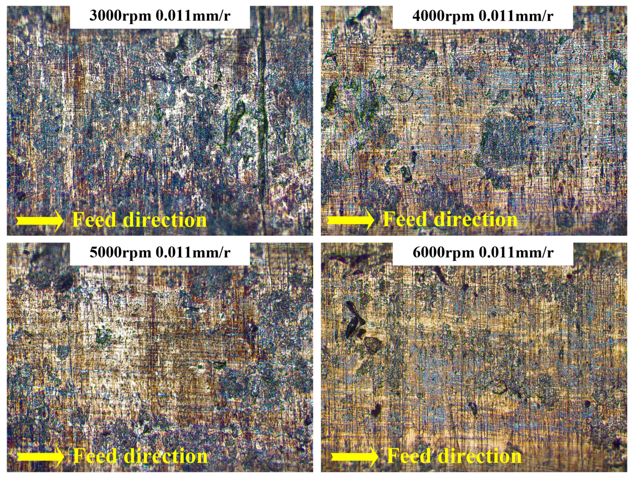
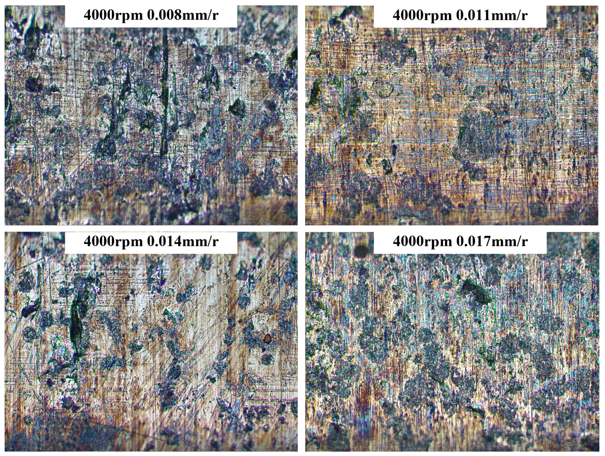
Defects such as feed marks, surface tears, and grooves are key indicators of hole wall surface integrity in nickel-based alloys processed by gun drilling, with their morphological characteristics directly influencing workpiece fatigue performance and service life. The surface morphologies of workpieces under different drilling parameters are shown in
Figure 13 and
Figure 14 (samples collected from the stable machining zone midsection). Results demonstrate that drilling parameters significantly regulate surface defect evolution. When spindle speed increases from 3000 r/min to 6000 r/min (at a fixed feed rate), the density of large grooves and the pit count decrease, and the machined surface becomes progressively smoother. This occurs because high spindle speeds trigger thermal softening: continuous cutting zone temperature accumulation promotes dynamic recrystallization and homogenizes plastic deformation, thereby inhibiting brittle fracture-dominated groove formation. At a medium spindle speed (4000 r/min), the pit area increases due to intensified adhesive wear and material adhesion–tear mechanisms. As the spindle speed further increases to 6000 r/min, the cumulative temperature improves material fluidity, leading to pit edge smoothing.
At fixed spindle speeds, increasing the feed rate from 0.008 mm/rev to 0.017 mm/rev induces a dual-stage surface morphology evolution of “improvement-deterioration”: In the low-feed stage (≤0.011 mm/rev), thin chip thickness and minimal cutting force fluctuation reduce groove density and pit count; in the high-feed stage (≥0.014 mm/rev), an abrupt chip thickness increase causes thermoplastic shear instability via local stress concentration, resulting in a pit count rebound. Pit area exhibits a non-monotonic trend (first increasing, then decreasing) due to shear zone expansion. This evolution confirms the thermal-force coupling mechanism: low-speed/low-feed conditions promote mechanically dominated brittle stripping, while high-speed/high-feed conditions regulate surface integrity through dynamic recrystallization and oxide film formation—though overheating may induce oxidation discoloration. The optimized process window (spindle speed 4000–5000 r/min, feed rate 0.011–0.014 mm/rev) synergistically suppresses grooves and pits, providing theoretical support for the low-damage manufacturing of aerospace high-temperature components.
3.5. Surface Roughness
The roughness of the machined surface is of great significance for the surface interaction between different parts, as it affects the stiffness, fatigue strength, wear resistance, and sealing performance of the parts. The surface roughness Ra represents the average value of the absolute distance between each point on the actual contour to be measured and the midline of the contour within the sampling length. The surface roughness Sa represents the average deviation value of the height of the sampled surface. The smaller the Sa value is, the smoother the surface is. Both can be used to evaluate surface roughness.
Figure 15 shows the surface roughness under different drilling parameters. Obviously, the variation laws of the two roughnesses are not the same. Considering that Sa is measured by three-dimensional scanning of the surface and calculates the average height deviation of all points, it can describe the microscopic geometric shape of the surface more comprehensively. Especially for processing surfaces with complex three-dimensional shapes, Sa can provide more abundant information than Ra. Therefore, the variation law of Sa is analyzed emphatically.
Figure 15a shows the influence of drilling speed on surface roughness. It is worth noting that when the feed rate is 0.11 mm/rev, the drilling speed range is 3000–6000 r/min, and the surface roughness Sa is between 0.42 μm and 0.92 μm, first decreasing and then increasing. This is because when the drilling speed is low, relatively less cutting heat is generated. At this point, the cutting heat causes a slight softening of the surface of the nickel-based alloy material to a certain extent. After the material softens, it can be cut more easily by the cutting tool. Moreover, under the action of the cutting tool, the plastic flow of the material becomes more uniform, which is conducive to obtaining a relatively smooth processing surface, thereby reducing the surface roughness. Afterwards, with the continuous increase in the drilling speed, the cutting heat increased sharply. Excessive cutting heat can cause significant thermal deformation in nickel-based alloy materials. This kind of thermal deformation may cause local expansion, contraction, or distortion of the material near the processing surface, destroying the surface flatness and thereby increasing the surface roughness. In addition, a higher drilling speed will cause changes in the cutting force, including an increase in the magnitude of the cutting force and instability in the direction of the cutting force. These changes in cutting force can cause vibration in the processing system. Vibration will cause periodic changes in the relative position between the tool and the workpiece, thereby forming wavy marks on the machined surface and increasing the surface roughness. This can be confirmed in the surface morphology in the previous section.
Figure 15b illustrates the effect of feed rate on surface roughness. As the feed rate increases, the machined surface roughness first decreases and then gradually increases. At low feed rates, roughness decreases due to three primary mechanisms: (1) gentle tool-material contact enables precise cutting edge engagement, promoting a self-sharpening effect that maintains optimal edge condition; (2) stable, low-magnitude cutting forces facilitate smooth material cutting and uniform plastic deformation, conducive to forming a smooth surface; and (3) chips discharge smoothly without interfering with the machining process. As the feed rate increases, roughness rises due to dual effects: (1) elevated cutting forces induce severe, non-uniform material deformation, leading to surface undulation and tearing; (2) accelerated tool wear blunts the cutting edge, deteriorating cutting quality and increasing material extrusion-scraping, which roughens the surface. Concurrently, higher chip generation rates and volumes, if not discharged promptly, accumulate to cause surface scratches and compression, further increasing roughness. Notably, at a spindle speed of 4000 r/min and feed rate of 0.011 mm/rev, surface roughness Sa attains the minimum value, confirming that this parameter combination yields optimal surface quality. Comparative analysis shows the feed rate’s influence on surface roughness is significantly less than that of spindle speed.
3.6. Local Hardness
The subsurface properties of the machined surface are evaluated by nanohardness measurement. Samples were prepared using fast wire cutting technology and mechanical polishing, and the microhardness was measured at certain intervals along the radial direction on the cross-section of the drilling surface.
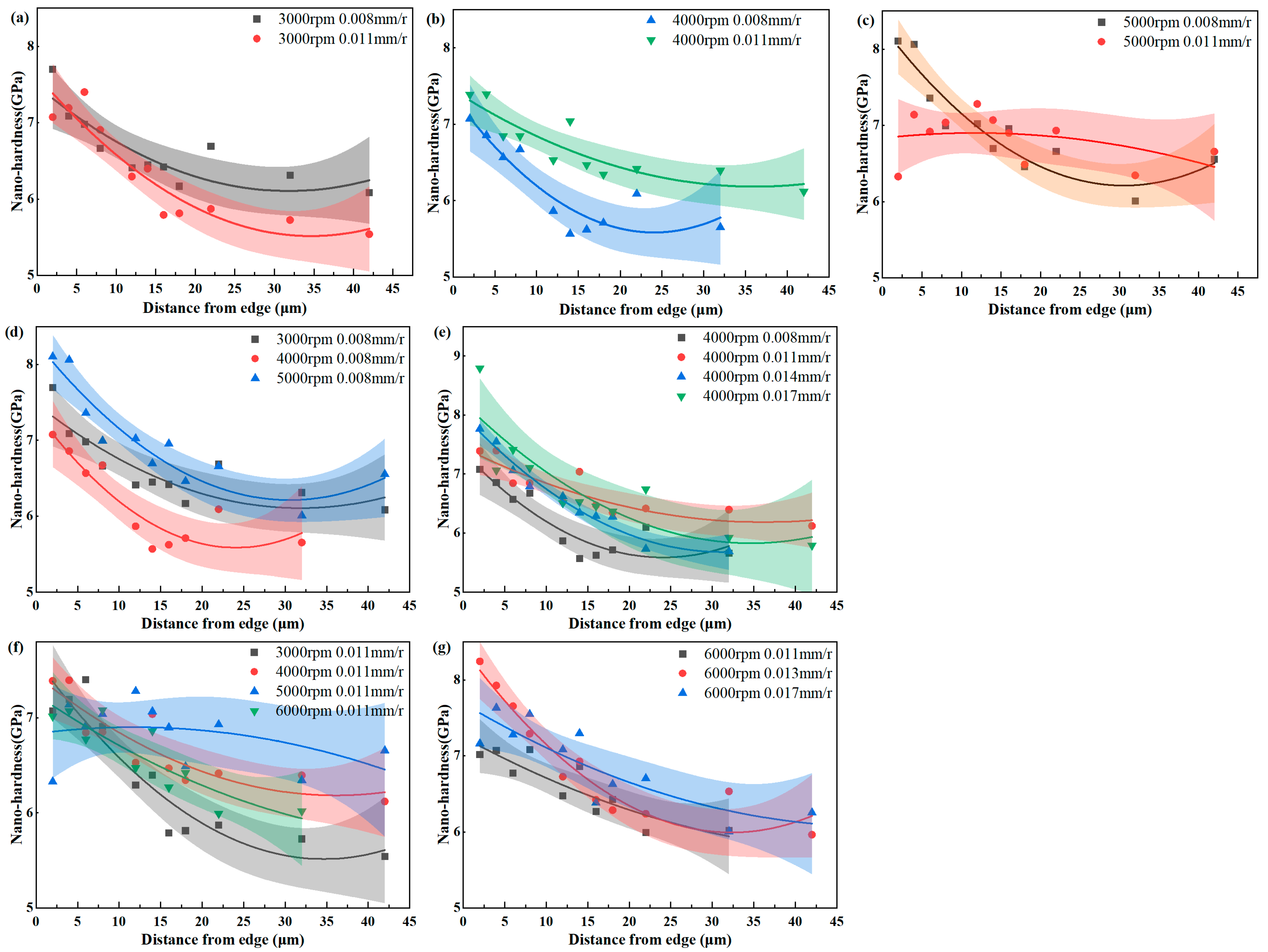
Figure 16 shows the positions of the nanoindentation under different drilling processing parameters, and the related hardness values are shown in
Figure 17. The polynomial fitting curve and confidence interval are presented in the figure.
Clearly, in nearly all experimental groups, the nanohardness adjacent to the machined surface exceeded that of the matrix. With increasing distance from the machined surface, hardness exhibited a decreasing trend, stabilizing at approximately 6 GPa—consistent with the matrix hardness. The high-hardness zone near the borehole edge results from machining-induced strain hardening, referred to as the MAZ. As discussed in
Section 3.1, along the depth direction of the machined surface, recrystallization occurs first, followed by plastic deformation at greater depths. This high hardness primarily originates from the fine grain structure and high dislocation density within the recrystallized region, defining the hardness peak. The plastic deformation layer features a dislocation density higher than the matrix but lower than the recrystallization layer, constituting the hardness transition zone. Both recrystallization and plastic deformation contribute to the hardening of the machined surface and subsurface layers.
Comparisons of
Figure 17a–c indicate that at low spindle speeds, different feed rates exhibit negligible influence on peak hardness, which remains within 7–7.5 GPa. As the spindle speed increases, the effect of feed rate on peak hardness becomes progressively significant. The machining parameter combination of 5000 r/min spindle speed and 0.008 mm/rev feed rate yields the most pronounced hardness peak from recrystallization, with plastic deformation effects aligning with low-speed trends.
Figure 17d,f demonstrate that at constant feed rates, the spindle speed exerts a more substantial impact on maximum hardness. The results in
Figure 17e,g confirm that at low spindle speeds, feed rate variations minimally affect surface and subsurface hardness. At high spindle speeds, feed rate significantly influences maximum hardness. Notably, a lower hardness at the borehole edge occurs at 5000 r/min spindle speed and 0.011 mm/rev feed rate, attributed to elevated processing temperatures causing thermal softening.
3.7. Plastic Deformation Layer (PDL) and Recrystallization Layer (RL)
The KAM images obtained through EBSD, combined with the measured nanoindentation hardness values, are helpful for distinguishing the machined-affected zone from the heat-affected zone. The machined-affected zone includes the plastic deformation zone and the recrystallization zone, and the heat-affected zone is the recrystallization zone. The nanohardness of unprocessed nickel-based alloys ranges from 5.5 to 6 GPa. Therefore, the area beneath the drilling surface where the nanohardness is higher than 6 GPa is regarded as the machined-affected area. However, it has been observed that some thermal softening caused by recrystallization phenomena occurs very close to the edge of the borehole, especially under high rotational speed and high feed rate conditions, where the thickness of the recrystallization layer is relatively significant. It is well known that the processing influence zone is the impact of mechanical deformation in any processing process, and heat accumulation is the main cause of the formation of the recrystallization zone. Spindle speed is the biggest influencing factor affecting the processing influence zone. During the drilling process of nickel-based alloys, when the spindle speed increases from 3000 r/min to 6000 r/min, the plastic deformation zone fluctuates significantly, but the recrystallization zone changes weakly, as shown in
Figure 18. This is because the low thermal conductivity of nickel-based alloys limits the heat distribution near the edge of the borehole, thereby forming a relatively stable thickness of the recrystallization zone. During the cutting process, both recrystallization and grain growth occur simultaneously, and a dynamic equilibrium is reached between them. When the RL reaches a certain thickness, the newly formed grains will consume part of the energy and atomic diffusion force used for recrystallization nucleation during the growth process, preventing the RL from thickening rapidly without limit.
Figure 18 illustrates that at a high feed rate of 0.011 mm/rev, the thickness of the MAZ first increases and then decreases with increasing spindle speed, reaching a maximum of over 50 μm. During the initial stage of spindle speed increase, cutting heat accumulates rapidly. However, the limited thermal conductivity of nickel-based alloys leads to decreased yield strength, promoting plastic deformation. Concurrently, fluctuations in cutting force induce complex material flow, thereby increasing the thickness of the plastic deformation zone. Simultaneously, work hardening continues to act, increasing dislocation density and restricting deformation to some extent—creating a competitive relationship between the two mechanisms. With further increases in spindle speed, the sharp rise in cutting heat amplifies the material’s thermal softening effect, causing a significant decrease in yield strength and a rapid expansion of the plastic deformation layer. This results in a pronounced change in plastic deformation layer thickness at 5000 r/min, as validated by multiple test sets. For the spindle speed 5000 r/min and feed rate 0.011 mm/rev combination, the cumulative mechanical–thermal load effect is significant, leading to a relatively thick plastic deformation layer. When spindle speed is further increased, high-speed chip ejection removes substantial heat, reducing the workpiece temperature and weakening the thermal softening effect. Consequently, dynamic recrystallization is inhibited, work hardening enhances material deformation resistance, and the plastic deformation zone thickness decreases accordingly.
At a low feed rate of 0.008 mm/rev, the thickness of the MAZ first decreases and then increases with increasing spindle speed, ranging from a minimum of 13 μm to a maximum of 54 μm. During the initial stage of spindle speed increase, although cutting heat generation rises, the poor thermal conductivity of nickel-based alloys restricts heat conduction and accumulation at relatively low speeds. The primary impact localizes to the machined surface region, inducing microstructural changes in the material. Dislocation rearrangement and recrystallization dominate the material deformation process, leading to a decrease in plastic deformation layer thickness due to reduced dislocation density and recrystallization-induced consumption. The recrystallization layer thickness also decreases moderately with advancing dynamic recrystallization.
With further increases in spindle speed, accumulated cutting heat causes a significant rise in material temperature, making the thermal softening effect dominant. At elevated temperatures, nickel-based alloys exhibit decreased yield strength and increased plasticity, facilitating easier tool cutting and enhancing material susceptibility to plastic deformation. Work-hardening-induced barriers to plastic deformation—such as dislocation structures—weaken, enabling the plastic deformation layer to re-expand and thicken rapidly. Here, thermal softening overrides work-hardening resistance, shifting material deformation behavior to be primarily governed by thermal softening. This results in extensive plastic deformation and a marked increase in plastic deformation layer thickness.
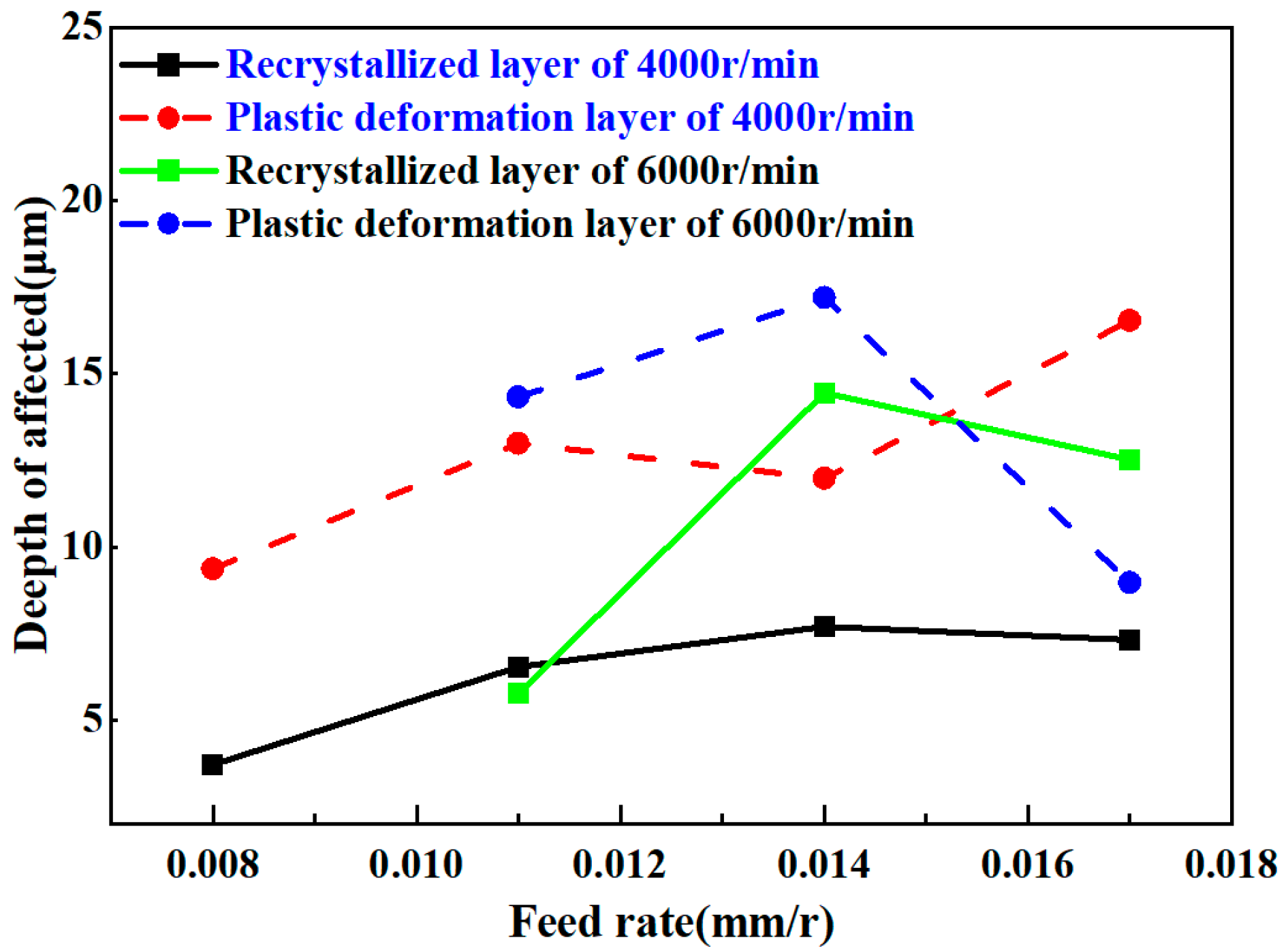
Figure 19 depicts the variation laws of the subsurface plastic deformation layer and recrystallization layer in nickel-based alloys during gun drilling at different processing rates. As illustrated, at a low spindle speed of 4000 r/min, the thicknesses of both the recrystallization layer and the plastic deformation layer increase systematically with rising feed rate. This trend arises from two primary mechanisms: First, increased feed rate enhances cutting force, intensifying the extrusion and shearing effects of the gun drill on the nickel-based alloy. This leads to severe grain deformation and extensive dislocation proliferation, providing abundant nucleation sites for recrystallization and promoting RL growth. Concurrently, material flow becomes more complex, involving more subsurface material in plastic deformation, thereby driving the continuous expansion of the plastic deformation layer. Second, intensified tool–workpiece friction coupled with intense material plastic deformation converts substantial mechanical energy to thermal energy. Sustained heat accumulation raises the subsurface temperature, supplying sufficient energy for recrystallization and further thickening both layers.
At a high spindle speed of 6000 r/min, the recrystallization layer and MAZ exhibit a trend of first increasing then decreasing with feed rate. In the initial stage, the high-speed rotating tool combined with elevated feed rate generates rapid cutting heat, synergizing with material plastic deformation. Cutting force exacerbates deformation and heat generation, creating optimal conditions for recrystallization. Alterations in material flow and heat distribution also contribute to the layer thickness increment. In the later stage, a further feed rate increase accelerates chip formation and high-speed ejection, removing substantial heat and causing a sharp drop in subsurface temperature. The disappearance of thermal softening, coupled with the loss of recrystallization driving force and the work-hardening-induced enhancement of material deformation resistance, hinders the continued expansion of both layers, thereby causing thickness reduction.
During the gun drilling of nickel-based alloys, the MRR correlates closely with subsurface PD and RL thickness variations.
Figure 20 shows the workpiece surface thickness for different MRRs. Experimental data show that as the MRR increases from 170 to 720 mm
3/min (corresponding to spindle speeds of 3000–6000 r/min and feed rates of 0.008–0.017 mm/rev), the RL thickness increases linearly from 4.81 to 12.7 ± 2.02 μm, while PDL thickness decreases significantly from 25.94 to 10.02 ± 10.61 μm. Given that PDL accounts for 50–85% of the total MAZ thickness, this reduction drives a decrease in total MAZ thickness from 30.75 to 22.76 ± 11.91 μm (95% confidence interval). This phenomenon stems from the competition between thermal and mechanical loads during gun drilling: At high MRR (e.g., 400 mm
3/min), cutting heat input surges (interface temperature estimated at 750–950 °C), exceeding the dynamic recrystallization activation energy threshold of nickel-based alloys. This promotes dislocation recombination and grain boundary migration, inducing continuous recrystallization and RL thickening. Concurrently, high strain rates accelerate dislocation proliferation, providing a nucleation driving force for recrystallization. Although increasing the MRR elevates cutting force, the high-temperature softening effect diminishes the plastic penetration depth of mechanical loads into the subsurface, confining dislocation slip and entanglement to the near-surface layer (<15 μm) and reducing dislocation density in deeper layers (>20 μm), thereby causing PDL thinning.
Based on these findings, processing parameter optimization requires balancing RL and PDL synergies as follows:
High surface integrity scenarios (e.g., aviation turbine blade cooling holes): Recommend medium MRR (280–380 mm3/min, corresponding to 4000–5000 r/min spindle speed and 0.008–0.011 mm/rev feed rate). This yields a total MAZ thickness of 17–40 μm with RL comprising 20–30%, achieving grain refinement (~0.35 μm average size) via moderate recrystallization to enhance fatigue resistance while preventing oxide layer thickening from overheating.
High-efficiency processing scenarios: Select high MRR (>380 mm3/min), which reduces MAZ thickness to ≤35 μm. However, this requires high-pressure internal cooling (>10 MPa) to suppress oxidation and discoloration.
4. Conclusions
This paper makes significant contributions to the understanding of the deep-hole drilling of nickel-based alloys by single-lip drill. It innovatively reveals the thermo-force coupling response law of the surface integrity of nickel-based alloy holes, which is a critical advancement in the field. By establishing the quantitative mapping relationship between process parameters and surface quality, the research provides a scientific basis for optimizing the deep-hole drilling process.
Notably, the study uncovers that the machined surface cross-section presents two distinct deformation zones, the RL and PDL, and demonstrates how spindle speed and feed rate significantly influence the gradient microstructure. The discovery that mechanical and thermal deformation dominance lead to different grain size and misorientation angle characteristics enriches the theoretical knowledge of material deformation during drilling. Additionally, the finding that the proportion of low-angle grain boundaries increases with depth due to grain recrystallization and that the grain orientation of deformed recrystallized grains follows a discernible pattern under combined high-temperature and mechanical deformation offers new insights into the microstructural evolution mechanism.
Regarding surface characteristics, the research clarifies the formation mechanism of grooves, pits, and the changing trend of surface roughness with spindle speed and feed rate. The significant impact of spindle speed on the peak hardness of the machined surface, along with the specific hardness change patterns under different speed and feed rate combinations, is also an important contribution.
Most importantly, the proposed optimization strategy of processing parameters based on different application scenarios is a practical innovation. For applications requiring high surface integrity, such as cooling holes in aviation turbine blades, the recommended medium MRR range provides a feasible solution to enhance fatigue resistance and obtain a low-defect surface. In high-efficiency processing scenarios, the suggestion of using a high MRR offers an effective way to reduce the processing-affected zone thickness, alleviate residual stress concentration, and optimize the crack propagation resistance of fatigue-sensitive areas. These strategies bridge the gap between theoretical research and engineering applications, greatly expanding the practical value of the research results.
It should be noted that the experiment did not consider the influence of cutting fluid pressure. Although the maximum value of cutting fluid provided by the machine tool was used to ensure test consistency, this does not imply the achievement of the highest possible cooling. Future research could explore the role of cutting fluid pressure in the deep-hole drilling process of nickel-based alloys to further improve the accuracy of process parameter optimization and the surface integrity of the machined parts.


