Article

Analysis of Flexible Bearing Load Under Various Torque Conditions

1
State Key Lab of Reliability and Intelligence of Electrical Equipment, Hebei University of Technology, Tianjin 300401, China
2
School of Mechanical Engineering, Hebei University of Technology, Tianjin 300401, China
3
School of Electrical Engineering, Hebei University of Technology, Tianjin 300401, China
4
School of Mechanical Engineering, Tianjin University of Technology, Tianjin 300384, China
*
Author to whom correspondence should be addressed.
Machines 2025, 13(7), 627; https://doi.org/10.3390/machines13070627
Submission received: 1 July 2025 / Revised: 13 July 2025 / Accepted: 16 July 2025 / Published: 21 July 2025
(This article belongs to the Special Issue Design and Manufacturing for Lightweight Components and Structures)

Abstract

This paper aims to develop a model for calculating the ball load of the thin-walled flexible bearing (FB) in a harmonic drive under various external torque conditions. The effect of the flexspline (FS) on the FB ball load is considered, and the equivalent ring is improved to calculate the ball load of the FB. Then, the accuracy of the proposed model in calculating the ball load is verified using a finite element analysis model. Finally, a fitting formula is obtained to rapidly evaluate the FB ball load via the geometrical parameters of the FB and the FS under various external torques. The results show that the FB ball load is mainly affected by the FB maximum radial deformation under low external torque. When subjected to heavy external torque, the maximum ball load is mainly affected by the FS’s geometric parameters.

1. Introduction

The harmonic drive (HD) has been widely used in robot joints, and has advantages such as small transmission error, large load capacity, and compact size [1,2,3]. As a complex rigid-flexible coupled transmission mechanism, shown in Figure 1, an HD is composed of flexible (flexspline (FS) and flexible bearing (FB)) and rigid (circular spline (CS) and cam) components [4,5]. FB is deformed by the action of the cam and then forms an interference fit with the FS. It is the core component of an HD. Experiments show that the wear of the FB can lead to HD failure [6,7]. Meanwhile, the ball load distribution is a key factor in determining the fatigue and wear of the FB [8,9]. However, it is difficult to directly observe and measure the deformation and force on the inside of an HD using an experiment. Therefore, the accurate calculation of the FB ball load is extremely important as a reference for analyzing subsequent wear and accuracy degradation.
The current research on the theoretical calculation of the FB ball load is mainly based on the Thin-walled Ring Theory [10,11,12]. The FB outer race is usually simplified as an equivalent ring with equal thickness. Then, the FB ball load is solved by establishing its relationship with the deformation of the equivalent ring. Some studies focus on the deformation of the equivalent ring under the action of the cam [13,14]. The FS is in contact with the FB outer race under the action of the cam. Thus, some scholars optimize an equivalent ring by simplifying the ring instead of the FS and consider the FS and FB outer race as a whole to improve the solution accuracy for FB ball load [15,16]. The FS is regarded as a ring in preceding studies, and the effect of the FS tooth is not considered. However, relevant studies show that the FS bending stiffness, which affects the deformation of the equivalent ring, is determined by the FS tooth [17,18,19]. Therefore, the effect of the FS tooth cannot be neglected when calculating the FB ball load.
The current literature has extensively studied the FB ball load under no and low torque, but the HD is subjected to various speeds and external torque conditions throughout operation [20]. According to previous studies, the FS is detached from FB under heavy external torque [21,22]. Therefore, based on earlier studies, it is critical to reflect the separation between the FS and FB under heavy external torque when analyzing the deformation of the equivalent ring. Additionally, the correction of the geometric parameters of the HD is required for the analysis of bearing wear [23,24]. It is necessary to establish the exact relationship between ball load and geometric parameters efficiently for subsequently analyzing FB wear.
This investigation primarily aims to calculate the ball load of FB accurately and efficiently. The equivalent ring is improved for representing the partial contact between the FS and FB under various external torques. On this basis, the effect of the FS tooth on the deformation of the equivalent ring is studied. The sensitivity analysis of the FB and FS geometric parameters on FB ball load is investigated. Subsequently, the fitting formulae of the FB ball load and the geometrical parameters of FB and FS which accord with the orthogonal simulation results are summarized. Ultimately, based on the above fitting formula, the FB ball load can be quickly evaluated.
The study is structured as follows. An equivalent ring is improved and a static analysis model for the FB ball load is developed in Section 2. In Section 3, the influence of the FB and FS’s geometric parameters on the FB ball load is studied. In Section 4, orthogonal simulations of the geometric parameters of the FB and FS are discussed, and the fitting formulae are established under various external torques. Finally, the conclusions are drawn in Section 5.

2. Model and Methodology for FB Ball Load

The FS and FB outer race are considered as a whole, and an equivalent ring is improved according to the partial contact between the FS and FB. The deformation of the equivalent ring is determined by the meshing force applied to the FS and ball load applied to the FB outer face. Therefore, in this section, its deformation is calculated by superposing the action of ball load and meshing force. Then, the FB ball load distribution can be solved according to the deformation coordination equation.

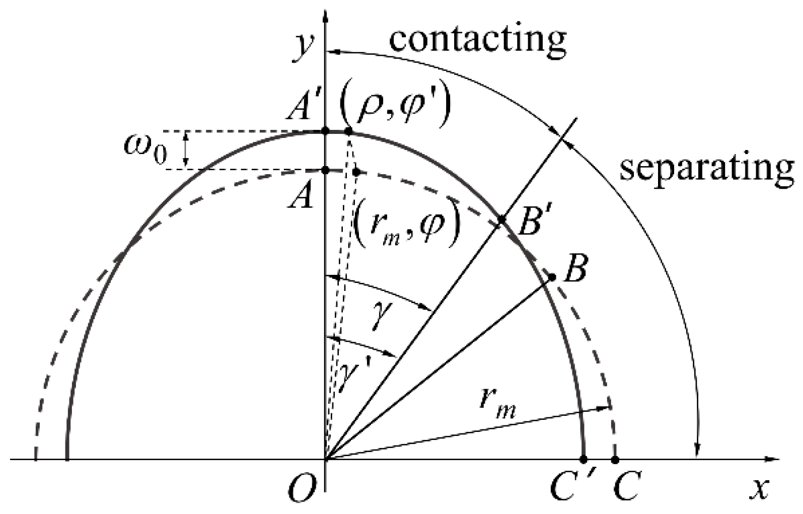
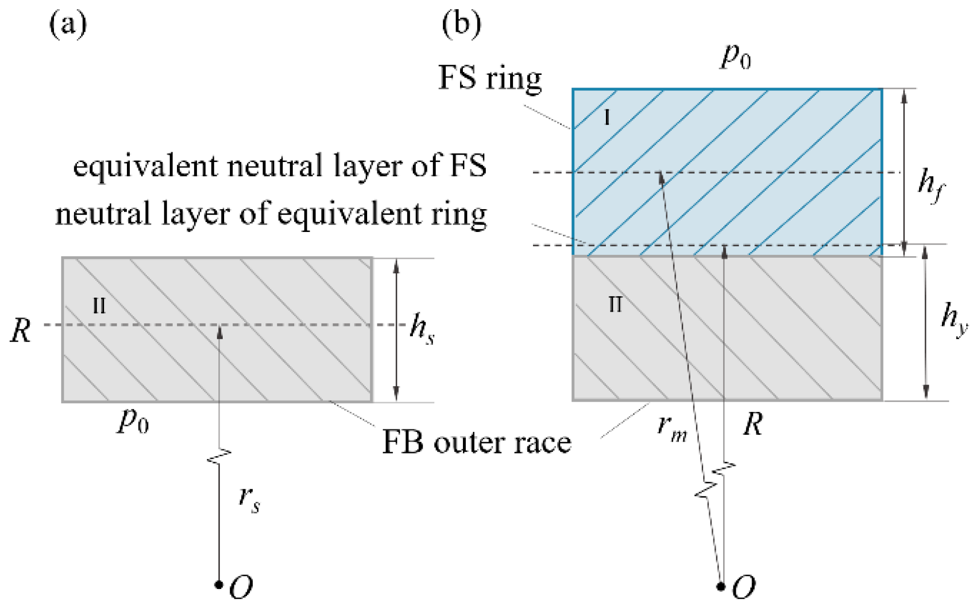
2.1. Improved Equivalent Ring

Based on the contact condition between the FS and FB, the equivalent ring is established. When the FS and FB are in contact, they are integrated as an entity. When no contact occurs, the equivalent ring is composed of the FB. The contact between the FB and FS after assembly is shown in Figure 2.
As shown in Figure 2, the FS is divided by wrapping angle γ into arc AB and arc BC before deformation. Arc AB is deformed to curve AB′ in close contact with the FB, and arc BC is deformed to curve BC′. Arc BC′ separates with the FS, when the WG is assembled with FS. γ′ is the wrapping angle after FS deformation. According to the geometric constraint and equilibrium equations of the ring with continuous conditions [25], γ′ can be calculated as follows:
0 γ ( ρ r m ) d φ + ρ ¨ | φ = γ 4 cos 2 γ + 2 γ π 2 cos γ sin γ π 2 γ 2 γ π + 2 cos γ sin γ + ρ ˙ | φ = γ cos 2 γ 2 π 4 γ 2 γ π + 2 cos γ sin γ + 3 + ρ ( γ ) r m π 2 γ = 0 ,
where the point at polar angle φ to the y-axis on the ring is moved to polar point (ρ, φ′) after FS deformed, rm is the FS neutral line radius. ρ is the polar diameter of the FS and can be calculated:
ρ = r a r b r a 2 sin φ 2 + r b 2 cos φ 2 .
In Equation (2), ra and rb are the major and minor axis of the ellipse, while ra is the sum of the FS neutral line radius rm and ω0 is the maximum radial deformation of the FS and FB outer race.
According to the assumption of non-elongation on the mid-layer, the relationship between γ′ and γ can be determined by the following equation:
r m γ = 0 γ ρ 2 + ρ ˙ 2 d φ ,
where γ′ can be determined by Equation (1), based on the numerical approximation method.
When the FS contacts the FB, it is represented as a ring without tooth features for computational simplicity, as illustrated in Figure 3. According to previous research [19], the tooth effect on the FS bending stiffness can be replaced by the FS bending stiffness coefficient Ctr. Ctr is mainly reflected in root thickness sf, dedendum arc radius rf, and tooth rack thickness h0. The characteristic formula of the Ctr can be fitted as shown in Equation (4):
C t r = 0.477 s f + 0.522 r f h 0 + 0.692 .
The bending strain energy of tooth unit and beam unit is identical after simplification. The bending stiffness of the ring EfIf can be calculated:
E f I f = C t r E 0 I 0 ,
where E0I0 is the bending stiffness of the beam with length p0, and E0 is the elastic modulus of the beam, and its section moment of inertia I0 can be calculated:
I 0 = b 0 h 0 3 12 ,
where b0 is the width of the beam, and h0 is its thickness.
Based on the simplified ring of the FS and its contact condition with the FB, an equivalent ring model is established, as depicted in Figure 4. The wrap angle γ′ is determined by Equation (1) under no or low external torque. According to Ivanov′s experiment [21], the wrapping angle is 90° in the first and third quadrants and 0° in the second and fourth quadrants when the FS is subjected to heavy external torque.
In Figure 4, Qi denotes the ball load of the ith ball and φi is the angular position of the ball. Sk denotes the meshing force of the kth tooth. θk is the angular position of the tooth, and αk is the meshing angle. The sum of moments generated by meshing forces relative to the center O is balanced with the external torque.
Referring to the cross section of the equivalent ring within a pitch as shown in Figure 5, the neutral line radius R of a point on the equivalent ring can be expressed in segments as follows:
(1)
If the point on the equivalent ring exceeds the range of the wrapping angle, then
R = r s ,
where rs is the neutral line radius of the FB outer race.
(2)
If the point on the equivalent ring does not exceed the range of the wrapping angle, then
R = h y + r s h s 2 ,
where hs is the thickness of the FB outer race.
The thicknesses of the FS and the FB outer race are too small for the radius R, so it can be assumed that the curvatures of the FS ring and the FB outer race are equal. Then, hy can be determined by the integral method,
h y = E s h s 2 + E f h f 2 h s + h f 2 E s h s + 2 E f h f ,
where Es is the elastic modulus of the outer race and hf is the equivalent thickness of the FS ring under the influence of the FS tooth, which can be calculated by the formula proposed by Yao [26].
The bending stiffness W of the equivalent ring is also segmented by the wrapping angle and is expressed as follows:
(1)
If the point on the equivalent ring exceeds the range of the wrapping angle, then
W = E s I s ,
where Is is the inertia moment of the outer race section.
(2)
If the point on the equivalent ring does not exceed the range of the wrapping angle, then
W = E s I s + E f I f .
Combining Equations (1) and (3) into Equation (11), the bending stiffness W can be written as:
W = E s I s + ( 0.477 s f + 0.522 r f h 0 + 0.692 ) E 0 I 0 .
Equation (12) can be used to reflect the influence of the FS’s geometric parameters on the bending stiffness W, which further affects the FB ball load.

2.2. Superposition Method for FB Ball Load

Due to the flexibility feature, the equivalent ring is deformed by the action of all unknown ball loads and meshing forces. The deformation coordination equation can be constructed using the superposition method:
δ i = C S S k sin α k + C Q [ Q i ] ,
where δi is the radial deformation on the equivalent ring at the angular position of the ith ball. CS and CQ are the influence coefficient matrixes consisting of unit radial deformations produced by meshing forces and ball load, and can be specifically expressed as:
C S = c S 11 c S 12 c S 1 z c S 21 c S 22 c S 2 z c S i k c S n 1 c S n 2 c S n z ,   C Q = c Q 11 c Q 12 c Q 1 n c Q 21 c Q 22 c Q 2 n c Q i j c Q n 1 c Q n 2 c Q n n ,
where n is the ball number and z is the FS tooth number.
Due to the thickness of the equivalent ring being too small for its radius, the change in the equivalent ring curvature is approximately equal when a force is applied on the point within or outside the wrapping angle. Thus, the deformation of the equivalent ring, which is segmented by the wrapping angle, still satisfies Thin-walled Ring Theory. The symbol cSik is used to represent the influence coefficient of the meshing force Sk on the equivalent ring at the angular position of the kth tooth, and it can be expressed in segments as follows:
c S i k = R 3 4 W ( θ k φ i ) sin ( θ k φ i ) + ( θ k φ i ) 2 π ( θ k φ i ) cos ( θ k φ i ) 2 , θ k φ i 0 R 3 4 W θ k φ i + 2 π sin ( θ k φ i ) + ( θ k φ i ) 2 θ k φ i + 2 π cos ( θ k φ i ) 2 , θ k φ i < 0 .
Similarly, cQij is used to represent the influence coefficient of the ball load Qj on the equivalent ring at the angular position of the ith ball, and cQij can be expressed in segments as follows:
c Q i j = R 3 4 W φ j φ i sin φ j φ i φ j φ i 2 π φ i j cos φ j φ i + 2 , φ j φ i 0 R 3 4 W φ j φ i + 2 π sin φ j φ i φ j φ i 2 2 cos φ j φ i + 2 , φ j φ i < 0 .
Equations (15) and (16) can be used to determine the influence coefficient matrixes in Equation (13). The meshing force Sk can be calculated iteratively using the meshing flexibility matrix, when the external torque of the HD is determined [27]. The ball load Qi can be expressed by Hertzian Contact Theory:
Q i = k u 3 / 2 ,
where k is the contact stiffness between the outer race and ball, u represents the contact deformation, which is the result of subtraction between the deformation δi and the initial radial clearance δi0. If the subtraction is less than zero, it means that the ball is not in contact with the equivalent ring, and u can be expressed as:
u = δ i δ i 0 , δ i δ i 0 0 , δ i < δ i 0 .
In Equation (18), δ i 0 = P d 2 + r m ρ . Where Pd denotes the internal radial clearance of the ball before the cam is inserted into an FB.
Combining Equation (18) into Equation (17), the ball load Qi in contact can be written as:
Q i = k δ i P d 2 + r m ρ 3 / 2 .
In summary, the radial deformation δi in Equation (13) is influenced by all ball loads, which are currently unknown. The relationship between the ith ball load Qi and the deformation δi can be established by Equation (19). A set of n nonlinear simultaneous equations can be constituted by substituting Equation (19) into Equation (13), and can be solved iteratively using the Newton–Raphson method. The flowchart for programming the computation of the ball load is shown in Figure 6.

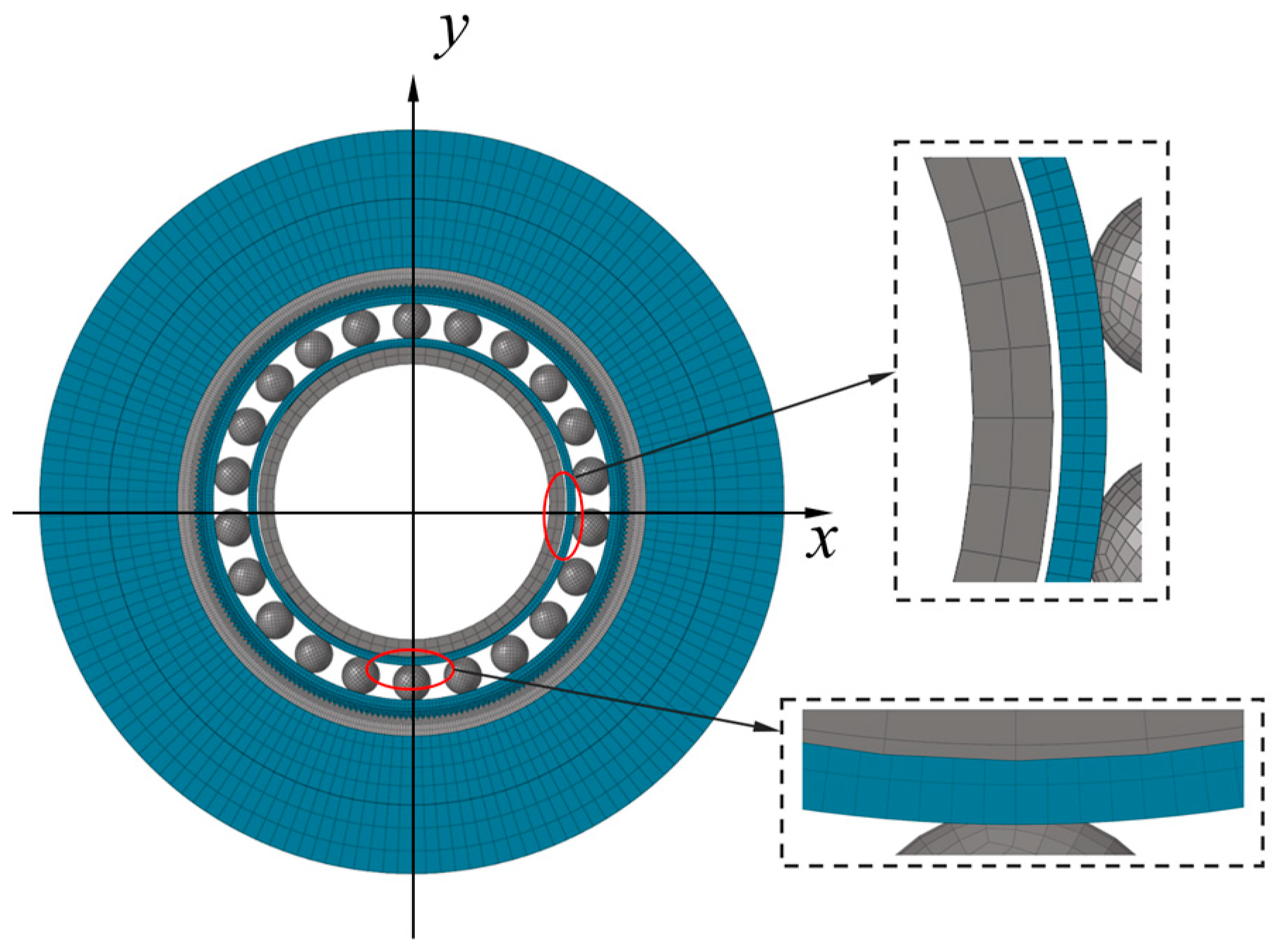
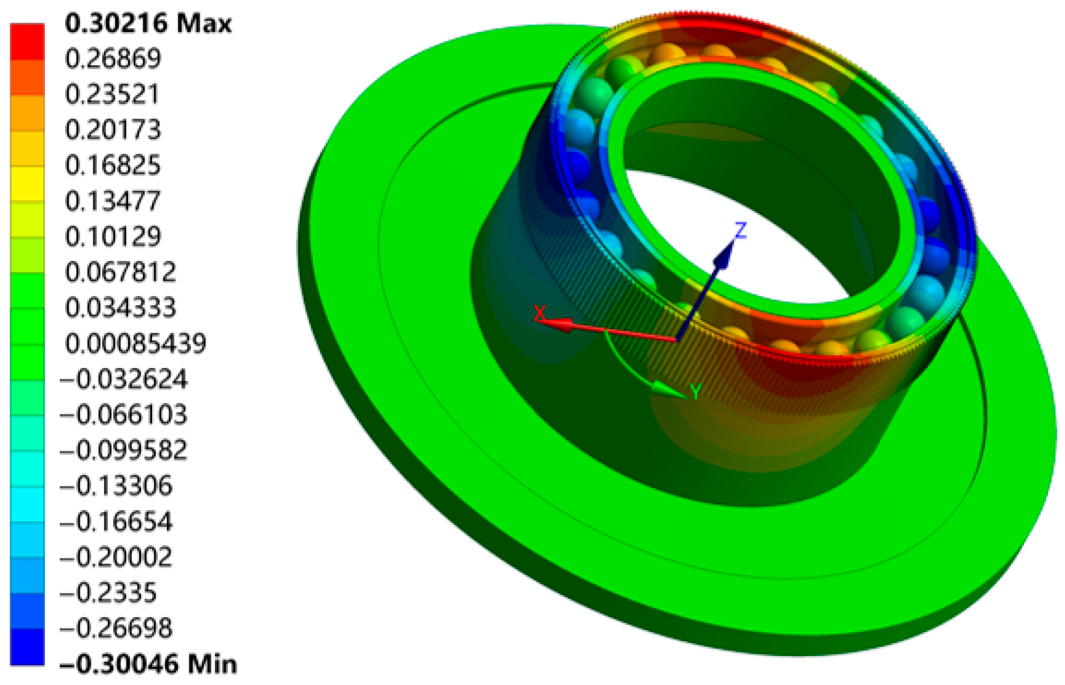
2.3. Validation of FB Ball Load

The simulation model of the HD (SHG-20-100) is built as shown in Figure 7, which refers to the geometric and material parameters in Table 1 and Table 2. The model is developed using a C3D8R element, a mesh number of 1,332,712, and a size of 0.25 mm. The element mass of the model is 0.97, its Jacobian ratio is 1.10, and its aspect ratio is 1.21. The model contact type is friction contact.
Simulation modeling of HD deformation and forces under loaded conditions in Ansys Workbench 2021 R2. The simulation consists of two steps. At the assembly stage, the gap between the FB and the FS is eliminated after the cam is inserted into the FB. Then, the external load T (14 Nm) is applied to the bottom of the FS at the loading stage. The radial deformation of the FS and the FB at the assembly stage is shown in Figure 8. The maximum radial deformation in the simulation is 0.302 mm, which occurs along the major axis. It is greater than the theoretical maximum radial deformation (ω0) of 0.72%. This shows that the simulation result of the deformation above matches the actual deformation, which confirms the reliability of the simulation model.
The variation of the FB ball load for the first ball at different angular positions is obtained using different calculation methods and is shown in Figure 9. According to the theoretical and simulation results, the number of balls in the contact state is the same. The maximum ball load occurs at the angular position of the first and twelfth balls according to all methods. The value of the maximum ball load in this study is 44.48 N, which is approximately 4.8% less than its simulation result (46.72 N). The maximum error of the ball load in this study is 6.09%, compared with 15.07% for the method proposed by Xiong [14]. These results show that the FB ball load calculated in this study is more consistent with the FEM, which indicates that the improved equivalent ring presented in Section 2.1 is more reliable.

3. Analyses of Influence on FB Ball Load

As described in Section 2, the FB ball load is relevant to the external torque and the geometric parameters of the FB and the FS, while the FB maximum radial deformation ω0 and the FS bending stiffness coefficient Ctr are selected to study their effects.

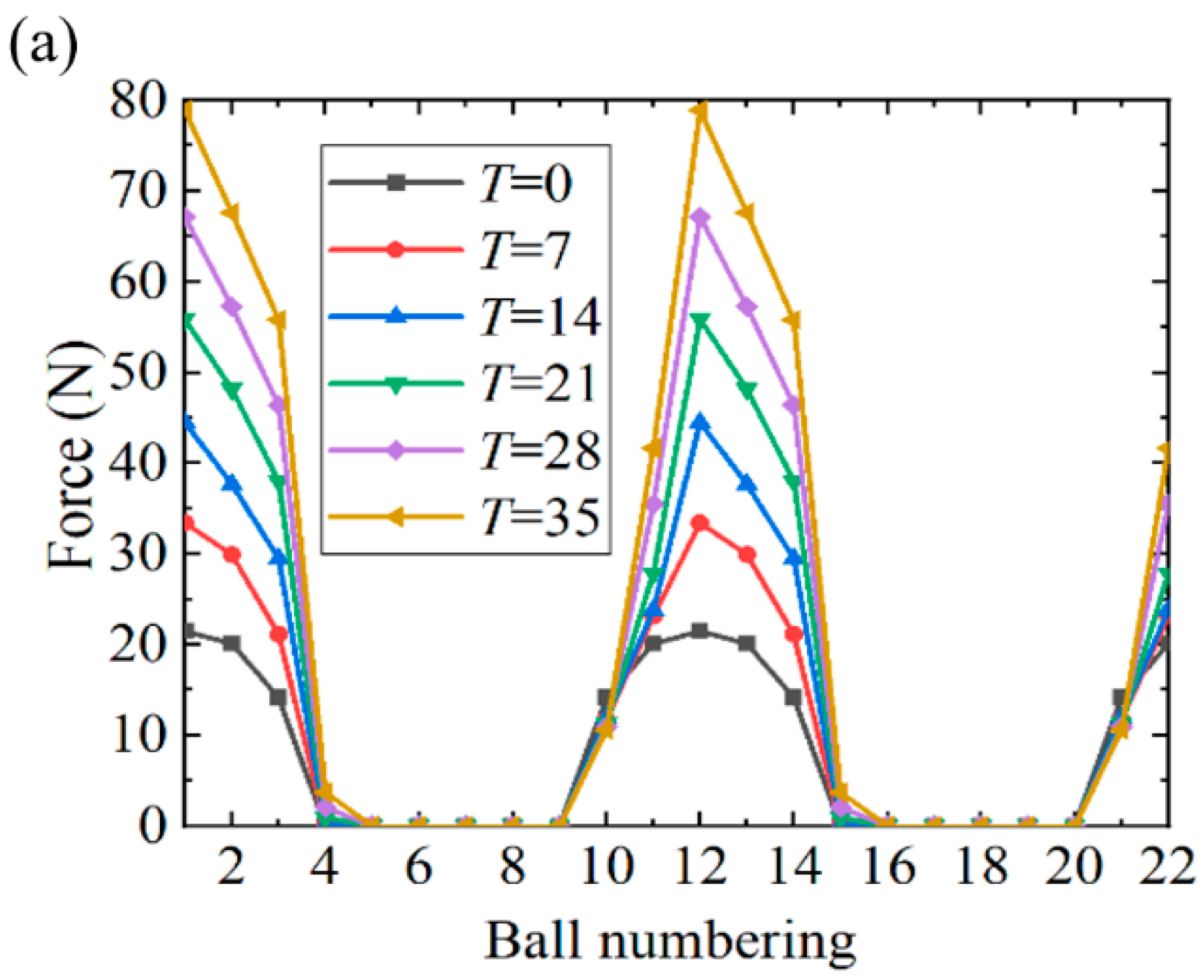
3.1. Influence of External Torque T

The rated torque of the HD (SHG-20-100) is 35 Nm. The external torque can be considered low when it is less than 30% of the rated load, while the heavy external torque exceeds 30% of the rated load. The FB ball load is calculated under various external torques (7 Nm, 14 Nm, 21 Nm, 28 Nm, and 35 Nm), as shown in Figure 10a. According to the results presented in the figure, the distribution of the FB ball load is no longer symmetrical with respect to the major axis due to the influence of the external torque, but is centrosymmetric. Therefore, only half of the balls engaged in contact (from the ninth to the fifteenth ball) are analyzed, as shown in Figure 10b. As the external torque T increases, the number of balls engaged in contact changes slightly, with 10 and 12 under low and heavy external torque, respectively. With the exception of the 10th ball, the FB ball load shows an increasing relationship with the external torque.

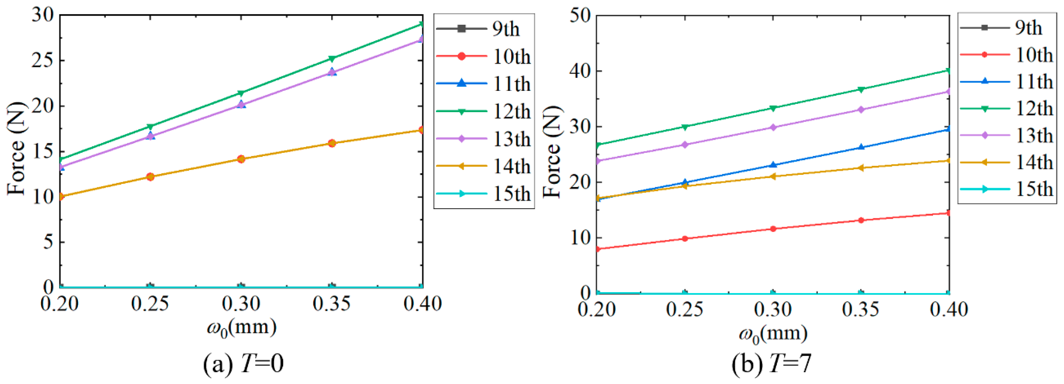
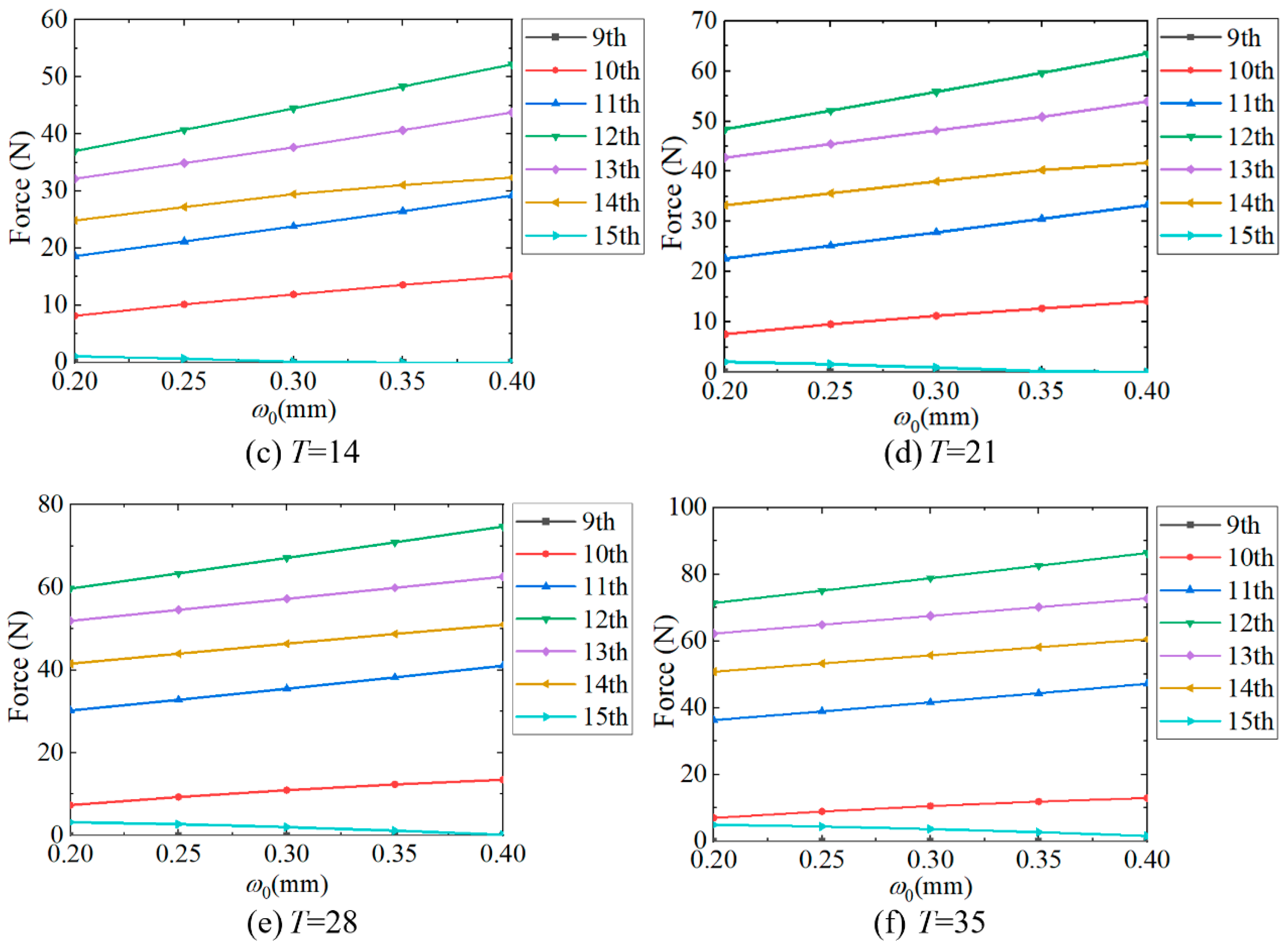
3.2. Influence of the Maximum Radial Deformation ω0

To analyze whether the influence of the maximum radial deformation ω0 on the ball load is affected by the external torque T, the FB ball load from the ninth to the fifteenth balls are calculated under various external torques. As shown in Figure 11, when the ω0 increases, the number of balls engaged in contact does not change under low external torque, but decreases under heavy external torque. As ω0 increases, the major contact ball loads (from the 10th to the 14th balls) show an approximately linear relationship with the ω0 under various external torque. The change rate of the major contact ball loads is calculated when ω0 increases from 0.2 mm to 0.4 mm, as shown in Figure 12. The result reveals that the ball loads exhibit higher sensitivity to ω0 under low torque, except for Ball 10, whereas the influence diminishes significantly near the rated torque. This demonstrates that external torque is critical when analyzing factors affecting the ball load. Consequently, prior studies concluding that ω0 dominates the ball load without external torque reveal significant limitations.

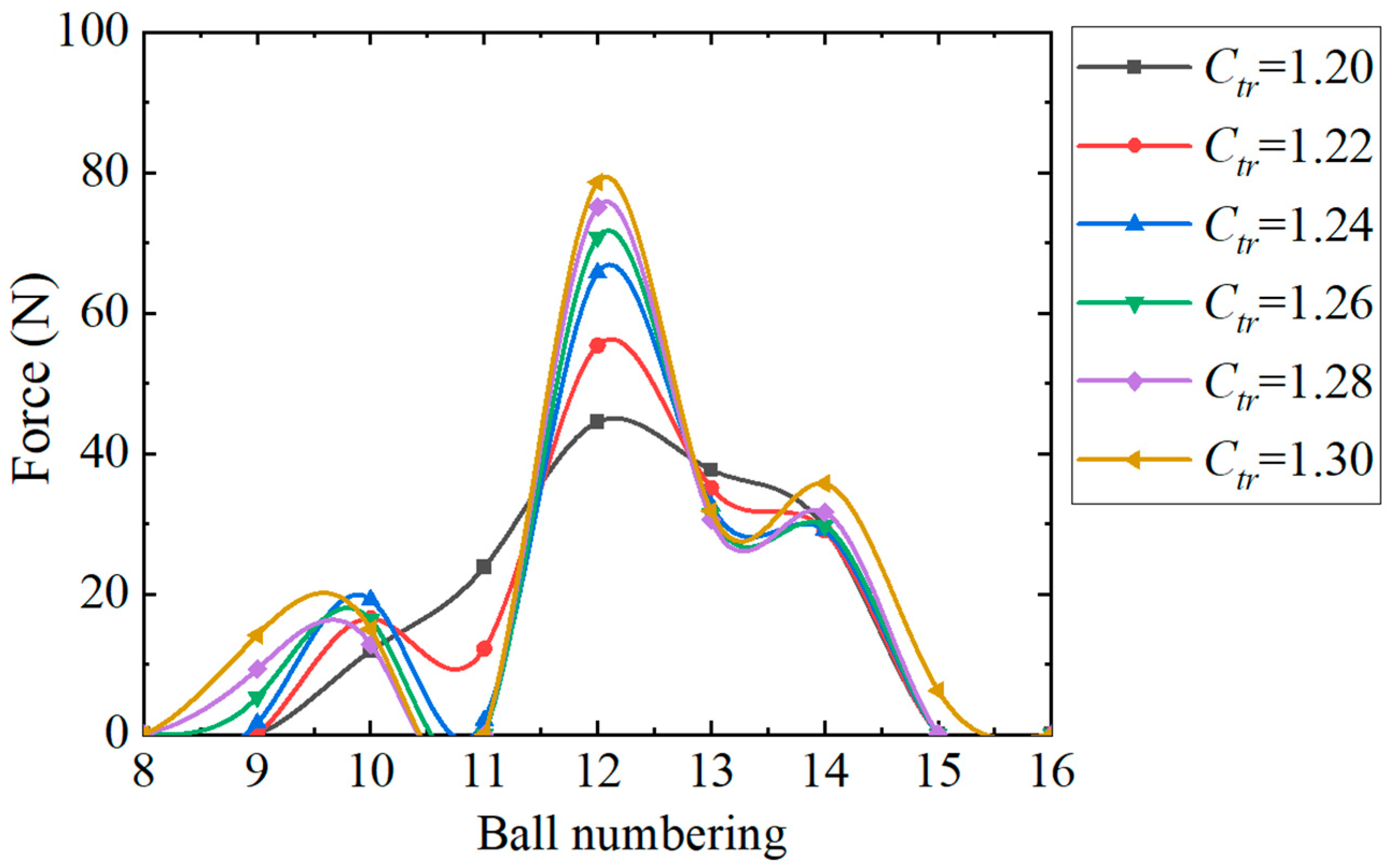
3.3. Influence of the FS Bending Stiffness Coefficient Ctr

Since the FS bending stiffness coefficient Ctr has an identified relationship with the root thickness sf, the dedendum arc radius rf, and the tooth rack thickness h0 in Equation (3), the influence of the FS tooth geometric parameter on the ball load can be replaced by Ctr. As can be seen in Figure 13, the geometric parameters of the FS tooth have an obvious effect on the ball load. When the bending stiffness coefficient Ctr increases from 1.2 to 1.3, the maximum ball load increases from 44.48 N to 78.61 N with a growth rate of 76.7%. It further proves that the influence of the FS tooth on the FB ball load cannot be ignored. When Ctr is greater than 1.24, three peaks appear in the distribution of the ball load. This may cause the FB to be subjected to more impacts, and its wear will be aggravated. However, the stress of the FS increases rapidly as Ctr decreases, which leads to fatigue failure of the FS [26]. Therefore, the minimum value of Ctr is suggested to be preferentially adopted when the maximum stress design requirement is met.
In order to analyze whether the influence of Ctr on the ball load is affected by the external torque T, the FB ball load from the ninth to the fifteenth balls are calculated under various external torques. As shown in Figure 14, the FS bending stiffness coefficient Ctr has little effect on the ball load under low external toque. However, the ball load reflects the complex non-linear change under heavy torque as Ctr varies. Therefore, the ball load is analyzed separately for low and heavy torque conditions.

4. Orthogonal Simulations and Fitting Formulae

Rapidly constructing the relationship between the FB ball load and the geometric parameters of the HD is of great significance for the study of wear. When the external torque is determined, the FB ball load is relevant to the maximum radial deformation of the FB ω0 and the bending stiffness coefficient Ctr. In this section, a variety of ball load distributions with different ω0 and Ctr are calculated, which are designed by orthogonal simulations. The formulas for solving the ball load in the major contact zone are fitted under low torque (7 Nm) and rated torque (35 Nm).

4.1. Orthogonal Simulation Under Low Torque

When the external torque T is 7 Nm, the results of the orthogonal simulation of the ω0 and Ctr of the FB ball load within the major contact zone are illustrated as a contour map in Figure 15. The ball load shows linear monotonic increasing trends with ω0 and Ctr. Then, a linear surface equation, as shown in Equation (20), is constructed to fit the FB ball load in Figure 15. The fitting results are illustrated in Table 3.
Q i = A 1 ω 0 + A 2 C t r + A 3 .
Obviously, the maximum ball load is directly proportional to both ω0 and Ctr under low torque. The maximum radial deformation ω0 has a more significant impact on the FB ball load than the bending stiffness coefficient Ctr. The effect of the FB wear on the clearance can be equated to a reduction in ω0, which means that when the HD is working under low torque, the coupled relationship between the FB wear and the FB ball load should be focused on. The variation of the FS geometric parameters on the ball load can be neglected, and the geometric parameters of the FB should be corrected for the investigation on wear.

4.2. Orthogonal Simulation Under Rated Torque

The results of the orthogonal simulation of the ω0 and Ctr of the FB ball load under rated torque are illustrated as a contour map in Figure 16. It can be noted that the ball load varies significantly with changing ω0 and Ctr.
Surface equations, as shown in Equations (21)–(25), are constructed to fit the FB ball load within the major contact zone in Figure 16. Based on Section 3, the 10th ball load is changed parabolically with Ctr. The surface equation can then be constructed:
Q 10 = 42.0258 ω 0 2491.4189 ( C t r + 0.02673 ω 0 1.2789 ) 2 + 9.7033 .
The 11th ball load is changed exponentially with Ctr. The surface equation can be constructed:
Q 11 = 35.4051 ω 0 + 9804.9620 e 3.7059 C t r 71.1757 .
The 12th ball load is changed in a power function with Ctr. The surface equation can then be constructed:
Q 12 = 250.8662 ω 0 1497.6177 C t r 0.0175 ω 0 12.8433 + 79.1926 .
The 13th ball load is changed parabolically with Ctr. The surface equation can then be constructed:
Q 13 = 15 . 2763 ω 0 + 861 . 1740 ( C t r 0 . 1423 ω 0 1 . 28073 ) 2 + 49 . 98569 .
The 14th ball load is changed in a power function with Ctr. The surface equation can then be constructed:
Q 14 = 47 . 17326 ω 0 + ( 0 . 16317 ω 0 + 0 . 76556 C t r ) 28 . 51751 + 41 . 38361 .
The relationship between the FB ball load and the geometric parameters of the FB and the FS can be rapidly established via Equations (21)–(25). Taking the maximum ball load as an example, combining Equation (3) and Equation (23), the maximum ball load can be written as:
Q 12 = 250.8662 ω 0 1497.6177 0.477 s f + 0.522 r f h 0 + 0.692 + 0.0175 ω 0 12.8433 + 79.1926
It can be seen in Equation (26) that, under rated torque, the geometric parameters of the FS are the main factors in the maximum ball load. When the FS is worn, the tooth rack thickness h0 is reduced. Then, the maximum ball load increases, which leads to severe wear on the FB and the FS. Therefore, in subsequent analyses of the FB wear, under rated external torque, the geometric parameter of the FS must be corrected.

5. Conclusions

Aiming to address the limitation of theoretical ball load calculations and their influence on factor analysis without external torque, an equivalent ring model is improved to calculate the FB ball load under various torques in this paper. The effects of the geometric parameters of the FB and the FS on the FB ball load are investigated. In addition, the fitting formulae are obtained to rapidly evaluate the FB ball load in a major contact zone. The conclusions are summarized as follows:
(1)
The ball load solution model is established under various external torques by analyzing the contact and deformation of the FS and the FB. The calculation of the FB ball load is more consistent with that of the FEM model. The maximum error of the ball load engaged in contact is 6.09%, and the accuracy was improved by 59.58% compared to the original equivalent ring model.
(2)
The FB ball load is greatly affected by the geometric parameters of the FS tooth. As the root thickness and the dedendum arc radius increase, the maximum ball load increases, and when the tooth rack thickness increases, the maximum ball load decreases. With the bending stiffness coefficient increasing from 1.2 to 1.3, the maximum ball load increases by 76.7%.
(3)
The geometric parameters that mainly affect the ball load vary under different external torques. The maximum radial deformation is the main factor under low external torque, while the bending stiffness coefficient is the main factor under rated external torque. This provides a basis for selecting the correction of the geometric parameters in subsequent wear analysis.

Author Contributions

N.Z. implemented the whole study and wrote the initial draft of the manuscript. J.W. contributed to the analysis and interpretation of the data and assisted with manuscript verification. M.W. and H.L. provided crucial comments on this work to improve its technical route. Y.T. designed the study and provided N.Z. with significant guidance om the analytical modelling method for flexible bearing load distortion. In short, all authors contributed to the study conception and design. All authors approved the final manuscript and were accountable for the study, ensuring that the data generated and analyzed are available. All authors have read and agreed to the published version of the manuscript.

Funding

This work is supported by the Fund of S&T Program of Hebei (23281805Z); S&T Program of Shijiazhuang Municipal (SJZZXC23002); National Key R&D Program of China (2022YFB4702100).

Data Availability Statement

Data are included in the article itself.

Conflicts of Interest

The authors declare no conflicts of interest.

References

  1. Song, C.; Li, X.; Zhu, C.; Du, X. Parametric analysis of tooth surface characteristics of flexspline in harmonic reducer after hobbing. Mech. Mach. Theory 2024, 194, 220–225. [Google Scholar] [CrossRef]
  2. Song, C.; Zhu, F.; Li, X.; Du, X. Three-dimensional conjugate tooth surface design and contact analysis of harmonic drive with double-circular-arc tooth profile. Chin. J. Mech. Eng. 2023, 36, 83. [Google Scholar] [CrossRef]
  3. Li, S. Diaphragm stress analysis and fatigue strength evaluation of the flex-spline, a very thin-walled spur gear used in the strain wave gearing. Mech. Mach. Theory 2016, 104, 1–16. [Google Scholar] [CrossRef]
  4. Dong, H.; Dong, B.; Zhang, C.; Wang, D. An equivalent mechanism model for kinematic accuracy analysis of harmonic drive. Mech. Mach. Theory 2022, 173, 104825. [Google Scholar] [CrossRef]
  5. Gamboa, J. Design and implementation of a pilot test for an industrial prototype of harmonic drive using a FPGA real-time system to implements control and instrumentation. Comput. Sci. 2009, 4, 297–303. [Google Scholar]
  6. Zhang, C.; Song, Z.; Liu, Z.; Cheng, Q.; Zhao, Y. Wear mechanism of flexspline materials regulated by novel amorphous/crystalline oxide form evolution at frictional interface. Tribol. Int. 2019, 135, 335–343. [Google Scholar] [CrossRef]
  7. Xing, J.; Yang, Z.; Ren, Y. Analysis of bifurcation and chaotic behavior for the flexspline of an electromagnetic harmonic drive system with movable teeth transmission. Appl. Math. Model. 2022, 112, 467–485. [Google Scholar] [CrossRef]
  8. Guida, R.; Bertolino, A.; De Martin, A.; Sorli, M. Comprehensive analysis of major fault-to-failure mechanisms in harmonic drives. Machines 2024, 12, 776. [Google Scholar] [CrossRef]
  9. Adams, C.; Skowronek, A.; Boes, J.; Melz, T. Vibrations of Elliptically Shaped Bearings in Strain Wave Gearing. J. Vib. Acoust. 2016, 138, 021004.1–021004.6. [Google Scholar] [CrossRef]
  10. Le, K.; Shen, Y. Load distribution on the wave generator of harmonic gear transmission. Mech. Sci. Technol. Aerosp. Eng. 1990, 34, 38–45. [Google Scholar]
  11. Shao, F.; Wen, S. Internal load analysis of flexible rolling bearings for harmonic gear transmission. Mach. Des. Manuf. 1991, 1, 34–37. [Google Scholar]
  12. Sumith, S.; Gupta, A. Design and parametric study of flexible ball bearings: A finite element approach. Mater. Today Proc. 2022, 56, 257–262. [Google Scholar] [CrossRef]
  13. Pan, X.; Dong, S.; Mu, S.; Zhao, X. Research on load distribution and fatigue life of flexible bearings in harmonic drive after assembly deformation. J. Mech. Strength 2020, 42, 453–458. [Google Scholar]
  14. Xiong, Y.; Zhu, Y.; Yan, K. Load analysis of flexible ball bearing in harmonic reducer. J. Mech. Des. 2019, 142, 1. [Google Scholar] [CrossRef]
  15. Zhao, B.; Liu, Z.; Song, C.; Tian, L. Mechanics analysis on flexible thin wall bearing in harmonic transmission. Bearing 2002, 10, 1–3. [Google Scholar]
  16. Li, X.; Song, C.; Zhu, C.; Song, H. Load analysis of thin-walled flexible bearing in harmonic reducer considering assembly with flexspline and cam. Mech. Mach. Theory 2023, 180, 105154. [Google Scholar] [CrossRef]
  17. Sahoo, V.; Maiti, R. Evidence of secondary tooth contact in harmonic drive, with involute toothed gear pair, through experimental and finite element analyses of stresses in flex-gear cup. Proc. Inst. Mech. Eng. Part C J. Mech. Eng. Sci. 2018, 232, 341–357. [Google Scholar] [CrossRef]
  18. Xin, H.; Mo, H.; Gao, J.; Wang, W.; Cui, D.; Liu, L.; Wang, T.; Xin, Y. Study on the gear tooth influence coefficients of flexspline of harmonic drive. Adv. Mater. Res. 2013, 774, 144–147. [Google Scholar] [CrossRef]
  19. Yao, Y.; Chen, X.; Xing, J. Tooth effects on assembling bending stress of flexible tooth rim in harmonic drive. Mech. Mach. Theory 2020, 150, 103971. [Google Scholar] [CrossRef]
  20. Trang, T.; Pham, T.; Hu, W. A quick stress calculation method for flexspline in harmonic actuators based on the finite element method. Cogent Eng. 2022, 9, 2138123. [Google Scholar] [CrossRef]
  21. Ivanov, M.N. Harmonic Drive Transmission; Shen, Y.; Li, K., Translators; National Defense Industry Press: Beijing, China, 1987. [Google Scholar]
  22. Dong, H.; Wang, D.; Ting, K. Kinematic effect of the compliant cup in harmonic drives. J. Mech. Des. 2011, 133, 051004. [Google Scholar] [CrossRef]
  23. Raja, M.; Iqbal, I.H.J.; Abidin, Z. Effect of bearing wear on linear and nonlinear responses of a rigid rotor supported by journal bearings. J. Mech. Sci. Technol. 2024, 38, 2741–2747. [Google Scholar] [CrossRef]
  24. Wu, M.; Han, X.; Tao, Y.; Pei, J. Lubrication reliability analysis of wind turbine main bearing in random wind field. Tribol. Int. 2022, 179, 108181. [Google Scholar] [CrossRef]
  25. Chen, X.; Liu, Y.; Xing, J. A novel method based on mechanical analysis for the stretch of the neutral line of the flexspline cup of a harmonic drive. Mech. Mach. Theory 2014, 76, 1–19. [Google Scholar] [CrossRef]
  26. Yao, Y.; Chen, X.; Xing, J. Tooth position and deformation of flexspline assembled with cam in harmonic drive based on force analysis. Chin. J. Mech. Eng. 2021, 34, 104. [Google Scholar] [CrossRef]
  27. Chen, X.; Yao, Y.; Xing, J. Meshing stiffness property and meshing status simulation of harmonic drive under transmission loading. Front. Mech. Eng. 2022, 17, 8. [Google Scholar] [CrossRef]
Figure 1. HD assembly diagram.
Machines 13 00627 g001
Figure 2. Schematic diagram of deformation analysis on FS.
Machines 13 00627 g002
Figure 3. Simplified schematic of FS.
Machines 13 00627 g003
Figure 4. (a) Equivalent ring model under no or low external torque, (b) Equivalent ring model under heavy external torque.
Machines 13 00627 g004
Figure 5. (a) The cross section of the equivalent ring in separate segments, (b) the cross section of the equivalent ring in contacting segment.
Machines 13 00627 g005
Figure 6. The flowchart for solving the FB ball load.
Machines 13 00627 g006
Figure 7. The mesh model of the HD.
Machines 13 00627 g007
Figure 8. Radial deformation of the FS and FB assembled on the cam.
Machines 13 00627 g008
Figure 9. The FB ball load with different solution methods (T = 14).
Machines 13 00627 g009
Figure 10. (a) Distribution of the FB ball load under various external torques and (b) the ball load for the 9th to the15th balls.
Machines 13 00627 g010aMachines 13 00627 g010b
Figure 11. FB ball load with different ω0 under various external torques.
Machines 13 00627 g011aMachines 13 00627 g011b
Figure 12. The change rate of the ball load with ω0 increasing from 0.2 mm to 0.4 mm.
Machines 13 00627 g012
Figure 13. FB ball load with different Ctr (T = 14).
Machines 13 00627 g013
Figure 14. FB ball load with different Ctr under various external torques.
Machines 13 00627 g014aMachines 13 00627 g014b
Figure 15. Contour map of the ball load under low external torque.
Machines 13 00627 g015
Figure 16. Contour map of the ball load under rated torque.
Machines 13 00627 g016
Table 1. Geometric parameters of HD.
ParameterDescriptionValueUnits
nNumber of balls22/
zNumber of FS teeth200/
rmFS neutral line radius24.450mm
rsneutral line radius of FB outer race18.850mm
hsthickness of FB outer race1.000mm
ω0The maximum radial deformation0.300mm
PdRadial clearance 0.001mm
sfroot thickness of FS tooth0.410mm
rfdedendum arc radius of FS tooth0.300mm
h0tooth rack thickness0.690mm
Table 2. Material parameters of HD.
PartMaterialElastic Modulus (MPa)Poisson’s Ratio
FS40CrNiMoA209,0000.295
FBGCr15219,0000.300
Cam42CrMo212,0000.280
Table 3. The parameters of the fitted surface.
The ith Ball Load QiA1A2A3
1033.96029.6640−10.2891
1165.450015.5663−15.1118
1270.073615.5621−6.2371
1365.236615.5269−8.1775
1434.95279.6516−1.2101
Disclaimer/Publisher’s Note: The statements, opinions and data contained in all publications are solely those of the individual author(s) and contributor(s) and not of MDPI and/or the editor(s). MDPI and/or the editor(s) disclaim responsibility for any injury to people or property resulting from any ideas, methods, instructions or products referred to in the content.

