Article

Multi-Physics and Multi-Objective Design of an Axial Flux Permanent Magnet-Assisted Synchronous Reluctance Motor for Use in Electric Vehicles

by
Emre Gözüaçık
* and
Mehmet Akar
Department of Electrical and Electronics Engineering, Faculty of Engineering and Architecture, Tokat Gaziosmanpasa University, 60150 Tokat, Turkey
*
Author to whom correspondence should be addressed.
Machines 2025, 13(7), 555; https://doi.org/10.3390/machines13070555
Submission received: 17 May 2025 / Revised: 21 June 2025 / Accepted: 24 June 2025 / Published: 26 June 2025
(This article belongs to the Section Electrical Machines and Drives)

Abstract

In this study, an axial flux double airgap permanent magnet-assisted synchronous reluctance motor (AF-Pma-SynRM) was designed for electric vehicles (EVs). The AF-Pma-SynRM model employs a forced liquid cooling method (cooling jacket) for a high current density. The model was tested using multi-objective optimization and multi-physics analysis. The AF-Pma-SynRM design has achieved 95.6 Nm of torque, 30 kW of power, and 93.8% efficiency at a 3000 rpm rated speed. The motor exhibits a maximum speed of 10,000 rpm, 253.1 Nm of torque, and 65 kW of output power. This study employs a novel barrier structure for axial motors characterized by fixed outer and inner dimensions, and is suitable for mass production. In the final stage, the motor was cooled using the cooling jacket method, and the average temperature of the winding was measured as 73.83 °C, and the average magnet temperature was 66.44 °C at a nominal power of 30 kW. Also to show variable speed performance, an efficiency map of the AF-Pma-SynRM is presented.

Graphical Abstract

1. Introduction

Axial flux machines are regarded as a significant competitor to radial flux machines within both the market and the extant literature. The short axial length of these machines provides advantages in terms of volume and weight. This fundamental difference in competition is a significant factor in terms of a high power density, high torque density, and high efficiency [1,2,3]. It has been demonstrated that the performance of axial flux machines can be enhanced by models with multiple air gaps to the extent permitted by the axial length.
The increasing number of problems such as energy crises, environmental pollution, and global warming is establishing electric machines in the market at a rapid rate [4]. It is imperative to reduce greenhouse gas emissions from internal combustion vehicles in order to prevent environmental hazards [3,5]. Despite ongoing efforts to reduce emissions, the deployment of EVs is regarded as the most promising approach to achieve zero emissions in the automotive sector. Electric motors are characterized by a wide Constant Power Speed Ratio (CPSR) and high performance, providing a significant advantage in the automotive industry by reducing losses, noise, and vibration [2,5]. The wide field weakening region achieved at high speeds, in accordance with CPSR, has a positive effect on the driving characteristics and the speed range at which constant power is provided [6,7].
In urban areas, consumers prefer EVs in the mini and small segments. The average speed of these vehicles is 34 km/h, with a maximum speed of 90 km/h. The power output of the vehicles in question is typically in the range of 33–54 kW [8]. The following data were obtained from the Toyota Prius: achieved peak power outputs of 33 kW (in 2003), 50 kW (in 2004), 60 kW (in 2010), and 53 kW (in 2017), with corresponding peak speeds of 5600 rpm, 6000 rpm, 13,500 rpm, and 17,000 rpm, respectively. Additionally, these motors have used different rotor barrier topologies, including flat-type, V-type, and double-layer U-type [4].
SynRM has a high fault tolerance due to its simple and robust structure, rendering it highly suitable for use in EVs. However, compared to permanent magnet motors, they have disadvantages, including a high torque ripple, vibration, and noise [9]. PMa-SynRM motors combine the durability and structural simplicity of SynRMs with the advantages of the high efficiency and power density of permanent magnet machines [10].
In the case of motors designed explicitly for EVs, it is imperative that two key performance criteria are met. Firstly, these motors must deliver a high torque at low speeds for acceleration and hill climbing. Secondly, they must provide constant power at high speeds, which is essential for highway driving [4,5]. In motors designed for EVs, rare-earth permanent magnets have been increasingly used to meet these requirements [4,11]. A study of electric car market data from 2015 to 2023 reveals that the Pma-SynRM and Permanent Magnet Synchronous Motor (PMSM) account for approximately 75% of the market [5]. The variable barrier structure of Pma-SynRM has been identified as a potential alternative to PMSMs. The Internal Permanent Magnet (IPM) motor is characterized by its high efficiency at average speeds, while the Pma-SynRM operates effectively at low torque and high speeds with reluctance torque [8,11,12].
In view of the exacting system requirements of EVs, optimization of the flux barrier geometry of Pma-SynRMs is imperative. To achieve high performance, multi-objective optimization and multi-physical analysis criteria should be considered in motor design [6,13,14,15]. For Pma-SynRM, the change in motor heat dissipation due to a high current under load will cause the demagnetization of the magnets and decrease the motor’s magnetic performance [16,17]. In this case, the mechanical configuration of the motor and the incorporation of cooling channels into the design will directly affect the motor’s thermal performance parameters.
This study investigates the methodology of designing AF-Pma-SynRM for EVs with multi-objective optimization and multi-physics analysis. This study prefers a double air gap structure, which is advantageous in terms of a high torque and power density in axial flux motors. The study also demonstrates that the double stator single rotor design is intended to increase the contact of the stator yoke and cooling channels in order to cool the stator windings, which are the primary source of heat [18]. Moreover, a novel innovation has been introduced to the existing literature about barrier design for the AF-Pma-SynRM model. The AF-Pma-SynRM flux barriers are narrowing from the outer diameter to the inner diameter due to the axial flux motor structure, thus giving rise to manufacturing difficulties. This study demonstrates that flux barriers do not undergo a volumetric change in either the outer or inner diameter. Consequently, an AF-Pma-SynRM design with flux barriers suitable for mass production has been realized.
The efficiency maps of traction motors used in EVs are among the basic parameters directly impacting battery system performance. In this context, the energy conversion efficiency of the motor under different speed and torque conditions is determined to ensure optimal energy management and system-level design processes [19]. This study involved preparing an efficiency map to determine the motor’s efficiency at different speeds and torque values.
This study presents the AF-Pma-SynRM design, which includes multi-objective optimization and multi-physics analysis stages. The first section explains the model design parameters and the original rotor and barrier structure. The second chapter shows the results of the multi-objective optimization study of the motor. It also determines the constant-torque/power regions of the final model and creates an efficiency map. The third chapter explains the results of the mechanical analysis of the motor. The final chapter compares the results of thermal analyses performed at different powers and different flow rates.

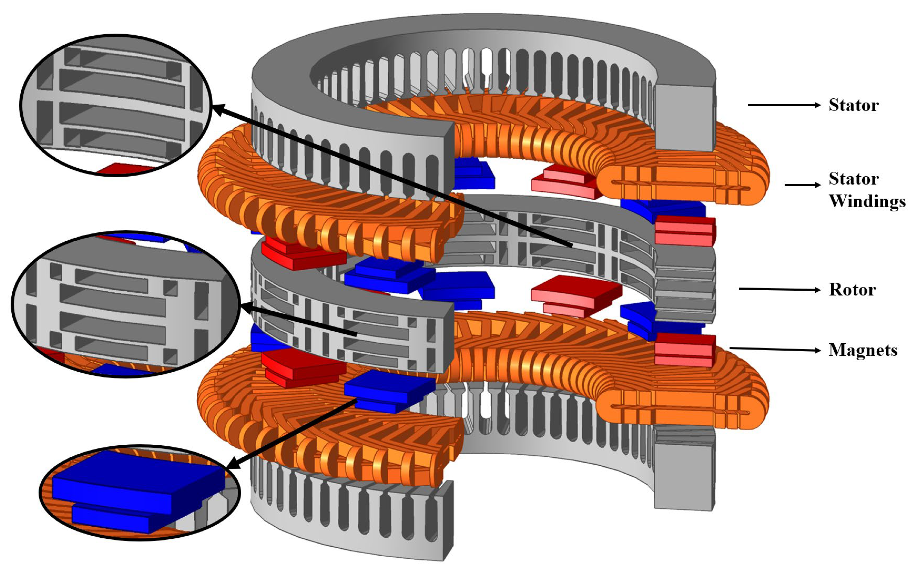
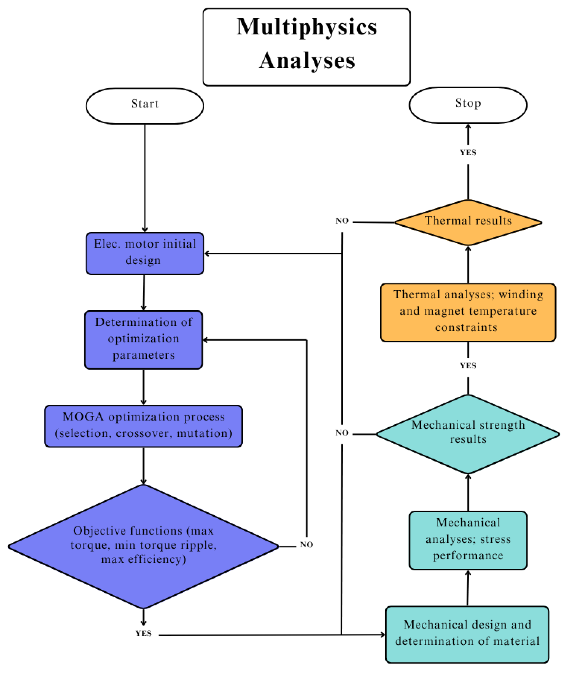
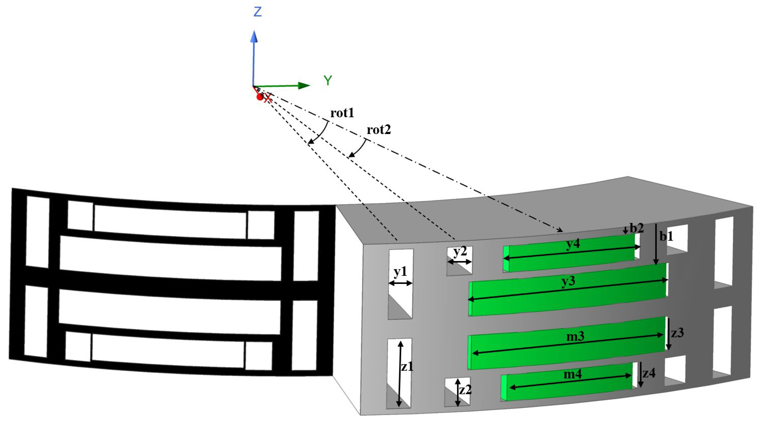
2. Materials and Methods

This study involved developing a design for an AF-PMa-SynRM for use in EVs. The basis for this was a small-segment vehicle prototype intended for urban use. A nominal power calculation was performed to analyze the forces acting on the vehicle. Considering the acceleration requirements during operation, the required motor speed for a maximum speed of 130 km/h was determined.
F d = m a A c c . F o r c e + m g sin α H i l l   C l m b i n g R e s i s t .   F o r c e + f r c m g cos α R o l l i n g   R e s i s t . F o r c e + 0.5 ρ C d A v f ( V + V m ) 2 A e r o d y n a m i c s   D r a g   F o r c e
Equation (1) calculates the total force Fd acting on the vehicle based on the acceleration force, hill-climbing resistance force, rolling resistance force, and aerodynamic drag force. Equation (1) uses the following variables: m for vehicle mass; a for vehicle acceleration; g for gravitational acceleration; α for road incline angle; Frc for rolling resistance coefficient; ρ for air density; Cd for aerodynamic drag coefficient; Avf for vehicle front surface area; V for vehicle speed; and Vm for wind speed.
Based on the calculations for initial acceleration, hill climbing, and high-speed highway driving, the electric motor was designed to operate at a nominal power of 30 kW and a nominal speed of 3000 rpm, with a maximum speed of 10,000 rpm [20].
Figure 1 shows a flowchart illustrating the initial design process for the AF-PMa-SynRM. The design process begins with determining vehicle parameters and calculating the traction power. Target torque, power, and speed values are defined at this stage. After the initial design parameters have been determined, the motor is sized using mathematical methods. In radial flux machines, the motor power is proportional to the square of the outer diameter and stack length. In axial flux machines, however, the power is proportional to the cube of the motor’s outer diameter [20].
Based on the forced liquid-cooled structure, the current density was sized to 10–30 A/mm2 [21]. Based on the selected current density, the phase current, the conductor cross-section, and the number of conductors are calculated. The magnetic flux distribution is analyzed to determine the core dimensions, including the stator tooth width, stator yoke, and rotor flux path thicknesses. The configuration of the rotor barriers, including their number, position, and geometry, was determined. Subsequent to this determination, electromagnetic analyses were conducted utilizing the finite element method (FEM). Revisions to the design parameters were made based on the obtained motor performance.
The AF-Pma-SynRM is an axial flux motor design featuring a middle rotor and double air gap, intended for use in EVs. The design parameters and performance values are given in Table 1. The AF-Pma-SynRM model has a 10-pole, 60-slot stator design, a 2-barrier magnet-assisted rotor structure, and a total axial length of 102 mm. The calculated values of the rated speed, torque, and power are based on the requirements of a small segment vehicle and the relevant driving cycles for EVs.
The AF-Pma-SynRM 3D model is illustrated in Figure 2. The AF model with a double air gap (double stator/middle rotor) has been designed in accordance with the NS torus topology [19]. N42SH rare-earth magnets have been placed in horizontal barriers.
One of the most significant disadvantages inherent in the axial flux model design is narrowing the axial structure from the outer diameter to the inner diameter. The AF-Pma-SynRM and AF-IPM designs necessitate narrowing the barriers and magnets inward [22,23]. Due to its variable dimensions, this conical design poses problems in the manufacturing phase.
The barrier design of the AF-Pma-SynRM model shown in Figure 2 is suitable for mass production. Despite the conical structure, the outer and inner dimensions of the barriers and magnets remain constant. These variations in the outer and inner diameters are compensated for by the narrowing of the core between the barriers, as is the narrowing of the stator teeth. In structural design, maintaining consistent barrier dimensions from the outer to the inner diameters reduces the core volume in the inner diameter region. However, the magnetic flux distribution in the outer diameter region remains acceptable, and the outer diameter volume is used effectively. Although the reduction in core volume at the inner diameter and the proximity of the barriers due to the conical structure cause local increases in flux density, these have no significant negative impacts on performance and are negligible when considering barrier geometries suitable for mass production. In this model, barrier molds are formed as in the stator slots. Using these molds facilitates the manufacture of the rotor by the punch method.
AF-Pma-SynRM rotor barrier molds can be processed into laminated steel sheets suitable for mass production. The problem of manufacturing the standard AF machine rotor barrier structure, which has variable dimensions ranging from the outside to the inside diameters, cannot be solved with a single mold.
This study involved performing electromagnetic analyses using ANSYS 2025R1 software based on a 3D AF-PMa-SynRM model. To optimize the calculation time, a 1/10 3D model was used. The TAU mesh method was employed for the analyses, and the total number of mesh elements was 145,891. The transient analysis time was set to 0.008 s, and the time step to 0.000133 s. All analyses were performed on a computer system equipped with an AMD Ryzen 9 7950X 4.50 GHz processor and 64 GB of RAM.
Motors designed for EVs require an initial design, optimization, stress analysis, thermal analysis, efficiency mapping, and determination of the motor’s characteristics as a function of the driving cycle [15,24,25]. Figure 3 shows a multi-physics flowchart describing the design, optimization, stress analysis, and thermal analysis steps of the AF-Pma-SynRM model. In this study, the workflow was defined according to these steps.

3. Results and Discussions

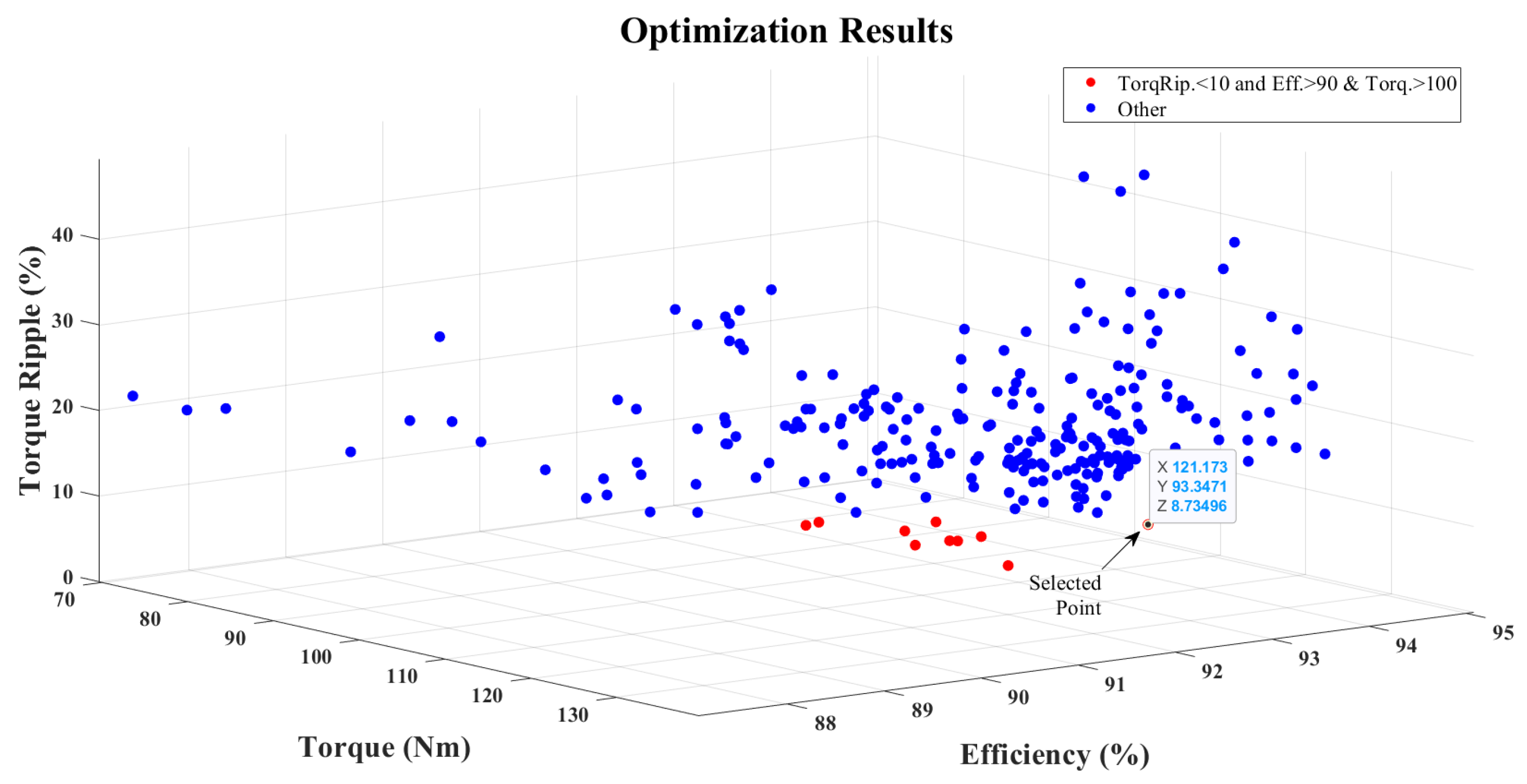
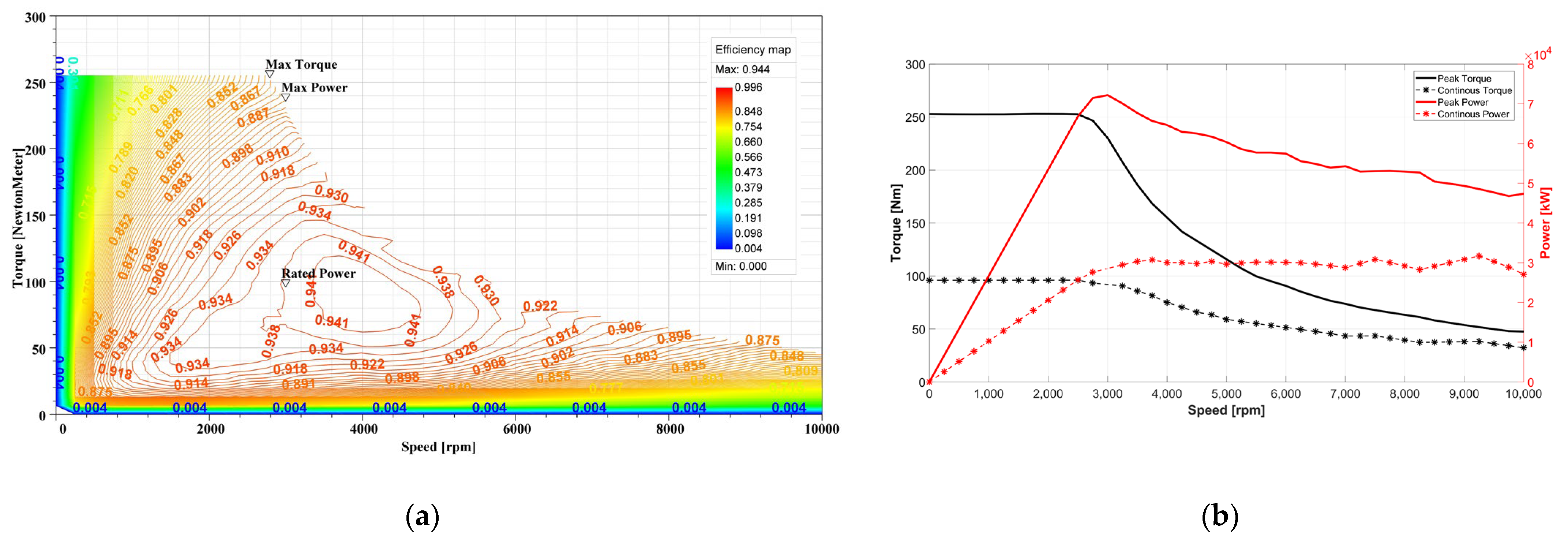
3.1. Optimization of AF-Pma-SynRM

The fundamental characteristic of SynRM is to create a flux path through the barriers added in the rotor section and to generate torque from the reluctance/inductance difference in the d-q axes. The rotor barrier structure determines the saliency ratio, which is the ratio of the rotor d-axis inductance to the q-axis inductance. The saliency ratio has a direct effect on motor performance [22]. For this reason, optimizing the rotor design parameters allows us to achieve the best model. For Pma-SynRM, reducing torque ripple and increasing torque and efficiency can be considered the main performance criteria [26,27]. The Genetic Algorithm (GA), developed based on biological gene transfer, can be used for optimization studies. GA employs an optimization structure that is based on randomly generating new individuals and selecting the most suitable individuals according to the objective function through selection, crossover, mutation, and replacement operations. Multi-Objective Genetic Algorithms (MOGAs) are used in systems with more than one objective function [22,24,26].
In this study, the AF-Pma-SynRM model for EVs requires a high torque, power, and efficiency, depending on the driving cycle conditions. Since torque ripple causes noise and vibration, the aim is to reduce it to a minimum. In this case, rotor barrier design parameters are used for multiple objective functions to optimize torque, torque ripple, and efficiency with MOGAs [26].
O b j F u n c = 0.2 [ T a v g T max ] 2 + 0.6 [ T r i p T r i p 0 ] 2 + 0.2 [ η a v g η max ] 2
Equation (2) reduces the objective function to a single function depending on the torque, torque ripple, and efficiency. SynRMs experience significant torque ripples due to their reluctance-based rotor structures [10]. In the initial design of the AF-PMa-SynRM, 120.9 Nm of torque, a torque ripple of 23.5%, and an efficiency of 92.8% were achieved. In the optimization study, the maximum torque (Tmax) was found to be 125 Nm for a 106 Arms phase current. Similarly, in the optimization studies where the objective function is minimum torque ripple or maximum efficiency, the best results were obtained with Trip0 = 6% and ηmax = 95%. While the torque ripple was more pronounced in the initial model, the torque and efficiency values were more stable and well-balanced. Similar to the study conducted by Gedera [27], the objective function in Equation (2) is formed to approach these optimum values, with weights of 20% for torque and efficiency, and 60% for torque ripple [27].
Figure 4 shows the AF-Pma-SynRM 1/10 model rotor and the variable parameters. By varying these parameters within certain limits, the aim is to bring the value of the objective function closer to zero. y1, y2, y3, and y4 are the widths of the rotor barriers and m3 and m4 are the widths of the magnets. b1 and b2 are the distances between the magnets and the air gap. z1 and z2 are the lengths of the vertical barriers, and z3 and z4 are the lengths of the horizontal barriers. To increase the mechanical strength in the rotor design, the rib/iron bridge section between the air gap and the barriers is fixed at 1 mm. In this case, z1 and z2 were not added to the optimization and were kept constant with the equations z1 = b1 + z3 + 1 mm and z2 = b2 + z4 + 1 mm. ‘rot1’ and ‘rot2’ are the angles that define the position of the vertical barriers with respect to the center of the pole.
Table 2 shows the variables of the barrier parameters, their limits, and the optimized parameter values. To avoid structural disturbances during optimization, the rotor parameters were analyzed in the maximum and minimum value ranges to prevent intersecting and interfering with the barrier structures.
The optimization results of the AF-Pma-SynRM model are shown in Figure 5. The graph highlights the values where the torque ripple is less than 10%, and torque and efficiency are greater than 100 Nm and 90%, respectively. The optimization results show that the final AF-Pma-SynRM model achieves 121.17 Nm of torque, 8.73% of torque ripple, and 93.34% efficiency at 106 Arms and a 13.22 A/mm2 current density.
The efficiency map results of the final AF-Pma-SynRM model are shown in Figure 6a. At a 3000 rpm rated speed, 30 kW of power, 95.6 Nm of torque, and 93.8% efficiency were obtained. It operates at maximum efficiency up to 94.4% in the 3000–5000 rpm range. Figure 6b shows the speed–torque and speed–power curves. The AF-Pma-SynRM has been determined based on the maximum and nominal torque/power values for the constant power and constant torque regions [6]. A maximum constant torque of 253.1 Nm is obtained at low speeds, and a maximum power of 74 kW at a rated speed. The AF-PMa-SynRM motor produces a nominal torque of 95.6 Nm at a nominal speed of 3000 rpm within the constant torque range and maintains a nominal power performance of 30 kW at high speeds. In the 3000–10,000 rpm speed range, there is a minimum constant power of 45 kW in the continuous power range. The CPSR value of the designed AF-Pma-SynRM model is greater than 3.3 due to the width of the field weakening region at high speeds and obtains constant power greater than the nominal power at peak speed.

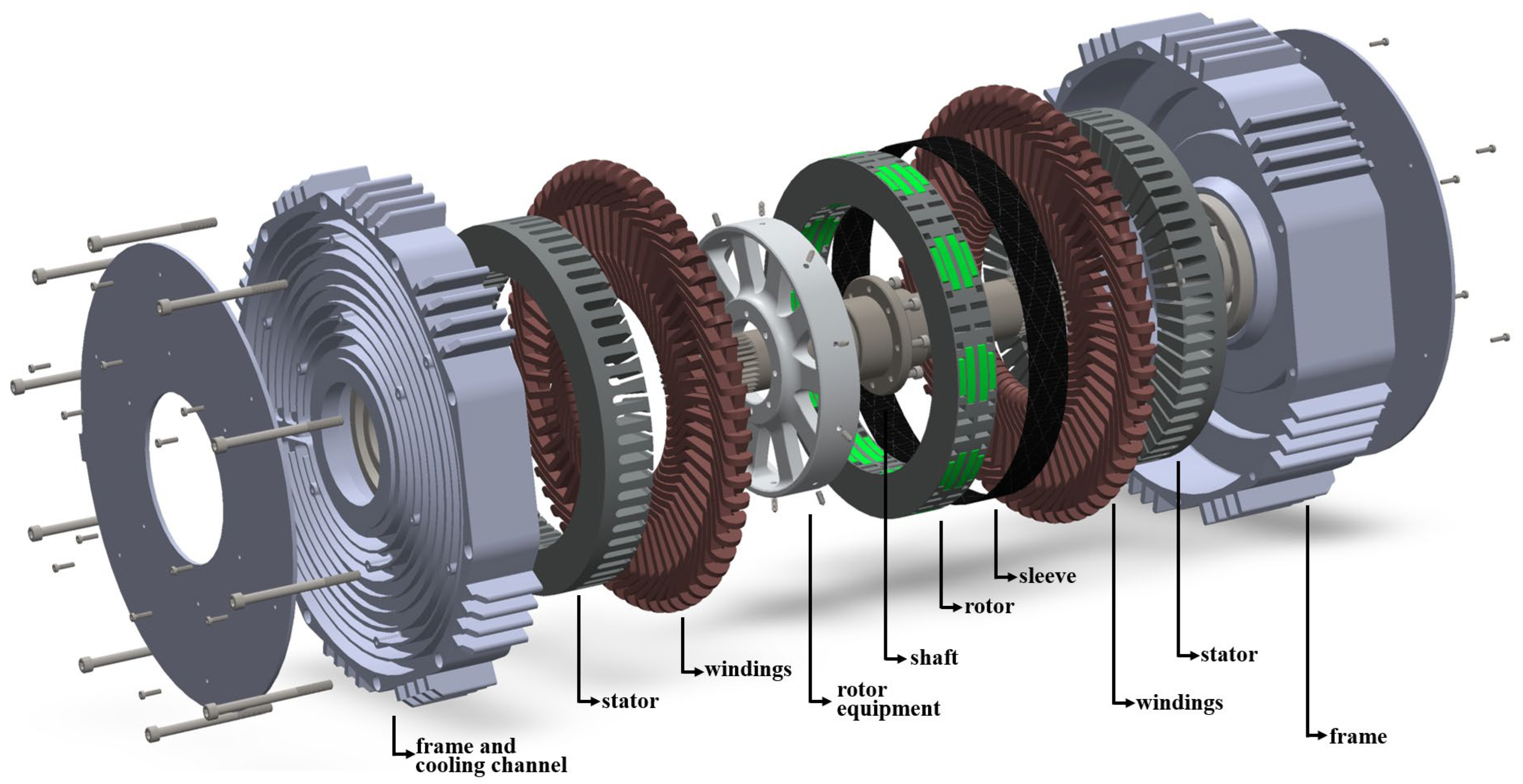
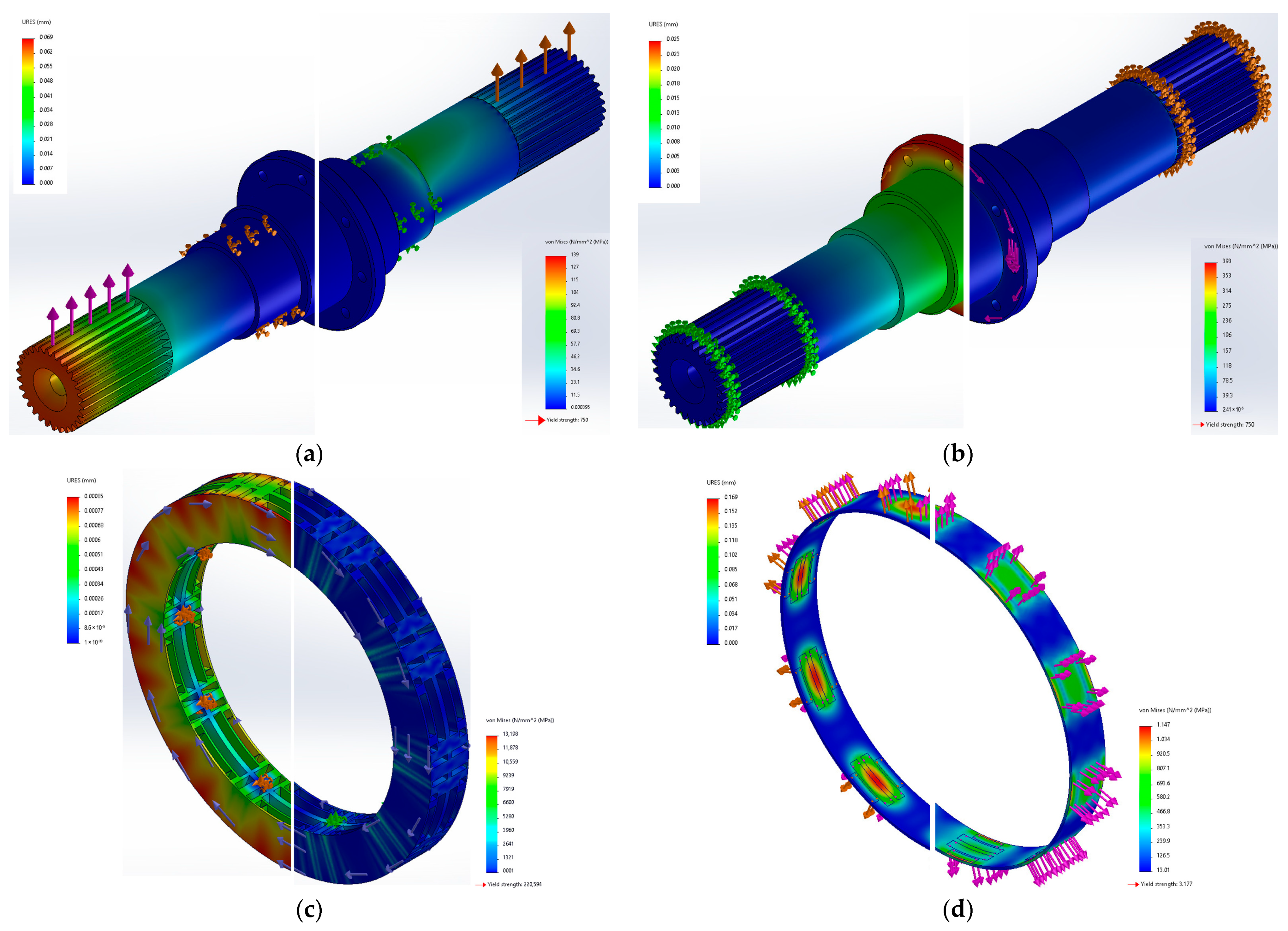
3.2. Mechanical Design and Stress Analyses of the AF-Pma-SynRM Model

The AF-Pma-SynRM model determined a peak torque of 253 Nm, a peak power of 74 kW, a peak speed of 10,000 rpm, and a peak current density of 30.84 A/mm2. Magnetic and mechanical losses are a significant heat source in high-current-density electric motors. This increases the cooling requirements of the motors to compensate for the heat dissipation. For electric motors with a current density of 10–30 A/mm2, forced liquid cooling is recommended [21].
The appearance of the AF-Pma-SynRM model, designed with high electromagnetic performance, thermal concerns, and EV requirements, is shown in Figure 7. The model uses 42CrMo4 steel for the shaft, which transmits the motor’s power to withstand high loads. The stator and rotor are made of laminated steel (JFE 35JN230), while the connecting part to the rotor and the motor frames are made of Al6061 aluminum for thermal conductivity and lightness [28]. The rotor equipment is fixed to the rotor using 3 mm × 12 mm set screws. Steel screws are used to minimize distortion in the magnetic flux path.
Stress analyses were performed after the completion of the mechanical drawings. In Figure 8, the stress analyses of the AF-Pma-SynRM model are shown separately as stress and displacement. As the motor is designed for EVs, the bending stress analysis of the shaft was performed under the assumption that the full load is applied directly to the shaft. The torsional stress analysis results of the shaft and rotor are shown for high torque locking situations.
In Figure 8a, the motor shaft (42CrMo4 hardened steel) has a yield strength of 750 MPa [28]. For the bending stress analysis, the effects of the EV weight, passenger weight, etc., on the motor shaft were measured with a load of approximately 11 kN in the event of failure. In this situation, there is a maximum stress of 138 MPa on the shaft, and the maximum displacement due to this stress is 0.06 mm. The safety factor can be calculated by dividing the yield strength by the maximum stress value [24]. It is 5.44 times more reliable, depending on the yield strength.
s f = 0.58 x ( y i e l d   s t r e n g t h ) max   t o r s i o n   s t r e n g h t h
Figure 8b analyzes the effect of 25% more than the maximum motor torque (~316 Nm) on the shaft. The maximum torsional stress is 101 MPa, and the maximum displacement is 0.02 mm. Equation (3) gives the safety factor formula based on the torsional stress analysis of the mechanical part [28]. According to this, the shaft is 4.31 times more reliable regarding torsional stress.
In Figure 8c, stress analyses of the rotor, which is the part of the AF-Pma-SynRM model to be structurally investigated with its barrier structure, have been carried out. The rotor is made of laminated steel material with a yield strength of 220.6 MPa. When similarly locked to the motor shaft, a maximum stress of 13.2 MPa occurs on the rotor mounting bolts. However, the maximum displacement is 0.0008 mm in the rib/iron bridge area close to the rotor air gap. The safety factor of the rotor is calculated to be 9.67, as given in Equation (3).
In the AF-Pma-SynRM motor design, a 2 mm-thick carbon fiber reinforced plastic (CFRP) sleeve has been added around the rotor. This is to prevent the dislodgement of the magnets due to centrifugal force at a maximum speed of 10,000 rpm. The CFRP sleeve (T300 type) possesses a tensile strength of 3530 MPa and an elastic modulus of 230 GPa [29]. At maximum speed, the centrifugal forces acting on magnet 1 (bottom barrier—0.0517 kg) and magnet 2 (top barrier—0.02576 kg) were calculated to be approximately 6006.67 N and 2989.8 N, respectively. As shown in Figure 8d, a structural analysis of the rotor sleeve was conducted without any adhesive bonding, frictional resistance, or magnetic attraction between the rotor core and the magnets. This analysis found that the safety factor for the rotor sleeve was 2.77, and the maximum displacement was 0.169 mm.

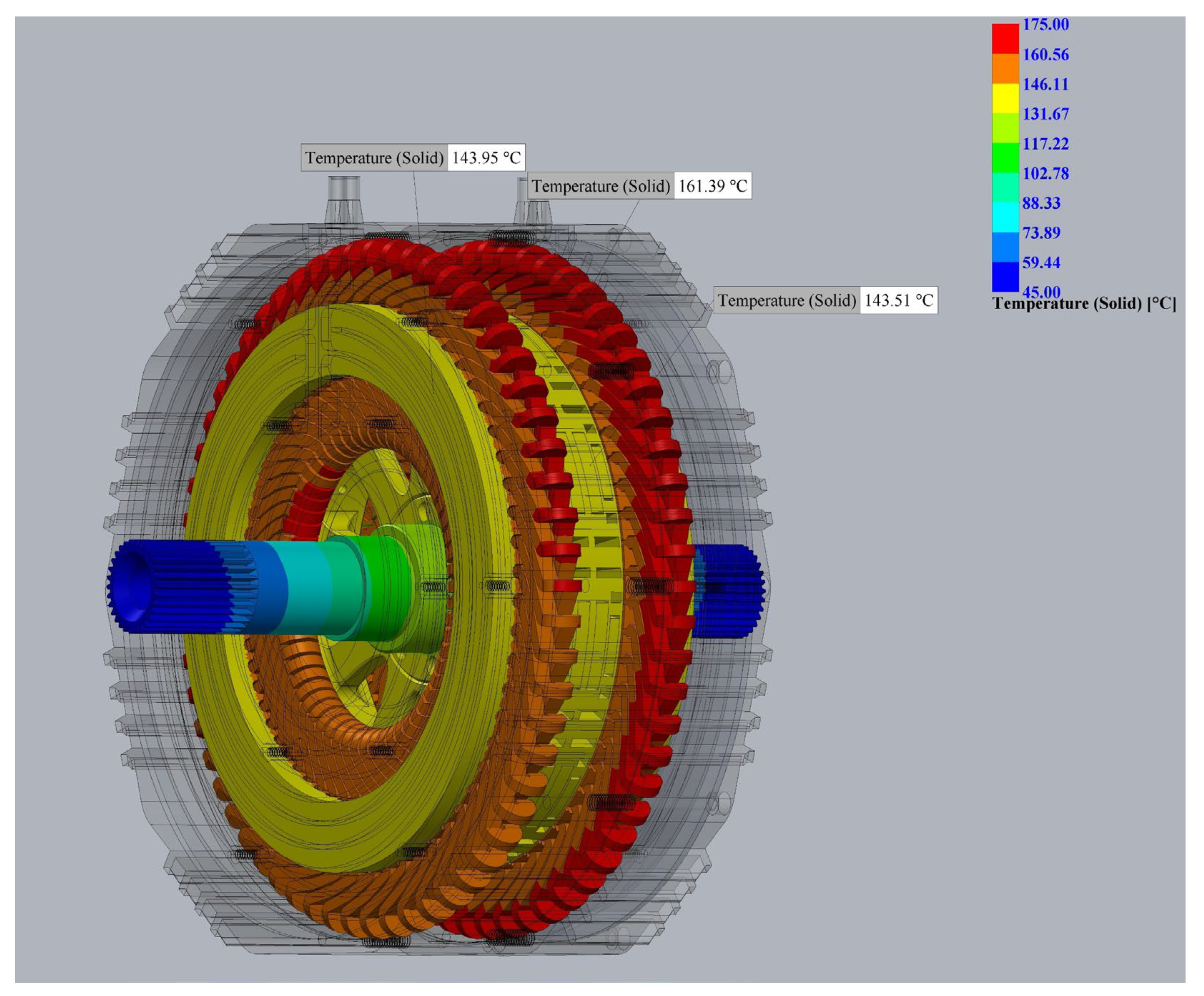
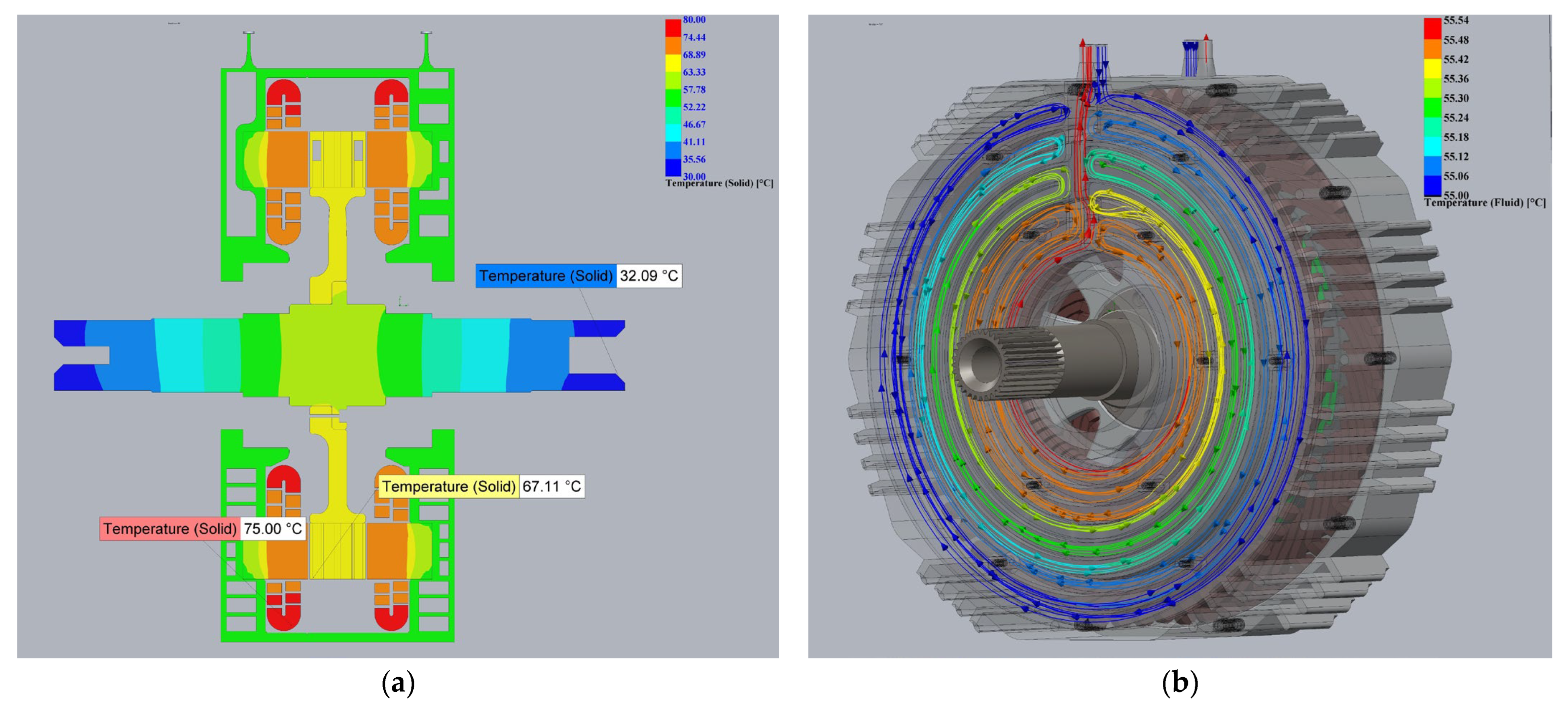
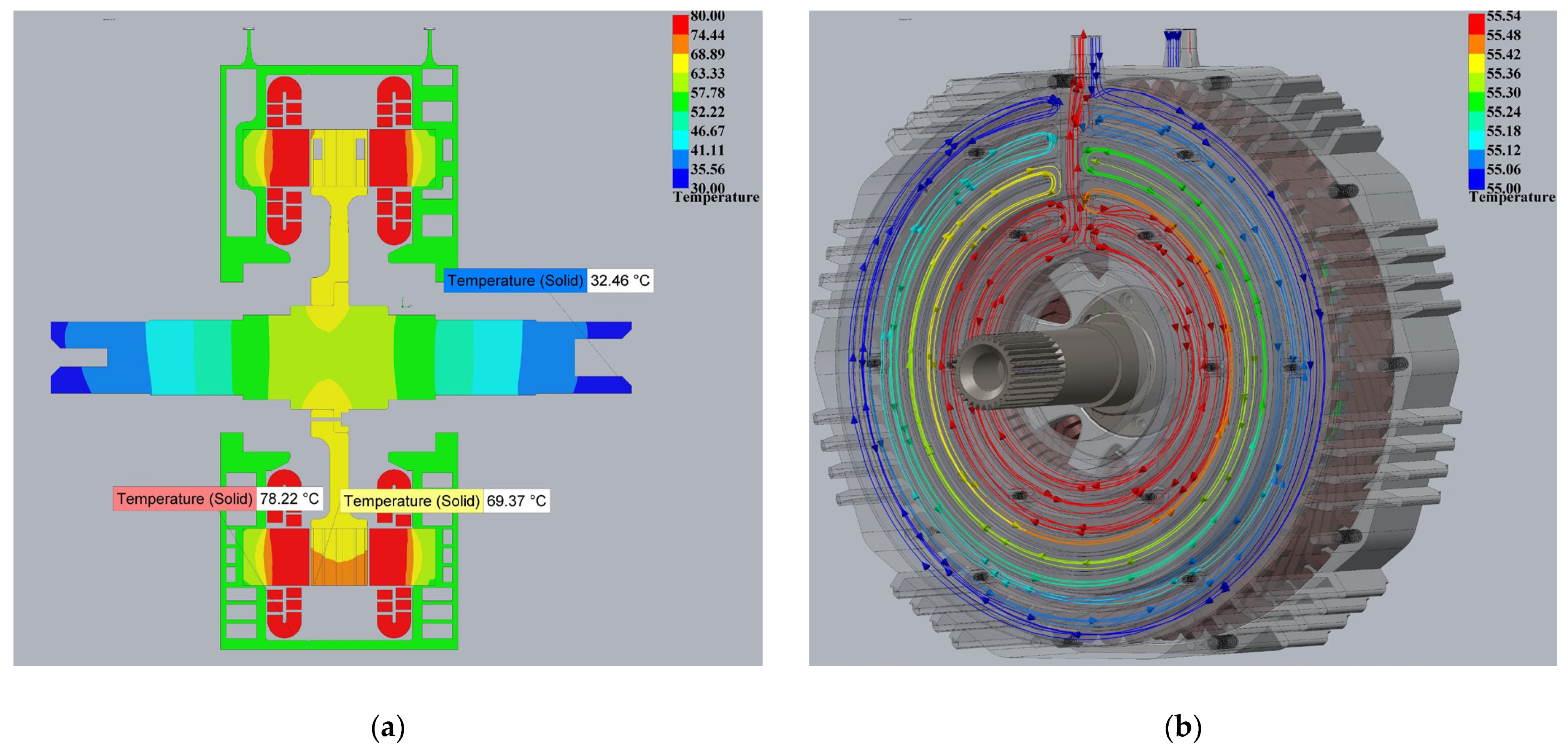
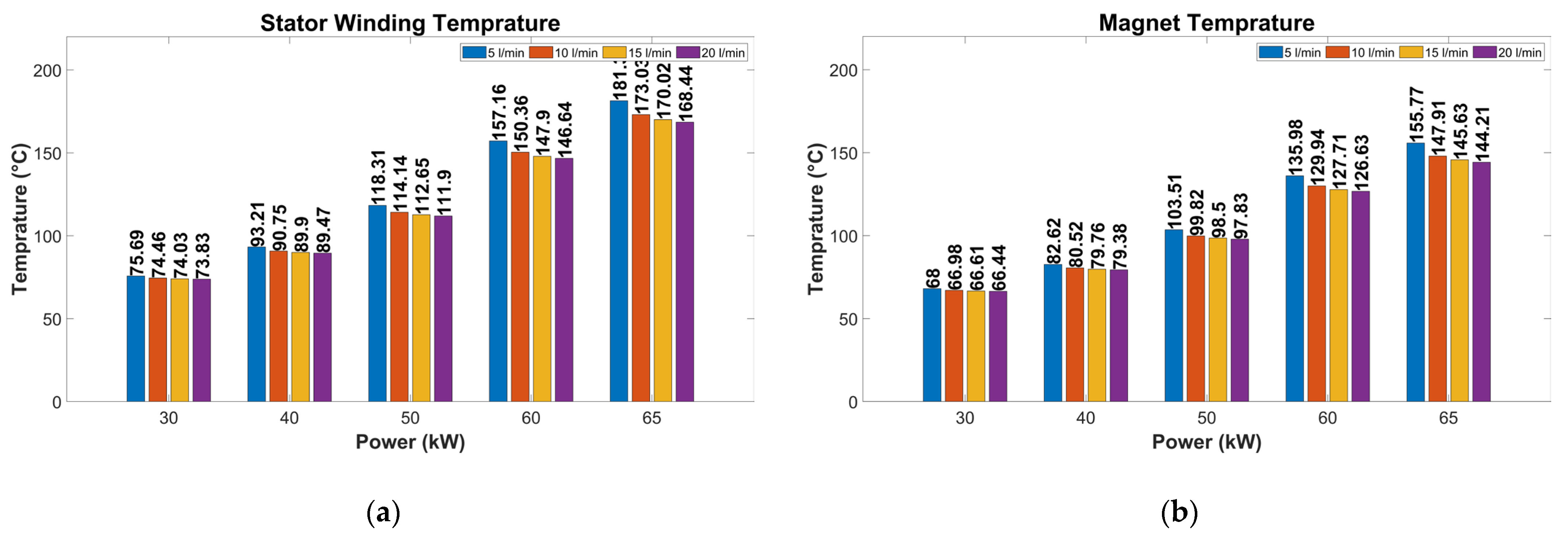
3.3. Thermal Analyses of the AF-Pma-SynRM Model

The final part of the AF-Pma-SynRM multi-physics analysis is the thermal analysis. The forced liquid method aims to cool the AF-Pma-SynRM, which is electromagnetically and mechanically sufficient. As shown in Figure 7, it seeks to cool the stator and the most significant heat source, motor windings, with liquid channels (liquid cooling jacket) directly contacting the stator yokes [30]. The cooling jacket is designed using the tandem channel method, which is suitable for double-stator axial flux machines [14,31].
The biggest problem in tandem channel design is the presence of dead zones in the turning areas of the channel [32]. To prevent this, the channels are designed to overlap. Roy et al. [31], obtained better thermal results with the tandem channel design than the channel models featuring spoilers, helical elements, and a Z-shape [31].
Magnetic and mechanical losses in motors are a source of heat [21,30]. Table 3 shows the losses (W/m3) of the stator, rotor, windings, and magnets of the AF-Pma-SynRM model from a nominal power of 30 kW to a peak power of 65 kW by volume. The stator/rotor steel, copper windings, and magnet (N42SH) thermal conductivities are 25 Wm-C, 400 Wm-C, and 8.7 Wm-C, respectively.
Figure 9 shows the thermal results of the AF-Pma-SynRM model without cooling at 30 kW nominal power. At an ambient temperature of 25 °C, the maximum temperature was measured as 161.39 °C at the stator windings, 143.51 °C at the magnet, and 143.95 °C at the stator yoke. According to IEC 60034-1, the maximum allowed temperature of the stator windings with H class insulation is 180 °C [33]. Also the maximum allowed temperature of the N42SH magnet is 150 °C [34,35]. The winding and magnet temperatures are still below the thermal limits at the rated motor power of 30 kW. However, cooling will be required at higher power levels.
In this forced liquid jacket cooling system, thermal analyses were performed at different flow rates of 5 L/min, 10 L/min, 15 L/min, and 20 L/min [31]. The preferred coolant was a mixture of ethylene glycol and water (EGW 50/50%). EGW is a suitable coolant for EVs, with a boiling point of 106 °C and a freezing point of −37 °C [21,28,30]. EGW for EV is pumped externally to the system in a closed-loop system. For this reason, the average temperature of the EGW is set at 55 °C [28,34].
Figure 10 shows the thermal analysis results for the AF-Pma-SynRM model with a flow rate of 20 L/min, which gives the best thermal results for a nominal power of 30 kW. Figure 10a shows the temperature of the motor winding and magnets without cooling, which were 161.4 °C and 142.4 °C, respectively. With cooling applied, these temperatures decreased to 73.83 °C and 66.44 °C, respectively. In Figure 10b, when the cooling liquid is supplied to the system at a flow rate of 20 L/min, it has an inlet temperature of 55 °C and an outlet temperature of 55.54 °C. The lowest temperature measured is 49.84 °C at the motor shaft.
This study investigated the thermal performance of the AF-PMa-SynRM at different power levels. The analysis revealed that copper losses increased significantly at higher current levels and emerged as the primary heat source. To observe temperature changes at different speeds, the motor model analyzed at a nominal speed of 3000 rpm (see Figure 10) was evaluated at a maximum speed of 10,000 rpm.
The same 81.3 Arms current and 20 L/min flow rate of cooling fluid were used in both analyses to evaluate thermal changes. The analysis results obtained at maximum speed are presented in Figure 11. In this case, it was observed that the copper losses (706,741 W/m3) remained similar to the nominal speed values. However, there was a 266% increase in stator core losses (303,308 W/m3) due to hysteresis and eddy currents. Due to direct contact between the cooling channels and the stator, temperature increases in the winding and rotor regions were measured to be only 3.22 °C and 2.26 °C, respectively.
Figure 12 shows the thermal analysis results for the AF-Pma-SynRM model with a flow rate of 20 L/min, which gives the best thermal results for a peak power of 65 kW. In Figure 12a, the maximum temperature of the motor winding and magnets were measured to be 174.52 °C and 146.46 °C, respectively. In Figure 12b, when the cooling fluid was supplied to the system at a flow rate of 20 L/min, it had an inlet temperature of 55 °C and an outlet temperature of 57.45 °C. The lowest temperature measured was 45.43 °C at the motor shaft.
Figure 13 shows the thermal results of the AF-Pma-SynRM model for 30 kW, 40 kW, 50 kW, 60 kW, and 65 kW power ratings at 5 L/min, 10 L/min, 15 L/min, and 20 L/min coolant flow rates. The motor windings and magnet temperature decrease as the fluid flow rate increases. The 74 kW peak power determined from the electromagnetic results is not shown in Figure 13, as it is well above the thermal limits.
As the coolant flow rate increases, the motor temperature decreases. The change in temperature with the flow rate is most evident for the 65 kW model. Increasing the coolant flow rate from 5 L/min to 10, 15, and 20 L/min caused the average motor winding temperature to decrease by 4.6%, 6.2%, and 7.1%, respectively, as shown in Figure 13a. As demonstrated in Figure 13b, the average magnet temperature decreased by 5.1%, 6.5%, and 7.4%, respectively.
In a motor model with a flow rate of 20 L/min, the average motor winding temperatures for 30 kW, 40 kW, 50 kW, 60 kW and 65 kW of power were measured as 73.83 °C, 89.47 °C, 111.9 °C, 146.64 °C, and 168.44 °C, respectively. Similarly, the average magnet temperatures were 66.44 °C, 79.38 °C, 97.83 °C, 126.63 °C, and 144.21 °C, respectively. In this case, the 65 kW model with a 168.44 °C motor winding temperature and 144.21 °C magnet temperature is within our thermal limits (180 °C winding temperature and 150 °C magnet temperature). The 65 kW model cooled with only a 5 L/min flow rate was below the thermal limits, with a 181.36 °C motor winding temperature and 155.77 °C magnet temperature. Although the AF-Pma-SynRM model achieved a peak power of 74 kW in the electromagnetic analysis, the peak power was revised to 65 kW due to the thermal analysis.

4. Conclusions

In this study, the AF-Pma-SynRM model is designed for EVs. This design uses the NS torus topology with a double air gap (double stator). The axial model has been demonstrated to reduce volumes. Moreover, a magnet-assisted structure is preferred to achieve high power and torque density. The AF-Pma-SynRM model contributes to the literature with a rotor barrier structure suitable for mass production. Axial flux motors have a conical structure that decreases from the outer diameter to the inner diameter. The structural design of the motor results in the volumetric reduction of the stator teeth, magnets, and barrier from the outer diameter to the inner diameter. This phenomenon presents challenges during the motor manufacturing process. The present study proposes a solution to this issue by designing rotor barriers and magnets so that their dimensions remain constant from the outer diameter to the inner diameter. This innovative design has been developed to facilitate mass production.
The performance of the AF-Pma-SynRM model is optimized by the multi-objective optimization of the rotor barriers, with the objective functions being a high torque, high efficiency, and low torque ripple. The optimization results show that a torque value of 95.6 Nm and a rated power of 30 kW are obtained at a rated speed of 3000 rpm. The maximum speed measured was 10,000 rpm, with a maximum torque value of 253.1 Nm and a maximum power value of 74 kW. The AF-Pma-SynRM model shows a maximum efficiency of 94.4% in the range of approximately 3000 to 5000 rpm. The analysis also indicates a maximum constant torque region of 253.1 Nm from the starting speed to the rated speed and a minimum constant power region of 45 kW from the rated speed to the maximum speed. The calculated CPSR is 3.3.
The conclusions based on the results of the electromagnetic analyses of the AF-Pma-SynRM model have been obtained, and multi-physics analyses were performed by testing the mechanical and thermal capabilities of the final model. Stress analyses were conducted on the shaft, rotor sleeve, and the rotor with the new barrier structure. The motor shaft, which was found to be 5.44 times more reliable according to bending analyses, was evaluated as 4.31 times safer in torsion stress analyses. Similarly, the safety factor was calculated to be 9.67 due to torsion stress analyses on the rotor. In addition, the safety factor of the CFRP sleeve rotor was 2.77, as determined by the bending analysis. The cooling jacket method was considered for the mechanical model design, and cooling channels were added to the motor covers in contact with the stator yokes.
The thermal analyses of the AF-Pma-SynRM model, whose electromagnetic and mechanical analyses were completed, were first performed without cooling at a nominal power value of 30 kW. As a result of the studies performed without cooling, it was found that the average winding temperature was 161.69 °C and the magnet temperature was 143.51 °C. Notably, the winding and magnet thermal limits are 180 °C and 150 °C, respectively. These findings indicate that thermal qualification was achieved without cooling at the nominal power value. For higher power values, liquid cooling with a mixture of ethylene glycol and water (50–50%) was preferred in a closed-loop system with an inlet temperature of 55 °C. The maximum power value of the AF-Pma-SynRM model was determined to be 65 kW as a result of the thermal analyses. The motor model, which can reach a peak power of 74 kW electromagnetically, thermally remained at a 65 kW power value. The changes in winding and magnet temperatures from a nominal power of 30 kW to a peak power of 65 kW were found to be 128% and 117%, respectively, at the highest flow rate. It was determined that an increase in the coolant flow rate from 5 L/min to 20 L/min resulted in a 7.1% positive change in the winding temperature at maximum power.
This study has realized the design of the AF-Pma-SynRM model for EVs. A rotor barrier structure suitable for mass production has been developed, contributing to the existing literature on the subject. Multi-objective optimization and multi-physics analyses of the model have been performed. This study is thought to increase the use of similar models of axial flux motors in the future.

Author Contributions

Conceptualization, M.A. and E.G.; methodology, M.A.; software, E.G.; validation, M.A.; formal analysis, E.G.; investigation, M.A.; resources, E.G.; data curation, E.G.; writing—original draft preparation, E.G.; writing—review and editing, M.A.; visualization, E.G.; supervision, M.A.; project administration, M.A. All authors have read and agreed to the published version of the manuscript.

Funding

This research received no external funding.

Data Availability Statement

The original contributions presented in this study are included in the article. Further inquiries can be directed to the corresponding author(s).

Conflicts of Interest

The authors declare no conflicts of interest.

References

  1. Nishanth, F.; Van Verdeghem, J.; Severson, E.L. A Review of Axial Flux Permanent Magnet Machine Technology. IEEE Trans. Ind. Appl. 2023, 59, 3920–3933. [Google Scholar] [CrossRef]
  2. Shao, L.; Navaratne, R.; Popescu, M.; Liu, G. Design and Construction of Axial-Flux Permanent Magnet Motors for Electric Propulsion Applications—A Review. IEEE Access 2021, 9, 158998–159017. [Google Scholar] [CrossRef]
  3. Jenkins, C.; Jones-Jackson, S.; Zaher, I.; Pietrini, G.; Rodriguez, R.; Cotton, J.; Emadi, A. Innovations in Axial Flux Permanent Magnet Motor Thermal Management for High Power Density Applications. IEEE Trans. Transp. Electrif. 2023, 9, 4380–4405. [Google Scholar] [CrossRef]
  4. Zheng, S.; Zhu, X.; Xiang, Z.; Xu, L.; Zhang, L.; Lee, C.H.T. Technology trends, challenges, and opportunities of reduced-rare-earth PM motor for modern electric vehicles. Green Energy Intell. Transp. 2022, 1, 100012. [Google Scholar] [CrossRef]
  5. Gobbi, M.; Sattar, A.; Palazzetti, R.; Mastinu, G. Traction motors for electric vehicles: Maximization of mechanical efficiency—A review. Appl. Energy 2024, 357, 122496. [Google Scholar] [CrossRef]
  6. Zou, T.; Gerada, D.; Rocca, S.L.; Rocca, A.L.; Walker, A.; Vakil, G.; Arevalo, S.L.; Xu, Z.; Cui, M.; Bardalai, A.; et al. Airgap Length Analysis of a 350 kw PM-Assisted Syn-Rel Machine for Heavy Duty EV Traction. IEEE Trans. Ind. Appl. 2023, 59, 1557–1570. [Google Scholar] [CrossRef]
  7. Nyitrai, A.; Kuczmann, M. Magnetic equivalent circuit and finite element modelling of anisotropic rotor axial flux permanent magnet synchronous motors with fractional slot distributed winding. IET Electr. Power Appl. 2023, 17, 709–720. [Google Scholar] [CrossRef]
  8. Katona, M.; Orosz, T. Circular Economy Aspects of Permanent Magnet Synchronous Reluctance Machine Design for Electric Vehicle Applications: A Review. Energies 2024, 17, 1408. [Google Scholar] [CrossRef]
  9. Yilmaz, M. Limitations/capabilities of electric machine technologies and modeling approaches for electric motor design and analysis in plug-in electric vehicle applications. Renew. Sustain. Energy Rev. 2015, 52, 80–99. [Google Scholar] [CrossRef]
  10. Adăscăliței, C.; Marțiș, R.A.; Karaisas, P.; Marțiș, C.S. In-Depth Exploration of Design and Analysis for PM-Assisted Synchronous Reluctance Machines: Implications for Light Electric Vehicles. Machines 2024, 12, 361. [Google Scholar] [CrossRef]
  11. Xing, F.; Zhang, J.; Zhang, M.; Qin, C. Design and Multi-Objective Optimization of an Asymmetric-Rotor Permanent-Magnet-Assisted Synchronous Reluctance Motor for Improved Torque Performance. Appl. Sci. 2024, 14, 6734. [Google Scholar] [CrossRef]
  12. Huynh, T.-A.; Chen, P.-H.; Hsieh, M.-F. Analysis and Comparison of Operational Characteristics of Electric Vehicle Traction Units Combining Two Different Types of Motors. IEEE Trans. Veh. Technol. 2022, 71, 5727–5742. [Google Scholar] [CrossRef]
  13. Song, T.; Zhang, Z.; Liu, H.; Hu, W. Multi-objective optimisation design and performance comparison of permanent magnet synchronous motor for EVs based on FEA. IET Electr. Power Appl. 2019, 13, 1157–1166. [Google Scholar] [CrossRef]
  14. Zhao, J.; Han, Q.; Dai, Y.; Hua, M. Study on the Electromagnetic Design and Analysis of Axial Flux Permanent Magnet Synchronous Motors for Electric Vehicles. Energies 2019, 12, 3451. [Google Scholar] [CrossRef]
  15. Al-ani, M. Multi-physics design and analyses of dual rotor synchronous reluctance machine. eTransportation 2021, 8, 100113. [Google Scholar] [CrossRef]
  16. Luo, L.; Chang, J.; Wu, J.; Zhu, B.; Zheng, M.; Zhang, N. Design and Analysis of a Water-Cooling System in a New Yokeless and Segmented Armature Axial In-Wheel Motor for Electric Vehicles. J. Therm. Sci. Eng. Appl. 2021, 13, 051015. [Google Scholar] [CrossRef]
  17. Wang, Y.; Zhu, T.; Geng, W.; Guo, J.; Sun, Y. Cooling System Analysis of an Enclosed Yokeless Stator for High-Power Axial Flux PM Motor With Distributed Winding. IEEE Trans. Ind. Electron. 2024, 71, 2789–2799. [Google Scholar] [CrossRef]
  18. Ajamloo, A.M.; Ibrahim, M.N.; Sergeant, P. Design, Modelling and Optimization of a High Power Density Axial Flux SRM with Reduced Torque Ripple for Electric Vehicles. Machines 2023, 11, 759. [Google Scholar] [CrossRef]
  19. Özsoy, M.; Kaplan, O.; Akar, M. FEM-based analysis of rotor cage material and slot geometry on double air gap axial flux induction motors. Ain Shams Eng. J. 2024, 15, 102393. [Google Scholar] [CrossRef]
  20. Özsoy, M.; Kaplan, O.; Akar, M. The effect of stator slot number and pole number on motor performance in double-sided axial flux induction motors for electric vehicles. Electr. Eng. 2022, 104, 4289–4304. [Google Scholar] [CrossRef]
  21. Gai, Y.; Kimiabeigi, M.; Chuan Chong, Y.; Widmer, J.D.; Deng, X.; Popescu, M.; Goss, J.; Staton, D.A.; Steven, A. Cooling of Automotive Traction Motors: Schemes, Examples, and Computation Methods. IEEE Trans. Ind. Electron. 2019, 66, 1681–1692. [Google Scholar] [CrossRef]
  22. Eser, E.; Üstkoyuncu, N. Effects of Permanent Magnets on Different Flux Barriers for the AF-SynRMs. Electr. Power Compon. Syst. 2024, 52, 1936–1945. [Google Scholar] [CrossRef]
  23. Geng, W.; Wang, J.; Fu, Y.; Guo, J.; Li, W. Design and Performance Analysis of a Novel Axial-flux IPM Machine for Electric Vehicles. IEEE Trans. Transp. Electrif. 2024, 1, 5569–5577. [Google Scholar] [CrossRef]
  24. Kwon, M.-S.; Lim, D.-K. A Study on the Optimal Design of PMa-SynRM for Electric Vehicles Combining Random Forest and Genetic Algorithm. IEEE Access 2023, 11, 52357–52369. [Google Scholar] [CrossRef]
  25. Song, T.; Liu, H.; Zhang, Q.; Zhang, Z. Multi-physics and multi-objective optimisation design of interior permanent magnet synchronous motor for electric vehicles. IET Electr. Power Appl. 2020, 14, 2243–2254. [Google Scholar] [CrossRef]
  26. Wi, C.-H.; Kim, J.-Y.; Choi, J.-W.; Yeo, H.-K.; Lim, D.-K. Optimal Design of PMa-SynRM for Electric Vehicles Using Grain-Oriented Electrical Steel and Surrogate Model Based on Stacking Ensemble. J. Electr. Eng. Technol. 2023, 18, 991–1001. [Google Scholar] [CrossRef]
  27. Gedara, H. Design Optimization and Performance Improvement of Synchronous Reluctance Machines. Master’s Thesis, University of Manitoba, Winnipeg, MB, Canada, 2019. [Google Scholar]
  28. Özsoy, M. Elektrikli Araçlar için Eksenel Akılı Asenkron Motor Tasarımı, Mekanik ve Isıl Analizi. Ph.D. Thesis, Gazi University, Ankara, Turkey, 2023. [Google Scholar]
  29. Grace, K.; Galioto, S.; Bodla, K.; El-Refaie, A.M. Design and Testing of a Carbon-Fiber-Wrapped Synchronous Reluctance Traction Motor. IEEE Trans. Ind. Appl. 2018, 54, 4207–4217. [Google Scholar] [CrossRef]
  30. Madhavan, S.; Raunak Devdatta, P.B.; Gundabattini, E.; Mystkowski, A. Thermal Analysis and Heat Management Strategies for an Induction Motor, a Review. Energies 2022, 15, 8127. [Google Scholar] [CrossRef]
  31. Roy, R.; Ramasami, S.; Chokkalingam, L.N. Review on Thermal Behavior and Cooling Aspects of Axial Flux Permanent Magnet Motors–A Mechanical Approach. IEEE Access 2023, 11, 6822–6836. [Google Scholar] [CrossRef]
  32. Konda, Y.R.; Ponnaganti, V.K.; Reddy, P.V.S.; Singh, R.R.; Mercorelli, P.; Gundabattini, E.; Solomon, D.G. Thermal Analysis and Cooling Strategies of High-Efficiency Three-Phase Squirrel-Cage Induction Motors—A Review. Computation 2024, 12, 6. [Google Scholar] [CrossRef]
  33. IEC 60034-1; Rotating Electrical Machines—Part 11: Thermal Protection. International Electrotechnical Commission (IEC): Geneva, Switzerland, 2020.
  34. Sun, Y.; Zhang, S.; Chen, G.; Tang, Y.; Liang, F. Experimental and numerical investigation on a novel heat pipe based cooling strategy for permanent magnet synchronous motors. Appl. Therm. Eng. 2020, 170, 114970. [Google Scholar] [CrossRef]
  35. Avsar, Y.; Fenercioglu, A.; Soyaslan, M. Design Optimization of PM Synchronous Motor: Rail Mounted Belt Drive Elevator Systems. IEEE Trans. Ind. Appl. 2023, 60, 301–311. [Google Scholar] [CrossRef]
Figure 1. AF-Pma-SynRM initial design flowchart.
Machines 13 00555 g001
Figure 2. AF-Pma-SynRM model design.
Machines 13 00555 g002
Figure 3. Multi-physics analysis flowchart.
Machines 13 00555 g003
Figure 4. AF-Pma-SynRM 1/10 model rotor barrier structure and parameters.
Machines 13 00555 g004
Figure 5. Results of the AF-Pma-SynRM optimization.
Machines 13 00555 g005
Figure 6. AF-Pma-SynRM model: (a) efficiency map and (b) constant torque–power curve.
Machines 13 00555 g006
Figure 7. Exploded view of the AF-Pma-SynRM model mechanical design.
Machines 13 00555 g007
Figure 8. AF-Pma-SynRM model stress-displacement analyses: (a) shaft bending stress analysis; (b) shaft torsion stress analysis; (c) rotor torsion stress analysis; and (d) rotor sleeve torsion stress analysis.
Machines 13 00555 g008
Figure 9. AF-Pma-SynRM 30 kW-rated model without a cooling thermal analysis.
Machines 13 00555 g009
Figure 10. Thermal analysis of the AF-Pma-SynRM model with a nominal power of 30 kW and a 20 L/min flow: (a) cross-section of the motor temperature distribution and (b) thermal change of the coolant.
Machines 13 00555 g010
Figure 11. Thermal analysis of the AF-Pma-SynRM model at a peak speed of 10,000 rpm and 20 L/min flow: (a) cross-section of the motor temperature distribution and (b) thermal change of the coolant.
Machines 13 00555 g011
Figure 12. Thermal analysis of the AF-Pma-SynRM model at a peak power of 65 kW and 20 L/min flow: (a) cross-section of the motor temperature distribution and (b) thermal change of the coolant.
Machines 13 00555 g012
Figure 13. AF-Pma-SynRM model at different flow rates and different power ratings: (a) average stator winding temperature and (b) average magnet temperature.
Machines 13 00555 g013
Table 1. Key specifications of the AF-Pma-SynRM model.
ParametersValue
Poles/Slot10/60
Outer Diameter (mm)/Inner Diameter (mm)242/181.5
Stator Axial Length (mm)/Rotor Axial Length (mm)35 × 2/30
Airgap Length (mm)1
Rated Speed (rpm)/Peak Speed (rpm)3000/10,000
Rated Power (kW)/Peak Power (kW)30/65
Rated Torque (Nm)/Peak Torque (Nm)95/253
Rated Phase Current (Arms)/Peak Phase Current (Arms)81.3/200
Stator Material (Laminated)/Rotor Material (Laminated)JFE_Steel_35JN230
Lamination Stacking Factor0.97
Stator Weight (kg)/Rotor Weight (kg)6.76/2.26
MagnetsN42SH
Magnet 1 (Bottom Barrier) Weight (kg)/Magnet 2 (Top Barrier) Weight (kg)0.0517/0.0257
Stator Windings MaterialCopper
Stator Windings Material Weight (kg)9.64
Table 2. Variable parameters of the AF-Pma-SynRM, optimization limit values, and optimized values.
ParametersInitial ValueMinimum LimitMaximum LimitOptimized Value
b1 (mm)7.577.97.281709009
b2 (mm)1.5121.359964308
y1 (mm)6.2474.273731954
y2 (mm)3.2354.578323399
y3 (mm)40304638.40619239
y4 (mm)25203026.29369015
m3 (mm)37254537.17054926
m4 (mm)22152924.01390593
z3 (mm)7576.027811951
z4 (mm)434.94.654978277
rot1 (degree °)14.5141514.853
rot2 (degree °)9.59109.94377551
Table 3. AF-Pma-SynRM model losses at different powers.
ModelVolume (m3)Losses W/m3
30 kW40 kW50 kW60 kW65 kW
Stator8.8862 × 10−482,625.4294,553.92115,899.93131,152.8138,735.34
Rotor2.9702 × 10−45630.028885.3310,877.1513,001.7813,898.73
Winding8.9461 × 10−6690,053.771283,911.432,137,635.393,474,989.14,280,021.46
Magnet 16.8132 × 10−51210.711088.12095.995540.337558.55
Magnet 23.3885 × 10−53575.835205.735382.386021.316829.1
Disclaimer/Publisher’s Note: The statements, opinions and data contained in all publications are solely those of the individual author(s) and contributor(s) and not of MDPI and/or the editor(s). MDPI and/or the editor(s) disclaim responsibility for any injury to people or property resulting from any ideas, methods, instructions or products referred to in the content.

