
Cascaded H-Bridge Multilevel Converter Topology for a PV Connected to a Medium-Voltage Grid


Abstract
1. Introduction
1.1. Overview
1.2. Literature Review
- The ability to increase the system voltage/power without requiring significant modifications to the system.
- In the case of some PV panels being shaded, the other modules will not be affected.
- Each module has its own controller, which increases flexibility.
- In terms of faults, faulty modules can be bypassed.
- The proposed topology can be fit to different renewable energy sources.
1.3. Paper Contribution
- ○
- An isolated MV-MLC is presented in this paper for medium-voltage PV applications. Compared to existing solutions, the proposed method provides a reduction in the double-frequency voltage on the DC link capacitor, a reduction in the required DC link capacitor, and a reduction in the transformer core size.
- ○
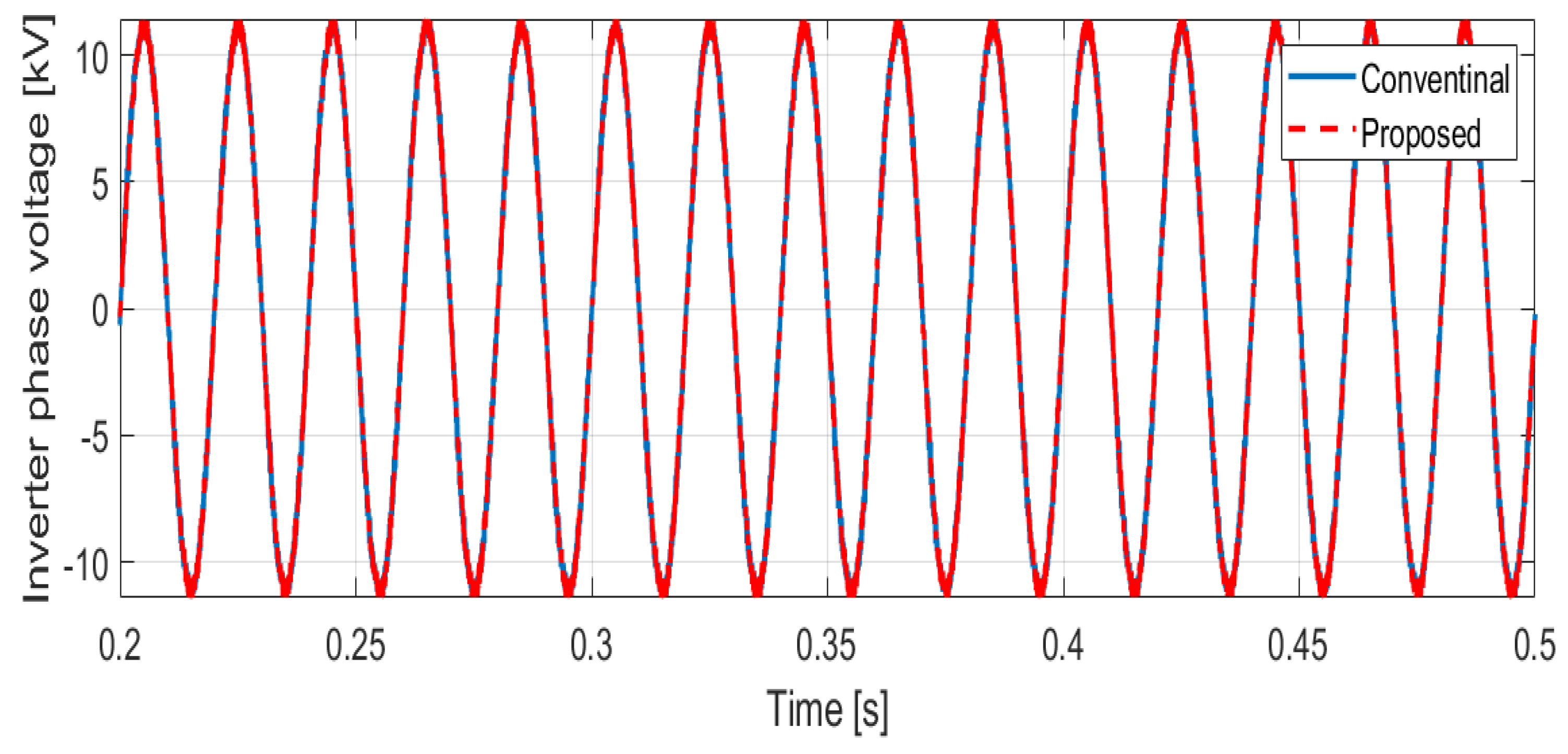
- The proposed configuration produces high-quality voltage and current waveforms with lower THD distortion and higher reliability.
- ○
- Compared to existing PV grid integration solutions, the proposed method provides better utilization of the PV output power and better performance under partially shaded PV panels. Moreover, the proposed configuration eliminates the interphase imbalance that exists in conventional solutions.
2. Proposed Multilevel Converters
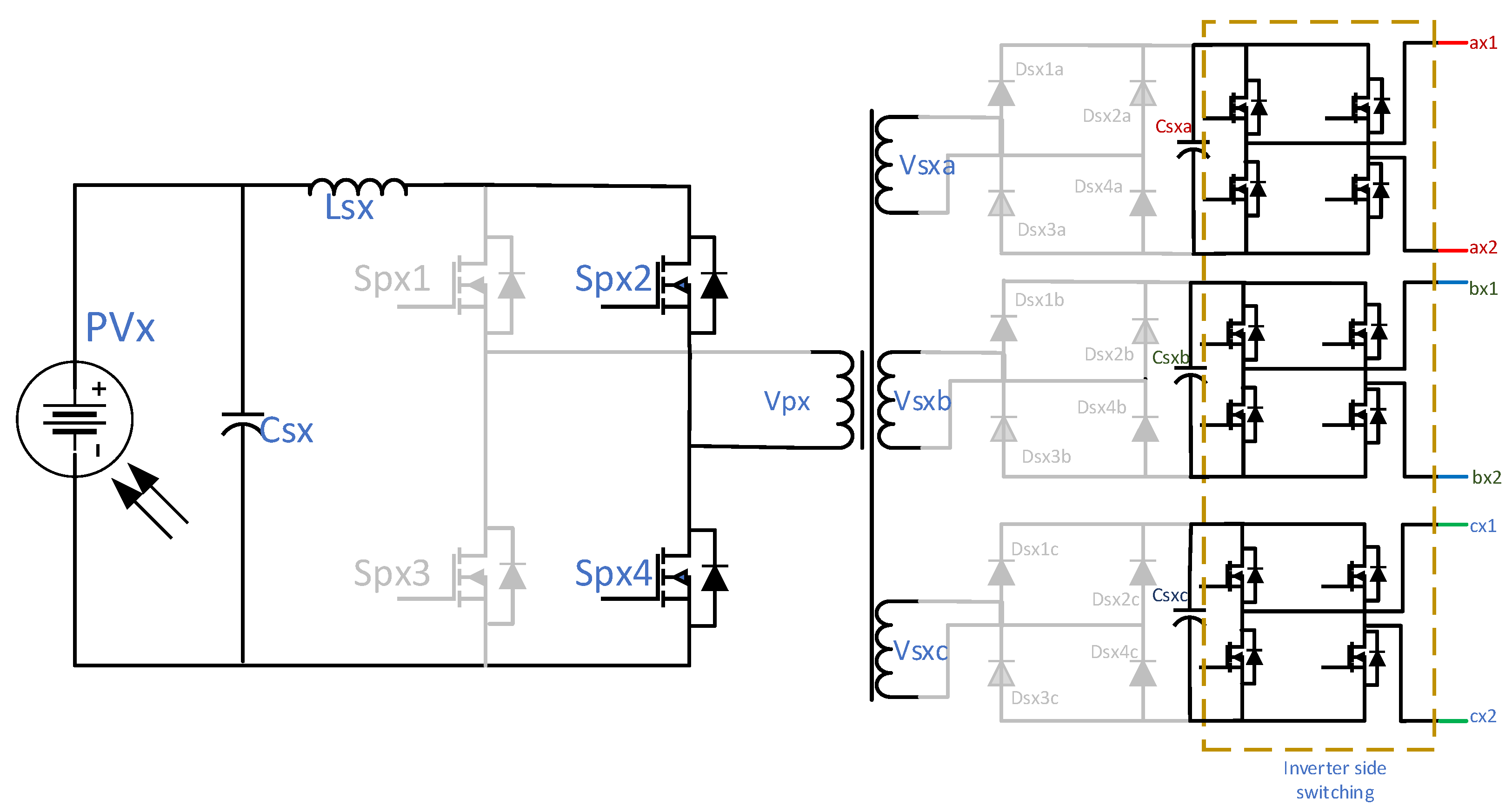
2.1. The Proposed MLC Circuit and Configuration
2.2. Operation of the Proposed MLC
- Mode 1: This mode is started by activating switches SPX1 and SPX3, which initiates charging of the choke coil (LSX), causing its current to rise linearly. Simultaneously, the secondary-side DC link capacitor discharges to maintain power delivery to the load, ensuring continuous energy supply while the inductor stores energy, as shown in Figure 3.
- Mode 2: When SPX1 and SPX4 are turned ON, the choke coil discharges its stored energy into the transformer’s primary winding. This action generates a positive voltage across the winding, enabling power transfer to the load through the secondary-side diode rectifier, as shown in Figure 4.
- Mode 3: Activating switches SPX2 and SPX4 re-energizes the choke coil, inducing a monotonic increase in the inductor current. The DC link capacitor exclusively sustains the load current during this interval, as shown in Figure 5.
- Mode 4: Conduction of SPX2 and SPX3 discharges the choke coil energy into the transformer winding, inducing a negative voltage across its primary winding. The transformer transfers this energy to the load through the secondary-side diode rectifier, as shown in Figure 6. The duty cycle is generated from the MPPT algorithm.
2.3. System Design
- A.
- Number of Voltage Levels Design
- B.
- Transformer Design
- Initially, the converter rated power, input, and output voltages are entered into the algorithm. Additionally, all constants used in the design are specified.
- The design constraints are established, along with the initial flux density and operating frequency. Using these initial values, the dimensions of the transformer core are calculated.
- Using the transformer dimensions, the core and copper losses are calculated.
- The power electronics losses are calculated.
- Based on the power electronics losses, the heat sink volume is then calculated. All the volumes and losses are determined. Depending on the optimization target (minimum losses or minimum volume), the optimization is carried out until the end criteria are met.
- The end criteria are the value difference between successive iterations, the number of iterations, and the constraints tolerance.
- 2.
- Obtaining the voltage per turn of the transformer using Equation (1):
- 3.
- Calculating the transformer core cross-sectional area and the transformer core window area using Equations (2) and (3):
- 4.
- Finding the transformer core volume using Equation (4):
- C.
- Passive Elements Design
- D.
- Closed-Loop Control
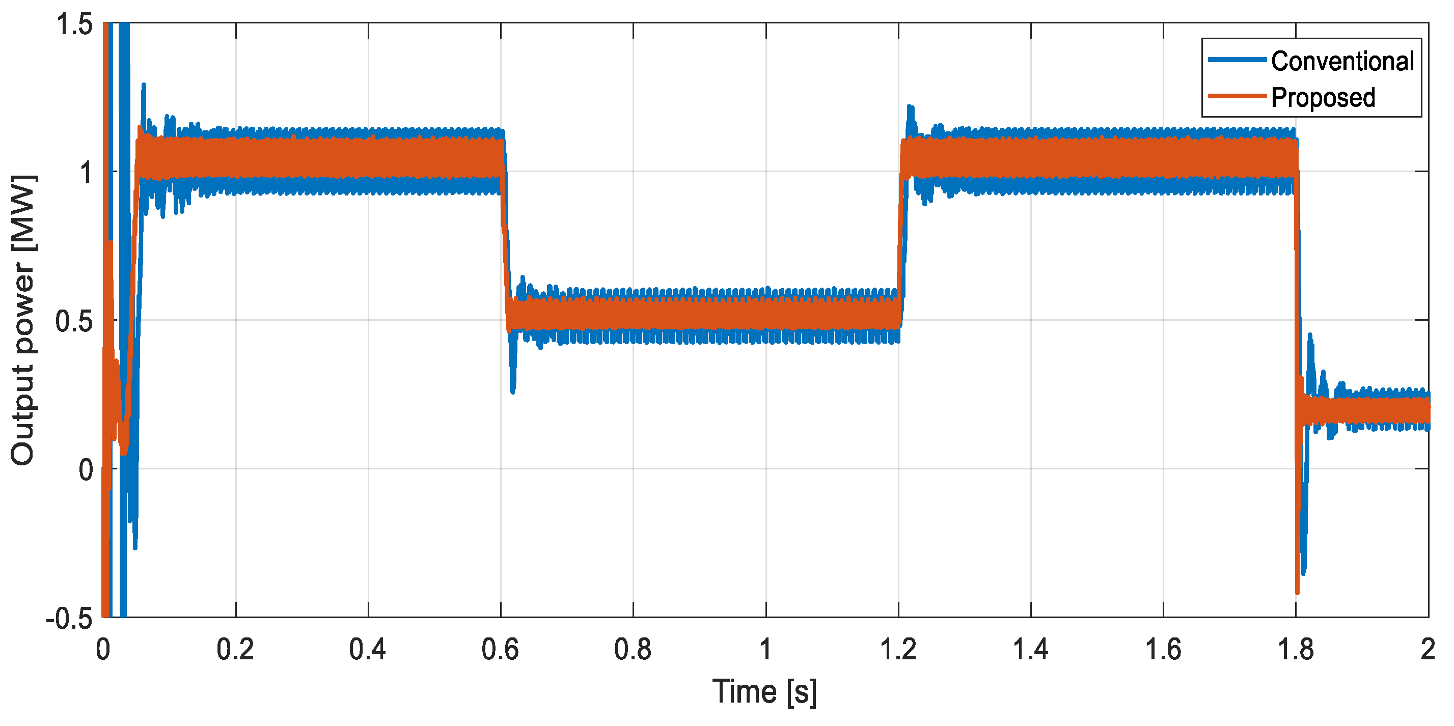
3. Simulation Results
- Based on the authors’ knowledge, it is not much work to address the problem of a double-frequency harmonic MLC.
- Recent work on MLCs employing high-frequency transformers focusing on improving the power density of the converter and control is not mature and has some drawbacks, such as the complexity of the system.
- Due to the simplicity of the proposed converter in terms of control and operation, the convention MLC is a suitable converter to compare with, as they share the same simplicity in terms of control and operation.
4. Discussion
- ○
- The price of the converter could be higher than a conventional one due to a large number of power electronics switches and using a special core for the HFT. Mass production can reduce the converter price.
- ○
- The losses of the proposed converter could be higher than an ordinary converter. Employing a lower-loss transformer core (at high frequency) and using WBG devices can reduce the total losses.
5. Conclusions
Author Contributions
Funding
Data Availability Statement
Conflicts of Interest
References
- Tlili, I. Renewable energy in Saudi Arabia: Current status and future potentials. Environ. Dev. Sustain. 2015, 17, 859–886. [Google Scholar] [CrossRef]
- General Authority for Statistics. Available online: https://www.stats.gov.sa (accessed on 27 July 2024).
- Al Zohbi, G.; Al Amri, F.G. Current situation of renewable energy in Saudi Arabia: Opportunities and challenges. Sustain. Dev. 2020, 13, 1913–9071. [Google Scholar] [CrossRef]
- Rahman, F.; Rehman, S.; Abdul-Majeed, M.A. Overview of energy storage systems for storing electricity from renewable energy sources in Saudi Arabia. Renew. Sustain. Energy Rev. 2012, 16, 274–283. [Google Scholar] [CrossRef]
- Barhoumi, E.M.; Okonkwo, P.C.; Zghaibeh, M.; Belgacem, I.B.; Alkanhal, T.A.; Abo-Khalil, A.G.; Tlili, I. Renewable energy resources and workforce case study Saudi Arbia; review and recommendations. J. Therm. Anal. Calorim. 2020, 141, 221–230. [Google Scholar] [CrossRef]
- Khalid, A.K.; Quamar, M.M.; Al-Qahtani, F.H.; Asif, M.; Alqahtani, M.; Khalid, M. Smart grid infrastructure and renewable energy deployment: A conceptual review of Saudi Arabia. Energy Strategy Rev. 2023, 50, 101247. [Google Scholar] [CrossRef]
- Al-Ismail, F.S.; Alam, M.S.; Shafiullah, M.; Hossain, M.I.; Syed, M.R. Impacts of renewable energy generation on greenhouse gas emissions in Saudi Arabia: A comprehensive review. Sustainability 2023, 15, 5069. [Google Scholar] [CrossRef]
- Salvador, A.; Busquets-Monge, S.; Nicolás-Apruzzese, J.; Filbà-Martínez, A.; Bordonau, J.; Yuan, X.; Kouro, S. A Survey on Capacitor Voltage Control in Neutral-Point-Clamped Multilevel Converters. Electronics 2022, 11, 527. [Google Scholar] [CrossRef]
- Maosong, Z.; Cui, Y.; Wang, Q.; Tao, J.; Wang, X.; Zhao, H.; Li, G. A Study on Neutral-Point Potential in Three-Level NPC Converters. Energies 2019, 12, 3367. [Google Scholar] [CrossRef]
- Alotaibi, S.; Darwish, A. Modular multilevel converters for large-scale grid-connected photovoltaic systems: A review. Energies 2021, 14, 6213. [Google Scholar] [CrossRef]
- Xiao, B.; Hang, L.; Mei, J.; Riley, C.; Tolbert, L.M.; Ozpineci, B. Modular cascaded H-bridge multilevel PV inverter with distributed MPPT for grid-connected applications. IEEE Trans. Ind. Appl. 2015, 51, 1722–1731. [Google Scholar] [CrossRef]
- Kartick, J.C.; Sujit, B.K.; Suparna, K.C. Dual reference phase shifted pulse width modulation technique for a N-level inverter based grid connected solar photovoltaic system. IET Renew. Power Gener. 2016, 10, 928–935. [Google Scholar] [CrossRef]
- Amaral, F.V.; Parreiras, T.M.; Lobato, G.C.; Machado, A.A.P.; Pires, I.A.; De Jesus Cardoso Filho, B. Operation of a Grid-Tied Cascaded Multilevel Converter Based on a Forward Solid-State Transformer under Unbalanced PV Power Generation. IEEE Trans. Ind. Appl. 2018, 54, 5493–5503. [Google Scholar] [CrossRef]
- Fuentes, C.D.; Rojas, C.A.; Renaudineau, H.; Kouro, S.; Perez, M.A.; Meynard, T. Experimental Validation of a Single DC Bus Cascaded H-Bridge Multilevel Inverter for Multistring Photovoltaic Systems. IEEE Trans. Ind. Electron. 2017, 64, 930–934. [Google Scholar] [CrossRef]
- Liu, L.; Li, H.; Xue, Y.; Liu, W. Decoupled active and reactive power control for large-scale grid-connected photovoltaic systems using cascaded modular multilevel converters. IEEE Trans. Power Electron. 2015, 30, 176–187. [Google Scholar] [CrossRef]
- Shi, Y.; Li, R.; Xue, Y.; Li, H. High-Frequency-Link-Based grid-ties PV system with small DC-link capacitor and low-frequency ripple-free maximum power point tracking. IEEE Trans. Power Electron. 2016, 31, 328–339. [Google Scholar] [CrossRef]
- Sochor, P.; Akagi, H.; Tan, N. Low-voltage-ride-through control of a modular multilevel SDBC inverter for utility-scale photovoltaic systems. In Proceedings of the IEEE Energy Conversion Congress and Exposition (ECCE), Cincinnati, OH, USA, 1–5 October 2017. [Google Scholar] [CrossRef]
- Rabiul-Islam, M.; Guo, Y.; Zhu, J. A high-frequency link multilevel cascaded medium-voltage converter for direct grid integration of renew able energy systems. IEEE Trans. Power Electron. 2014, 29, 4167–4182. [Google Scholar] [CrossRef]
- Rabiul-Islam, M.; Mahfuz-Ur-Rahman, A.M.; Mazharul-Islam, M.; Guo, Y.G.; Zhu, J.G. Modular medium-voltage grid-connected converter with improved switching techniques for solar photovoltaic systems. IEEE Trans. Ind. Electron. 2017, 64, 8887–8896. [Google Scholar] [CrossRef]
- Kouro, S.; Fuentes, C.; Perez, M.; Rodriguez, J. Single DC-link cascaded H-bridge multilevel multistring photovoltaic energy conversion system with inherent balanced operation. In Proceedings of the 38th Annual Conference on IEEE Industrial Electronics Society, Montreal, QC, Canada, 25–28 October 2012. [Google Scholar] [CrossRef]
- Rashwan, A. A new topology for the large-scale photovoltaic systems grid connection based on modular multilevel converter. In Proceedings of the 20th International Middle East Power Systems Conference (MEPCON), Cairo, Egypt, 18–20 December 2018. [Google Scholar] [CrossRef]
- Rivera, S.; Wu, B.; Lizana, R.; Kouro, S.; Perez, M.; Rodriguez, J. Modular multilevel converter for large-scale multistring photovoltaic energy conversion system. In Proceedings of the IEEE Energy Conversion Congress and Expositionthe, Denver, CO, USA, 15–19 September 2013. [Google Scholar] [CrossRef]
- Rong, F.; Gong, X.; Huang, S. A novel grid-connected PV system based on MMC to get the maximum power under partial shading conditions. IEEE Trans. Power Electron. 2017, 32, 4320–4333. [Google Scholar] [CrossRef]
- Bayat, H.; Yazdani, A. A power mismatch elimination strategy for an MMC-based photovoltaic system. IEEE Trans. Energy Convers. 2018, 33, 1519–1528. [Google Scholar] [CrossRef]
- Elsanabary, A.I.; Konstantinou, G.; Mekhilef, S.; Townsend, C.D.; Seyedmahmoudian, M.; Stojcevski, A. Medium Voltage Large-Scale Grid-Connected Photovoltaic Systems Using Cascaded H-Bridge and Modular Multilevel Converters: A Review. IEEE Access 2020, 8, 223686–223699. [Google Scholar] [CrossRef]
- Lu, H.; Xiao, X.; Tang, G.; He, H.; Lin, Z.; Gao, C.; Zheng, Z. Transient Voltage Support Strategy of Grid-Forming Medium Voltage Photovoltaic Converter in the LCC-HVDC System. CSEE J. Power Energy Syst. 2024, 10, 1849–1864. [Google Scholar]
- Lumbreras, D.; Barrios, E.L.; Balda, J.; Navarrete, M.; González, R.; Sanchis, P. Medium-Voltage Cascaded Sequential Topology for Large-Scale PV Plants. IEEE Access 2021, 9, 130601–130614. [Google Scholar] [CrossRef]
- Wang, C.; Li, L. Efficient DC Voltage Balancing of Cascaded Photovoltaic System Based on Predictive Modulation Strategy. IEEE Trans. Ind. Electron. 2024, 71, 1514–1524. [Google Scholar] [CrossRef]
- Adnan, M.; Magableh, K.; Radwan, A.; Abdel-Rady, Y.; Mohamed, I. Assessment and Mitigation of Dynamic Instabilities in Single-Stage Grid-Connected Photovoltaic Systems with Reduced DC-Link Capacitance. IEEE Access 2021, 9, 55522–55536. [Google Scholar]
- Elsanabary, A.; Mekhilef, S.; Aly, M.; Rodriguez, J. Submodule Voltage Balancing Technique of Solar MMC for Firing the Switches Using Integrated PWM Modules. In Proceedings of the IEEE Applied Power Electronics Conference and Exposition (APEC), Atlanta, GA, USA, 16–20 March 2025; pp. 746–750. [Google Scholar] [CrossRef]
- Elsanabary, A.; Mekhilef, S.; Fadilah, N.; Aziz, A. Internal Power Balancing of an MMC-Based Large-Scale PV System Under Unbalanced Voltage Sags. IEEE Emerg. Sel. Top. Power Electron. 2024, 12, 3729–3739. [Google Scholar] [CrossRef]
- Xia, Q.; Debnath, S.; Saeedifard, M. A Neural Network-Based Power Mismatch Elimination Strategy for Integrated Solar and ESS AC/DC Systems (MARS). IEEE Trans. Ind. Electron. 2025, 72, 6943–6956. [Google Scholar] [CrossRef]
- Elsanabary, A.; Mekhilef, S.; Seyedmahmoudian, M.; Stojcevski, A. A Novel Circuit Configuration for the Integration of Modular Multilevel Converter with Large-Scale Grid-Connected PV Systems. IEEE Trans. Energy Convers. 2024, 39, 3–16. [Google Scholar] [CrossRef]
- Ma, Y.; Xiao, J.; Lin, H.; Wang, Z. A Novel Battery Integration Method of Modular Multilevel Converter with Battery Energy Storage System for Capacitor Voltage Ripple Reduction. IEEE Trans. Ind. Electron. 2021, 68, 12250–12261. [Google Scholar] [CrossRef]
- Liu, Y.; Si, Y.; Zhang, Z.; Liu, C.; Wang, M.; Lei, Q. A Novel Modular Multilevel Converter with Ripple Current Elimination Channels Based on Isolated CLLC Resonant Circuits. IEEE Open J. Power Electron. 2022, 3, 433–449. [Google Scholar] [CrossRef]
- Pei, Z.; Kong, D.; Liu, C.; Liu, C.; Guo, D.; Zhu, D. Hybrid Isolated Modular Multilevel Converter Based Solid-State Transformer Topology With Simplified Power Conversion Process and Uneven Voltage Ratio. IEEE Trans. Power Electron. 2023, 38, 12757–12773. [Google Scholar] [CrossRef]
- Irfan, M.S.; Ahmed, A.; Park, J.H. Power-Decoupling of a Multiport Isolated Converter for an Electrolytic-Capacitorless Multilevel Inverter. IEEE Trans. Power Electron. 2018, 33, 6656–6671. [Google Scholar] [CrossRef]
- Song, S.G.; Lee, I.H.; Park, S.J.; Nam, H.K.; Kang, F.S. The isolated multilevel inverter using common-arm scheme for 3-phase system. In Proceedings of the 7th International Caribbean Conference on Devices, Circuits and Systems, Cancun, Mexico, 28–30 April 2008; pp. 1–5. [Google Scholar]
- Std 519-1981; IEEE Guide for Harmonic Control and Reactive Compensation of Static Power Convertors. American National Standard (ANSI): New York, NY, USA, 1981.
- Std 519-1992; IEEE Recommended Practices and Requirements for Harmonic Control in Electrical Power Systems. American National Standard (ANSI): New York, NY, USA, 1992.
- Std 519-2014; IEEE Recommended Practice and Requirements for Harmonic Control in Electric Power Systems. American National Standard (ANSI): New York, NY, USA, 2014.
- Abdalla, O.H.; Mostafa, A.A.A. Technical Requirements for Connecting Solar Power Plants to Electricity Networks. Innov. Energy Syst. 2019, 27, 1–26. [Google Scholar]
- Hussain, E.; Abusara, M.; Sharkh, S. Design Optimisation of a Current-Fed Solid-State Transformer for MV Grid-Connected Applications. Energies 2021, 14, 3283. [Google Scholar] [CrossRef]
- Hurley, W.G.; Wolfle, W.H.; Breslin, J.G. Optimized transformer design: Inclusive of high-frequency effects. IEEE Trans. Power Electron. 1998, 13, 651–659. [Google Scholar] [CrossRef]
- Nikolov, G.T.; Valchev, V.C. Nanocrystalline magnetic materials versus ferrites in power electronics. Procedia Earth Planet. Sci. 2009, 1, 1357–1361. [Google Scholar] [CrossRef]
- Erickson, R.W.; Maksimovic, D. Transformer design. In Fundamental of Power Electronics; Erickson, R.W., Maksimovic, D., Eds.; Springer International Publishing: Cham, Switzerland, 2020; pp. 485–502. [Google Scholar]
- Santra, S.B.; Chatterjee, D.; Kumar, K.; Bertoluzzo, M.; Sangwongwanich, A.; Blaabjerg, F. Capacitor Selection Method in PV Interfaced Converter Suitable for Maximum Power Point Tracking. IEEE J. Emerg. Sel. Top. Power Electron. 2021, 9, 2136–2146. [Google Scholar] [CrossRef]
- MOSER Electronics. Available online: https://www.mouser.com (accessed on 15 February 2025).


| Reference | Scheme | Advantages | Disadvantages |
|---|---|---|---|
| Refs. [9,10] | Neutral point clamped (NPC) and flying capacitor (FC) topologies |
|
|
| Ref. [11] | CHB topology |
|
|
| Ref. [12] | CHB topology with auxiliary circuit |
|
|
| Ref. [13] | Forward dual-active bridge converter |
|
|
| Ref. [14] | CHB with a common DC link cascaded with a flyback converter |
|
|
| Refs. [15,16] | CHB with current-fed dual-active bridge (DAB) |
|
|
| Ref. [17] | CHB with isolated DC-DC converters |
|
|
| Ref. [18] | CHB with a common high-frequency magnetic link |
|
|
| Ref. [19] | Five-level H-bridge converter with high-frequency magnetic link |
|
|
| Ref. [20] | Multilevel CHB with a single DC input |
|
|
| Ref. [21] | MMC with three legs and boost converters |
|
|
| Ref. [22] | MMC with voltage source H-bridge |
|
|
| Ref. [23] | Parallel structure MMC |
|
|
| Ref. [24] | MMC topology with isolated DAB topologies |
|
|
| Proposed | Isolated MLC for PV applications connected to medium-voltage grid |
|
|
| Proposed | Conventional | |
|---|---|---|
| Power | 1.2 MW | |
| Voltage (line to line) | 13.8 kV | |
| Number of levels | 24 | |
| Power of each module | 41.67 | 13.89 |
| Switching frequency | 5 kHz for inverter 20 kHz for the HFT | 5 kHz |
| DC link capacitor [mF] | 0.12 | 6 |
| PV | ||
| Maximum power Pmax | 305.226 | |
| Voltage at Pmax | 54.7 | |
| Proposed | Conventional | Difference | |
|---|---|---|---|
| Capacitor size [µF] | 0.12 | 6 | 50 times reduction |
| Capacitor volume [m3] | 0.00204 | 0.0148 | 7 times reduction |
| Number of switches | 384 | 360 | 7% increase |
| Number of diodes | 288 | 72 | 4 times increase |
| Transformer core volume [m3] | 0.023688 | 0.33844 | 28 times reduction |
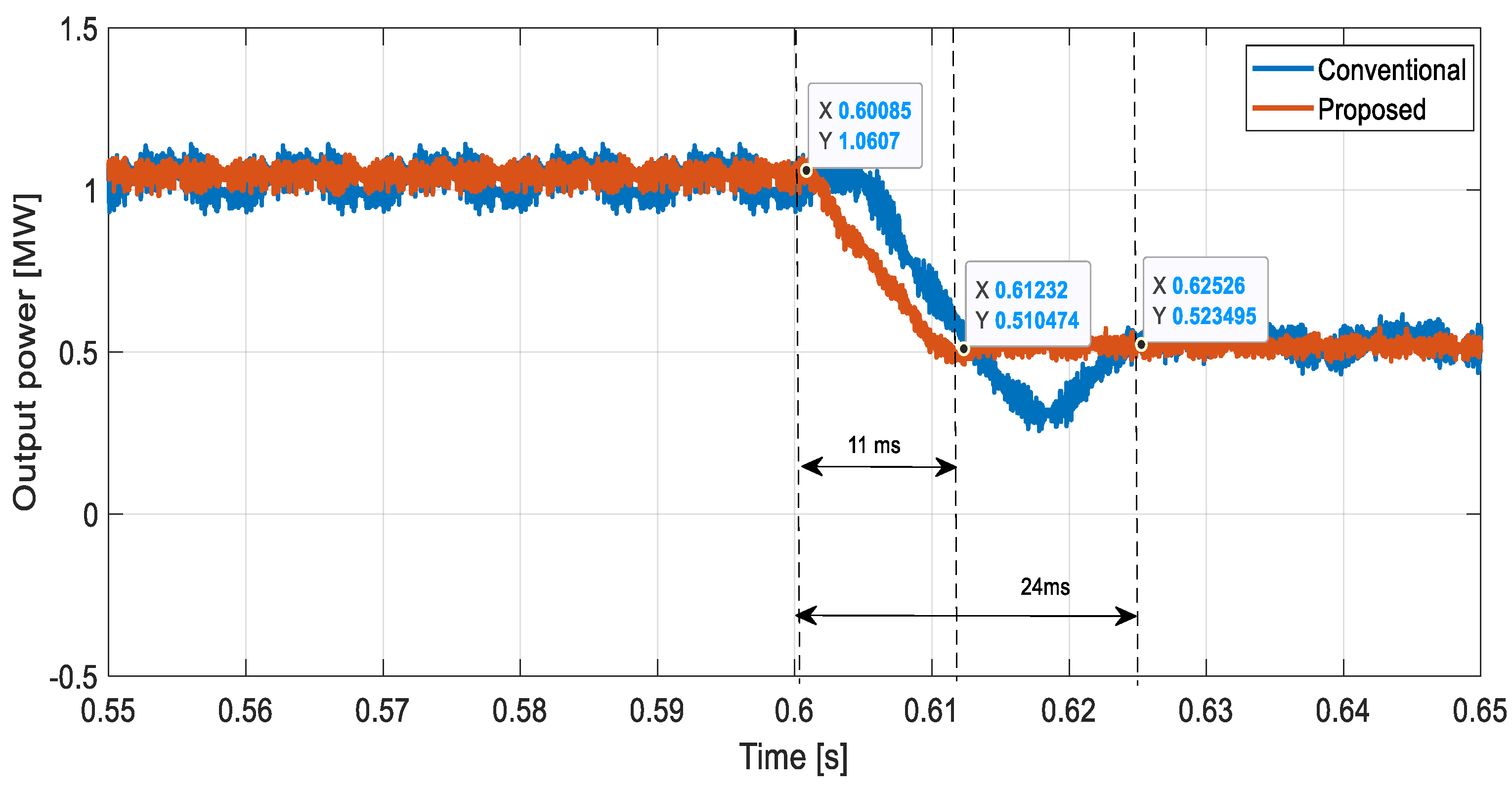
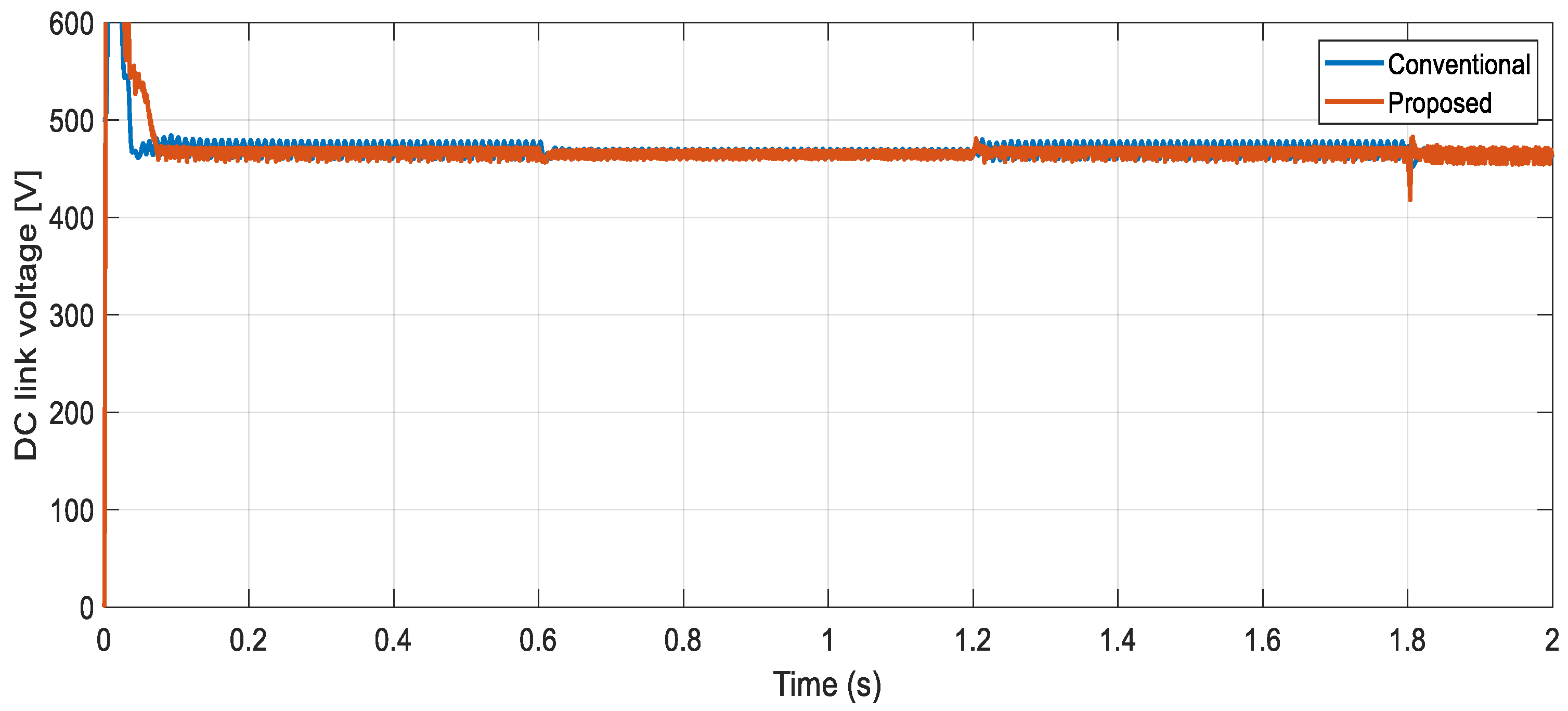
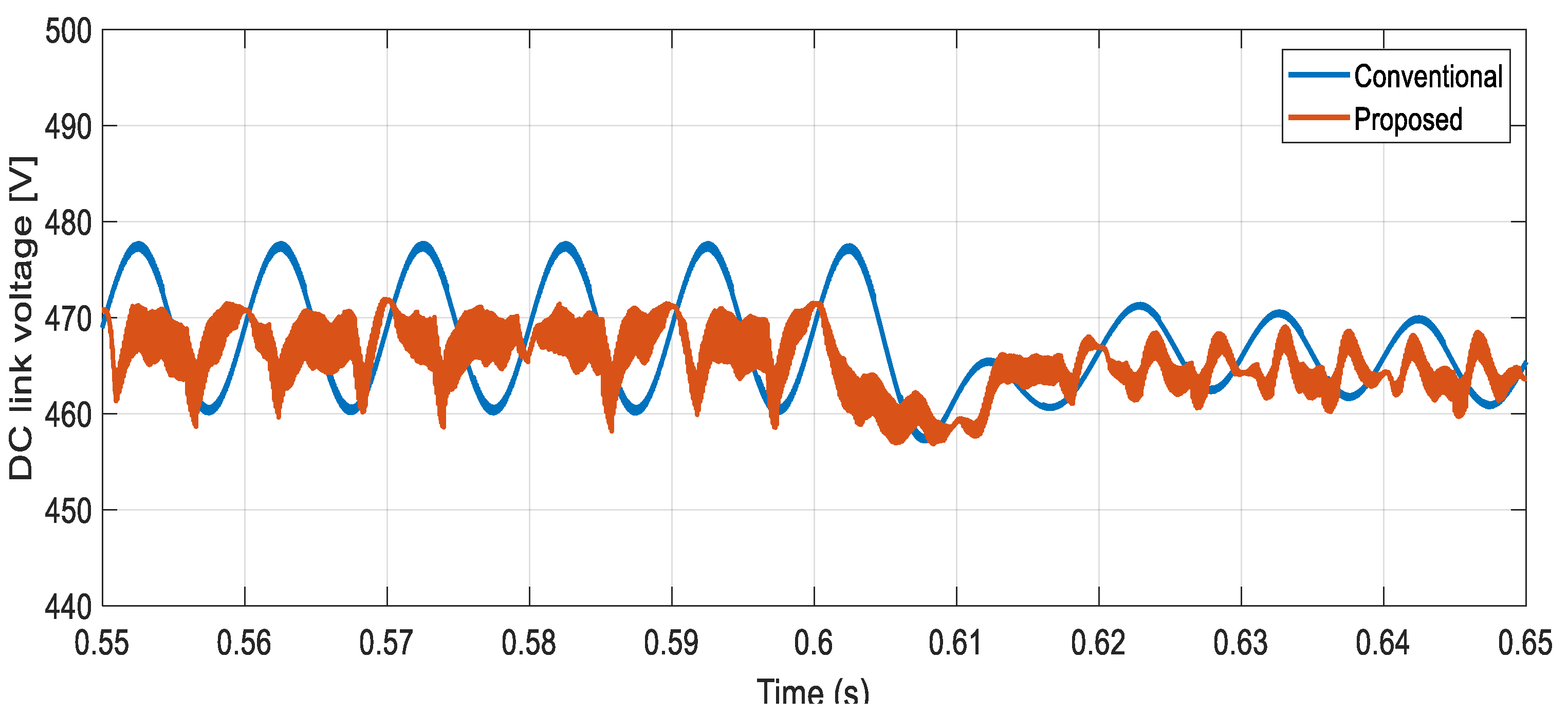
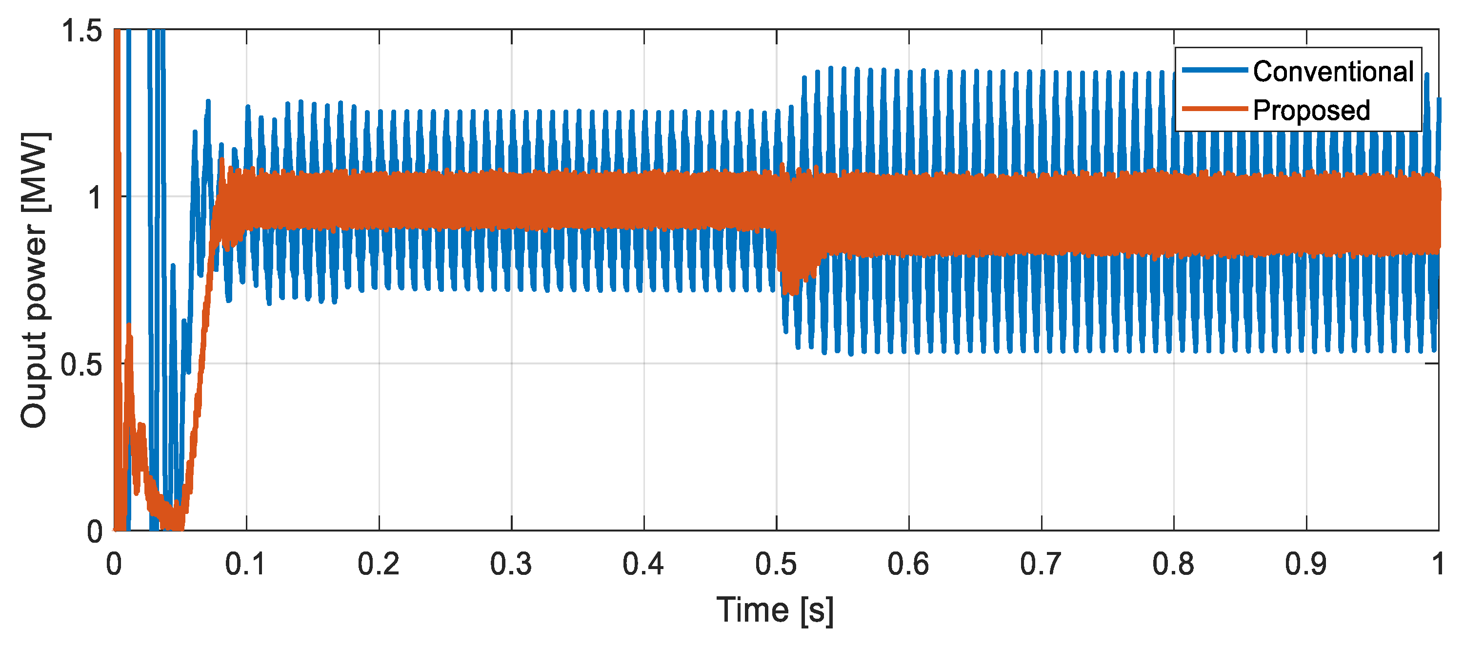
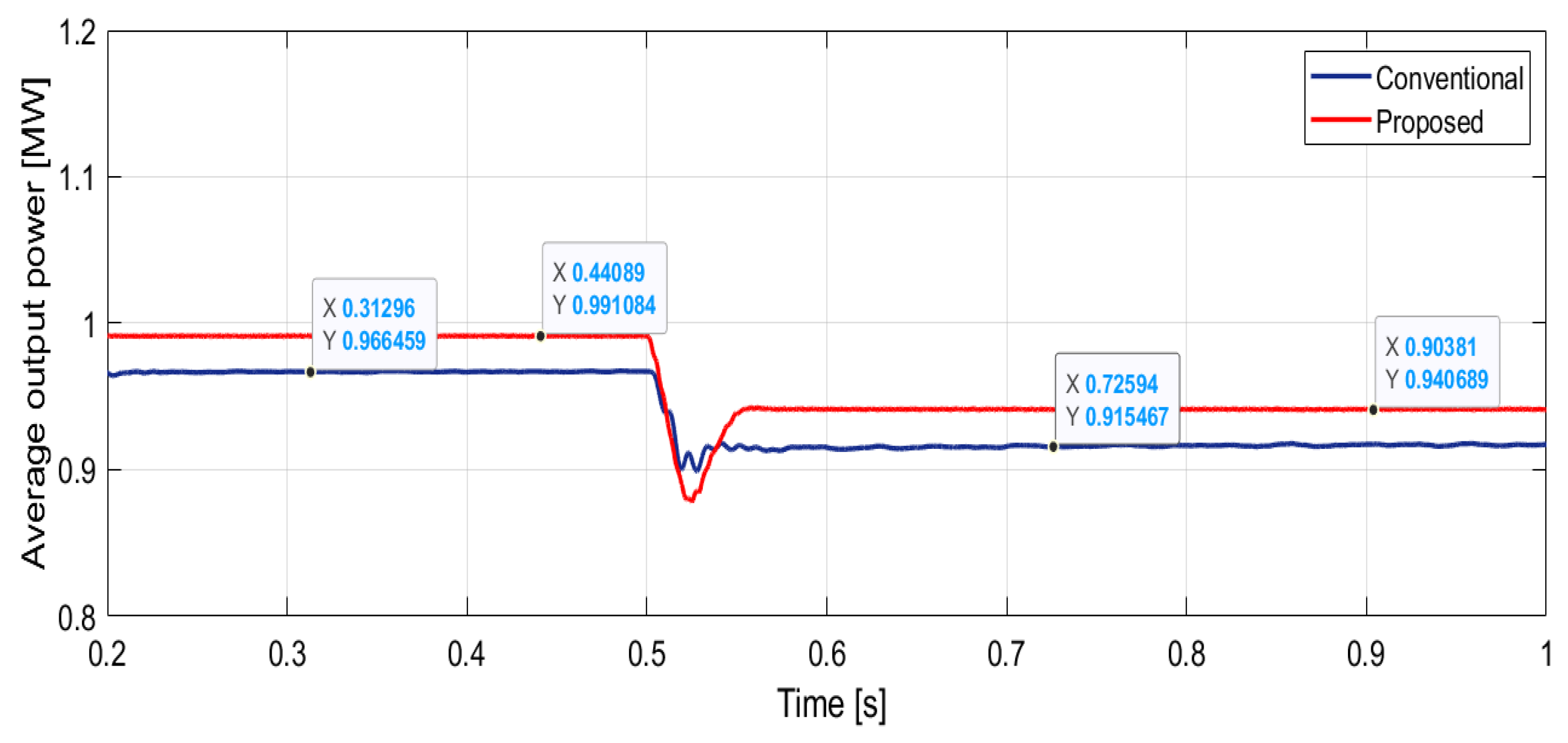
| Time response to disturbance [ms] | 11 | 22 | 2 times reduction |
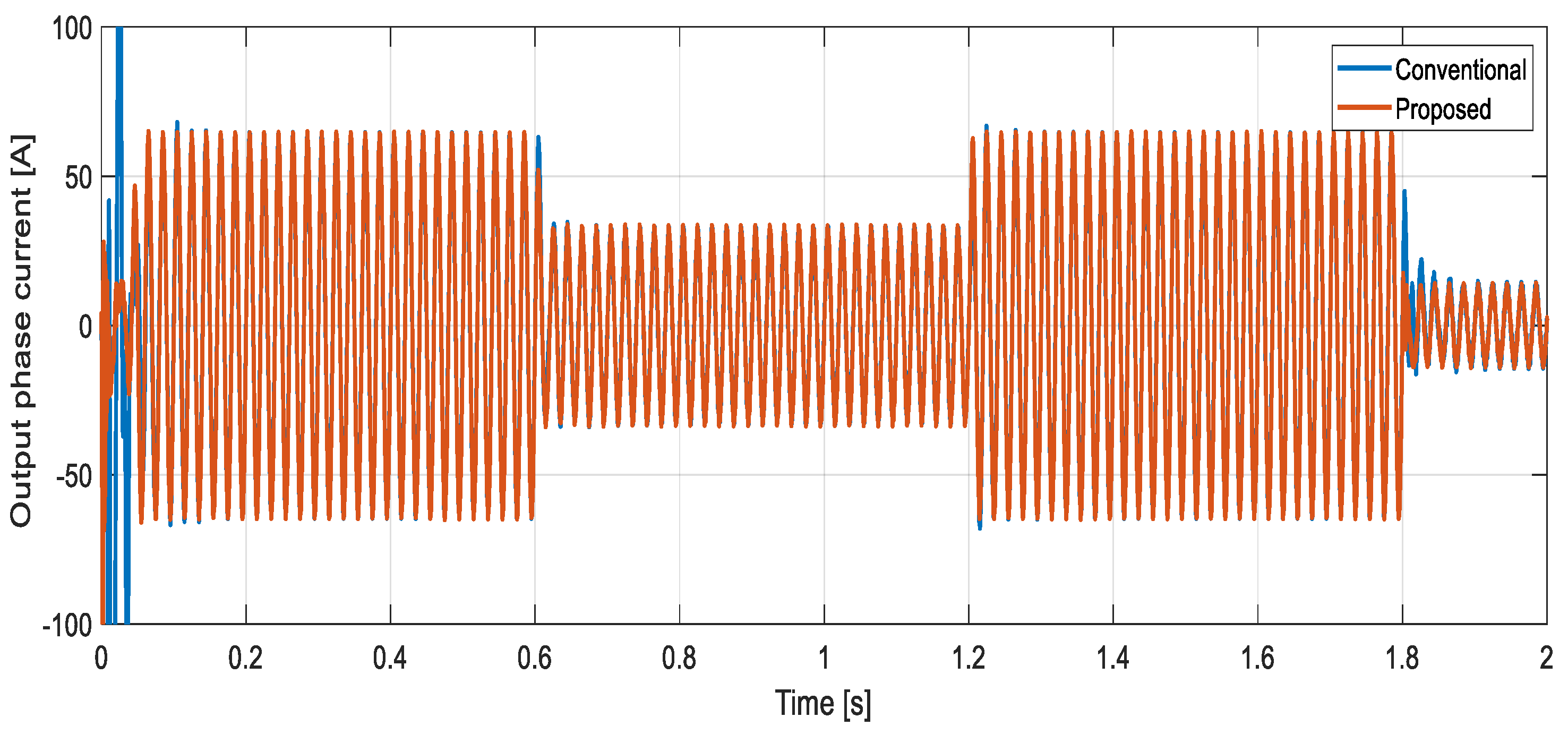
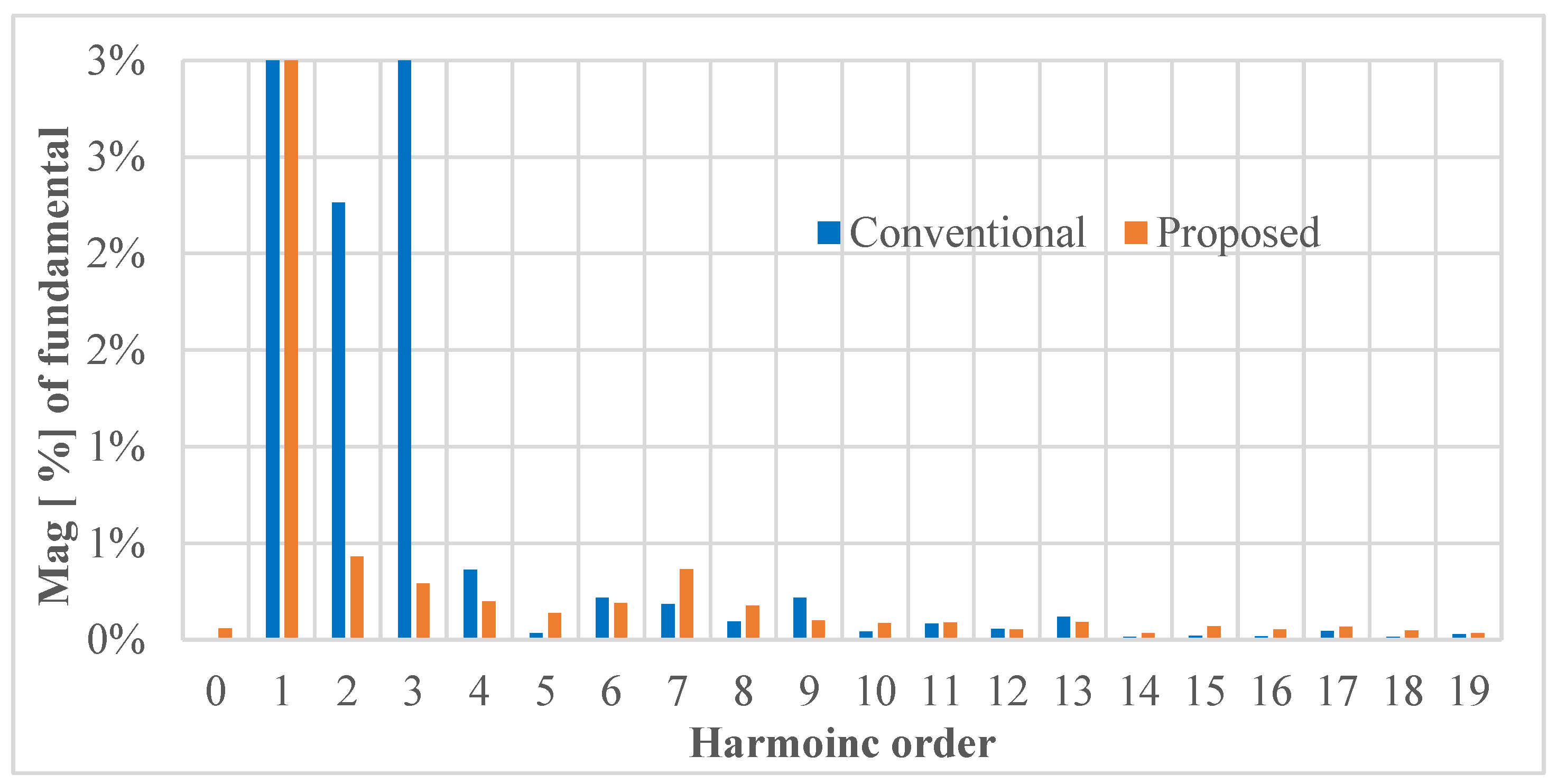
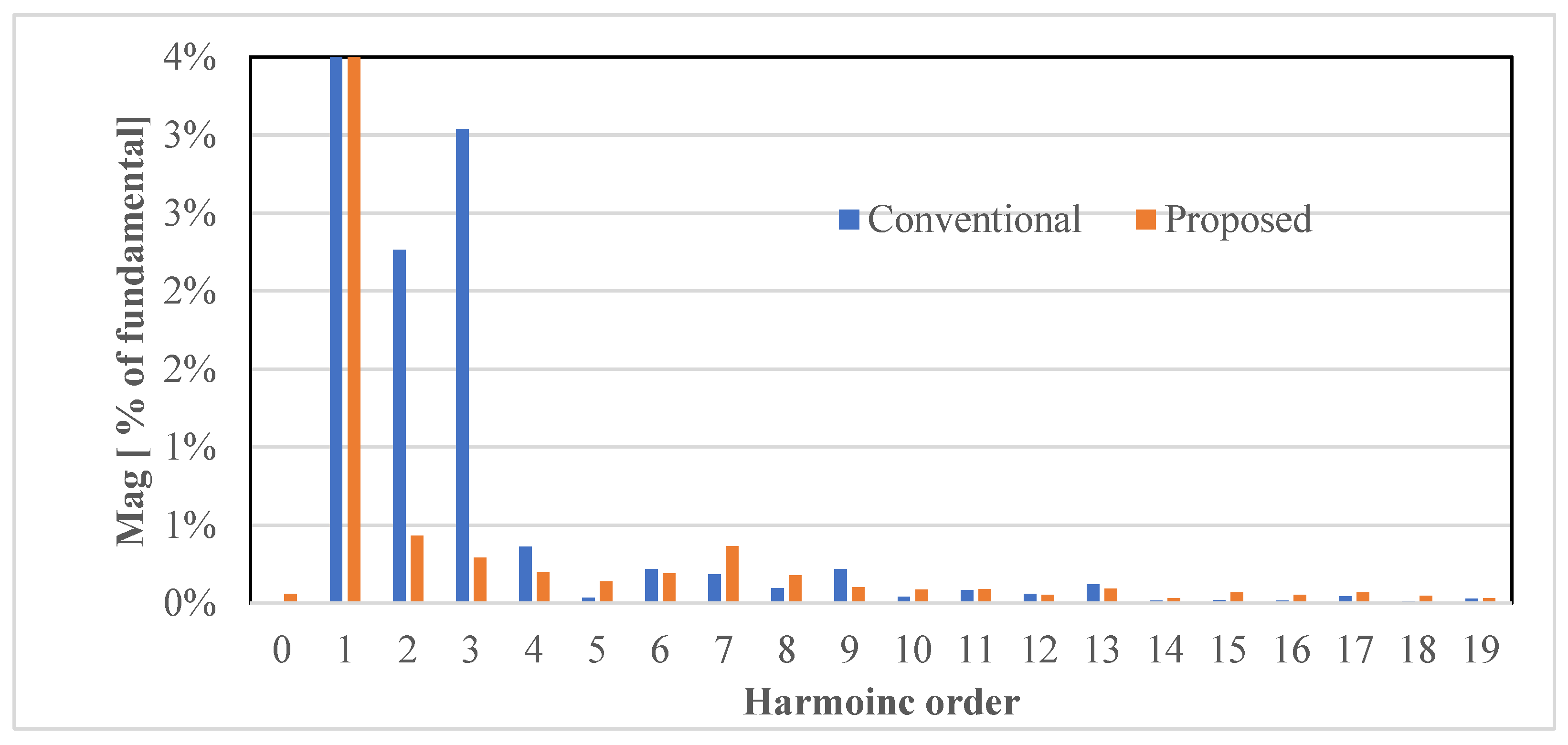
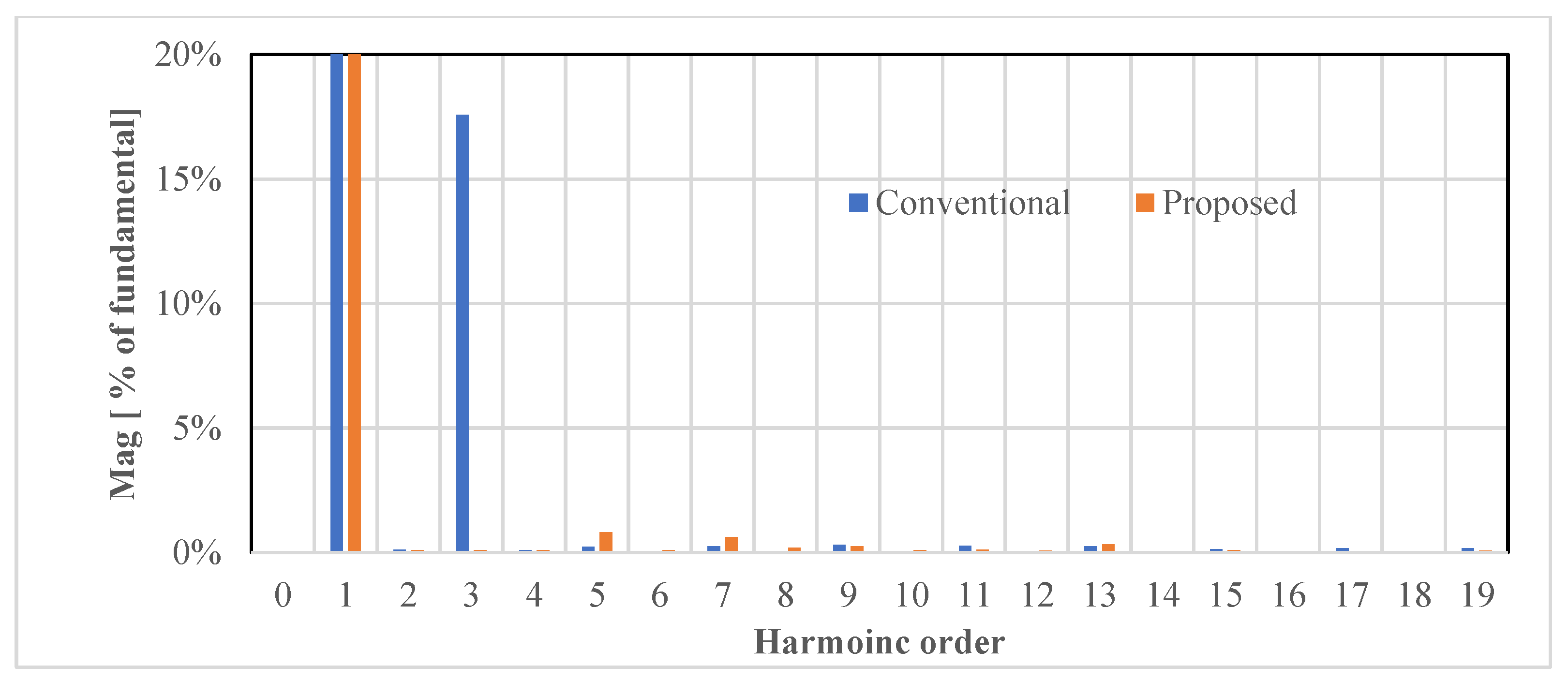
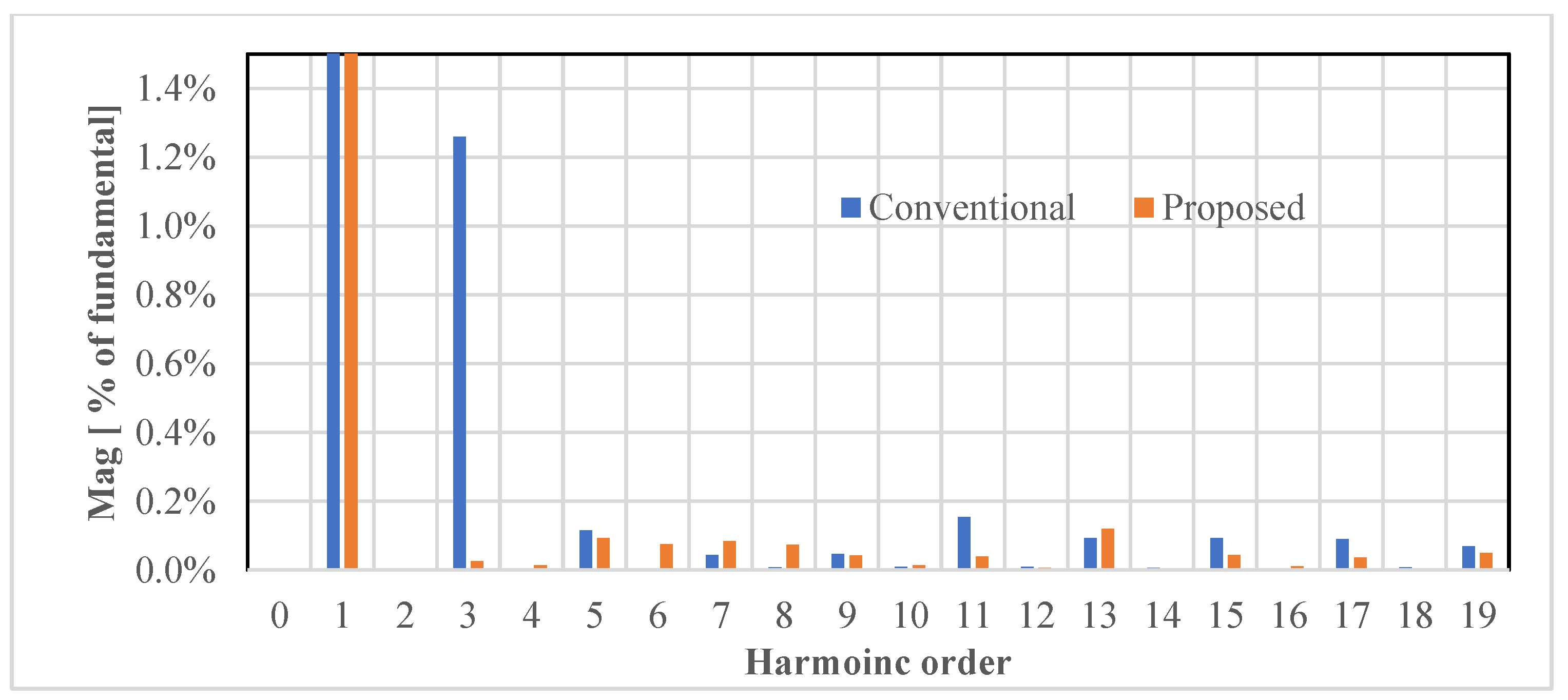
| THD for current [%] | 1.92% | 3.88% | 2 times reduction |
| THD for voltage [%] | 2.18% | 2.42% | 30% reduction |
| Item | Proposed | Conventional |
|---|---|---|
| DC/AC converter (H-bridge at the load side) | ||
| Number of MOSFETs | 288 | 288 |
| MOSFET Id | IPW60R016CM8XKSA1 | IPW60R016CM8XKSA1 |
| Price | USD 7.66 | USD 7.66 |
| Total price | USD 2206.08 | USD 2206.08 |
| DC link capacitor | ||
| Number of capacitors | 72.00 | 72.00 |
| Value | 0.12 µF | 6 F |
| Price | USD 0.26 | USD 1.81 |
| Caps Id | RSBPC1150DQ00J | C4AULBU4660M1CK |
| Caps total price | USD 19.01 | USD 130.32 |
| Rectifier (the secondary of the high-frequency transformer) | ||
| Number of diodes | 288 | |
| Voltage | 600 | |
| Current | 23.14814815 | |
| Diode Id | BYC30M-650PQ | |
| Price | USD 0.33 | |
| Total price | USD 93.60 | |
| DC/DC converter (H-bridge PV side) | ||
| Number of diodes | 72 | |
| Diode Id | VS-30ETH06-N-S1 | |
| Price/diode | USD 0.62 | |
| Number of MOSFET s | 96 | 72 |
| MOSFET ID | IPW60R016CM8XKSA1 | IPP65R110CFDXKSA2 |
| Price of MOSFET | USD 7.66 | USD 2.65 |
| Total price | USD 735.36 | USD 235.37 |
| Total cost for the whole system excluding the transformer price | USD 3054.05 | USD 2571.77 |
Disclaimer/Publisher’s Note: The statements, opinions and data contained in all publications are solely those of the individual author(s) and contributor(s) and not of MDPI and/or the editor(s). MDPI and/or the editor(s) disclaim responsibility for any injury to people or property resulting from any ideas, methods, instructions or products referred to in the content. |
© 2025 by the authors. Licensee MDPI, Basel, Switzerland. This article is an open access article distributed under the terms and conditions of the Creative Commons Attribution (CC BY) license (https://creativecommons.org/licenses/by/4.0/).
Share and Cite
Alnuman, H.; Hussain, E.; Aly, M.; Ahmed, E.M.; Alshahir, A. Cascaded H-Bridge Multilevel Converter Topology for a PV Connected to a Medium-Voltage Grid. Machines 2025, 13, 540. https://doi.org/10.3390/machines13070540
Alnuman H, Hussain E, Aly M, Ahmed EM, Alshahir A. Cascaded H-Bridge Multilevel Converter Topology for a PV Connected to a Medium-Voltage Grid. Machines. 2025; 13(7):540. https://doi.org/10.3390/machines13070540
Chicago/Turabian StyleAlnuman, Hammad, Essam Hussain, Mokhtar Aly, Emad M. Ahmed, and Ahmed Alshahir. 2025. "Cascaded H-Bridge Multilevel Converter Topology for a PV Connected to a Medium-Voltage Grid" Machines 13, no. 7: 540. https://doi.org/10.3390/machines13070540
APA StyleAlnuman, H., Hussain, E., Aly, M., Ahmed, E. M., & Alshahir, A. (2025). Cascaded H-Bridge Multilevel Converter Topology for a PV Connected to a Medium-Voltage Grid. Machines, 13(7), 540. https://doi.org/10.3390/machines13070540