Article

Deep Reinforcement Learning-Based Active Disturbance Rejection Control for Trajectory Tracking of Autonomous Ground Electric Vehicles

1
School of Mechatronic Engineering and Automation, Shanghai University, Shanghai 200072, China
2
Shanghai Key Laboratory of Intelligent Manufacturing and Robotics, Shanghai University, Shanghai 200072, China
*
Author to whom correspondence should be addressed.
Machines 2025, 13(6), 523; https://doi.org/10.3390/machines13060523
Submission received: 15 May 2025 / Revised: 7 June 2025 / Accepted: 10 June 2025 / Published: 16 June 2025

Abstract

This paper proposes an integrated control framework for improving the trajectory tracking performance of autonomous ground electric vehicles (AGEVs) under complex disturbances, including parameter uncertainties, and environmental changes. The framework integrates active disturbance rejection control (ADRC) for real-time disturbance estimation and compensation with a deep deterministic policy gradient (DDPG)-based deep reinforcement learning (DRL) algorithm for dynamic optimization of controller parameters to improve tracking accuracy and robustness. More specifically, it combines the Line of Sight (LOS) guidance rate with ADRC, proves the stability of LOS through the Lyapunov law, and designs a yaw angle controller, using the extended state observer to reduce the impact of disturbances on tracking accuracy. And the approach also addresses the nonlinear vehicle dynamic characteristics of AGEVs while mitigating internal and external disturbances by leveraging the inherent decoupling capability of ADRC and the data-driven parameter adaptation capability of DDPG. Simulations via CarSim/Simulink are carried out to validate the controller performance in serpentine and double-lane-change maneuvers. The simulation results show that the proposed framework outperforms traditional control strategies with significant improvements in lateral tracking accuracy, yaw stability, and sideslip angle suppression.

1. Introduction

In recent years, the rapid development of autonomous driving technology has made it an important part of future intelligent transportation systems. Among critical technologies for autonomous driving, path planning and trajectory tracking control are interdependent components: while path planning generates feasible trajectories (e.g., lane-change maneuvers in complex urban scenarios [1]), trajectory tracking ensures precise execution of these paths. Trajectory tracking control is pivotal for ensuring vehicle stability and safety, particularly for autonomous ground electric vehicles (AGEVs) [2,3,4,5]. It can be said that trajectory tracking control for AGEVs is crucial for the safety and stability of autonomous vehicles. This task poses the following challenges unique to AGEV dynamics: (1) multi-source disturbance coupling: internal disturbances coupled with external perturbations create nonlinear time-varying disturbance bundles that degrade model-based controllers; (2) execution–precision duality: path planners generate geometrically feasible trajectories, yet kinematic execution under disturbances demands millimeter-level tracking accuracy to avoid safety-critical deviations; (3) real-time adaptability deficit: conventional controllers lack online self-optimization capability when facing unmodeled scenarios, causing cumulative error propagation. Recently, the advances and application of machine learning have become a hot topic in scientific research and a direction of in-depth exploration. Among them, deep reinforcement learning (DRL) [6,7,8] is a cutting-edge technology that combines deep learning and reinforcement learning. It has the advantage of being able to handle high-dimensional state space and continuous action space without relying on an accurate system model, and provides a new idea for solving such complex control problems.
Existing trajectory tracking controllers, such as Linear Quadratic Regulator (LQR) [9,10] and Model Predictive Control (MPC) [11,12], often struggle to address complex perturbations, including sensor delays, parameter uncertainties, modeling inaccuracies, and external environmental disturbances. These limitations degrade tracking accuracy and robustness, especially in dynamic scenarios like high-speed maneuvers or low-friction road conditions. Specifically, LQR’s performance is highly sensitive to model accuracy and struggles with inherent nonlinearities and significant unmodeled dynamics. MPC suffers from a high computational burden that limits real-time applicability in highly dynamic scenarios, especially when complex nonlinear models are used. Furthermore, both LQR and MPC typically require extensive manual tuning for optimal performance across diverse operating conditions, and their performance degrades significantly under large, unforeseen disturbances or significant model mismatches. ADRC, through a disturbance estimation and compensation mechanism, significantly outperforms LQR and MPC in model uncertainty, nonlinear processing, and anti-disturbance capabilities [13,14,15]. This philosophy of resolving physical-layer disturbances via motion control (rather than perception-layer compensation) aligns with recent advances in quadrotor-based inspection, where speed regulation successfully eliminates image motion blur without hardware upgrades [16]. In [17], a hybrid input shaping and fuzzy active disturbance rejection control (FADRC) method is proposed for a flexible-joint robot with disturbances and uncertainties, which shows superior trajectory tracking, disturbance rejection, and robustness in position control and vibration suppression compared with the traditional controller. An adaptive control design for the trajectory tracking of a Delta robot with uncertain dynamics within an active disturbance rejection framework is presented in [18], using an adaptive least mean square-based nonparametric model representation and a simultaneous observer–identifier scheme to eliminate velocity measurements, which experimentally and numerically demonstrates better tracking accuracy and robustness than PID and non-adaptive controllers even under a five times faster reference trajectory. In [19], an extended state observer (ESO)-based ADRC scheme is implemented for the trajectory tracking of the Pendubot system by utilizing tangent linearization and differential flatness in a cascade configuration, and its accurate tracking performance is also experimentally demonstrated. Because of its low computational burden, simplified parameter tuning, and compatibility with data-driven methods, ADRC makes itself an ideal choice for controlling complex dynamic systems such as autonomous vehicles. This capability aligns with emerging efforts to enhance perception robustness through motion constraints—exemplified by bounded UDE control for quadrotors that safeguards SLAM integrity via regulated attitude angles [20], which has great experimental applications.
Deep reinforcement learning is a combination of reinforcement learning (RL) and deep learning (DL), which aims to learn the optimal decision-making strategy through the interaction between the agent and the environment [21,22,23]. Deep deterministic policy gradient (DDPG) is a deep reinforcement learning algorithm designed for continuous action space. It can solve continuous action space problems (such as robot control) and output deterministic actions based on the Actor–Critic framework [24,25,26]. Although many newer and more robust algorithms have emerged, such as Soft Actor–Critic (SAC) and twin delayed deep deterministic policy gradient (TD3), DDPG is still the best choice considering the following three key factors related to vehicle stability: (1) its deterministic policy output eliminates action sampling variance that could induce hazardous oscillatory behavior in safety-critical systems; (2) it demonstrates robustness in comparable real-time control applications including motor drives and power converters with stability guarantees; (3) it has reduced computational complexity relative to maximum entropy approaches (e.g., SAC), enabling deterministic response within autonomous vehicles’ hard real-time constraints while maintaining sufficient exploration through parameter space noise injection. In [27], a DRL-enhanced ADRC framework is introduced for the flux weakening control of aerospace motors. The AI-driven ADRC parameter optimization is pioneered through interface modules and DDPG to solve complex and weakly sensitive parameters. Its convergence, robustness, and performance, which are superior to those of traditional methods, are verified through simulations and experiments. In [28], a DDPG-optimized ADRC approach for IoT-based DC-DC buck converters in smart grids is introduced and validated in a real-time CoAP/Wi-Fi test with network degradation, outperforming the state-of-the-art approaches in terms of robustness and adaptability. Notably, beyond parameter tuning, RL can directly generate compensatory control signals, as demonstrated in quadrotor fault tolerance where PPO maintained stability during rotor failures [29]. Policy iteration-based ADRC is proposed in [30] for uncertain nonlinear systems. It integrates partial control inputs and RL agents, adaptively adjusts degree weights through iterative policy refinement, and achieves real-time output tracking without the knowledge of system dynamics, relative degrees, or external disturbances; meanwhile, semi-global stability is ensured through Lyapunov analysis and verified through simulation and permanent magnet synchronous motor experiments. The integration of ADRC with DDPG addresses the critical limitations of both traditional controllers and standalone ADRC for AGEV trajectory tracking. While ADRC provides a robust framework for real-time estimation and rejection of “lumped” disturbances, its effectiveness is often contingent on manual tuning of key parameters (e.g., observer bandwidth, controller gains), which can be suboptimal under highly variable driving conditions. DDPG, operating as a data-driven meta-controller, directly tackles this parameter tuning challenge. It dynamically learns and adapts the ADRC parameters online based on the observed vehicle states and tracking performance, optimizing for robustness and accuracy across diverse and unforeseen scenarios. This synergy leverages ADRC’s core strength in disturbance handling while overcoming its tuning limitations via DRL’s model-free optimization capability, offering a solution that is both highly robust and self-adaptive. To overcome these challenges, this paper proposes a novel control framework that integrates ADRC with DDPG reinforcement learning, aiming to enhance both disturbance rejection and adaptive parameter tuning capabilities for the trajectory tracking of AGEVs, and the core innovation lies in combining ADRC’s inherent ability to estimate and compensate for lumped disturbances with DDPG’s data-driven optimization.
In this paper, a trajectory tracking controller of AGEVs is designed based on the ADRC framework. ADRC can treat unknown coupling information as disturbances, and estimate and eliminate disturbances. This study uses the DDPG algorithm to dynamically adjust the controller parameters to solve the challenging problem of parameter adjustment of the ADRC and further improve the tracking accuracy and robustness of the controller. Finally, the proposed method is verified on a joint simulation platform to prove its effectiveness.

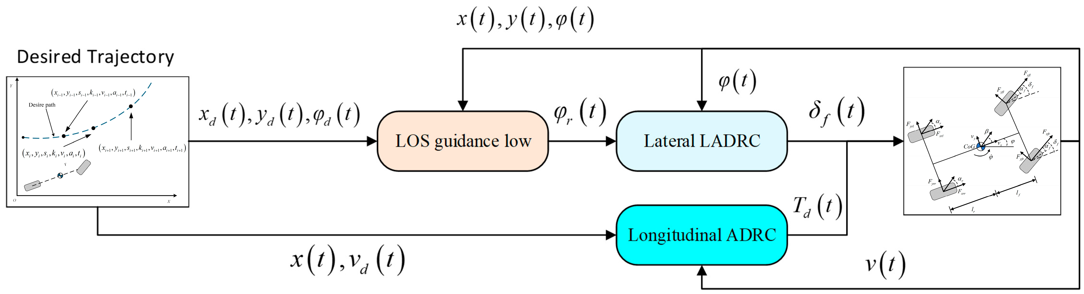
2. Design of Trajectory Tracking Control System

x e ( t ) y e ( t ) = cos φ d ( t ) sin φ d ( t ) sin φ d ( t ) cos φ d ( t ) T x ( t ) x d ( t ) y ( t ) y d ( t )
Since distributed drive electric vehicles (DDEVs) exhibit underactuated and strongly nonlinear dynamic characteristics, the front wheel steering angle and longitudinal velocity need to be coordinated to ensure that the longitudinal position, lateral position, and heading angle reach the desired values. That is, the tracking errors x e t and y e t must asymptotically converge to zero. Therefore, a robust control system and guidance law must be designed to enable the DDEV to track arbitrary reference trajectories from any initial state while maintaining sufficient disturbance rejection capability against both internal uncertainties and external environmental perturbations.

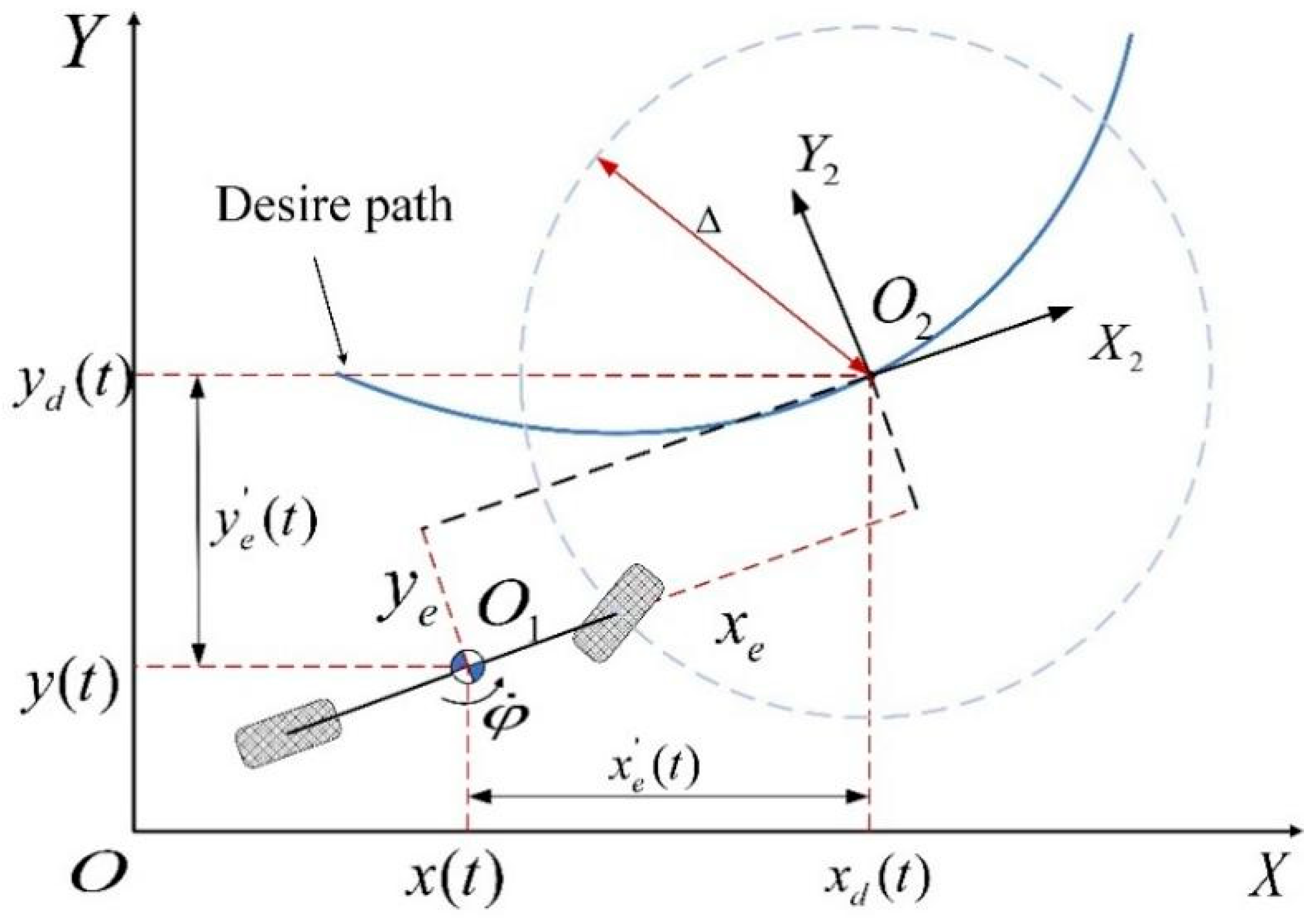
2.1. Design of Trajectory Tracking Guidance Law

From the DDEV model equations, it is evident that the DDEV model exhibits coupling characteristics. Furthermore, during actual driving, parameters such as vehicle dynamics, motion states, and external disturbances undergo real-time variations, leading to system uncertainties. Under these conditions, it is challenging to parse out the required control quantity to achieve a good tracking effect. To address these issues, this study integrates the Line of Sight (LOS) guidance law with active disturbance rejection control (ADRC) for trajectory tracking control.
Figure 1 illustrates the geometric representation of the LOS guidance law, where Δ denotes the look-ahead distance. The proposed LOS guidance law is formulated as follows:
φ r ( t ) = φ d ( t ) arctan ( y e ( t ) Δ ) β ( t ) v x ( t ) = ( v x d ( t ) k x e ( t ) ) y e ( t ) 2 + Δ 2 Δ
where φ r and v x represent the reference values for the heading angle and longitudinal velocity during trajectory tracking, respectively, and k is a positive constant ( k > 0 ). The desired heading angle   φ d and desired longitudinal velocity v x d are defined as
φ d ( t ) = arctan ( y d ( t ) y d ( t 1 ) x d ( t ) x d ( t 1 ) ) v x d ( t ) = x ˙ d ( t ) cos ( φ d ( t ) ) + y ˙ d ( t ) sin ( φ d ( t ) )
where (xd (t − 1), yd (t − 1)) denotes the desired vehicle position at the previous time step. The stability of the proposed LOS guidance law is subsequently proven using Lyapunov theory.
Theorem 1. 
Assume the heading angle φ(t) and longitudinal velocity u(t) can track their reference values φr(t) and vx(t) in real time, i.e.,
φ t = φ r t ,   u t = v x t
Then, the trajectory tracking errors x e t and y e t asymptotically converge to zero.
Proof. 
Construct the Lyapunov function as
V = 1 2 x e 2 + 1 2 y e 2
The derivative of the trajectory tracking errors is
x ˙ e = x ˙ cos φ d + y ˙ sin φ d x ˙ d cos φ d + y ˙ d sin φ d φ ˙ d x x d sin φ d y y d cos φ d = u cos φ φ d + β v x d + φ ˙ d y e
y ˙ e = u sin φ φ d + β + φ ˙ d x e
Differentiating the Lyapunov function V:
V ˙ = x e x ˙ e + y e y ˙ e = x e u cos φ φ d + β v x d + φ ˙ d y e + y e u sin φ φ d x e φ ˙ d
Substituting φ r from Equation (2) into Equation (7):
V ˙ = x e u cos arctan y e Δ v x d + φ ˙ d y e + y e u cos arctan y e Δ φ ˙ d x e = u x e Δ Δ 2 + y e 2 y e Δ Δ 2 + y e 2 x e v x d
Define
u = v x d k x e Δ 2 + y e 2 Δ
It follows that
V ˙ = u y e 2 y e 2 + Δ 2 k x e 2
This study focuses solely on forward-motion tracking scenarios, thus constraining the longitudinal velocity (vx) to non-negative values. Since k > 0 and u ≥ 0, it follows that V ˙ ≤ 0, thereby proving the asymptotic convergence of the tracking errors.

2.2. Yaw Angle Controller Design

The extended state observer (ESO) can estimate system states and external disturbances while inherently possessing decoupling characteristics. Therefore, this paper employs active disturbance rejection control (ADRC) to regulate the front wheel steering angle   δ f and longitudinal velocity v x . The schematic diagram of the control system is illustrated in Figure 2.
To design the yaw angle controller, the relationship between the yaw angle φ and the front wheel steering angle δf must first be established. According to Newton’s second law, the dynamic Equation (11) for the vehicle’s yaw motion is given by
I z φ ¨ = l f F f x r + F f x l sin δ f + W f 2 F f x r F f x l cos δ f + l f F f y r + F f y l cos δ f + W f 2 F f y l F f y r cos δ f + l r F r y r + F r y l + W r 2 F r x r + F r x l
By treating the direct yaw moment control as an external disturbance to the yaw angle controller, the system can be simplified to a second-order model:
φ ¨ = 1 I z l f N α f δ f v y + l f φ ˙ v x + f 1
where f1 represents the total disturbance in the trajectory tracking control system, including external environmental disturbances, internal parameter uncertainties, and disturbances induced by active yaw moments. To mitigate the impact of disturbances on tracking accuracy, a third-order linear extended state observer (LESO) is designed. Defining the system states as x 1 = y 1 , x 2 = y ˙ 1 , x 3 = f 1 , the state-space representation of the system is
x ˙ 1 = x 2 x ˙ 2 = x 3 + b 1 δ f x ˙ 3 = f ˙
By extending the state-space model, the LESO is designed as
x ^ ˙ 1 = x ^ 2 + β 1 y 1 x ^ 1 x ^ ˙ 2 = x ^ 3 + β 2 y 1 x ^ 1 + b 1 δ f x ^ ˙ 3 = β 3 y 1 x ^ 1
where β1, β2, β3 are observer gains, and x ^ ˙ 1 , x ^ ˙ 2 , x ^ ˙ 3 denote the observed state values.
To reduce the number of LESO tuning parameters, a bandwidth parameterization method is adopted. Based on the yaw motion characteristics, the observer gains are tuned using this method to achieve accurate estimation and compensation of disturbances. For Equation (14), by selecting an appropriate observer gain, the observed value can track the upper state value:
x ^ 1 x 1 , x ^ 2 x 2 , x ^ 3 f x 1 , x 2
The closed-loop characteristic polynomial of the LESO is configured with all poles placed at ω o , yielding
s + ω o 3 = s 3 + β 1 s 2 + β 2 s + β 3
Expanding this polynomial gives
β 1 = 3 ω 0 , β 2 = 3 ω o 2 , β 3 = 3 ω o 3
By adjusting ωo, the LESO parameters can be optimized such that x ^ 3 f 1 , enabling disturbance compensation in the control law:
δ f = k p x ^ 1 k d x ^ 2 x ^ 3 b 1
where kp and kd are the controller parameters.
The bandwidth of the ESO determines its tracking speed for total disturbances. The bandwidth parameterization method configures the closed-loop system’s dynamic characteristics by setting the ESO bandwidth parameters, eliminating reliance on precise model knowledge. ADRC does not require accurate model parameters; instead, it treats both model uncertainties and external disturbances as part of the total disturbance. The ESO dynamically estimates this total disturbance and provides real-time compensation through the control law, thereby removing model dependency.
Regardless of whether disturbances are low-frequency or high-frequency, the ESO can effectively estimate and compensate them provided its bandwidth is sufficiently high—though this requires careful trade-offs with noise sensitivity.

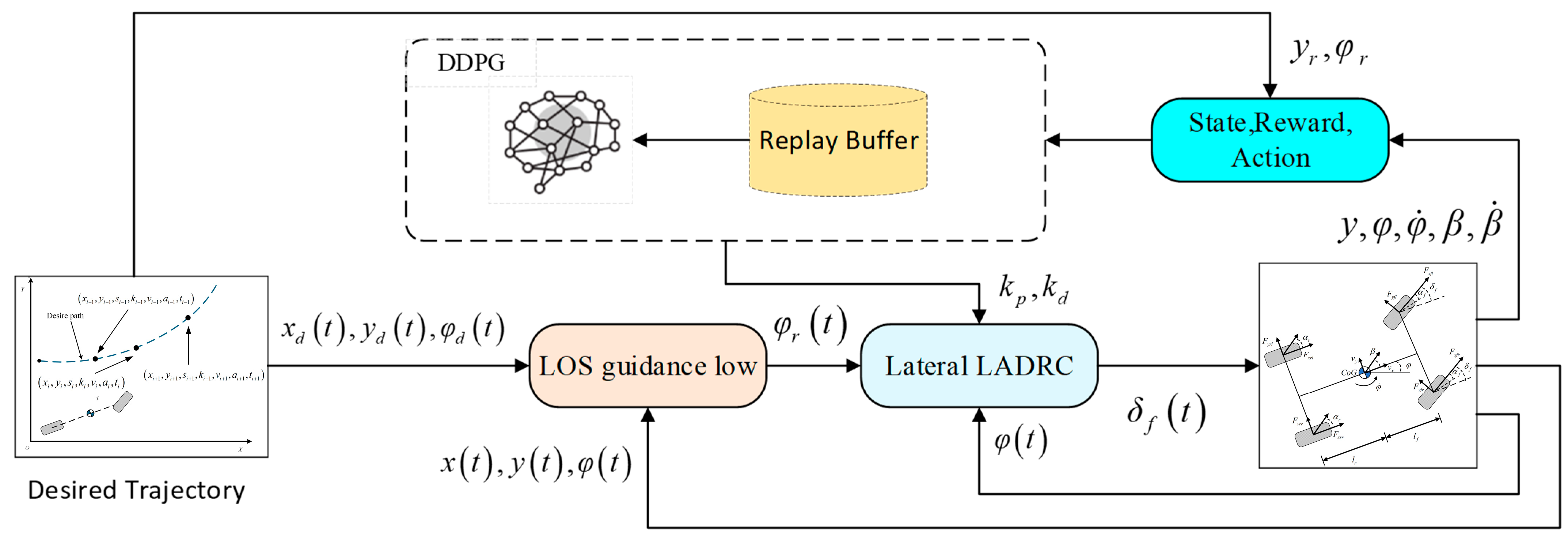
3. DRL-Based ADRC Strategy Design

3.1. Fundamental Concepts of Reinforcement Learning

Reinforcement learning (RL), as a critical paradigm of machine learning, is characterized by an autonomous learning mechanism where an agent interacts dynamically with its environment. In this framework, the agent explores actions through trial-and-error to receive environmental feedback (rewards or penalties) and adjusts its behavioral policy to maximize long-term cumulative returns. Unlike supervised learning (which relies on labeled datasets) and unsupervised learning (which focuses on intrinsic data patterns), RL does not depend on pre-annotated static datasets. Instead, its training data originates from real-time environmental interactions, forming an incremental learning mechanism based on immediate feedback—a defining feature of RL.
At the technical integration level, RL can be combined with deep learning to form deep reinforcement learning (DRL). By leveraging the powerful nonlinear representation capabilities of deep neural networks, DRL effectively handles high-dimensional state spaces and optimizes decision-making strategies in complex scenarios. This integration aligns with the common goal of the three major branches of machine learning (supervised learning, unsupervised learning, and reinforcement learning)—extracting value from data—but RL uniquely emphasizes the cultivation of autonomous decision-making abilities in dynamic environments.
Environment state representation (S): As a digital expression of the system’s current environmental characteristics, the state is encoded through a multidimensional vector or a specific symbol system. This parameter reflects the immediate characteristics of the agent’s environment and can be divided into two modes: fully observable (complete access to environmental information) and partially observable (inference based on limited perceptual inputs). The reasonable design of the state space directly affects the performance and complexity of the algorithm.
Action space (A): This refers to the set of executable actions available to the agent in a given state, including discrete actions (e.g., steering commands) and continuous actions (e.g., velocity adjustments). Action selection influences state transitions and policy optimization, it requires a balance between task requirements and computational efficiency.
Immediate reward mechanism (R): This is a scalar feedback signal that quantifies the quality of a state–action pair. The reward function serves as a navigational guide for system optimization, steering the agent toward optimal policies through trial-and-error. To balance immediate and long-term rewards, a discount factor γ is introduced to model cumulative returns:
G t = R t + 1 + γ R t + 2 + γ 2 R t + 3 + = k = 0 γ k R t + k + 1   ( 0 γ 1 )
State transition dynamics: The state transition dynamics are described by a probabilistic model, P ( s s , a ) , which quantifies the likelihood of transitioning to state s after taking action a in state s. In model-free RL, this function is estimated through empirical sampling.
Agent–environment interaction: This refers to a closed-loop system comprising a perception module (environment) and a decision-making unit (agent). The agent continuously observes the environment, generates control commands via a policy network, and iteratively optimizes its strategy using reward feedback.
Policy function (π): This defines the mapping from states to actions, categorized into deterministic policy (direct mapping) and stochastic policy (a probability distribution):
π ( a | s ) = P ( A t = a | S t = s )
State value function (V(s)): This function evaluates the expected long-term return of being in state s:
V π ( s ) = E π G t | S t = s
Action value function (Q (s, a)): This function evaluates the expected return of taking action a in state s:
Q π ( s , a ) = E π G t | S t = s , A t = a
These functions are governed by the Bellman equations, which establish iterative relationships for value estimation.
Optimization objective: The goal is to solve for the optimal value functions V s and Q s , a , which derive the optimal policy π to maximize cumulative rewards:
V * ( s ) = max a R ( s , a ) + γ s P s s a V * ( s )
Q * ( s , a ) = R ( s , a ) + γ s P s s a max a Q * ( s , a )
The RL framework integrates perception, decision-making, and feedback into a cohesive architecture for autonomous learning. The dynamic interplay between these components underpins the mathematical foundation of RL algorithms, with the Bellman optimality principle serving as the theoretical core for policy optimization.
Value Iteration: The value function is directly iterated and updated through the Bellman optimality equation, and it finally converges to the optimal value function. First, all state values V(s) = 0 are initialized. Process (25) is repeatedly executed while updating the value function until convergence:
V k + 1 ( s ) = max a R ( s , a ) + γ s P ( s | s , a ) V k ( s )
The optimal policy is extracted from the converged value function (26). This method requires no explicit policy maintenance and converges faster with smaller discount factors (γ).
π * ( s ) = arg max a A R ( s , a ) + γ s S P ( s | s , a ) V * ( s )
Policy Iteration: Policy iteration alternates between policy evaluation and policy improvement. The following policy evaluation (27) and policy improvement process (28) are repeated until the policy is stable. Policy iteration has the advantage of faster convergence than value iteration, but requires the storage of complete policies and value functions, and is suitable for scenarios where the exact model is known.
V k + 1 π ( s ) = a π ( a | s ) R ( s , a ) + γ s P ( s | s , a ) V k π ( s )
π new ( s ) = arg max a R ( s , a ) + γ s P ( s | s , a ) V π ( s )
Q-Learning: The action value function Q s , a is updated by sampling experience, without knowing the transition probability P. First, Q s , a is initialized to an arbitrary value. In each interaction, action a is selected according to state s. The reward r and the next state s are observed, and the Q value (29) is updated. This method is applicable to unknown environments, but it is limited by the dimensions of the state and action space, and requires tuning of the learning rate and exploration rate.
Q ( s , a ) Q ( s , a ) + α r + γ max a Q ( s , a ) Q ( s , a )
Monte Carlo Methods: The value function is estimated by averaging the returns of the complete trajectory. First, a trajectory is generated ( s 0 ,   a 0 ,   r 1 ,   s 1 , a 1 , ,   s T ). The return of each state s t is calculated:
G t = k = 0 T t γ k r t + k + 1
The value function is updated by averaging returns:
V ( s ) 1 N total ( s ) i = 1 N total ( s ) G t ( i )
V ( s t ) V ( s t ) + α G t V ( s t )
Monte Carlo methods provide unbiased estimates but suffer from high variance and require episodic tasks.

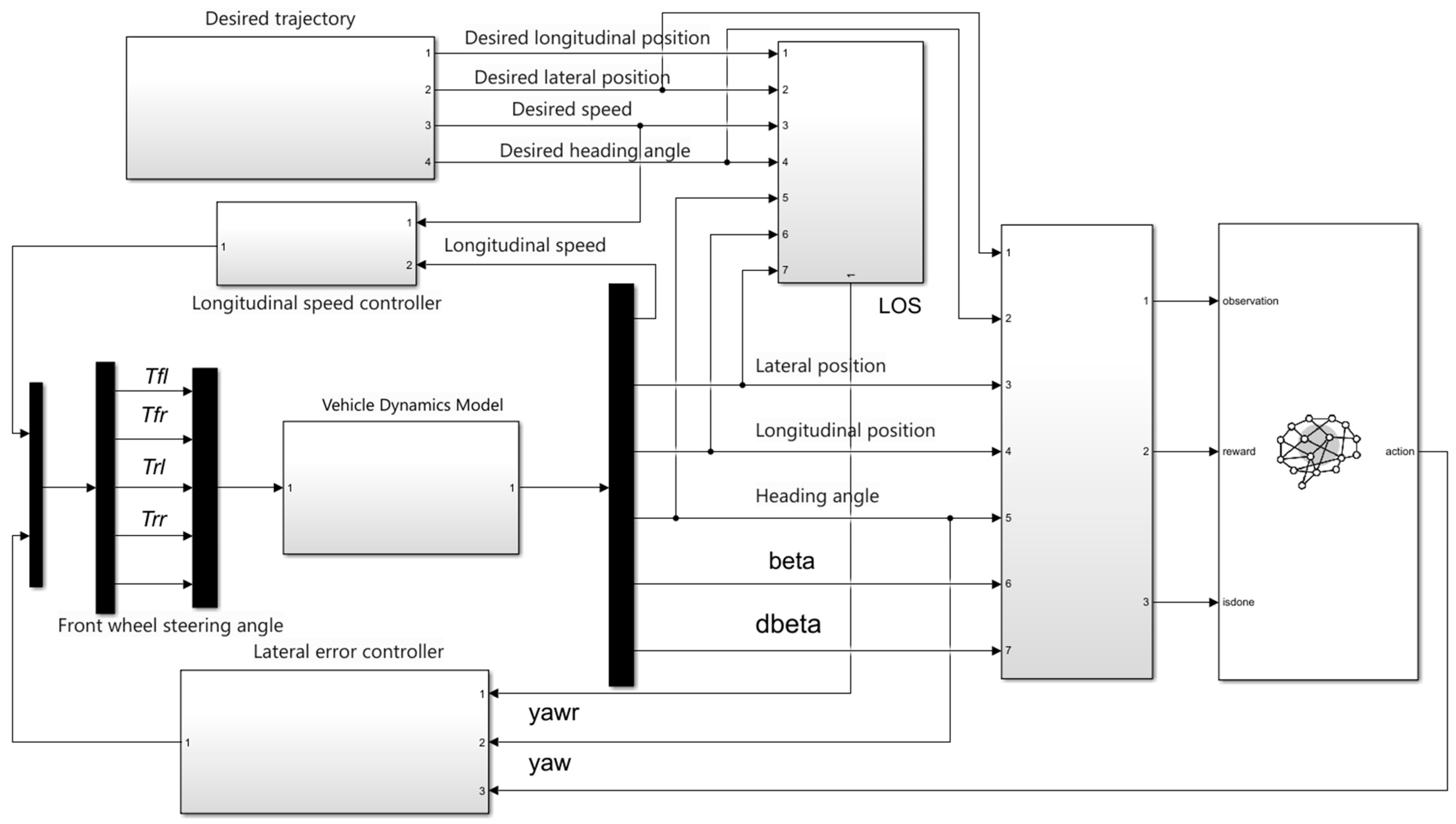
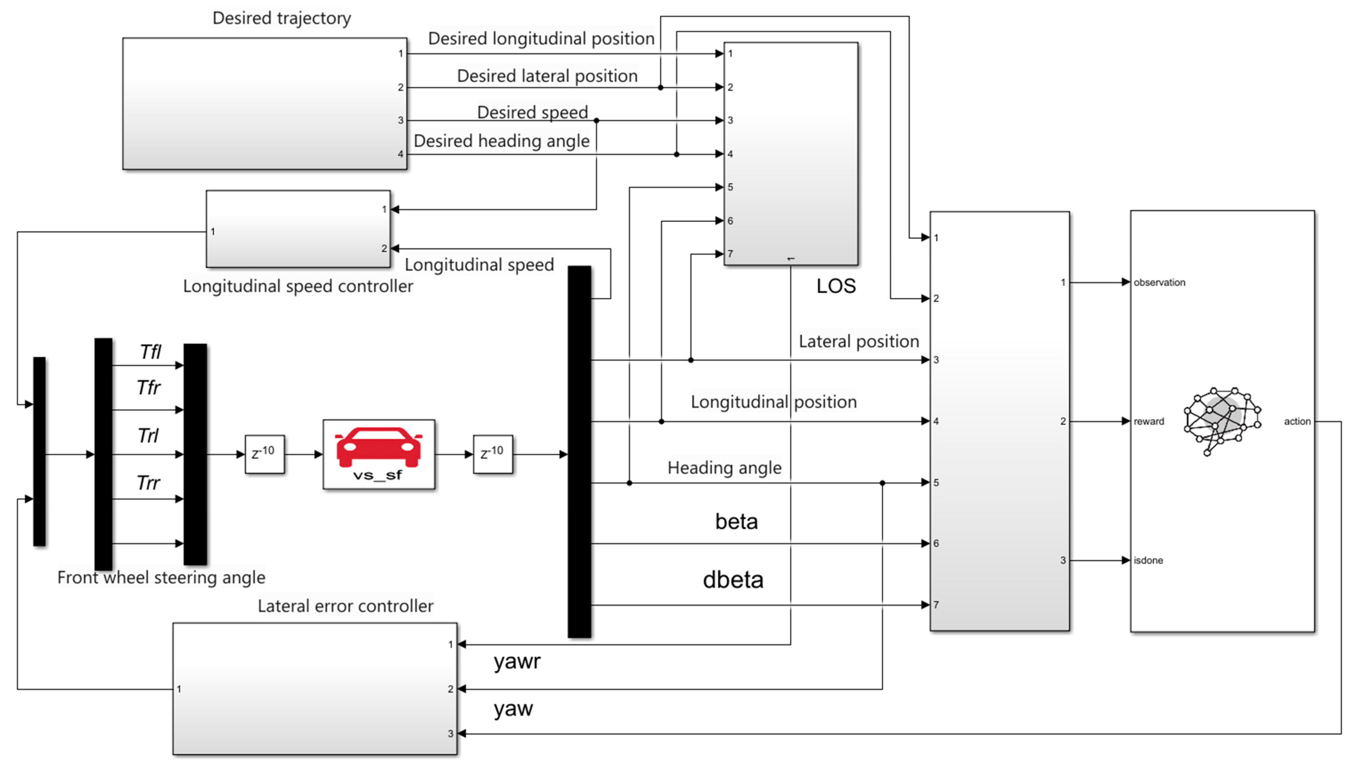
3.2. DRL-Based ADRC Trajectory Tracking System
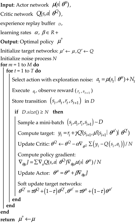
To address the controller gain optimization challenges caused by the multi-variable, strongly coupled dynamics of AGEVs, this section proposes a novel data-driven ADRC parameter tuning architecture. The framework leverages the deep deterministic policy gradient (DDPG) algorithm to establish a “state–action” mapping mechanism. Through deep reinforcement learning, the system dynamically generates optimal gain combinations and injects them into the vehicle’s lateral dynamics model to achieve high-precision trajectory tracking. This end-to-end adaptive parameter adjustment framework effectively bypasses the rigid coupling constraints between controller gains and system states inherent in traditional methods.
Figure 3 illustrates the DDPG-ADRC control architecture. The agent interacts with the AGEV’s lateral dynamics environment in real time, dynamically adjusting control strategy parameters via DRL to maximize cumulative rewards. The architecture takes state observations—such as lateral position error, yaw angle error, and vehicle state parameters—as inputs. The output layer provides optimal parameter combinations, including proportional gain (kp), derivative gain (kd), and observer bandwidth (ωo). This data-driven parameter optimization mechanism ensures robust tracking performance across diverse operating conditions.
Figure 4 outlines the DDPG algorithm’s workflow, which adopts a four-network topology comprising dual copies of the policy evaluation network (Critic) and the behavior decision network (Actor). Key components include the following:
Experience replay buffer: This component stores state transition tuples ( s t , a t , r t , s t + 1 ) for batch training.
Delayed update mechanism: This component maintains asynchronous parameter updates between online and target networks, inheriting weight freezing strategies from Deep Q-Networks (DQN).
Actor–Critic (AC) framework: This component integrates dual-path optimization, where the Critic network evaluates the expected cumulative reward Q ( s , a θ Q ) for state–action pairs s , a .
The Critic network receives state values and Actor-generated actions as inputs, outputting Q value estimates:
Q s , a = E R c | s t = s , a t = a
In the deep reinforcement learning framework, the policy network generates control commands by dynamically interpreting environmental state vectors. Its parameter optimization process is detailed in Algorithm 1. A comparative analysis reveals that while both the Soft Actor–Critic (SAC) and deep deterministic policy gradient (DDPG) algorithms adopt a dual-network architecture (policy network and value evaluation network), they exhibit fundamental differences in decision-making mechanisms. DDPG employs a deterministic policy gradient method, directly outputting precise action values a t = μ ( s t θ μ ) , where exploration relies on externally injected Ornstein–Uhlenbeck (OU) noise. SAC, based on maximum entropy reinforcement learning theory, constructs a stochastic policy function to output action probability distributions a t π ( s t ; θ π ) , actively regulating exploration intensity through entropy regularization. This mechanistic divergence endows SAC with superior policy robustness in complex dynamic environments, while it preserves DDPG’s engineering applicability advantages in deterministic control scenarios.
Algorithm 1: DDPG
Machines 13 00523 i001
The state input of the deep reinforcement learning agent in this section is an array consisting of the actual lateral position, desired lateral position, actual yaw angle, desired yaw angle, yaw angular velocity, and sideslip angle of the center of mass, as shown in Table 1.
The action space is defined by the parameters requiring dynamic adjustment in the controller. The agent outputs the optimal parameter set { a 1 , a 2 A a 1 = k p , a 2 = k d }, where kp (proportional gain) and kd (derivative gain) significantly impact trajectory tracking accuracy. These parameters are computed based on Equation (18) and serve as inputs to the vehicle dynamics model in CarSim.
The reward function is designed to minimize tracking errors and stabilize vehicle dynamics:
r t = β s i g n β β ˙ s i g n β ˙ s 1 t s 2 t s i g n s 1 t s 3 t s i g n s 2 t s 4 t
where
s 1 t = y r t y t , s 2 t = φ r t φ t s 3 t = y ˙ r t y ˙ t , s 3 t = φ ˙ r t φ ˙ t
The primary optimization objectives of the reward function are to minimize the lateral tracking error and the yaw angle error. To enhance trajectory tracking precision, absolute error terms for both lateral deviation and yaw angle deviation are incorporated. Additionally, error differential terms are introduced to ensure the errors exhibit a convergence trend toward zero. The sideslip angle not only acts as a critical indicator of vehicle stability but also indirectly influences passenger comfort. A larger sideslip angle is typically accompanied by significant body roll and lateral oscillations, causing passengers to perceive unstable lateral forces. Therefore, incorporating a sideslip-angle-related term into the reward function can enhance both vehicle stability and ride comfort. Additionally, oscillations in the front wheel steering angle can amplify the sideslip angle. Introducing sideslip-angle-related terms into the control framework can help mitigate such steering oscillations, thereby improving the smoothness of control outputs.
Table 1 shows the proxy parameters used to train the DDPG controller. Since it does not involve the processing of images and high-dimensional information, there is no need to use a convolutional neural network, so this paper chooses a fully connected network for design. This paper adopts a fully connected neural network with three hidden layers as the Actor network. The input layer receives the lateral trajectory tracking errors ( s 1 , s 2 , s 3 , s 4 ) and vehicle states ( β , β ˙ ). In the Actor neural network, which has three fully connected hidden layers with 50, 40, and 30 neurons, respectively, the activation function is the Relu function. The output action is A, and the activation function is the Tanh function. A feature extraction channel that decreases layer by layer is formed. The output layer generates a two-dimensional action space (kp, kd).
The Critic network adopts a dual-channel fully connected structure. The input end simultaneously receives the state vector and the action parameters (kp, kd) generated by the Actor network, and realizes state–action joint feature extraction through three hidden layers. The dual-channel fully connected layers have 200, 150, and 100 neurons. The final output layer uses a linear activation function to generate Q value estimates. This design enhances the evaluation accuracy of state–action pairs through deep feature cross-talk, providing a stable gradient update direction for the Actor network.

4. Simulation and Analysis

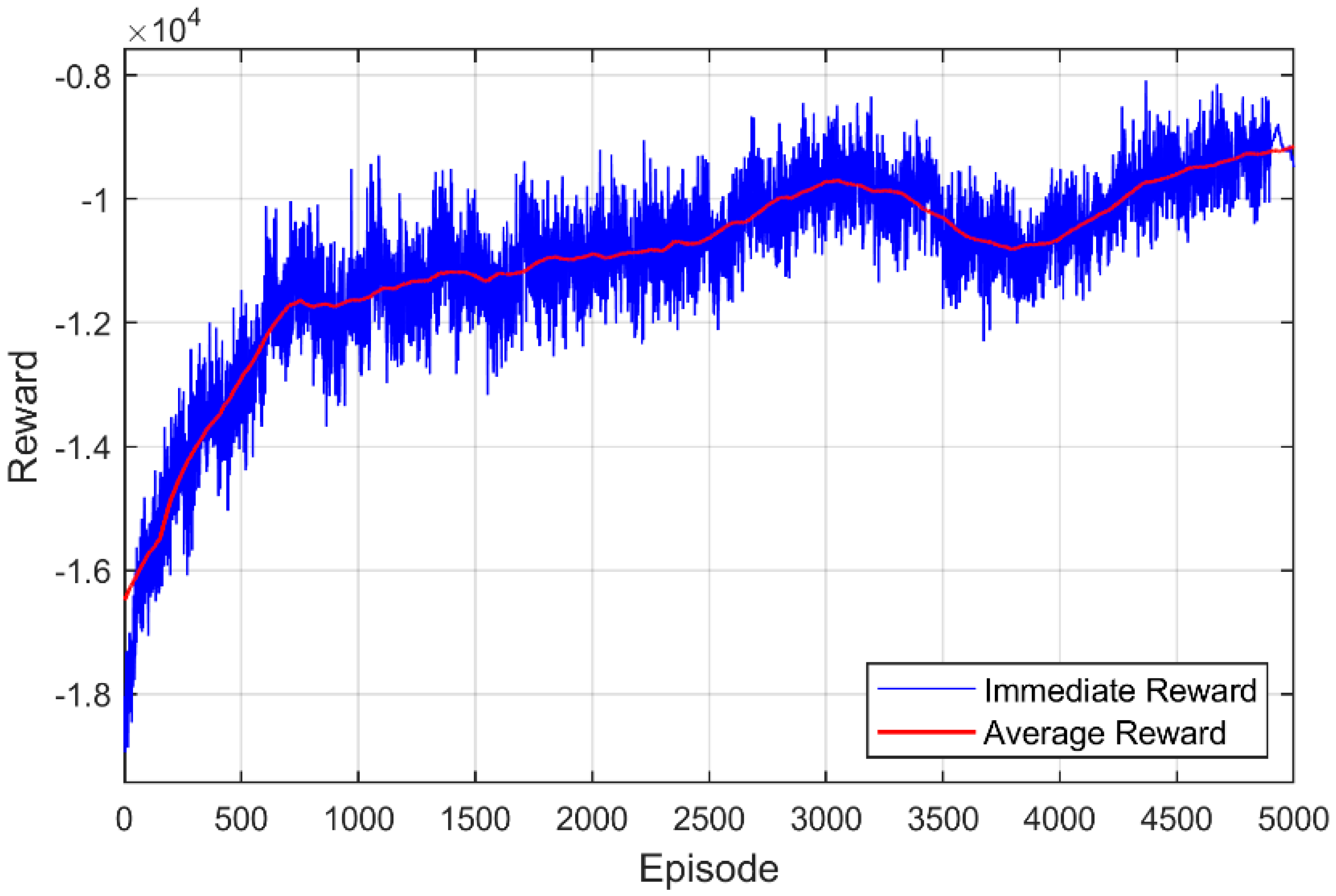
4.1. Simulation and Training Environment

Carsim 6.0 software can provide a high-precision vehicle dynamics model, but the deep reinforcement learning agent built into Matlab/Simulink 2019 software needs to use the fast restart function during training. Carsim software does not support the fast restart of the Simulink model at the beginning of each round of training. To address this incompatibility, two solutions are proposed: (a) modify the MATLAB/Simulink package code to deactivate the DRL toolkit’s rapid restart feature, or (b) replace CarSim with a 7-degree-of-freedom (7-DOF) vehicle dynamics model during training.
Since both CarSim and disabling rapid restart significantly increase computational time, prolonging single-episode training, the 7-DOF model is adopted for training. CarSim is later reintroduced for high-precision validation in simulation experiments. The DRL training environment based on the 7-DOF model is illustrated in Figure 5.
To simulate realistic trajectory tracking scenarios, quintic polynomial trajectories are randomly generated at the start of each training episode. To prevent overly smooth trajectories or sharp turns (which destabilize reward values and hinder training), the constraints defined in Table 2 are applied.
With the agent parameters and training environment configured as per Table 1, the DDPG training results are shown in Figure 6. The blue curve represents per-episode rewards, while the red curve denotes the moving average. It can be seen that with the increase in the number of test rounds, the average value of the reward increases and tends to converge after 4500 rounds. The data shows that the reward value of the reinforcement learning strategy shows a stable dynamic convergence characteristic during the training process. The training curve shows that the cumulative return of the agent presents two significant characteristics—that is, there is obvious fluctuation in the strategy exploration stage, and there is continuous positive correlation growth in the parameter optimization stage—and finally reaches a dynamic equilibrium state. This convergence behavior validates the algorithm’s exploration efficacy in continuous action spaces and confirms that the policy network progressively approaches optimal controller parameters through gradient updates.
Figure 7 outlines the simulation workflow, where the 7-DOF model is replaced with CarSim for final validation. The training duration per episode is set to 30 s. The random trajectory generator is substituted with a reference trajectory module, and tracking performance is evaluated under diverse operating conditions. Key vehicle and controller parameters are listed in Table 3. The tire cornering stiffness values are derived from the curve fitting of the tire force characteristics in CarSim.

4.2. Serpentine Maneuver

In the simulation of the serpentine maneuver, the vehicle speed vx is set to 126 km/h and the road adhesion coefficient µ is set to 0.6. It can be seen from the trajectory tracking result (Figure 8a) that all three controllers can track the expected trajectory, but from the yaw angle tracking (Figure 8b), it can be seen that DDPG-ADRC has the most stable tracking effect on the yaw angle, and the tracking yaw angle of LQR fluctuates greatly.
The results of the tracking error (Figure 9 and Figure 10) are further analyzed. From the lateral error (Figure 9), it can be clearly seen that the DDPG-ADRC controller has a smaller lateral error, and the smallest tracking error at both the beginning and end of the serpentine trajectory, and the convergence speed is significantly better than that of the MPC and LQR controllers. The maximum lateral error of DDPG-ADRC is 0.02 m, which is 50% higher than the maximum lateral error of 0.04 m of LADRC. At the same time, it can be seen that LQR is greatly affected by the medium road adhesion coefficient, and there are large fluctuations at the beginning and end of the serpentine trajectory, which reduces the stability of the vehicle. From the yaw angle error (Figure 10), it can be seen that the DDPG-ADRC controller has a better tracking effect on the desired yaw angle than the LADRC and MPC controllers. The tracking effect of the LQR controller in the middle of the serpentine trajectory is close to that of the DDPG-ADRC controller and the MPC controller, but it has large fluctuations at the beginning of the serpentine trajectory.
By analyzing the center-of-mass slip angle result (Figure 11a) during the tracking process, it can be concluded that DDPG-ADRC has better stability, and its maximum center-of-mass slip angle is only 3.6, which is 47%, 38%, and 36% higher than the maximum center-of-mass slip angles of 6.8°, 5.8°, and 5.6° of LADRC, MPC, and LQR, respectively. From the center-of-mass slip angle phase plane (Figure 11b), it can be found that the stability of the DDPG-ADRC controller is significantly better than that of the LADRC and MPC controllers, and the LQR controller is seriously unstable. From the control variable front wheel angle result (Figure 12a), it can be seen that the LQR controller fluctuates greatly, which is consistent with the previous tracking results and vehicle stability parameters. The LESO disturbance estimation results are shown in Figure 12b. The results of MAE, RMSE, and MSE under serpentine conditions are shown in Table 4.

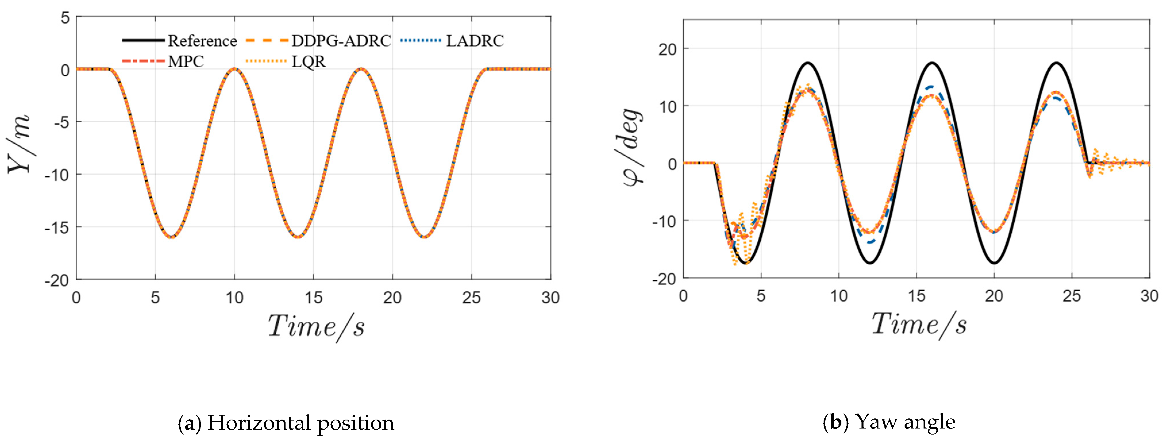
4.3. Double-Lane-Change Maneuver

In the simulation of the double-lane-change maneuver, the vehicle speed vx is set to 126 km/h and the road adhesion coefficient µ is set to 0.5. From the trajectory tracking result (Figure 13a), it can be seen that both DDPG-ADRC and MPC can track the desired trajectory. The LQR controller can track the desired trajectory in the double-lane-change stage, but the convergence speed is too slow in the final stable stage. From the yaw angle tracking (Figure 13b), it can also be seen that DDPG-ADRC and MPC can converge quickly and stabilize.
The results of the lateral and yaw angle errors (Figure 14 and Figure 15) are shown above. From the lateral error (Figure 14), it can be clearly seen that the DDPG-ADRC controller has a smaller lateral error. It has the smallest tracking error at the beginning and end of the double-lane-change trajectory. The maximum lateral error of DDPG-ADRC is 0.091 m, which is 6% and 31% higher than the maximum lateral errors of LADRC and MPC of 0.097 m and 0.132 m, respectively. At the same time, it can be seen that MPC and LQR are greatly affected under medium road adhesion coefficients, whereby they fluctuate greatly in the overtaking stage, and LQR converges slowly at the end of overtaking. From the yaw angle error (Figure 15), it can be seen that the DDPG-ADRC controller is slightly better than the LADRC and MPC controllers in tracking the desired yaw angle. The maximum yaw angle error of DDPG-ADRC is 15.2, which is 7% and 15% higher than the maximum yaw angle errors of LADRC and MPC of 16.5 and 17.8°, respectively.
Analyzing the center-of-mass slip angle result (Figure 16a) during tracking, it can be concluded that DDPG-ADRC has better stability, and its maximum center-of-mass slip angle is 14.8°, which is 7%, 11%, and 14% higher than the maximum center-of-mass slip angles of LADRC, MPC, and LQR of 15.9°, 16.7°, and 17.3°, respectively. From the phase plane diagram of the sideslip angle at the center of mass (Figure 16b), it can be found that the stability of the DDPG-ADRC controller is significantly better than that of the LADRC, MPC, and LQR controllers. From the control variable front wheel angle result (Figure 17a), it can be seen that the LQR controller has large fluctuations, which is consistent with the previous tracking results and vehicle stability parameters. The LESO disturbance estimation results are shown in Figure 17b. The results of MAE, RMSE, and MSE under the double-lane-change condition are shown in Table 5.
The comprehensive simulation results show that the DDPG-ADRC controller exhibits better tracking accuracy and vehicle stability under serpentine and double-lane-change conditions. Compared with the LQR controller, it significantly reduces fluctuations and avoids instability problems. It is superior to the MPC and LADRC controllers in indicators such as lateral error, yaw error, and center-of-mass sideslip angle. In contrast, LQR is sensitive to disturbances and has poor stability, MPC lacks real-time performance and has a slow response, and LADRC has limited suppression capabilities. With the synergistic advantages of reinforcement learning and anti-disturbance control, DDPG-ADRC demonstrates stronger nonlinear modeling capabilities and robustness, verifying its comprehensive control performance advantages under complex dynamic conditions.
While the proposed method has been validated on a joint simulation platform (7-DOF model with CarSim co-simulation), future work will address current limitations through two critical phases: (1) Hardware-in-the-Loop (HIL) validation using automotive-grade ECUs to evaluate real-time performance under stochastic disturbances, and (2) physical deployment with scaled robotic prototypes or vehicle testbeds incorporating real-world sensor data to improve the training process of the DDPG agent and evaluate its generalization ability and stability in the presence of unknown driving situations or environmental factors (e.g., rain or hills).

5. Conclusions

This study proposes a trajectory tracking disturbance rejection control method based on deep reinforcement learning for the trajectory tracking control problem of AGEVs. The trajectory tracking controller is designed by combining the active disturbance rejection controller framework and the deep deterministic policy gradient algorithm. Through the ADRC framework, the controller can estimate and eliminate internal and external disturbances in the system, while the DDPG algorithm is used to dynamically adjust the controller parameters, optimize the gain combination, and improve the accuracy and robustness of trajectory tracking. In the specific design of the trajectory tracking control system, this paper combines the LOS guidance rate with ADRC, proves the stability of LOS through the Lyapunov law, and designs a yaw angle controller, using the extended state observer to reduce the impact of disturbances on tracking accuracy. Compared to LADRC, MPC, and LQR, the proposed framework achieved a 50% reduction in the maximum lateral tracking error; a 47% improvement in sideslip angle stability; and a 46.71% lower RMSE in the lateral error. The DDPG-ADRC controller exhibits a smaller lateral error, a more stable yaw angle tracking effect, and better vehicle stability, effectively improving the accuracy and disturbance rejection performance of trajectory tracking. The ADRC-DDPG controller’s decoupled architecture enables plug-and-play integration with mainstream autonomous stacks, and with ADRC’s low computational burden and DDPG’s offline-trained policy network, the system meets automotive-grade hard real-time requirements. These enable real-time deployment and integration into existing autonomous vehicle systems. The proposed method has significant advantages in improving the trajectory tracking control performance of AGEVs. Since this study employs DDPG to tune ADRC parameters, the control outputs are primarily computed by ADRC. Thus, the computational latency of DDPG has negligible impact on control calculations. In simulations, the DDPG algorithm operates at 200 ms intervals, while control outputs are updated every 20 ms—i.e., ten control cycles occur per DDPG update. This provides a scalable solution for autonomous driving systems, and it is also expected to further improve the safety and stability of autonomous driving vehicles in practical applications. Future research will focus on two critical extensions: (1) fixed-time convergence enhancement: inspired by accelerated disturbance rejection strategies in power systems, we will explore fixed-time stable ADRC designs; (2) distributed multi-vehicle coordination: building upon fully distributed frameworks, we will extend the controller to multi-AGEV formations, as in the fully distributed approach [31]. The proposed method provides a scalable solution for autonomous driving systems and is expected to significantly improve the safety and stability of AGEVs in practical applications.

Author Contributions

Conceptualization, X.J., H.L., Y.T., J.L. (Jianning Lu), J.L. (Jianbo Lv) and N.V.O.I.; supervision, X.J.; conception and design, X.J. and H.L.; collection and assembly of data, X.J., H.L., Y.T., J.L. (Jianning Lu), J.L. (Jianbo Lv) and N.V.O.I.; manuscript writing, X.J., H.L., Y.T., J.L. (Jianning Lu), J.L. (Jianbo Lv) and N.V.O.I.; funding, X.J. All authors have read and agreed to the published version of the manuscript.

Funding

This work was supported by the Key Research and Development Program of China Yangtze River Delta (Grant No. 2023CSJGG0900).

Data Availability Statement

Data are contained within the article.

Conflicts of Interest

The authors declare that there are no conflicts of interest.

References

  1. Skačkauskas, P.; Karpenko, M.; Prentkovskis, O. Design and Implementation of a Hybrid Path Planning Approach for Autonomous Lane Change Manoeuvre. Int. J. Automot. Technol. 2024, 25, 83–95. [Google Scholar] [CrossRef]
  2. Coppola, A.; Lui, D.G.; Petrillo, A.; Santini, S. Eco-Driving Control Architecture for Platoons of Uncertain Heterogeneous Nonlinear Connected Autonomous Electric Vehicles. IEEE Trans. Intell. Transp. Syst. 2022, 23, 24220–24234. [Google Scholar] [CrossRef]
  3. Wang, F.; Shen, T.; Zhao, M.; Ren, Y.; Lu, Y.; Feng, B. Lane-Change Trajectory Planning and Control Based on Stability Region for Distributed Drive Electric Vehicle. IEEE Trans. Veh. Technol. 2024, 73, 504–521. [Google Scholar] [CrossRef]
  4. Liu, C.; Liu, H.; Han, L.; Wang, W.; Guo, C. Multi-Level Coordinated Yaw Stability Control Based on Sliding Mode Predictive Control for Distributed Drive Electric Vehicles Under Extreme Conditions. IEEE Trans. Veh. Technol. 2023, 72, 280–296. [Google Scholar] [CrossRef]
  5. Jin, X.; Wang, Q.; Yan, Z.; Yang, H.; Yin, G. Integrated robust control of path following and lateral stability for autonomous in-wheel-motor-driven electric vehicles. Proc. Inst. Mech. Eng. Part D J. Automob. Eng. 2025, 239, 12696–12706. [Google Scholar] [CrossRef]
  6. Li, M.; Li, Z.; Cao, Z. Enhancing Car-Following Performance in Traffic Oscillations Using Expert Demonstration Reinforcement Learning. IEEE Trans. Intell. Transp. Syst. 2024, 25, 7751–7766. [Google Scholar] [CrossRef]
  7. Acquarone, M.; Miretti, F.; Misul, D.; Sassara, L. Cooperative Adaptive Cruise Control Based on Reinforcement Learning for Heavy-Duty BEVs. IEEE Access 2023, 11, 127145–127156. [Google Scholar] [CrossRef]
  8. Selvaraj, D.C.; Hegde, S.; Amati, N.; Deflorio, F.; Chiasserini, C.F. An ML-Aided Reinforcement Learning Approach for Challenging Vehicle Maneuvers. IEEE Trans. Intell. Veh. 2023, 8, 1686–1698. [Google Scholar] [CrossRef]
  9. Cheng, Y.; Zhang, Y.; Chu, H.; Yu, Q.; Gao, B.; Chen, H. Safety-Critical Control of 4WDEV Trajectory Tracking via Adaptive Control Barrier Function. IEEE Trans. Transp. Electrif. 2024, 10, 10361–10373. [Google Scholar] [CrossRef]
  10. Luo, Y.; Tang, F.; Zhang, H.; Yang, D. Synchronous Position-Attitude Loop Regulation-Based Distributed Optimal Trajectory Tracking Control for Multi-UAVs Formation With External Disturbances. IEEE Trans. Syst. Man Cybern. Syst. 2024, 54, 7445–7456. [Google Scholar] [CrossRef]
  11. Pan, Z.; Sun, Z.; Deng, H.; Li, D. A Multilayer Graph for Multiagent Formation and Trajectory Tracking Control Based on MPC Algorithm. IEEE Trans. Cybern. 2022, 52, 13586–13597. [Google Scholar] [CrossRef] [PubMed]
  12. Najafqolian, M.A.; Alipour, K.; Mousavifard, R.; Tarvirdizadeh, B. Control of Aerial Robots Using Convex QP LMPC and Learning-Based Explicit-MPC. IEEE Trans. Ind. Inf. 2024, 20, 10883–10891. [Google Scholar] [CrossRef]
  13. Wang, P.; Bi, Y.; Gao, F.; Song, T.; Zhang, Y. An Improved Deadbeat Control Method for Single-Phase PWM Rectifiers in Charging System for EVs. IEEE Trans. Veh. Technol. 2019, 68, 9672–9681. [Google Scholar] [CrossRef]
  14. Dong, Q.; Liu, Y.; Zhang, Y.; Gao, S.; Chen, T. Improved ADRC With ILC Control of a CCD-Based Tracking Loop for Fast Steering Mirror System. IEEE Photonics J. 2018, 10, 1–14. [Google Scholar] [CrossRef]
  15. Aliamooei Lakeh, H.; Aliamooei Lakeh, S.; Toulabi, M.; Amraee, T. Enhancement in Robust Performance of Boost Converter-Based Distributed Generations Utilizing Active Disturbance Rejection Controller. IEEE Trans. Autom. Sci. Eng. 2024, 21, 6094–6108. [Google Scholar] [CrossRef]
  16. Wang, Y.; Lu, Q.; Ren, B. Wind Turbine Crack Inspection Using a Quadrotor With Image Motion Blur Avoided. IEEE Rob. Autom. Lett. 2023, 8, 1069–1076. [Google Scholar] [CrossRef]
  17. Bilal, H.; Aslam, M.S.; Tian, Y.; Yahya, A.; Abu Izneid, B. Enhancing Trajectory Tracking and Vibration Control of Flexible Robots With Hybrid Fuzzy ADRC and Input Shaping. IEEE Access 2024, 12, 150574–150591. [Google Scholar] [CrossRef]
  18. Castañeda, L.A.; Luviano Juárez, A.; Chairez, I. Robust Trajectory Tracking of a Delta Robot Through Adaptive Active Disturbance Rejection Control. IEEE Trans. Control Syst. Technol. 2015, 23, 1387–1398. [Google Scholar] [CrossRef]
  19. Ramírez Neria, M.; Sira Ramírez, H.; Garrido Moctezuma, R.; Luviano Juárez, A.; Gao, Z. Active Disturbance Rejection Control for Reference Trajectory Tracking Tasks in the Pendubot System. IEEE Access 2021, 9, 102663–102670. [Google Scholar] [CrossRef]
  20. Wang, Y.; Wang, Y.; Dong, Y.; Ren, B. Bounded UDE-Based Control for a SLAM Equipped Quadrotor with Input Constraints. In Proceedings of the 2019 American Control Conference (ACC), Philadelphia, PA, USA, 10–12 July 2019; pp. 3117–3122. [Google Scholar]
  21. Kurunathan, H.; Li, K.; Tovar, E.; Mario Jorge, A.; Ni, W.; Jamalipour, A. DRL-KeyAgree: An Intelligent Combinatorial Deep Reinforcement Learning-Based Vehicular Platooning Secret Key Generation. IEEE Trans. Intell. Transp. Syst. 2024, 25, 16354–16369. [Google Scholar] [CrossRef]
  22. Ali, H.; Pham, D.T.; Alam, S. Toward Greener and Sustainable Airside Operations: A Deep Reinforcement Learning Approach to Pushback Rate Control for Mixed-Mode Runways. IEEE Trans. Intell. Transp. Syst. 2024, 25, 18354–18367. [Google Scholar] [CrossRef]
  23. Raju, M.R.; Mothku, S.K.; Somesula, M.K. DMITS: Dependency and Mobility-Aware Intelligent Task Scheduling in Socially-Enabled VFC Based on Federated DRL Approach. IEEE Trans. Intell. Transp. Syst. 2024, 25, 17007–17022. [Google Scholar] [CrossRef]
  24. Shalaby, A.A.; Abdeltawab, H.; Mohamed, Y.A.R.I. Model-Free Dynamic Operations Management for EV Battery Swapping Stations: A Deep Reinforcement Learning Approach. IEEE Trans. Intell. Transp. Syst. 2023, 24, 8371–8385. [Google Scholar] [CrossRef]
  25. Raja, G.; Begum, M.; Gurumoorthy, S.; Rajendran, D.S.; Srividya, P.; Dev, K. AI-Empowered Trajectory Anomaly Detection and Classification in 6G-V2X. IEEE Trans. Intell. Transp. Syst. 2023, 24, 4599–4607. [Google Scholar] [CrossRef]
  26. Saba, I.; Ullah, M.; Tariq, M. Advancing Electric Vehicle Battery Analysis With Digital Twins in Intelligent Transportation Systems. IEEE Trans. Intell. Transp. Syst. 2024, 25, 12141–12150. [Google Scholar] [CrossRef]
  27. Wang, Y.; Fang, S.; Hu, J. Active Disturbance Rejection Control Based on Deep Reinforcement Learning of PMSM for More Electric Aircraft. IEEE Trans. Power Electron. 2023, 38, 406–416. [Google Scholar] [CrossRef]
  28. Gheisarnejad, M.; Khooban, M.H. IoT-Based DC/DC Deep Learning Power Converter Control: Real-Time Implementation. IEEE Trans. Power Electron. 2020, 35, 13621–13630. [Google Scholar] [CrossRef]
  29. Liu, X.; Yuan, Z.; Gao, Z.; Zhang, W. Reinforcement Learning-Based Fault-Tolerant Control for Quadrotor UAVs Under Actuator Fault. IEEE Trans. Ind. Inf. 2024, 20, 13926–13935. [Google Scholar] [CrossRef]
  30. You, S.; Byeon, K.; Seo, J.; Kim, W.; Tomizuka, M. Policy-Iteration-Based Active Disturbance Rejection Control for Uncertain Nonlinear Systems With Unknown Relative Degree. IEEE Trans. Cybern. 2025, 55, 1347–1358. [Google Scholar] [CrossRef]
  31. Ning, B.; Han, Q.; Zuo, Z.; Ding, L. Accelerated secondary frequency regulation and active power sharing for islanded microgrids with external disturbances: A fully distributed approach. Automatica 2025, 174, 112146. [Google Scholar] [CrossRef]
Figure 1. LOS geometry diagram.
Machines 13 00523 g001
Figure 2. Control system structure.
Machines 13 00523 g002
Figure 3. DDPG-ADRC control architecture.
Machines 13 00523 g003
Figure 4. DDPG flowchart.
Machines 13 00523 g004
Figure 5. Deep reinforcement learning training environment.
Machines 13 00523 g005
Figure 6. Reward value training diagram.
Machines 13 00523 g006
Figure 7. Simulation flowchart.
Machines 13 00523 g007
Figure 8. Trajectory tracking result under serpentine maneuver.
Machines 13 00523 g008
Figure 9. Lateral error under serpentine maneuver.
Machines 13 00523 g009
Figure 10. Lateral yaw angle error under serpentine maneuver.
Machines 13 00523 g010
Figure 11. Center-of-mass slip angle and phase plane under serpentine maneuver.
Machines 13 00523 g011
Figure 12. Front wheel angle and disturbance estimation under serpentine maneuver.
Machines 13 00523 g012
Figure 13. Trajectory tracking result under double-lane maneuver.
Machines 13 00523 g013
Figure 14. Lateral error under double-lane maneuver.
Machines 13 00523 g014
Figure 15. Yaw angle error under double-lane maneuver.
Machines 13 00523 g015
Figure 16. Comparison of center-of-mass sideslip angle under double-lane maneuver.
Machines 13 00523 g016
Figure 17. Front wheel angle and disturbance estimation under double-lane maneuver.
Machines 13 00523 g017
Table 1. Description and parameters of DDPG-ADRC.
State SymbolDescriptionUnitAgent ParameterValue
yActual lateral positionmSampling time0.02 s
yrDesired lateral positionmDiscount factor γ0.99
φActual yaw angledegActor learning rate0.003
φrDesired yaw angledegCritic learning rate0.003
φ ˙ Yaw ratedeg/sτ0.001
βSideslip angledegN64
β ˙ Sideslip ratedeg/s
Table 2. Quintic polynomial trajectory specification.
ParameterDescriptionValueUnit
a y , m a x h Upper bound of lateral acceleration6m/s2
a y , m a x l Lower bound of lateral acceleration5m/s2
vxLongitudinal velocity35m/s
axLongitudinal acceleration0m/s2
κhUpper bound of curvature2.0m−1
κlLower bound of curvature0.5m−1
δ f h Upper bound of front wheel steering angle30deg
δ f l Lower bound of front wheel steering angle−30deg
TTrajectory duration50s
Table 3. Simulation parameters.
ParameterValueUnitParameterValueUnit
m1270kgIz1537kg·m2
r0.325mT0.02s
g9.81m/s2μ0.5, 0.6-
lf0.015mlr1.895m
Nαf130728N/radNαr70021N/rad
Wf1.675mWr1.675m
k p [10, 40]- k d [0.01, 0.5]-
Table 4. Analysis of serpentine working condition results.
ParameterIndexADRCLADRCMPCLQRPA ( PA = LADRC DDPG LADRC × 100 % )PB ( PB = MPC DDPG MPC × 100 % )PC ( PC = LQR DDPG LQR × 100 % )
MAE2.74.66.120.640.99%55.87%86.83%
y e 10 3 · m RMSE3.66.99.832.146.71%62.51%88.54%
MSE0.0140.0480.0971.03471.60%85.94%98.69%
MAE2.743.012.742.888.97%0.06%4.64%
φ e d e g RMSE3.373.613.383.526.65%0.29%4.26%
MSE11.4711.6711.4412.421.71%0.27%7.62%
Table 5. Analysis of double-lane-change working condition results.
ParameterIndexADRCLADRCMPCLQRPA ( PA = LADRC DDPG LADRC × 100 % )PB ( PB = MPC DDPG MPC × 100 % )PC ( PC = LQR DDPG LQR × 100 % )
MAE8.5910.6522.39241.0719.36%61.64%96.44%
y e 10 3 · m RMSE15.7318.9442.21423.7116.93%62.72%96.295
MSE0.250.361.78179.5330.99%86.10%99.86%
MAE2.262.402.473.325.62%8.49%31.88%
φ e d e g RMSE4.114.404.755.506.61%13.50%25.20%
MSE16.9019.3822.5930.2112.79%25.17%44.06%
Disclaimer/Publisher’s Note: The statements, opinions and data contained in all publications are solely those of the individual author(s) and contributor(s) and not of MDPI and/or the editor(s). MDPI and/or the editor(s) disclaim responsibility for any injury to people or property resulting from any ideas, methods, instructions or products referred to in the content.

