Article

A Generic Modeling Method of Multi-Modal/Multi-Layer Digital Twins for the Remote Monitoring and Intelligent Maintenance of Industrial Equipment

State Key Laboratory for Manufacturing Systems Engineering, Xi’an Jiaotong University, Xi’an 710054, China
*
Author to whom correspondence should be addressed.
Machines 2025, 13(6), 522; https://doi.org/10.3390/machines13060522
Submission received: 10 May 2025 / Revised: 7 June 2025 / Accepted: 14 June 2025 / Published: 16 June 2025

Abstract

:
Digital twin (DT) is a useful tool for the remote monitoring, analyzing, controlling, etc. of industrial equipment in a harsh working environment unfriendly to human workers. Although much research has been devoted to DT modeling methods, there are still limitations. For example, (1) existing DT modeling methods are usually focused on specific types of equipment rather than being generally applicable to different types of equipment and requirements. (2) Existing DT models usually emphasize working condition monitoring and have relatively limited capability for modeling the operation and maintenance mechanism of the equipment for further decision making. (3) How to integrate artificial intelligence algorithms into DT models still requires further exploration. In this regard, a systematic and general DT modeling method is proposed for the remote monitoring and intelligent maintenance of industrial equipment. The DT model contains a multi-modal digital model, a multi-layer status model, and an intelligent interaction model driven by a kind of human-readable/computer-deployable event-state knowledge graph. Using the model, the dynamic workflows, working mechanisms, working status, workpiece logistics, monitoring data, and intelligent functions, etc., during the remote monitoring and maintenance of industrial equipment can be realized. The model was verified through three different DT modeling scenarios of a robot-based carbon block polishing processing line.

1. Introduction

The support from industrial internet, Cyber-physical systems, big data, artificial intelligence, Supervisory Control and Data Acquisition (SCADA), etc., enabled the rapid development of the digital twin (DT) technique [1]. DT was originally proposed by NASA in 2010, and it was focused on the mapping between the digital and physical systems of aerospace equipment through virtualization, simulation, data interconnection, etc. It was able to simulate the external shape, working mechanism, working status, etc., of the modeling object. Thus, the operation, maintenance, and health status, etc., of the modeling object can be monitored, analyzed, and even predicted in real-time [2]. In recent years, the application of DT has gradually expanded from aerospace to a wide range of industrial fields. The connotation and functions of DT have also evolved, including using multi-dimensional parameters to establish digital models of the modeling objects and simulate their behaviors, properties, and working mechanisms, and furthermore integrating life-cycle data of the modeling objects to reconstruct the objects in the digital world [3]. In short, DT can dynamically present the historical and current external shapes, behaviors, working processes, and operation mechanisms of the modeling objects in digital forms [4]. It can establish a comprehensive and real-time interconnection between the physical and digital worlds for remote monitoring, analyzing, controlling, and maintaining.
Generally speaking, DT can be divided into (1) geometric/mechanical model-driven simulation DT, (2) data model-driven operational DT, and (3) hybrid DT. Simulation DT mainly applies computer-aided simulation techniques to simulate the modeling objects in the virtual working environment during the design stage; therefore, it is also referred to as Pre-natal DT. Supported by this type of DT, the Research and Development (R&D) cycle can be shortened and R&D costs reduced while ensuring design quality [5]. Operational DT mainly applies industrial internet technologies for supporting real-time monitoring, analysis, and early warning of the anomaly status of the modeling objects; therefore, it is also referred to as Post-natal DT. This type of DT often binds monitoring data and analysis results with the digital geometric models of the modeling objects and then visually displays the modeling objects to engineers. It is particularly suitable for equipment monitoring in remote, harsh environments that are inconvenient for human engineers to visit on-site [6]. The hybrid DT models reflect the characteristics of the simulation and operation DTs at the same time. By combining equipment operating mechanisms and a relatively smaller amount of monitoring data, a wider monitoring range and more accurate modeling effects can be obtained [7]. On this basis, the DT model constructed in this paper is mainly established for the remote monitoring of equipment working conditions, workpiece logistics, workpiece quality, and related processing crafts, and then for providing operation and maintenance decision-making assistance to engineers based on operation data collection and analysis. It involves both the data model and the key operation and maintenance mechanism model of modeling objects; thus, it belongs to the category of hybrid DT.
Currently, there is much research on DT-based remote monitoring and intelligent operation and maintenance for industrial equipment, but it is still challenging to build DT models for equipment with complicated operation and maintenance mechanisms. The limitations of existing research are as follows. (1) Existing DT modeling methods are usually experience-driven and focused on specific types of equipment or scenarios [8], yet the characteristics and monitoring requirements of different equipment vary. Therefore, the DT modeling method for a specific type of equipment is usually not generally applicable to other types of equipment. (2) Current DT modeling methods mostly emphasize condition monitoring [9], while there is limited exploration in modeling the event-state changing mechanisms during equipment operation and maintenance. Thus, it limits the capability of DT to represent the dynamic operation mechanism of the modeling object. (3) Building intelligent DT models is a new research and industrial application trend, yet the method for integrating advanced artificial intelligence algorithms into DT models for intelligent operation and maintenance still requires further exploration [10].
In this regard, a multi-modal/multi-layer DT modeling method is proposed. The method provides a systematic and step-by-step DT modeling guidance for general types of modeling objects. A kind of event-state knowledge graph (KG) is proposed and applied in the DT, and it is capable of modeling not only condition monitoring data but also the dynamic workflow and the operation mechanism of the modeling objects. In addition, the event-state KG can integrate artificial intelligence algorithm models to realize the capability of intelligent reaction during the remote monitoring and maintenance of the modeling objects.
The rest of the paper is as follows. Section 2 reviews the literature related to the establishment of the proposed modeling method. Section 3 details the modeling method. Section 4 uses three cases to introduce the application of the proposed modeling method. Section 5 concludes by discussing the contributions, limitations, and future works.

2. Literature Review

2.1. The Methods for DT Modeling

As introduced in Section 1, DT models can be roughly separated into (1) geometric/mechanical model-driven simulation DT, (2) data model-driven operational DT, and (3) hybrid DT.
Geometric/mechanical model-driven simulation DT is good at guaranteeing high-fidelity virtual models through numerical simulation, operation mechanism modeling, equivalent modeling, etc. of the modeling objects. For example, Nguyen et al. [11] developed a DT model for nuclear water hydraulic systems based on physical information, and the model improved the accuracy of fault diagnosis. VanDerHorn et al. [12] proposed a ship fatigue damage monitoring method based on the combination of real operational data and computational models. Klein et al. [13] investigated the integration of a three-dimensional computational fluid dynamics component simulation in an overall engine performance DT model. Li et al. [14] constructed an equivalent circuit model-based battery DT for battery working status modeling. Li et al. [15] developed a DT model of continuous damping control damper by establishing an accurate electro-mechanical model.
Data model-driven operational DT emphasizes operation monitoring by building the matching relation between monitoring data and the DT model. For example, Brandtstaedter et al. [16] developed an electric train DT for accurate operation monitoring and fault prediction by applying data feature engineering and polynomial solving. Papacharalampopoulos [17] developed a Ho–Kalman calculation-based data-driven DT for order estimation. Wang et al. [18] developed a fuzzy logic-based approach for monitoring the key parameters of manufacturing systems in real time, such as machine operation status, energy consumption, etc. He et al. [19] constructed a DT model of massage chairs based on multi-sensor data fusion and Dempster/Shafer evidence theory, and it can support real-time performance monitoring and optimization.
Hybrid DT models involve geometric/mechanical models and data models of the modeling object at the same time, and it enables high fidelity, real-time updates, and fast response at the same time. For example, Magargle et al. [20] created an automotive braking system DT that can simulate different fault situations by integrating Modelica models and sensor simulation models. Kapteyn et al. [21] developed a drone structural DT using a component-based reduced order model and an interpretable machine learning model. The DT could dynamically update to cope with structural damage, demonstrating the efficient application of DT in complex system monitoring and maintenance. Pawar et al. [22] developed a supervised machine learning and interface learning integrated DT model, and it could improve the accuracy and generalization ability, particularly in wind farm simulations. Kapteyn and Willcox [23] demonstrated a combination of data-driven and physical modeling methods for creating, updating, and deploying evolving DT. The work highlighted the importance of effective feedback loops between the DT model and the monitoring data. Liu et al. [24] studied the application of data fusion during DT modeling in the field of aviation, particularly in real-time monitoring and predictive maintenance of aircraft, emphasizing the role of combining physical models and data analysis in improving aircraft operational efficiency and life cycle extension.
It can be seen from above that hybrid DT is more suitable for the remote monitoring and intelligent maintenance of industrial equipment with complicated operation and maintenance workflows. However, existing DT modeling methods were usually established for their target types of equipment and thus may not be able to provide systematic guidance for the DT modeling of general equipment, production lines, factories, etc.

2.2. The Methods for Modeling the Working Flows and Operation Mechanisms in DT

To date, much research has demonstrated the application of DT in modeling equipment operation mechanisms and workflows, for improving production efficiency, supporting predictive maintenance, and system optimization, etc. Tao et al. [25] developed a DT model that combines the physical characteristics and behavioral patterns of equipment to achieve virtual modeling and remote-control mechanisms of processing lines. Kritzler et al. [26] developed a DT that emphasizes modeling the production process of the object equipment and the resources required during the process. Botkina et al. [27] built a DT that represents the working mechanism of cutting tools for modeling their real-time statuses and performances during operation. Scaglioni et al. [28] developed a multi-domain simulation-based machine tool DT, which can represent the working flows of the machine tool in different operation scenarios. Chhetri et al. [29] proposed a production synchronous DT of the production system, which can predict the quality of produced products according to real-time processing craft data and built-in production mechanism algorithms. Zhang et al. [30] developed a DT that can simulate the electromagnetic and thermal fields of energy equipment, thus supporting real-time data-based analysis for equipment predictive maintenance. Ayani et al. [31] developed an equipment debugging DT. The debugging DT can model the working flow and maintenance mechanism of industrial equipment, thus helping with the maintenance of the equipment.
It can be seen from above that existing DT models have explored the methods and techniques for equipment working condition monitoring. However, the modeling of the dynamic operation mechanisms and workflows of the components within complicated industrial equipment, which are particularly important for the data fusion of real/virtual data in DTs for advanced DT applications, still requires further exploration.

2.3. The Methods for Building Intelligent DT Models

Intelligent DTs mainly use intelligent algorithms to support certain types of intelligent functions of the DT during the monitoring, operation, control, or maintenance of the modeling object. For example, Luo et al. [32] used B-spline fuzzy neural networks in a computer numerical control machine tool DT for fault prediction. Fan and Yao [33] developed a manufacturing system DT with an intelligent algorithm that can support logistics task scheduling. Xie et al. [34] developed a DT-based cutting tool condition prediction model that applies long short-term memory networks to learn fault-related data features for predicting the possible types of faults of the cutting tools. Jia et al. [35] developed a factory DT that combines an ontology model with intelligent algorithms. The entire factory DT was separated into several simple DTs. The ontology model was used to organize the simple DTs, and each simple DT applied an intelligent algorithm for a specific engineering task, such as tool wear prediction and spindle temperature prediction. Piltan et al. [10] developed a bearing DT that can support vibration signal processing-based anomaly detection. The core algorithms for the anomaly detection task are the Kalman filter and adaptive fuzzy neural networks. Zhang et al. [36] proposed a generic knowledge-driven DT framework under the context of big data, industrial internet of things, edge computing, artificial intelligence, etc. The framework can support intelligent manufacturing through its encoded intelligent functions.
It can be seen from above that the application of intelligent algorithms in DT models has become an important research topic. However, how to integrate the separated algorithm models for different application scenarios in the bottom operation mechanisms and workflow models of DTs for complicated intelligent operation and maintenance scenarios of industrial equipment still has much to be desired.

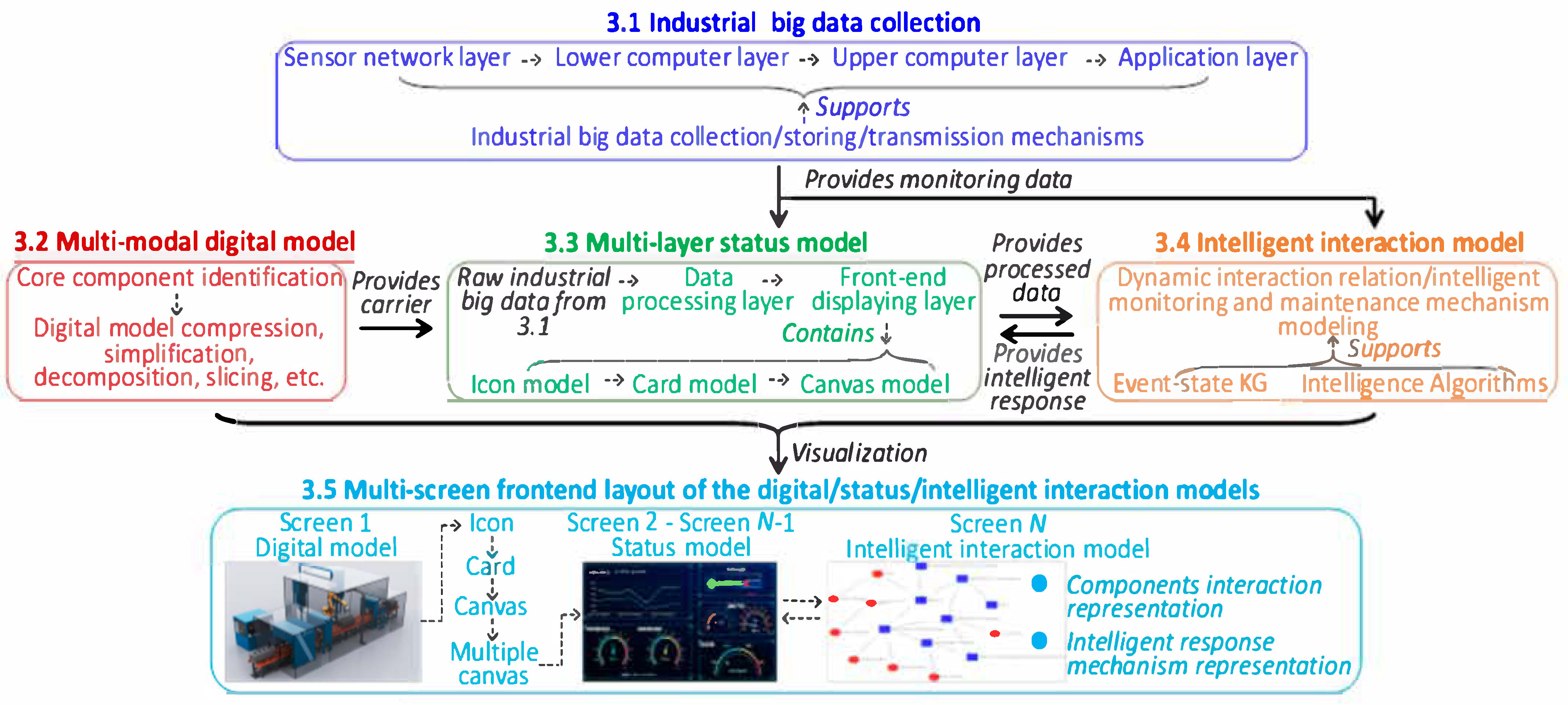
3. The Generic DT Modeling Method

The generic method for building the DT for the remote monitoring and intelligent maintenance of industrial equipment is illustrated in Figure 1, including the following:
  • Industrial big data collection, which provides a data basis for the DT
  • Digital/Status/Intelligent interaction models of the object equipment, which are the core for representing the monitoring data, and the dynamic operation/maintenance workflow and mechanisms of the DT
  • Multi-screen-based front-end layout of the DT

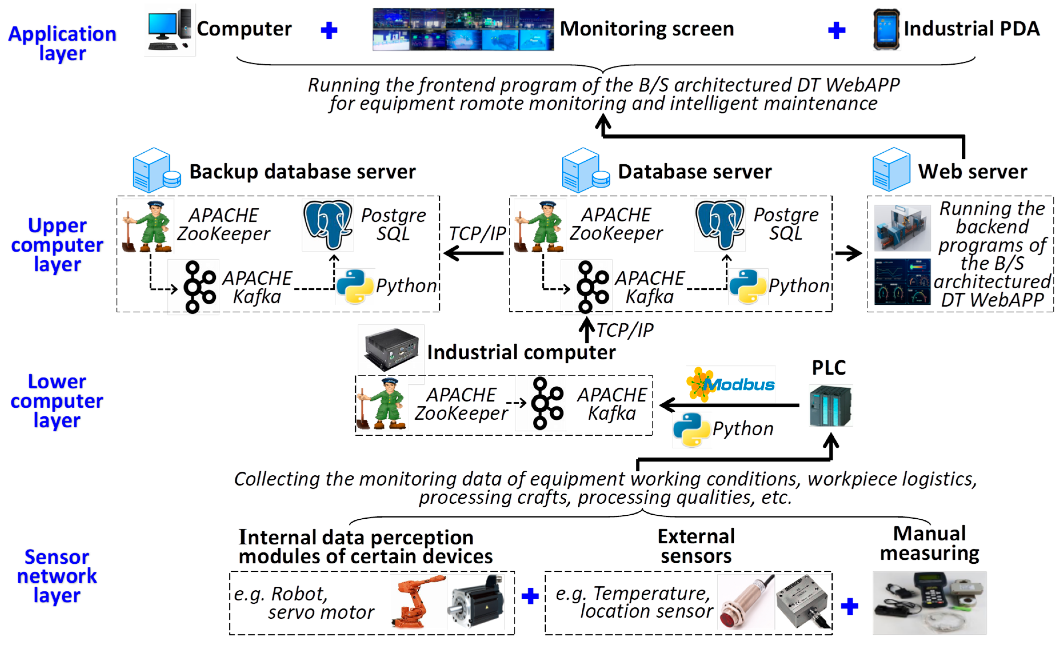
3.1. Industrial Big Data Collection for Equipment Remote Monitoring and Intelligent Maintenance

Collecting the data on equipment working conditions, workpiece logistics, processing crafts, processing quality, etc., is the basis for building the DT. In this subsection, a generic data collection framework is established for acquiring high-frequency big data for the remote monitoring and intelligent maintenance of industrial equipment. The framework contains four layers, as illustrated in Figure 2.

3.1.1. Sensor Network Layer

This layer contains three types of devices or methods for data collection, which are internal data perception modules of certain devices (e.g., electricity current data can be read from servo motors), external sensors, and manual measuring devices/methods (e.g., manually checking the quality of workpieces). It is worth mentioning that the configuration of the sensor network should be considered according to the remote monitoring and intelligent maintenance requirements of the DT and the existing data collection capability of the object equipment (i.e., the internal data perception modules of certain devices).

3.1.2. Lower Computer Layer

In this layer, firstly, PLC collects and preprocesses the data from the sensor network layer. Then, an industrial computer collects the preprocessed data from the PLC through protocols such as Modbus using a Python program. Flow data processing tools such as APACHE Kafka and ZooKeeper should be installed in the industrial computer for collecting industrial big data with the characteristics of high throughput, low latency, high concurrency, etc., and then sending the data to the database server in the upper computer layer.

3.1.3. Upper Computer Layer

In this layer, a database server is for collecting/storing/managing the data from the industrial computer through TCP/IP protocols. APACHE Kafka and ZooKeeper should be installed on the database server for industrial big data processing, and database management tools such as PostgreSQL should be installed. The data would be sent to a Web server, which runs the back-end programs of the browser/server (B/S) architecture DT WebAPPs. In addition, a backup database server should be built for collecting and storing the data from the database server for data safety.

3.1.4. Application Layer

In this layer, the front-end program of the B/S architecture DT WebAPPs, which serves as the user interface of the DT model, runs on computers, monitoring screens, industrial personal digital assistant (PDA), etc. The contents of the DT WebAPPs will be introduced in the next subsections.

3.2. Multi-Modal Digital Model

Building the corresponding digital model is an important step for building the DT of the object equipment [37]. The digital model provides not only the intuitive visualization of the equipment itself in the monitoring screens but also serves as the carrier of the status model and intelligent interaction model established in Section 3.3 and Section 3.4. For example, by adding an icon model (introduced in Section 3.3) at a certain location of a digital model, engineers would be able to intuitively read the location of the corresponding sensor of the icon mounted on the real equipment.
The digital model of an object’s equipment should be a simplified version of the original CAD model of the equipment. This is because the original CAD models are usually too large and would take too long to be loaded into the DT software program, and it is usually not required to visualize all the shape details of the equipment in a DT. In this regard, the digital model can be built in the following models according to the monitoring and maintenance requirements of the object equipment. The examples of the digital models are illustrated in Figure 3.

3.2.1. Non-Modular Configurable Digital Models

This type of digital model represents the object equipment as an integration rather than as separate parts. It can be further separated into the following two subtypes.
  • Overall model: It represents the digital model of the entire equipment, and it can be separated into (1) Simplified 3D models, which are compressed from the original 3D CAD models (such as .gltf or .draco files compressed through SolidWorks Visualize software); (2) 2D image of the Simplified 3D model; (3) 2D schematic diagram, which is further simplified from 2D image model and can be loaded even faster in the front-end DT software program;
  • Key partial model: It represents only part of the entire equipment that is important for the monitoring and maintenance tasks. It can be further separated into (1) Simplified partial 3D model, which is also the compressed and simplified version of the original 3D CAD model of the object equipment; (2) Simplified partial 2D model, which can be either the surface image or cross-section image of the object equipment.

3.2.2. Modular Configurable Digital Models

By contrast, modular configurable digital models are more suitable for the digital model of equipment with multiple configuration modules, processing lines, factories, etc. This type of digital model can also be further separated as follows.
  • Simplified 3D configuration model: This subtype is also built from compressing and simplifying the original 3D CAD model of the object equipment, but with separated and configurable modules.
  • Simplified 2D configuration model: As the name suggests, this subtype is similar to the previous one but with (1) simplified 2D images or (2) simplified 2D schematic diagrams. It is worth mentioning that the simplified 2D schematic diagram is actually the traditional configuration user interface front-end of SCADA software [38], which was established before the concept of DT.

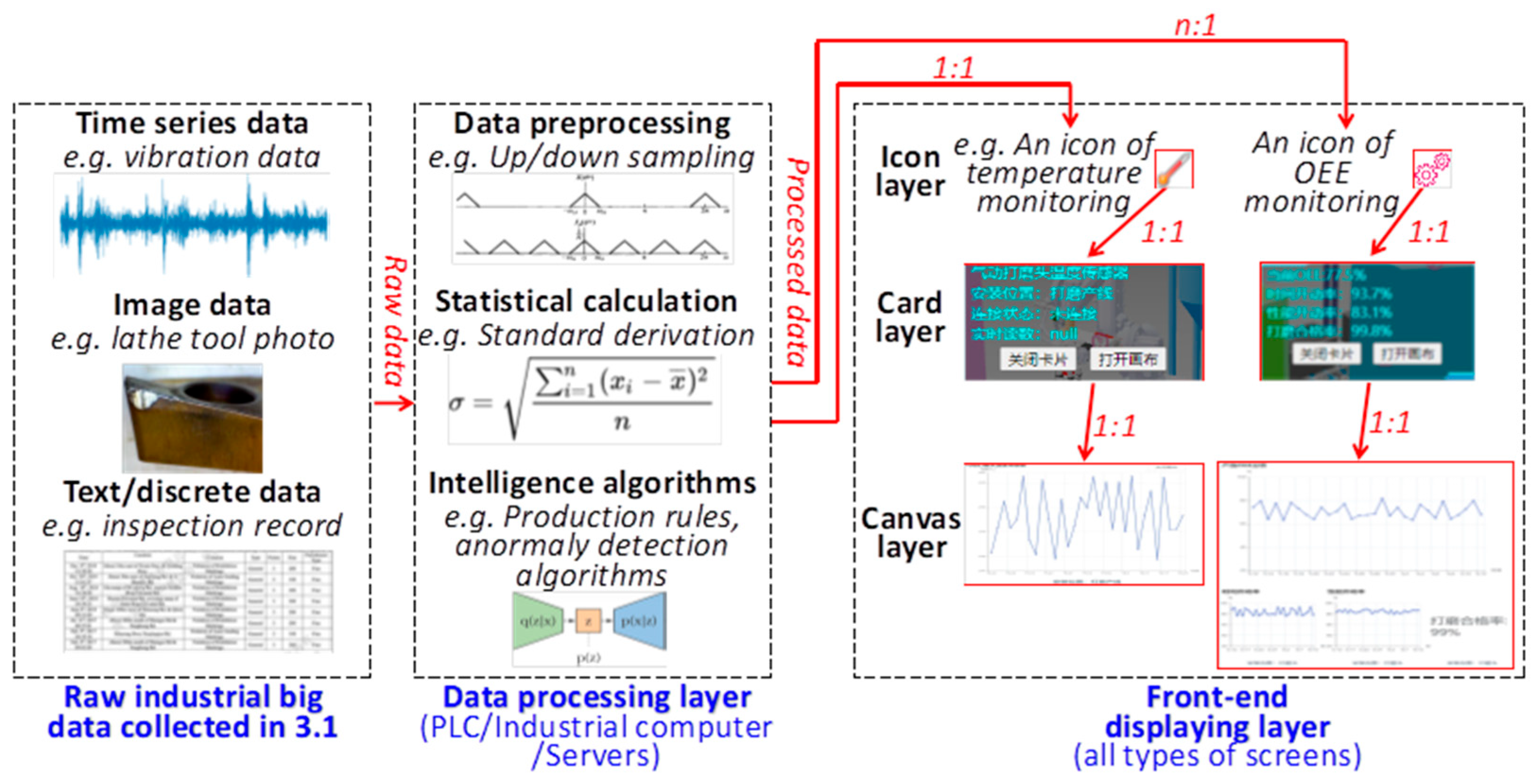
3.3. Multi-Layer Status Model

Based on the digital models in Section 3.2, a kind of multi-layer status model is established in this sub-section for processing and displaying the monitoring data collected from the sensor network layer introduced in Section 3.1. The status model can be separated into the following layers (illustrated in Figure 4).
The data processing layer is responsible for collecting raw industrial big data of equipment working conditions, workpiece logistics, processing crafts, processing qualities, etc. Here, these data would be processed with programs deployed in PLC/industrial computers/servers, etc., to extract information related to remote monitoring and intelligent maintenance. Mainly, three types of processing techniques would be conducted in this layer, as listed below.
  • Data preprocessing. It includes data cleaning, data format unifying, up/down sampling, etc., and all the functions are for providing processed data more easily for extracting valuable information from raw data.
  • Statistical calculation. It indicates using statistical calculation to extract certain features of the preprocessed data, such as standard deviations, peak values, and more complicated features, such as continuously increasing by 7 points in statistical process quality control algorithms.
  • Intelligent algorithms. It indicates applying different types of intelligent algorithms to extract monitoring and maintenance-related information from the preprocessed data. For example, production rule-based reasoning can be used for basic working condition separation, and deep learning-based anomaly detection algorithms can be used for providing early alarms of working conditions/processing crafts/processing quality anomalies.
The Front-end displaying layer emphasizes displaying the processed data from the Data processing layer, and the data would be displayed on monitoring screens in the following three sub-layers.
  • Icon layer. It is a kind of icon, each of which represents a source for data collection, and the position where the icon was placed in the digital model indicates the position of the corresponding sensor placed on the equipment.
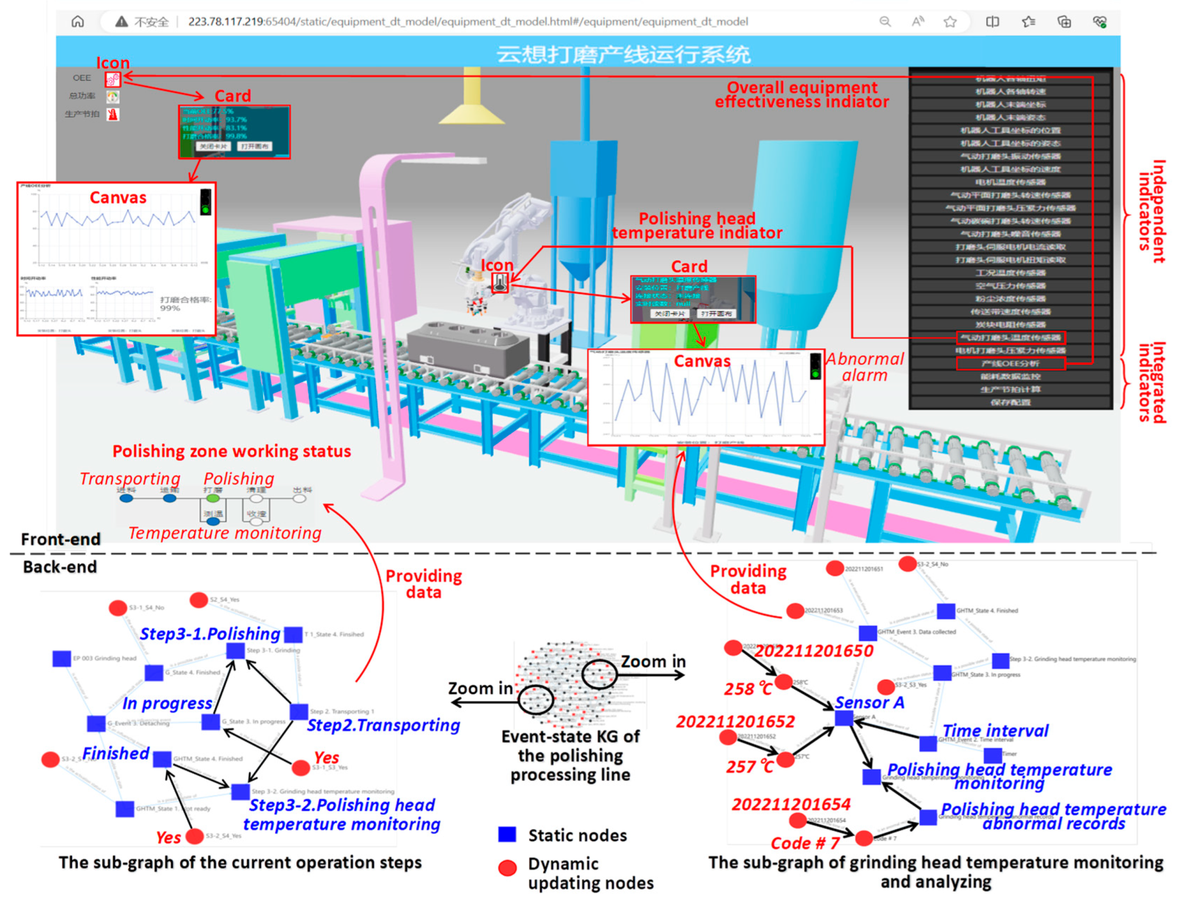
  • Card layer. By clicking an icon on the digital model, the corresponding card layer of the icon would be displayed in a pop-up window. The card would display an abstract of the corresponding data source and the sensor. For example, in Figure 4, the icon of a thermometer in the front-end interface of a DT program can be placed at the corresponding position of the thermometer on the real equipment. By clicking on the icon, the name/type/location/real-time temperature data of the thermometer would pop up in the front-end interface.
  • Canvas layer. It would pop up after clicking on the card and present more detailed descriptions of the monitoring data and the sensor. For example, the historical time series temperature data collected by the thermometer would be displayed in the canvas, and further functions such as anomaly alarm, short-term future temperature prediction, and control/optimization suggestions can also be contained in the canvas. It is worth mentioning that one icon model always corresponds to one card model, and one card model always corresponds to one canvas model. However, one icon model could correspond to one or multiple data sources. For example, a temperature icon model corresponds to a thermometer, while the overall equipment effectiveness (OEE) icon model corresponds to time activation rate data, performance rate data, and qualified product rate data.

3.4. Event-State Knowledge Graph-Based Intelligent Interaction Model

Here, a new kind of event-state KG is developed from our previous work [39,40] for providing an intelligent interaction model of the entire DT model. The event-state KG can represent the interaction relations and operation mechanisms among the components of the object equipment during its operation and maintenance. Specifically, the operation mechanisms for monitoring data collecting/storing/utilization, the monitoring data, and the time when the monitoring data were collected can be represented by the event-state KG. In addition, the event-state KG can encapsulate algorithm models (e.g., trained deep learning models, production rule models) in the KG as automatically running scripts of the event-state KG to enable automatic reacting mechanisms of the object equipment. By applying this kind of event-state KG as the back-end intelligent interaction model of the front-end digital/status models, the DT model can represent the complicated operation and maintenance mechanism of the object equipment. A kind of robot-based carbon block polishing processing line [41] is used as the modeling object of the event-state KG as an example in the rest of the paper.

3.4.1. The Nodes in the Event-State KG

Nine types of nodes are defined in the event-state KG for equipment remote monitoring and intelligent maintenance mechanism representation, as listed below.
  • A component node represents the component in the original physical system, sensor network, or status model of the equipment (e.g., in Figure 5, Visual detection module A is a component).
  • A step node represents a step during the operation process of the equipment (e.g., Step 3.1 Polishing).
  • A state node represents a possible state of a step node, which can be Not ready→ Ready→ In progress →Finished. It is worth mentioning how many states for step can be determined according to the real situation.
  • A yes/no node indicates which one of the possible states of a step node is currently activated (e.g., Yes → Not ready → Step 3.1 Polishing indicates that the state of Not ready is currently activated, which means Step 3.1 Polishing is currently Not ready).
  • An event node represents an event that can trigger the updating of the state nodes (e.g., Ready → In position → Not ready indicates that the occurrence of In position would trigger the state changing of the event node from Not ready to Ready).
  • The datum node stores one piece of monitoring data collected by a sensor component (e.g., Datum 1 → Sensor A).
  • An algorithm node represents an algorithm model (e.g., an anomaly detection (AD) algorithm model) that can process the data collected from a sensor (e.g., Sensor A → AD algorithm).
  • A calculation result node represents the calculation or analysis result of an algorithm node (e.g., Calculation result 1 → AD algorithm).
  • A time node records the time of the incident of an event or the time when a piece of monitoring data was collected (e.g., Time 1 → Datum 1).

3.4.2. The Links in the Event-State KG

The nodes defined above could be connected using thirteen types of links defined below for equipment monitoring and maintenance mechanisms representation.
  • A link that starts from step A to step B indicates that step A is the previous step of step B (e.g., Step 2. Transporting 1 → Step 3.1 Polishing).
  • A link that starts from component A to component B indicates that component A is a sub-component of component B (e.g., Polishing head → Robot).
  • A link starts from a state node to a step node indicates that the state is one of the possible states of the step (e.g., Not ready → Step 3.1 Polishing).
  • A link starts from a Yes/No node to a state node indicates that the state is currently activated/inactivated (e.g., “Yes → Not ready → Step 3.1 Polishing” indicates that Step 3.1 Polishing is currently not ready).
  • A link starts from a component node to an event node indicates that the component is the executor or the trigger of the event (e.g., “Timer → Time interval passed” indicates that the timer emits a signal at regular intervals, and it triggers the occurrence of the event of “Time interval passed”).
  • A link starts from an event node to a component node indicates that if the event occurred the component would be triggered to execute its function (e.g., “Time interval passed → Sensor A” indicates that for each time the event of “Time interval passedSensor A would collect a piece of monitoring datum).
  • A link that starts from a datum node to a component node indicates that the datum recorded in the datum node was collected by the component. In addition, a component may have collected several pieces of data and therefore be connected with several datum nodes (e.g., Datum 1 → Sensor A ← Datum2).
  • A link that starts from a time node to a datum node indicates that the datum was collected at the time (e.g., Time 1 → Datum 1)
  • A link that starts from a time node to an event node indicates that the event occurred at that time. In addition, an event may occur several times and therefore be connected with several time nodes (e.g., Time 1 → Datum collected ← Time 2).
  • A link starts from a component node to an algorithm node indicates that the data collected by the component would be sent to the algorithm model as input (e.g., Sensor A → AD algorithm).
  • A link starts from an algorithm node to an event node indicates that every time the algorithm generates a new calculation result, the event would occur (AD algorithm → New analysis result generated).
  • A link that starts from a calculation result node to an algorithm node indicates that the former records the newest calculation result of the latter (e.g., Calculation result 1 → AD algorithm).
  • A link starts from a calculation result node to an event node indicates that the updating of the calculation result would trigger the occurrence of the event (Calculation result 1→ Front-end alarm updated).

3.4.3. The Dynamic Automatic Updating Mechanisms of the Event-State KG

Based on the nodes and links in Section 3.4.2, reasoning functions can be defined to enable dynamic automatic updating of the event-state KG, thus allowing the nodes in the dashed boxes in Figure 5 to be automatically updated during the operation and maintenance of the object equipment. The basis updating mechanisms are defined below.
  • The state-changing mechanism of a step node is triggered by the state(s) changing of another (other) step node(s). It represents the working flow during the operation and maintenance of the object equipment. An example of the state-changing mechanism of Step 4 Transporting 2 triggered by the state-changing of its two previous steps (i.e., Step 3.1 Polishing and Step 3.2 Polishing head temperature monitoring) can be represented with the pseudocode below.
    Assume that currently both Step 3.1 Polishing and Step 3.2 Polishing head temperature monitoring are in the state of In progress, and Step 4 Transporting 2 is in the state of Not ready.
    If the current states of Steps 3.1 and 3.2 have been updated to Finished
      The current state of Step 4 would be automatically updated to Ready
    Else
      The current state of Step 4 remains Not ready
  • The state-changing mechanism of a step node is triggered by the occurrence of an event. For example, in Figure 5, the links of Yes → Not ready → Step 3.1 Polishing indicate that Not ready is a possible state of Step 3.1 Polishing, and currently Not ready is activated, i.e., Step 3.1 Polishing is currently not ready. The links of No → Ready → Step 3.1 Polishing indicate that Ready is another possible state of Step 3.1 Polishing, and currently Ready is not activated. The links of Ready → In position → Not ready indicate that In position is the event that could trigger the state changing from Not ready to Ready for Step 3.1 Polishing, and the trigger mechanism can be realized with the pseudocode below.
    Assume that currently Step 3.1 is not ready
    If the event of In position occurred
      The current state of Step 3.1 would be automatically updated from Not ready to Ready
    Else
      The current state of Step 3.1 remains as Not ready
  • The state-changing mechanism within a step node. It guarantees that for each step node, only one of its two states (i.e., Yes or No) can be activated at the same time. Assuming that a step node has several states, then the mechanism can be represented with the pseudocode below.
    For all the state nodes of step node n
      If state i is currently activated
        The rest state node would be inactivated
  • Monitoring data recording mechanism. It supports the automatic updating of data nodes. An example pseudocode for recording the monitoring data collected by Sensor A is listed below.
    For each time the event of the Time interval has occurred
      A new piece of monitoring data would be collected by Sensor A, and the new datum would be recorded in a newly generated datum node linked to Sensor A
      The time when the new datum was collected would be recorded in a newly generated time node linked to the newly generated datum node
  • Algorithm operation mechanism. It realizes the operation of the algorithm node for updating the monitoring/maintenance-related contents of the event-state KG. Here, a deep learning-based AD algorithm for predicting equipment anomaly according to the monitoring data from Sensor A is listed below as an example. It is worth mentioning that the mechanism here mainly defines how to integrate AI models into the event-state KG. How to build or train the AI models is not the focus of the event-state KG.
    For each time a new piece of monitoring data has been collected by the sensor connected to the AD algorithm node
      The trained AD model represented by the AD algorithm node would run with the new datum as input
      The Calculation result 1 linked to the AD algorithm would be updated according to the new output

3.5. Multi-Screen Front-End Layout of the Digital/Status/Intelligent Interaction Models

The front-end program interfaces of the digital/status/intelligent interaction models should be displayed in the monitoring screens deployed in the on-site control room, central control room, industrial PDAs, etc. It is suggested to deploy one screen for the digital model, multiple screens for the status models each of which focuses on working conditions/processing crafts/processing qualities, and another screen for the intelligent interaction model (i.e., the event-state KG) in the control room, as illustrated in the bottom of Figure 1. However, the customer company can deploy fewer screens and self-define the layouts of the contents displayed on the screens according to their specific requirements. A few examples of monitor screen layouts are introduced in Section 4.

4. Case Study

In this section, the robot-based carbon block polishing processing line [41] developed for replacing manual polishing work is used as the object equipment, as shown in Figure 6. The processing line applies a robot with a polishing head to polish the slagging and rough surfaces of carbon blocks, which are consumable materials for electrolytic aluminum production. The working environment of the processing line is harsh and not suitable for manual point/patrol inspection, thus making it a suitable object for DT application.
According to the technique in Section 3.1, more than 40 types of monitoring data were collected from the processing line, as shown in Table 1. On this basis, three real cases of different types of DT models within the range of Section 3 are presented in Section 4.1, Section 4.2 and Section 4.3. The different types of DT models were developed according to the personalized monitoring and maintenance requirements and cost demands of different customer companies. The DT models were encapsulated in a B/S architecture WebAPP developed with Python web techniques.

4.1. A DT with Configurable Module-Based Digital/Status Models but a Weak Intelligent Interaction Model

This case emphasizes establishing a configurable module-based DT model of the processing line, and the digital/status models of the DT can be configured through a drag-and-drop operation in a DT configuration APP. The case is presented with two steps, including constructing the configurable modules of the digital model of the processing line DT, and configuring the digital/status models of the DT according to specific processing line hardware.

4.1.1. Constructing the Configurable Modules of the Digital Model of the Processing Line DT

As mentioned in Section 3.2, configurable module-based DT is particularly suitable for equipment with large numbers of configurable variants. Therefore, firstly, the engineers identified the configurable modules in the equipment according to configuration design rules, e.g., high cohesion and low coupling, and also made sure that all the configurable variants of the processing line can be configured with the modules. The front-end configuration interface is shown in Figure 7.
It can be seen on the left side of the interface that the configurable modules of the processing line were separated into five categories according to their functions and assembly positions, including Polishing devices, Robot body (i.e., mechanical arm), Dust control devices, Sensors, and Auxiliary devices. The components within each category are listed below.
  • Polishing devices: Top surface polishing, Side surface polishing, Bottom surface polishing.
  • Robot body: IRB 5710, IRB 6700, IRB 7600.
  • Dust control devices: Dust cover, Vacuum cleaner, Dust collector.
  • Sensors: Thermometer, Vibrating sensor, Pressure sensor, Position sensor, etc.
  • Auxiliary devices: Centering mechanism, Clamping mechanism, Conveyor belt, Control cabinet, etc.

4.1.2. Configuring the Digital and Status Model of the DT

Based on the configurable modules in Section 4.1.1, the digital model and its corresponding status model of a processing line DT can be configured through a drag-and-drop operation according to the hardware of a specific processing line and its monitoring and maintenance requirements. A three-robot processing line was configured as an example, and the WebAPP interface of the configuration process is illustrated in Figure 7.
For the digital model of the DT, suitable components from the configurable modules (on the left side of the interface) were selected and dragged to the main window in the middle of the interface. The components dropped in the main window would be saved as components of the digital model of the processing line DT. The locations where the components were dropped were determined according to the real layout of the corresponding components of the processing line. Attribute input boxes would appear after dropping the components to define the device parameters, supplier information, price, etc., of the components.
For the status model of the DT, sensor components were selected and dragged from the left side and dropped in a suitable location on the digital model of the DT. For example, a thermometer is put on the robot. After dropping the thermometer components, the back-end addresses of the corresponding monitoring data would be defined in their input boxes, thus the monitoring data would be displayed after the digital model has been configured and deployed.
The DT in this case has a relatively weak intelligent interaction model. It mainly displays monitoring information with non-intelligent calculations. For example, on the right side of the interface, there is a status of Total power, and the total power is an approximate value calculated by adding up the power of each component without further advanced calculations.

4.2. A DT with Static 3D Digital Model, Multi-Layer Status Model, and Strong Intelligent Interaction Model

In this case, the customer company deployed a DT with a static 3D digital model, a multi-layer status model, and an event-state KG-enabled intelligent interaction model. This type of DT, compared with the one in Section 4.1, is suitable for customers with higher requirements on visualization effect, monitoring details, and intelligent reactions to monitoring data.
For the digital model, a static 3D model of the processing line was constructed, as shown in Figure 8. Compared with the digital model of the DT in Section 4.1, the digital model in this case can be rotated, flipped, and zoomed in/out to get a clear view of the processing line. However, the real-time dynamic movements of the components of the processing line cannot be indicated by this digital model. For example, it relies on the status model to indicate the current positions of the carbon blocks on the conveyor belt.
For the status model, the sensor network layer includes both external sensors (e.g., Thermometer, Vibrating sensor, Pressure sensor, Position sensor) and internal data perception modules of certain devices (e.g., the torque monitoring module in a servo motor). All the data monitored by these sensors can be displayed independently (e.g., Polishing head temperature indicator) or combined into integrated indicators with more complicated engineering meaning (e.g., OEE indicator). The Icons/Cards/Canvas of the two example indicators are illustrated in Figure 8.
For the intelligent interaction model, the event-state KG represents the dynamic interaction relations among the processing line components, together with the data collecting/storing mechanisms of the sensor network. Based on predefined query algorithms, the current/historical operation status of the processing line can be fetched and displayed in the front-end interface of the DT. For example, the sub-graph of the current operation steps in Figure 8 indicates that currently, the processing line is at the step of Polishing, and this information is shown in the bottom left of the front-end interface. The event-state KG also represents the data collecting/storing mechanisms and the data collected and stored, as shown at the bottom right of Figure 8, where the polishing head temperature data were collected by Sensor A (i.e., the 257 °C and 258 °C). In addition, an anomaly detection algorithm model was embedded in the event-state KG for intelligently predicting whether the temperature is currently normal or not according to the already collected temperature data, and the prediction result was displayed in the Canvas of the Polishing head temperature indicator in the front-end interface (i.e., the Abnormal alarm in the top right of the Canvas).

4.3. A DT with Weak Digital Model but Strong Status/Intelligent Interaction Models Represented with Split Screen

In this case, the object of the DT model was a two-robot processing line. The customer company did not require a digital model, but they required applying the canvas model for front-end visualization. They also required applying AD functions in the intelligent interaction model. In addition, the company asked for displaying certain information within one screen to provide a comprehensive and compact view of the most important indicators. In this regard, a split-screen DT was applied, and the entire screen was split into ten subareas, as illustrated in Figure 9 and introduced below.
  • Robot 1/2—Current: displaying the current data of the six axes of Robot 1/2.
  • Overall equipment effectiveness: displaying the OEE calculation result and its factors of the processing line, including Qualification rate, Time activation rate, and Performance efficiency. The monitoring object in this subarea can be constantly scrolling among integrated indicators, e.g., OEE, Overall energy consumption, and Production tact.
  • Polishing head compression force/rotation speed: including the compression force/rotation speed data of polishing heads 1 and 2.
  • Polishing head temperature: the temperature of a monitoring point on the polishing head body.
  • Dust cap temperature/pressure/dust concentration: the temperature, air pressure (should be negative pressure), and dust concentration inside the dust cap.
  • Processing line overall status: indicating whether the core functional components of the processing line are working or halting, and the position of the carbon block currently being processed. As the customer prepared only one screen for the DT, the digital model is displayed in a subarea of the screen. However, the customers can click on the digital model for an enlarged view similar to the case in Section 4.2.
  • Abnormal records: logs recording abnormal alarms.

5. Discussion and Conclusions

A generic method for building a hybrid DT model (i.e., the integration of geometric/mechanical model-driven DT and data model-driven DT) is established for supporting remote monitoring and intelligent maintenance of industrial equipment. The DT model is made up of a digital model, a status model, and an intelligent interaction model. The characteristics, contributions, and future research directions are discussed as follows.

5.1. Characteristics and Contributions

5.1.1. From a Methodology Perspective

Compared with commonly applied experience-driven monitoring and maintenance, the DT modeling method targeting a specific kind of object system, the proposed method provides a relatively more systematic and operable way to build a DT model for an object system. The proposed method can guide engineers to build their DT models step by step according to their specific equipment monitoring and maintenance requirements. It is worth mentioning that the method has been verified in building the DT models of equipment and processing lines, but we believe it also has the potential for DT modeling of larger modeling objects such as workshops and factories, as long as the modeling object has geometric models, certain types of monitoring data with certain kinds of monitoring purposes, and clear operation and interaction mechanisms among the components of the modeling objects, thus makes the method not only suitable for certain kind of equipment but also a wider range of modeling targets. It is also worth mentioning that the calculation complexity is a critical issue when the modeling objects have complicated operation workflows and interaction mechanisms.

5.1.2. From a Technique Perspective

The multi-modal digital model in Section 3.2 provides flexible options for engineers to represent the geometric structures of the DT modeling objects according to specific monitoring requirements and hardware conditions. Digital models using different modalities have different modeling costs and visualization effects; therefore, different modalities could be applied at the same time to build the digital model of an object to achieve a balance between cost and effect. For example, a 2D schematic diagram of the overall equipment can be combined with a simplified partial 3D model of certain components of the equipment when the component is important for the monitoring task. In addition, the modular configurable digital models are particularly suitable for the DT model of modularized equipment for cost reduction. It is also worth mentioning that a digital model is not essential for building a DT. In other words, a customer company may apply only status models for the monitoring task without using digital models (as shown in the case in Section 4.3).
The multi-layer status model in Section 3.3 provides a systematic method for displaying the monitoring data in the front-end interface of the DT model. It enables an intuitive display of the monitoring data as required through the icon-card-canvas rather than displaying all the data at the same time, which could cause delays between the front-end interface and the back-end database. In addition, the data processing layer of the status model can extract and merge high-value engineering information from the raw data through statistical calculation or intelligence algorithm models developed according to the monitoring and maintenance tasks. In this way, it can support the monitoring of the indicators with complicated engineering meaning based on multiple raw data sources (e.g., the OEE indicator in Figure 4).
The event-state KG-based intelligent interaction model is the key to modeling the operation/maintenance workflow and mechanisms of the object equipment. The most prominent characteristic of applying the event-state KG in the intelligent interaction model is that it can record the dynamic workflow, interaction mechanisms, and historical/current data in a computer-deployable and human-readable manner. It is worth mentioning that the event-state KG provides a way for DT models to encapsulate algorithm models, such as production rule models and trained deep learning models. By writing script programs of the event-state triggering mechanisms encapsulating the algorithm models, the event-state KG enables the DT model to automatically/intelligently react according to automatically collected monitoring data, and then the reaction information would be transformed into certain types of control instructions through the control PLC, and then the equipment would act accordingly. In this way, the overall intelligence level of the DT model can be improved.

5.2. Issue Worth Further Exploration

The digital models in Section 3.2 can also be upgraded into dynamic models. For example, in the digital model of a processing line, the workpieces being processed can be upgraded into dynamic models to indicate the real-time logistics of the workpieces. However, compared with static digital models, dynamic digital models are more complicated to build and would take more time to be loaded in the DT software program, which may result in inferior real-time performance. Therefore, dynamic digital models are only suggested for the application scenarios where the monitoring object cannot be effectively represented with static digital models. On the other hand, how to build corresponding status models and intelligent interaction models for dynamic digital models still requires further exploration.
It is also worth mentioning that the most prominent characteristic of our DT modeling method is enabled by the event-state KG-based intelligent interaction model. Compared with commonly used methods for DT modeling on the operation stage, such as unified modeling language (UML) based methods [42] and system modeling language (SysML) based methods [43], the event-state KG has the advantage of enabling human readability and computer deployability at the same time. Theoretically, the proposed method can be applied to a range of modeling objects, from equipment, processing lines, workshops, and even factories. However, the event-state KG also has its limitations, as it requires modelers to represent the operation mechanisms among the components of the modeling objects in the form of event-state triggering mechanism-based triplets. This makes the time cost and modeling difficulty of the event-state KG-based method higher than those of the UML-based and SysML-based methods. This makes the DT modeling of objects with complicated operation mechanisms not as easy as we initially expected. On the other hand, the computer deployability of the event-state KG is enabled by defining all the automatically updating mechanisms in Section 3.4.3 into program scripts, thus improving the calculation complexity of the DT model. In this regard, our future work would consider firstly developing a method that can automatically generating the event-state KG based on commonly existed industrial data of modeling objects and secondly consider simplifying the overall calculation framework of the automatically updating mechanisms, and finally we would consider building DT models of larger and more complicated objects to verify the calculation efficiency and automatic updating effects of the event-state KG.

Author Contributions

Conceptualization, P.J.; methodology, M.Y.; software, Y.C.; validation, S.S. and X.C.; writing—original draft preparation, M.Y.; writing—reviewing and editing, M.Y.; project administration, P.J.; funding acquisition, P.J. All authors have read and agreed to the published version of the manuscript.

Funding

This research was funded by the National Natural Science Foundation of China, grant number 52375512.

Data Availability Statement

The datasets presented in this article are not readily available due to confidentiality reason.

Conflicts of Interest

The authors declare no conflicts of interest.

References

  1. Toothman, M.F.; Braun, B.; Bury, S.J.; Moyne, J.; Tilbury, D.M.; Ye, Y.; Barton, K. A digital twin framework for prognostics and health management. Comput. Ind. 2023, 150, 103948. [Google Scholar] [CrossRef]
  2. Hossain, R.; Ahmed, F.; Kobayashi, K.; Koric, S.; Abueidda, D.; Alam, S.B. Virtual sensing-enabled digital twin framework for real-time monitoring of nuclear systems leveraging deep neural operators. NPJ Mater. Degrad. 2025, 9, 21. [Google Scholar] [CrossRef]
  3. Leng, J.; Zhu, X.; Huang, Z.; Xu, K.; Liu, Z.; Liu, Q.; Chen, X. ManUChain II: Blockchained smart contract system as the digital twin of decentralized autonomous manufacturing toward resilience in industry 5.0. IEEE Trans. Syst. Man Cybern. Syst. 2023, 53, 4715–4728. [Google Scholar] [CrossRef]
  4. Bai, L.; Zhang, J.; Yan, J.; López de Lacalle, L.N.; Muñoa, J. Cutting Model Integrated Digital Twin–based Process Monitoring in Small-batch Machining. Int J. Adv. Manuf. Technol. 2025, 136, 109–121. [Google Scholar] [CrossRef]
  5. Willard, J.; Jia, X.; Xu, S.; Steinbach, M.; Kumar, V. Integrating scientific knowledge with machine learning for engineering and environmental systems. ACM Comput. Surv. 2022, 55, 1–37. [Google Scholar] [CrossRef]
  6. Wang, Z.; Li, J.; Yuan, Y.; Zhang, S.; Hu, W.; Ma, J.; Tan, J. Digital-twin-enabled online wrinkling monitoring of metal tube bending manufacturing: A multi-fidelity approach using forward-convolution-GAN. Appl. Soft Comput. 2025, 171, 112684. [Google Scholar] [CrossRef]
  7. Liu, C.; Chen, Y.; Xu, X.; Che, W. Domain generalization-based damage detection of composite structures powered by structural digital twin. Compos. Sci. Technol. 2024, 258, 110908. [Google Scholar] [CrossRef]
  8. Zhou, G.; Zhang, C.; Li, Z.; Ding, K.; Wang, C. Knowledge-driven digital twin manufacturing cell towards intelligent Manufacturing. Int. J. Prod. Res. 2019, 58, 1034–1051. [Google Scholar] [CrossRef]
  9. Cao, Q.; Giustozzi, F.; Zanni-Merk, C.; Bertrand, F.; Reich, C. Smart condition monitoring for industry 4.0 manufacturing processes: An ontology-based approach. Cybern. Syst. 2019, 50, 82–96. [Google Scholar] [CrossRef]
  10. Piltan, F.; Kim, J.-M. Bearing anomaly recognition using an intelligent digital twin integrated with machine learning. Appl. Sci. 2021, 11, 4602. [Google Scholar] [CrossRef]
  11. Nguyen, T.N.; Ponciroli, R.; Bruck, P.; Esselman, T.C.; Rigatti, J.A.; Vilim, R.B. A digital twin approach to system-level fault detection and diagnosis for improved equipment health monitoring. Ann. Nucl. Energy 2022, 170, 109002. [Google Scholar] [CrossRef]
  12. VanDerHorn, E.; Wang, Z.; Mahadevan, S. Towards a digital twin approach for vessel-specific fatigue damage monitoring and prognosis. Reliab. Eng. Syst. Saf. 2021, 219, 108222. [Google Scholar] [CrossRef]
  13. Klein, C.; Wolters, F.; Reitenbach, S.; Schönweitz, D. Integration of 3D-CFD Component Simulation Into Overall Engine Performance Analysis for Engine Condition Monitoring Purposes. In Proceedings of the ASME Turbo Expo 2018: Turbomachinery Technical Conference and Exposition, Oslo, Norway, 11–15 June 2018. [Google Scholar]
  14. Li, W.; Rentemeister, M.; Badeda, J.; Jöst, D.; Schulte, D.; Sauer, D.U. Digital twin for battery systems: Cloud battery management system with online state-of-charge and state-of-health estimation. J. Energy Storage 2020, 30, 101557. [Google Scholar] [CrossRef]
  15. Li, T.; Liao, Z.; Cai, Y. Reprint of: Physical modeling for digital twin of continuous damping control damper. J. Manuf. Process. 2023, 100, 55–63. [Google Scholar] [CrossRef]
  16. Brandtstaedter, H.; Ludwig, C.; Hubner, L.; Tsouchnika, E.; Jungiewicz, A.; Wever, U. Digital Twins For Large Electric Drive Trains. In Proceedings of the 2018 Petroleum and Chemical Industry Conference Europe, Antwerp, Belgium, 5–7 June 2018. [Google Scholar]
  17. Papacharalampopoulos, A. Investigating data-driven systems as digital twins: Numerical behavior of Ho–Kalman method for order estimation. Processes 2020, 8, 431. [Google Scholar] [CrossRef]
  18. Wang, J.; Fei, Z.; Chang, Q.; Li, S. Energy saving operation of manufacturing system based on dynamic adaptive fuzzy reasoning Petri net. Energies 2019, 12, 2216. [Google Scholar] [CrossRef]
  19. He, B.; Cao, X.; Hua, Y. Data fusion-based sustainable digital twin system of intelligent detection robotics. J. Clean. Prod. 2020, 280, 124181. [Google Scholar] [CrossRef]
  20. Magargle, R.; Johnson, L.; Mandloi, P.; Davoudabadi, P.; Kesarkar, O.; Krishnaswamy, S.; Batteh, J.; Pitchaikani, A. A Simulation-Based Digital Twin for Model-Driven Health Monitoring and Predictive Maintenance of an Automotive Braking System. In Proceedings of the Linköping Electronic Conference Proceedings, Prague, Czech Republic, 15–17 May 2017. [Google Scholar]
  21. Kapteyn, M.G.; Knezevic, D.J.; Willcox, K. Toward Predictive Digital Twins via Component-Based Reduced-Order Models and Interpretable Machine Learning. In Proceedings of the AIAA SCITECH 2020 Forum, Orlando, Florida, 6–10 January 2020. [Google Scholar]
  22. Pawar, S.; Ahmed, S.E.; San, O.; Rasheed, A. Hybrid analysis and modeling for next generation of digital twins. J. Phys. Conf. Ser. 2021, 2018, 012031. [Google Scholar] [CrossRef]
  23. Kapteyn, M.G.; Willcox, K.E. Predictive Digital Twins: Where Dynamic Data-Driven Learning Meets Physics-Based Modeling. In Dynamic Data Driven Applications Systems; Darema, F., Blasch, E., Ravela, S., Aved, A., Eds.; Springer: Cham, Switzerland, 2020; Volume 12312, pp. 3–7. [Google Scholar]
  24. Liu, Z.; Meyendorf, N.; Mrad, N. The role of data fusion in predictive maintenance using digital twins. AIP Conf. Proc. 2025, 1949, 020023. [Google Scholar]
  25. Tao, F.; Qi, Q.; Wang, L.; Nee, A.Y.C. Digital twins and cyber–physical systems toward smart manufacturing and industry 4.0: Correlation and comparison. Engineering 2019, 5, 653–661. [Google Scholar] [CrossRef]
  26. Kritzler, M.; Funk, M.; Michahelles, F.; Rohde, W. The Virtual Twin: Controlling Smart Factories Using A Spatially-Correct Augmented Reality Representation. In Proceedings of the Seventh International Conference on the Internet of Things, Linz, Austria, 22–25 October 2017. [Google Scholar]
  27. Botkina, D.; Hedlind, M.; Olsson, B.; Henser, J.; Lundholm, T. Digital twin of a cutting tool. Procedia CIRP 2018, 72, 215–218. [Google Scholar] [CrossRef]
  28. Scaglioni, B.; Ferretti, G. Towards digital twins through object-oriented modelling: A machine tool case study. IFAC-PapersOnLine 2018, 51, 613–618. [Google Scholar] [CrossRef]
  29. Chhetri, S.R.; Faezi, S.; Canedo, A.; Faruque, M.A.A. QUILT: Quality Inference From Living Digital Twins In IoT-Enabled Manufacturing Systems. In Proceedings of the International Conference on Internet of Things Design and Implementation, Montreal, QC, Canada, 15–18 April 2017. [Google Scholar]
  30. Zhang, Z.; Jiang, J.; Cheng, X. Research On Digital Twin Model Of Energy Equipment. In Proceedings of the IEEE 2nd International Conference on Power, Electronics and Computer Applications, Shenyang, China, 21–23 January 2022. [Google Scholar]
  31. Ayani, M.; Ganebäck, M.; Ng, A.H.C. Digital twin: Applying emulation for machine reconditioning. Procedia CIRP 2018, 72, 243–248. [Google Scholar] [CrossRef]
  32. Luo, W.; Hu, T.; Zhang, C.; Wei, Y. Digital twin for CNC machine tool: Modeling and using strategy. J. Ambient Intell. Humaniz. Comput. 2018, 10, 1129–1140. [Google Scholar] [CrossRef]
  33. Fan, Y.; Yao, W. Research On 3D Visualization Logistics Intelligent Scheduling System Based On Digital Twin. In Proceedings of the IEEE 2nd International Conference on Electrical Engineering, Big Data and Algorithms, Changchun, China, 24–26 February 2023. [Google Scholar]
  34. Xie, N.; Kou, R.; Yao, Y. Tool condition prognostic model based on digital twin system. Procedia CIRP 2020, 93, 1502–1507. [Google Scholar] [CrossRef]
  35. Jia, W.; Wang, W.; Zhang, Z. From simple digital twin to complex digital twin part II: Multi-scenario applications of digital twin shop floor. Adv. Eng. Inform. 2023, 56, 101915. [Google Scholar] [CrossRef]
  36. Zhang, C.; Zhou, G.; He, J.; Li, Z.; Cheng, W. A data- and knowledge-driven framework for digital twin manufacturing cell. Procedia CIRP 2019, 83, 345–350. [Google Scholar] [CrossRef]
  37. Leng, J.; Lin, Z.; Huang, Z.; Ye, R.; Liu, Q.; Chen, X. Rapid simplification of 3D geometry model of mechanisms in the digital twins-driven manufacturing system design. J. Intell. Manuf. 2023, 35, 2765–2786. [Google Scholar] [CrossRef]
  38. Phuyal, S.; Bista, D.; Izykowski, J.; Bista, R. Design and implementation of cost efficient SCADA system for industrial automation. Int. J. Eng. Manuf. 2020, 10, 15–28. [Google Scholar] [CrossRef]
  39. Yang, M.; Yang, Y.; Jiang, P. A design method for edge–cloud collaborative product service system: A dynamic event-state knowledge graph-based approach with real case study. Int. J. Prod. Res. 2023, 62, 2584–2605. [Google Scholar] [CrossRef]
  40. Yang, Y.; Yang, M.; Shangguan, S.; Cao, Y.; Jiang, P. A novel method to build knowledge graph models for the configuration and operation design of smart and connected industrial products. J. Comput. Des. Eng. 2024, 11, 327–344. [Google Scholar] [CrossRef]
  41. Yang, Y.; Yang, M.; Shangguan, S.; Cao, Y.; Yue, W.; Cheng, K.; Jiang, P. An industrial case study on the monitoring and maintenance service system for a robot-driven polishing service system under industry 4.0 contexts. Systems 2023, 11, 376. [Google Scholar] [CrossRef]
  42. Luo, W.; Hu, T.; Zhu, W.; Tao, F. Digital Twin Modeling Method for CNC Machine Tool. In Proceedings of the IEEE 15th International Conference on Networking, Sensing and Control, Zhuhai, China, 27–29 March 2018. [Google Scholar]
  43. Zhang, H.; Qi, Q.; Tao, F. A multi-scale modeling method for digital twin shop-floor. J. Manuf. Syst. 2022, 62, 417–428. [Google Scholar] [CrossRef]
Figure 1. The overall architecture of the DT model.
Machines 13 00522 g001
Figure 2. A general framework of industrial big data collection for equipment remote monitoring and intelligent maintenance.
Machines 13 00522 g002
Figure 3. The classification of different models of the DT digital model.
Machines 13 00522 g003
Figure 4. The multi-layer DT status model.
Machines 13 00522 g004
Figure 5. Event-state KG-based DT intelligent interaction model (the nodes marked with dashed boxes can be automatically updated with the reasoning mechanisms in Section 3.4.3).
Machines 13 00522 g005
Figure 6. Robot-based carbon block polishing processing line, which is the case object for DT modeling.
Machines 13 00522 g006
Figure 7. A DT with configurable module-based digital/status models but a relatively weak intelligent interaction model.
Machines 13 00522 g007
Figure 8. A DT with a Static 3D digital model, multi-layer status model, and event-state KG-based intelligent interaction model.
Machines 13 00522 g008
Figure 9. A DT with a relatively weak digital model but strong status/intelligent interaction models represented with split-screen.
Machines 13 00522 g009
Table 1. Part of the monitoring data collected from a processing line.
Items Items
1Robot 1-Axis 1-Current21Robot 1-Plane polishing head-Pressure
2Robot 1-Axis 2-Current22Robot 1-Bowl polishing head-Pressure
3Robot 1-Axis 3-Current23Robot 1-Plane polishing head-Rotate speed
4Robot 1-Axis 4-Current24Robot 1-Bowl polishing head-Rotate speed
5Robot 1-Axis 5-Current25Dust cap-Temperature
6Robot 1-Axis 6-Current26Dust cap-Air pressure
7Robot 1-Axis 1-Torque27Dust cap-Dust concentration
8Robot 1-Axis 2-Torque28Conveyor belt-Position signal 1
9Robot 1-Axis 3-Torque29Conveyor belt-Position signal 2
10Robot 1-Axis 4-Torque30Conveyor belt-Position signal 3
11Robot 1-Axis 5-Torque31Conveyor belt-Position signal 4
12Robot 1-Axis 6-Torque32Conveyor belt-Position signal 5
13Robot 1-Axis 1-Rotate speed33Robot 1-on/off state
14Robot 1-Axis 2-Rotate speed34Conveyor belt-on/off state
15Robot 1-Axis 3-Rotate speed35Robot 1-Plane polishing head-on/off-state
16Robot 1-Axis 4-Rotate speed36Robot 1-Bowl polishing head-on/off-state
17Robot 1-Axis 5-Rotate speed37Robot 1-Visual module-on/off state
18Robot 1-Axis 6-Rotate speed38Vacuum cleaner-on/off state
19Robot 1-Body temperature39Counter
20Robot 1-Polishing head-Temperature40Power meter
Disclaimer/Publisher’s Note: The statements, opinions and data contained in all publications are solely those of the individual author(s) and contributor(s) and not of MDPI and/or the editor(s). MDPI and/or the editor(s) disclaim responsibility for any injury to people or property resulting from any ideas, methods, instructions or products referred to in the content.

