Article

Optimization of Hybrid Machining of Nomex Honeycomb Structures: Effect of the CZ10 Tool and Ultrasonic Vibrations on the Cutting Process

by
Oussama Beldi
1,
Tarik Zarrouk
2,3,*,
Ahmed Abbadi
1,
Mohammed Nouari
3,
Jamal-Eddine Salhi
4,5,
Mohammed Abbadi
1 and
Mohamed Barboucha
2
1
Lean Manufacturing et Modélisation Mécanique, Ecole Nationale des Sciences Appliquées, Oujda 60000, Morocco
2
Centre de Recherche (CREHEIO) de L’Ecole des Hautes Etudes d’Ingénierie, Equipe de Production Intégrée, Oujda 60000, Morocco
3
Laboratoire d’Energétique et de Mécanique Théorique et Appliquée, Ecole des Mines de Nancy, Université de Lorraine, F-88100 Saint Dié Des Vosges, France
4
Department of Pure and Applied Mathematics, Saveetha School of Engineering, SIMATS, Chennai 60210, Tamil Nadu, India
5
Laboratory of Energetics (LE), Faculty of Sciences, Abdelmalek Essaadi University, Tetouan 93000, Morocco
*
Author to whom correspondence should be addressed.
Machines 2025, 13(6), 515; https://doi.org/10.3390/machines13060515
Submission received: 20 April 2025 / Revised: 30 May 2025 / Accepted: 11 June 2025 / Published: 13 June 2025

Abstract

:
Machining Nomex honeycomb composite structures is crucial for manufacturing components that meet stringent industry requirements. However, the complex characteristics of this material require specialized machining techniques to avoid defects, ensure optimal surface quality, and preserve the integrity of the cutting tool. Thus, hybrid ultrasonic-vibration-assisted machining (HUSVAM) technology, using a CZ10 combined cutting tool, was introduced to overcome these limitations. To this end, a 3D numerical model based on the finite element method, developed using Abaqus/Explicit 2017 software, allows us to simulate the interaction between the cutting tool and the thin walls of the structure to be machined. The objective of this study was to validate a numerical model through experimental tests while quantifying the impact of critical machining parameters, including the rotation speed and tilt angle, on process performance, in terms of surface finish, tool wear, cutting force components and chip size. The numerical results demonstrated that HUSVAM technology allows for a significant reduction in the cutting force components, with a decrease of between 12% and 35%. Furthermore, this technology improves cutting quality by limiting the deformation and tearing of cell walls, while extending tool life through a significant reduction in wear. These improvements thus contribute to a substantial optimization of the overall efficiency of the machining process.

1. Introduction

Nomex honeycomb composites are lightweight materials characterized by a thin-walled hexagonal structure, consisting of aramid fiber and phenolic resin [1]. Compared to conventional metallic and non-metallic materials, these honeycomb structures have the advantage of significantly reducing mass while maintaining high levels of rigidity and mechanical strength [2,3]. Furthermore, their remarkable chemical inertness gives them high stability and optimal performance in harsh and corrosive environments [4,5,6]. In response to the growing demand for lighter and stronger solutions, the aerospace industry continues to favor the use of these structural materials [7,8]. Since their successful development, Nomex cellular composites have attracted increasing interest in various industrial sectors due to their exceptional properties, now being widely used in the design of high-performance sandwich structures and recognized as essential components of modern aerospace applications [9,10]. However, the machining of Nomex honeycomb cores poses a major challenge due to the brittleness and geometric complexity of the material, which requires specific methods to preserve its structural integrity and ensure optimal results [11,12,13]. Ultrasonic machining, a rapidly developing technology, has been adopted for cutting Nomex due to its many advantages, including reduced cutting forces, limited environmental impact, and improved accuracy. This approach encompasses innovative processes such as ultrasonic-assisted drilling, milling and turning, thus constituting a significant technological advance [14,15,16]. This technology also avoids common defects associated with conventional machining, such as wall tearing, burr formation, cellular deformations, and uncut aramid fibers [17]. In this context, Xiang et al. [18] performed ultrasonic-vibration-assisted machining on a Nomex honeycomb core using a milling cutter, in order to evaluate the influence of deflection and inclination angles, as well as the feed rate, on cutting forces and the obtained surface quality. Furthermore, Kang et al. [19] examined the impact of several parameters, including the tilt angle, feed rate, cutting depth, and ultrasonic excitation amplitude, on cutting forces. Their study found that tilt angle was the optimal machining parameter, depending on the specific operating conditions. Cui et al. [20] proposed a path planning method for machining Nomex honeycomb structures, using an ultrasonic milling cutter integrated into a robotic system. Hybrid ultrasonic machining, which combines tool rotation with axial vibrations at ultrasonic frequencies, can significantly improve the profiling quality of Nomex honeycomb structures. Several studies have demonstrated that vibration amplification, as well as increasing the spindle rotation speed, contributes to optimizing machining performance. Furthermore, it has been established that the use of longitudinal–torsional vibration modes provides a significant improvement in machining quality compared to the exclusive use of the longitudinal mode [21]. Ahmad et al. [22] conducted rotary ultrasonic machining experiments on Nomex honeycomb structures using ultrasonic circular saw blades (UCSB) and ultrasonic circular knives (UCK). Their study analyzed the impact of several parameters, including cutting width, feed rate, spindle speed, and ultrasonic tool output amplitude, on the machining quality as well as the forces generated during the process. Furthermore, a number of studies have used ultrasonic machining to improve cutting quality and reduce defects in Nomex honeycomb structures and other composite materials. For example, Yu et al. [23] proposed an optimization model for machining curved surfaces by combining different cutters. Xu et al. [24] studied the effect of rake angle parameters on the formation of machining defects, while Wang et al. [25] analyzed the influence of rake and inclination angles on surface quality. Liu et al. [26] demonstrated that the cutting width significantly affects the machining quality of honeycomb composites. Despite its potential advantages, the application of hybrid ultrasonic-vibration-assisted machining (HUSVAM) to Nomex honeycomb structures remains poorly explored and poorly understood. The industrialization of the ultrasonic-assisted hybrid machining of Nomex honeycomb structures requires a thorough understanding of the interaction mechanisms between the CZ10 tool and the honeycomb structure. However, the complexity of accessing the contact zone and the high rotation speed of the tool make it difficult to collect real-time data and limit the experimental analysis of machining phenomena. Thus, finite element modeling appears to be an essential method for studying these complex mechanisms in detail. The experimental study of Nomex honeycomb core cutting, performed via conventional and ultrasonic machining, has been the subject of numerous studies. However, investigations incorporating finite element modeling (FEM) remain limited. To date, no detailed studies on the hybrid ultrasonic machining (HUSVAM) of Nomex honeycomb structures have been identified, particularly with regard to key aspects such as cutting tool wear, chip formation and size, surface finish, and cutting force components in all directions. The development of a finite element model is essential for a thorough understanding of the mechanism of ultrasonic-assisted hybrid machining of Nomex honeycomb cores using a CZ10 tool. In this context, this article proposes a 3D model developed under Abaqus/Explicit, simulating the hybrid ultrasonic machining (HUSVAM) of Nomex honeycomb materials using a CZ10 combined cutting tool. The objective of the study is to examine in detail the machining mechanism, tool wear, and distribution of cutting forces in the three directions, as well as chip formation as a function of variations in the rotation speed and inclination angle.

2. Study Material and Cutting Tool

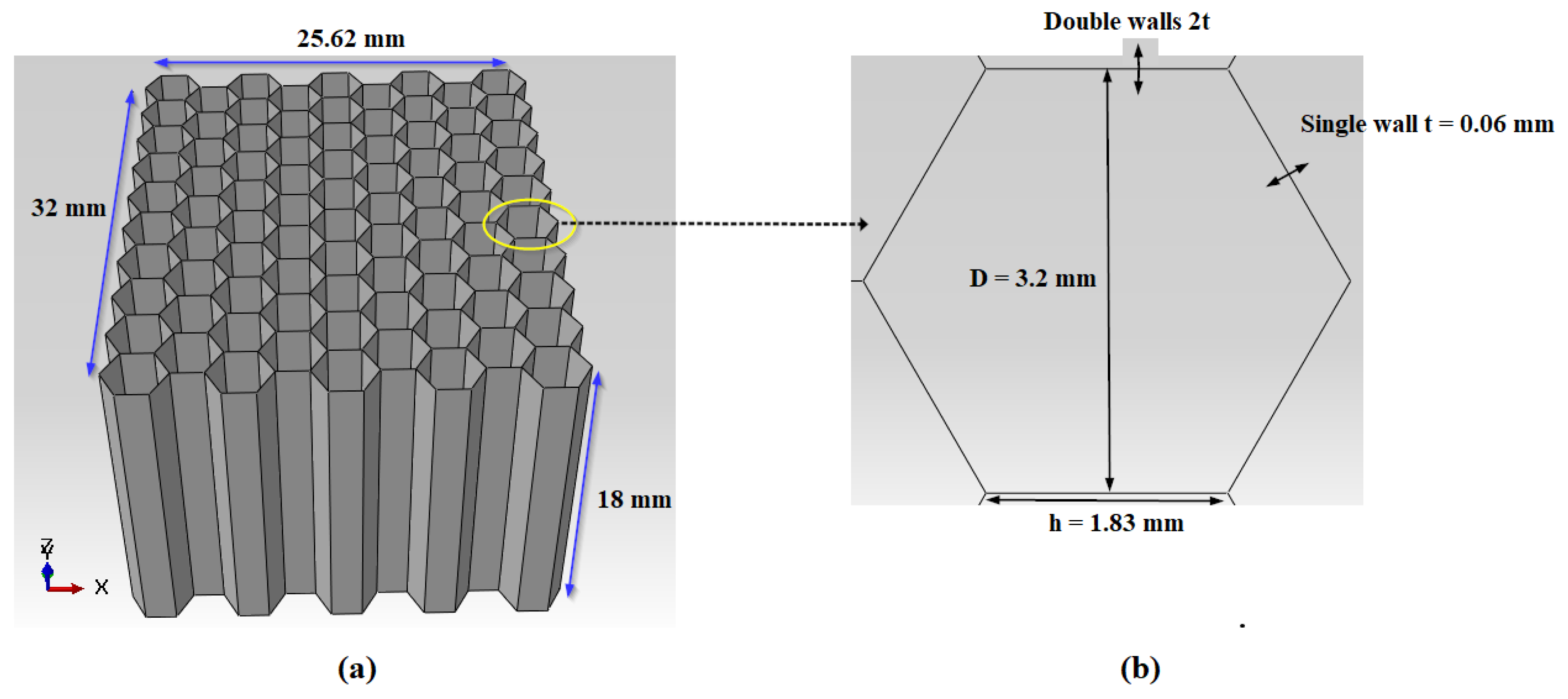
2.1. Material and Structure Studied

This study examines the cutting of Nomex honeycomb composite materials, composed of aramid fibers and phenolic resin. This type of structure is distinguished by its high mechanical strength, low density, and excellent heat resistance, making it particularly suitable for demanding industrial applications, particularly in the aeronautics and automotive sectors. In order to ensure an exact reproduction of the experimental conditions, specific and rigorously defined dimensions were chosen for the Nomex honeycomb structure, thus ensuring the reliability of the obtained results. The test sample has dimensions of 32 × 25.62 × 18 mm, corresponding to a configuration composed of 10 rows of cells in width and 19 in length. This geometric organization was chosen to provide a representative analysis of the Nomex honeycomb structure, while reproducing realistic milling conditions for the experiment (see Figure 1a). Hexagonal cells, constituting the fundamental structural element, are defined by a set of essential geometric parameters that significantly influence the mechanical properties and behavior of the structure during machining processes. The exact dimensions of these cells are detailed in Figure 1b, providing an accurate representation of their role in the overall performance of the material.

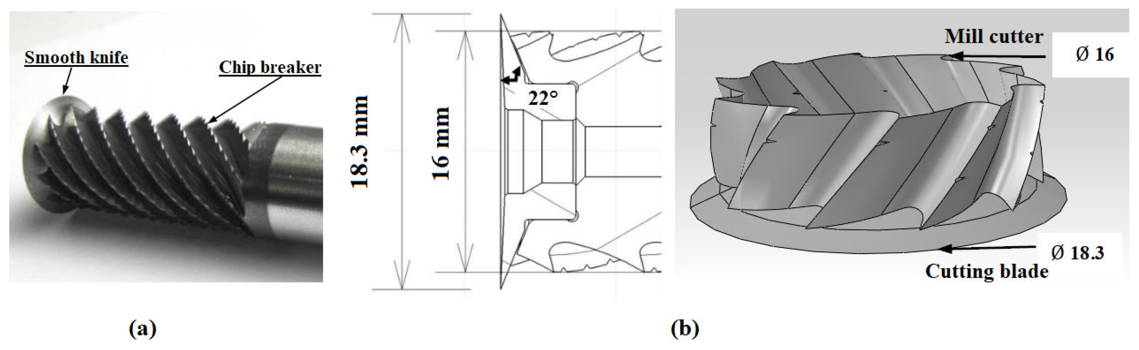
2.2. Cutting Tool Design

Due to the brittleness of Nomex paper, which is commonly used in composite structures, its machining requires the use of a range of specialized cutting tools and suitable designs to prevent damage to the material. Milling the Nomex honeycomb structure presents particular challenges due to its tendency to crack under conventional mechanical stresses. To overcome these difficulties, the selected tool is the CZ10 combined tool, a prototype developed by the company “EVATEC Tools”, which was specifically designed to meet these requirements (Figure 2a) [27]. This tool consists of two main elements: a 18.3 mm diameter conical disc, with a 22° cutting angle and a 2.5° flank angle. This ensures a precise and stable cut while reducing the friction and heat generated. The upper part of the tool is a ten-helix cutter equipped with chip breakers, facilitating the evacuation of debris and minimizing vibrations, which contributes to optimal machining (see Figure 2b).

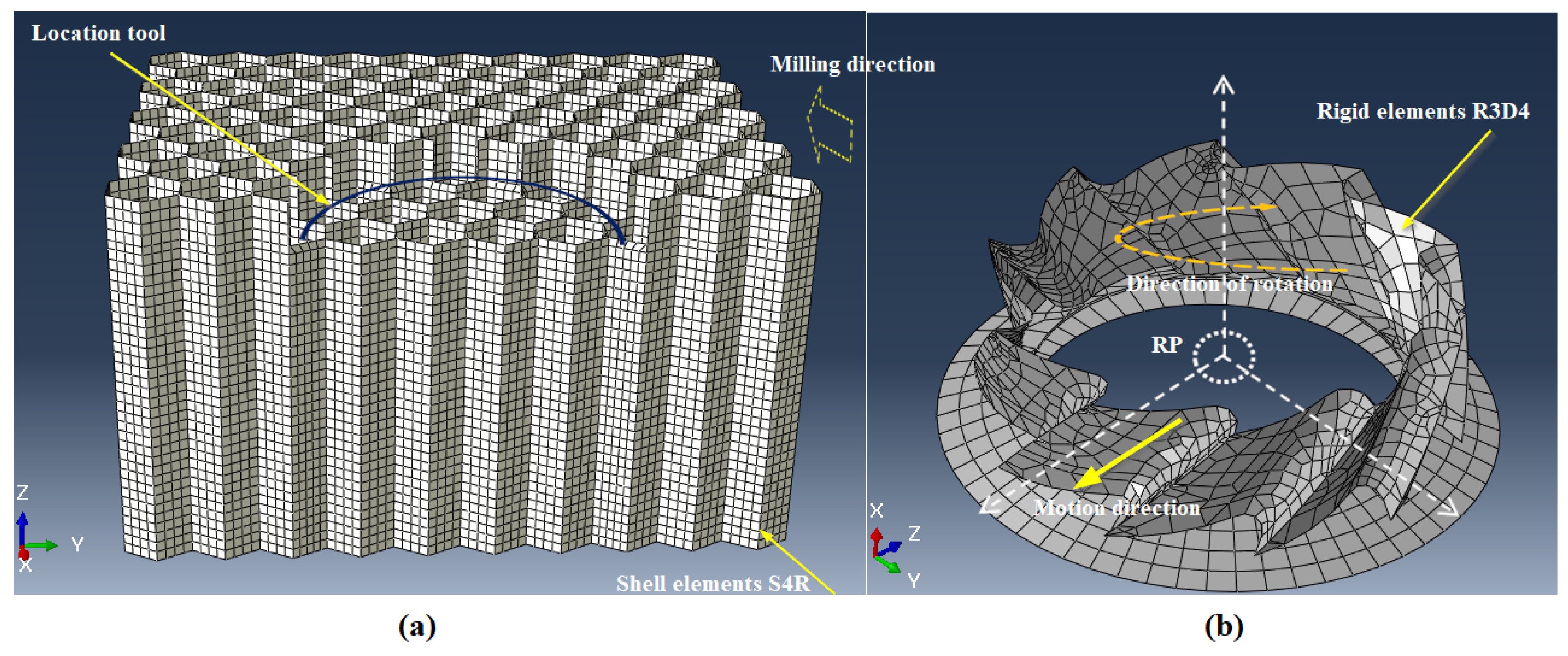
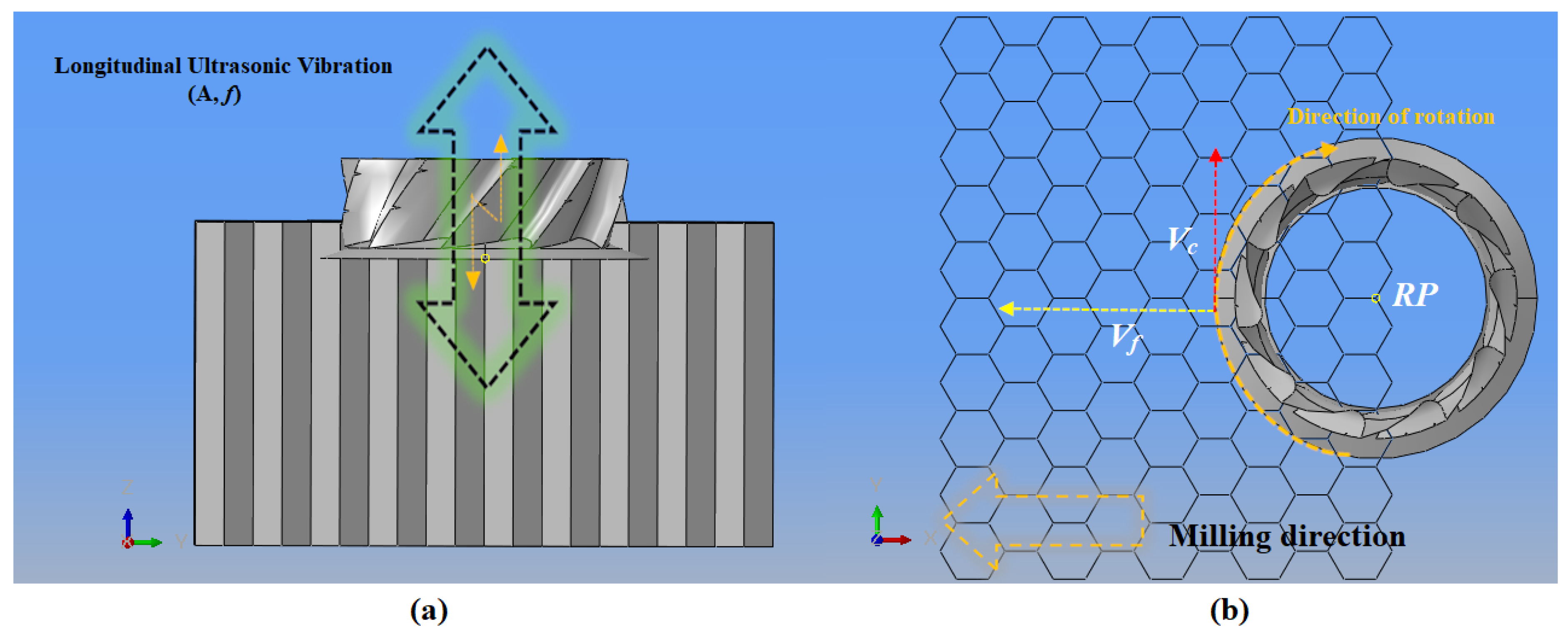
3. Description of the Numerical Model

This study presents a simulation of the process of cutting a Nomex honeycomb structure, using hybrid ultrasonic-vibration-assisted machining (HUSVAM). This approach aims to optimize the performance of the cutting process while minimizing the risks of structural degradation and preserving the integrity of the cutting tool. The simulation was carried out using a 3D numerical model, developed using Abaqus/Explicit software. This model allows for an accurate representation of the complex interactions between the cutting tool and the thin walls of the honeycomb structure, thus providing a detailed analysis of the cutting process. The Nomex honeycomb structure studied consists of single and double walls, with respective thicknesses of 0.06 mm and 0.12 mm, in accordance with the specifications of the real model. This model integrates the geometric and mechanical properties of the material described previously, thus allowing a realistic analysis of the structure’s behavior during the cutting process. To model the honeycomb structure, the thin walls were discretized using four-node S4R shell elements, providing reduced integration, as shown in Figure 3a. In this work, the cutting tool is modeled as a rigid body, which justifies the use of a surface model to geometrically represent the CZ10. This assumption simplifies the simulation while ensuring sufficient accuracy for the analysis of the interactions between the tool and the Nomex structure. Although a solid model would offer increased realism by integrating possible deformations of the tool, the assumed rigidity remains consistent with the experimental conditions and the results obtained, thus validating the relevance of the model. The modeling of the rigid tool was carried out with four-node rigid quadrangular elements (R3D4), as shown in Figure 3b. For the numerical simulations, a 0.4 mm mesh size was adopted, thus providing an optimal compromise between the accuracy of the obtained results and the efficient management of the CPU computing time. This mesh size allowed the tool and structure to be divided into fine elements, resulting in a total of 13,348 elements. This choice ensures sufficiently accurate modeling while limiting computational requirements. Regarding the contact between the tool and the part, two types of interactions are considered in the machining simulation. The first concerns the contact between the walls of the structure and the tool during its movement. The second interaction takes into account the contact between the walls themselves, following their bending after the passage of the tool, as well as between the generated chip and the unmachined walls. This approach allows for the realistic modeling of friction phenomena in the contact zone, while ensuring the numerical stability required for complex simulations. In order to account for the effects of ultrasonic vibrations applied to the cutting tool, a dynamic friction coefficient of 0.1 was adopted. This choice is based on the punctual nature of the interaction between the tool and the thin walls of the structure, which makes it possible to better represent the specific influence of ultrasonic vibrations on friction phenomena. In order to ensure continuous contact between the cutter and the structure, an initial integration was carried out, taking into account the specific geometric characteristics of the Nomex honeycomb and the CZ10 cutter (see Figure 3a). This step not only ensures optimal alignment and precise interaction between the two components but also optimizes the CPU computing time by limiting the geometric complexity of the model during simulation.
During the experimental phase, the sample is held on each side using clamps and fixing bars [27]. In our modeling, only the material located between these two bars is considered. Symmetry conditions are applied to the honeycomb walls around the Y plane (Uy = URx = URz = 0), thus simulating the maintenance of the bars and preventing any displacement in the Y direction. The workpiece is fixed to the machining table by its underside, which prevents any movement during machining. To prevent slippage, a clamping constraint is applied (Ux = Uy = Uz = URx = URy = URz = 0). Finally, additional symmetry conditions are imposed around the X-plane (Ux = URy = URz = 0) on the surface perpendicular to the x⃗ direction (Figure 4).
Hybrid ultrasonic-vibration-assisted milling (HUSVAM) combines conventional rotary milling with the application of high-frequency ultrasonic vibrations, exceeding 20 kHz, perpendicular to the cutting surface. This process integrates three motions: translation of the tool along the OX axis at a feed rate Vf, rotation of the tool around the OZ axis at a spindle speed n, and oscillation of the tool along the OZ axis, thus generating a sinusoidal ultrasonic wave (see Figure 5a. To simulate this process accurately, a reference point, denoted as RP, is placed on the axis of revolution of the cutting tool (Figure 5b). This point is essential to correctly assign the cutting parameters and evaluate the applied forces. The following equations describe the motion of the cutting tool and allow its global x, y and z coordinates to be calculated.
V x = V c cos 2 π n 60 t + V f
V y = V c sin 2 π n 60 t
V z = A cos 2 π f t
In this study, A represents the amplitude of ultrasonic vibrations, Vc denotes the cutting speed, Vf the feed rate, n the spindle speed, t the time, and f the vibration frequency. For all numerical simulations, the frequency is fixed at 21.06 kHz and the vibration amplitude at 25 µm.

4. Material Properties, Degradation and Failure Criteria

In this study, Nomex paper is represented as an isotropic elastoplastic material, the mechanical characteristics of which are specified in Table 1. During the machining process, which includes cutting the material using a cutting tool of complex design, it is essential to establish a failure criterion in order to ensure the accuracy of the simulations. The failure criteria are based on the fundamental mechanical properties of the material. In this regard, a shear-based failure criterion was chosen, and its modeling was carried out using Abaqus finite element analysis software. Chip formation occurs when the damage coefficient, d, reaches a critical threshold of 1, as defined in Equation (4), thus indicating material degradation and the start of the chip formation process.
d = ε ε f
where ∆ε represents an increment of the equivalent plastic strain and εf denotes the equivalent strain at failure.
Knowledge of cutting forces is essential for assessing machining quality and machine tool performance. These forces enable the dimensioning of machine components, the prediction of part deformations, and the analysis of chip formation, taking into account the mechanical properties of the material. Cutting forces are determined as follows [22,29]:
F x = 1 t 2 t 1 t 1 t 2 F C X d t
F y = 1 t 2 t 1 t 1 t 2 F C Y d t
F z = 1 t 2 t 1 t 1 t 2 F C Z d t
F A v g   =   F x 2 + F y 2 + F z 2
The terms FAvg, Fx, Fy, and Fz represent the cutting force and its components along the X, Y, and Z axes, expressed in newtons (N). On the other hand, FCX, FCY and FCX denote the instantaneous components of this force, also in newtons (N). The instants t1 and t2 indicate, respectively, the beginning and the end of the cutting process, measured in seconds (s).

5. Results and Discussions

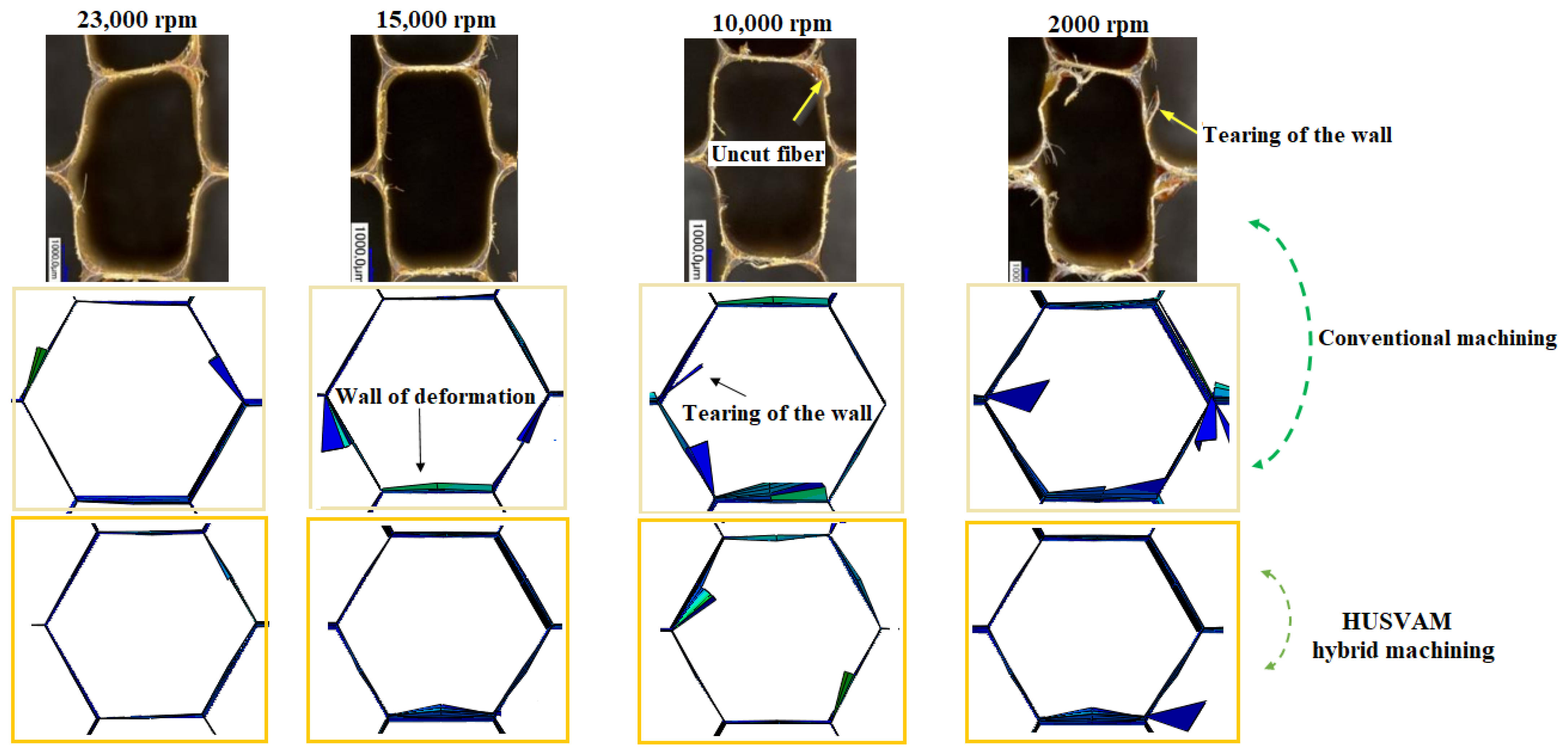
5.1. Validation of the Numerical Model for Hybrid Machining by Ultrasonic Vibrations: Study of Surface Defects as a Function of Rotation Speed

The surface quality of honeycomb structures is essential for the shaping of sandwich structures, as defects such as tears and deformations compromise the integrity of the bond to the aluminum skins. To validate the numerical model, conventional milling tests were carried out, providing a direct comparison between simulated results and experimental data. The study focused in particular on the influence of rotation speed on the surface finish, assessed using a Keyence VHX-1000 digital microscope and a three-dimensional optical profilometer. As illustrated in Figure 6, several rotation speeds, ranging from 2000 to 23,000 rpm, were studied to evaluate their impact on the surface finish in conventional milling. At the highest speed of 23,000 rpm, the walls show limited defects, although some localized tearing and deformation remain; this damage was probably caused by the significant mechanical stresses generated during the cutting process at this high speed. On the other hand, when the speed decreases to 15,000 rpm, more visible deformations appear on the walls, probably due to a loss of rigidity in the structure, linked to the heating generated during the process. At 10,000 rpm, the cutting efficiency deteriorates significantly, as evidenced by the remaining uncut fibers, a sign of poor material removal. Finally, at the lowest speed of 2000 rpm, major defects appear, including significant tearing and wall tearing, revealing an unfavorable mechanical interaction between the tool and the material, which seriously compromises the quality of the milling. The introduction of hybrid machining assisted by ultrasonic vibrations allows for a significant improvement in machining quality. Mechanically, these superimposed high-frequency vibrations reduce average cutting forces by breaking up the interaction between the tool and the material, which limits heating, reduces tear-out forces and improves cutting accuracy. This rapid cyclic action also facilitates controlled fiber breakage, reducing defects such as delamination and uncut fibers. The material is then sheared in a more clean and controlled manner, resulting in a cleaner and more uniform machined surface, even at low rotational speeds. This increased efficiency not only confirms the interest of this technology for machining thin-walled structures but also validates the ability of the numerical model to simulate advanced processes in a predictive manner. The surface quality defects analyzed in this study mainly focus on tearing and wall deformations. However, burrs were not considered, as numerical modeling does not allow for the analysis of this phenomenon. Indeed, the walls of the structure are represented by S4R shell elements, which prevents the precise evaluation of burrs. The comparison between the simulated results and the experimental tests reveals a satisfactory correspondence [27]. The main machining defects, such as uncut fibers, localized deformations and tears, are correctly predicted by the model, which validates its ability to reproduce damage mechanisms. However, slight deviations persist in certain complex areas, particularly at the junctions, where the accurate modeling of mechanical effects is more difficult. Ultimately, the visual analysis shows that hybrid machining significantly reduces machined surface defects such as tears and cell deformation, even at low speeds. This improvement is crucial to ensuring the mechanical integrity of structures, particularly in the aeronautics sector, where surface quality determines overall performance.

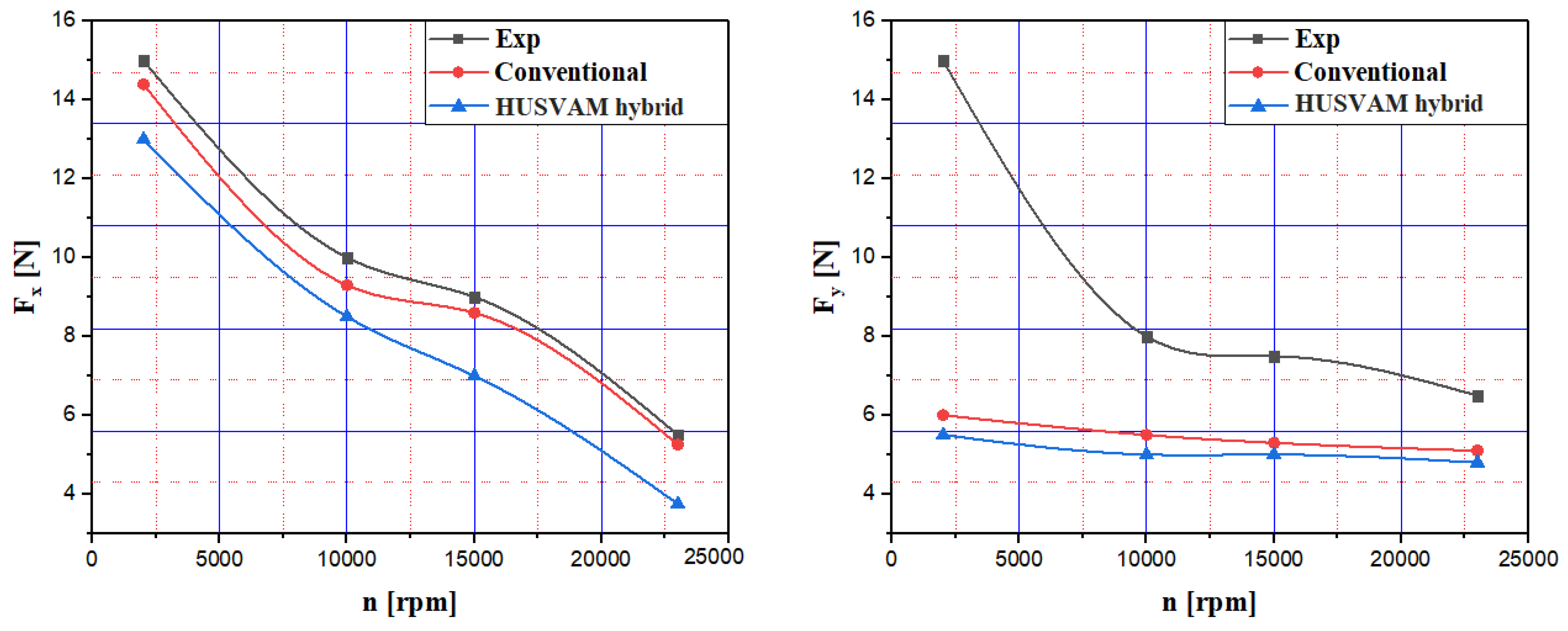
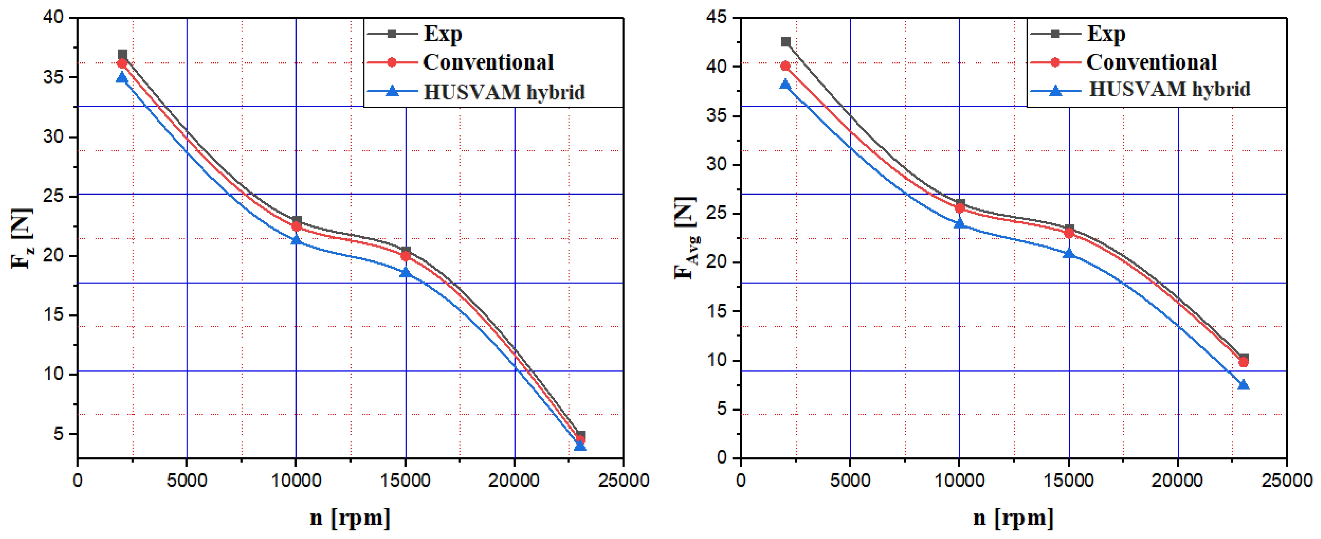
5.2. Comparison of Conventional and Hybrid HUSVAM Machining: Influence of Rotation Speed on Cutting Force and Its Components

This section uses numerical simulations to compare the performances of conventional machining and hybrid ultrasonic-vibration-assisted machining (HUSVAM) when applied to a Nomex honeycomb composite structure. The study analyzes the influence of rotation speeds, between 2000 and 23,000 rpm, on cutting forces and their three-dimensional components, keeping the cutting parameters constant: a feed rate of 3000 mm/min, an ultrasonic frequency of 21.06 kHz, and a vibration amplitude of 25 µm. The simulations were carried out on a 2 mm path with a cutting depth of 0.04 mm. The comparison highlights the effect of ultrasonic vibrations on the cutting efficiency of the Nomex structure, demonstrating a significant improvement in the process. Detailed results are illustrated in Figure 7 and Figure 8.
The analysis of the evolution of the components of the cutting force as a function of the rotation speed reveals that the conventional and hybrid processes display behavior consistent with the characteristics expected of composite materials. More precisely, the simulated results of the Fx and Fz components in conventional machining are in good agreement with the experimental data, corroborating that the increase in rotation speed induces a significant decrease in cutting forces [27]. However, a significant divergence is observed on the Fy component, with the experimental results not fully corresponding to the numerical simulations, particularly at low rotation speeds of around 2000 rpm. The disagreement observed between the numerical model and the experimental results is mainly explained by the strong influence of the force due to the elastic return of the walls at the level of the draft face. In fact, when the element reaches its breaking point, it is eliminated, which results in a loss of contact between the material and the cutting tool. This breakage causes a significant drop in cutting forces. Furthermore, the spring back of the uncut walls creates an opposing resistance to the rotation of the tool, which actually increases the cutting force. The crushing component Fz exceeds the feeding component Fx, due to the high out-of-plane geometric density of the structure, combined with the low density and intrinsic brittleness of the Nomex material. This disparity reflects the superior rigidity of the honeycomb structure compared to the limited strength of Nomex. Furthermore, hybrid ultrasonic-vibration-assisted machining (HUSVAM) results in a significant reduction in Fz, with a decrease of approximately 12% compared to conventional machining at 15,000 rpm. The physical mechanism underlying the reduction in the friction coefficient in ultrasonic-vibration-assisted machining is based on the superposition of high-frequency, low-amplitude oscillations applied to the tool. These vibrations generate intermittent and dynamic contact between the tool and the machined surface, fragmenting the continuous interaction characteristic of conventional machining. As a result, the effective contact time subjected to friction decreases, which reduces frictional forces, limits heat generation and reduces the adhesion of the aramid fibers to the tool. This phenomenon is integrated into our numerical model by a dynamic friction coefficient lowered to 0.1, reflecting the effective reduction in friction induced by vibrations. Hybrid machining assisted by ultrasonic vibrations induces a significant reduction in cutting forces, with a 35% decrease in the Fx component; this is mainly attributable to the reduction in contact between the tool and the thin walls of the structure. This phenomenon promotes smoother cutting, requiring less effort for chip formation. For the Fy component, although numerical simulations show relative stability between the conventional and hybrid processes, high-speed tests reveal a more marked reduction, amplified by the helical geometry of the CZ10 tool, which facilitates chip evacuation and reduces lateral force. Regarding the overall average force (FAvg), hybrid machining shows a progressive decrease, while it remains stable in conventional machining. Hybrid ultrasonic-vibration-assisted (HUSVAM) technology results in an average 25% reduction in cutting forces in all directions, highlighting the significant impact of ultrasonic vibrations; this is particularly beneficial for machining tough materials such as Nomex. Integrating these vibrations into the Nomex honeycomb cutting process significantly optimizes process efficiency, notably through a significant reduction in the Fx feed component, which can be as much as 35% at 23,000 rpm. This performance is also enhanced by the optimized geometry of the CZ10 tool, whose helices facilitate chip evacuation. The significant reduction in cutting forces induced by HUSVAM technology reflects better energy efficiency as well as a reduction in mechanical stresses exerted on the tool, helping to extend its service life and improve the overall reliability of the process.

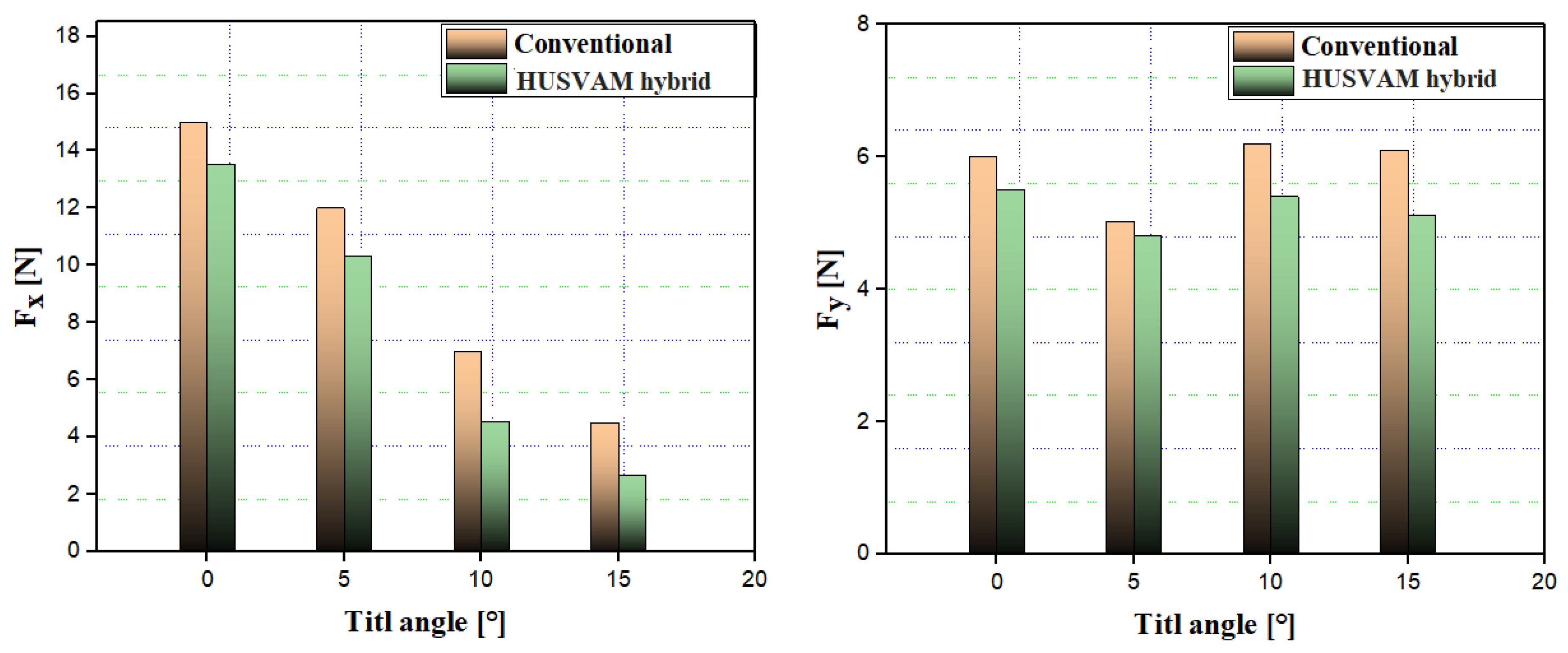
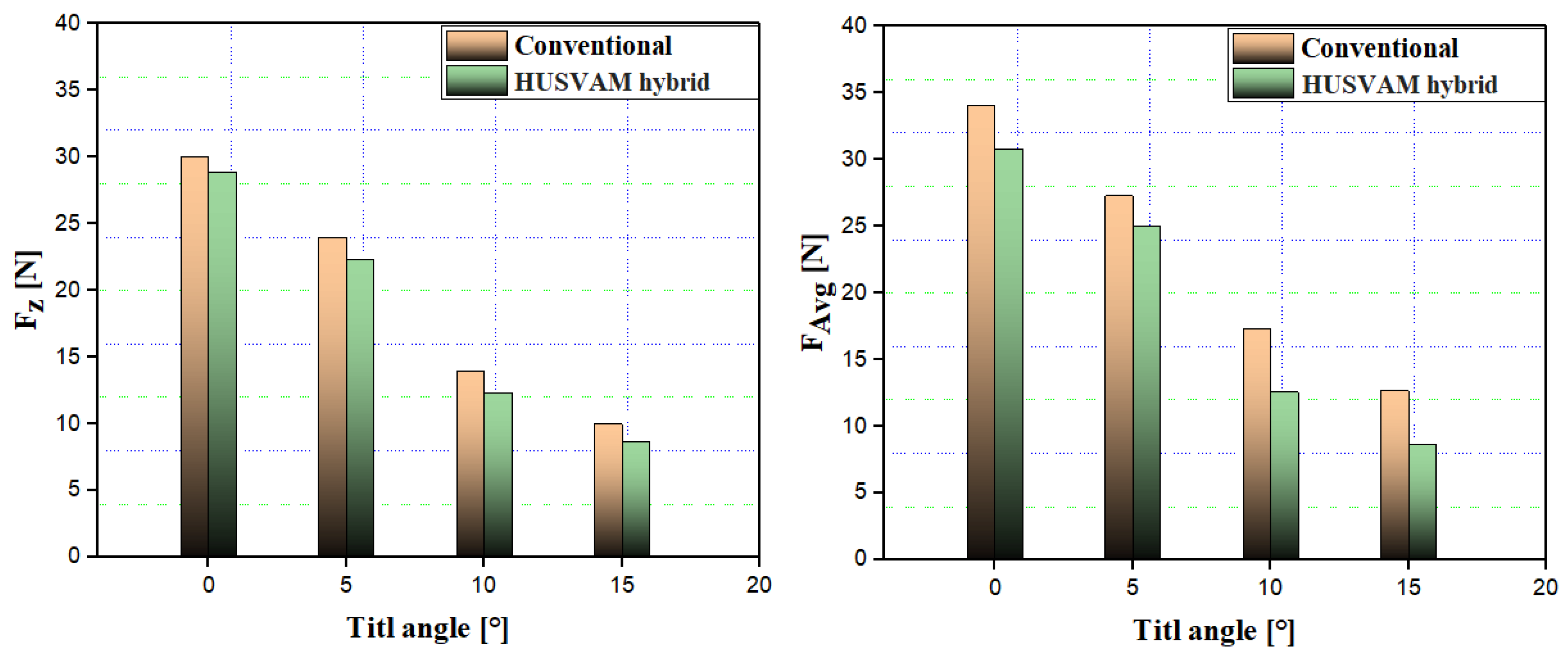
5.3. Analysis of the Impact of the Inclination Angle on the Cutting Force, Comparing Conventional and Hybrid Ultrasonic Vibration Machining

After the validation of the numerical model, we conducted a numerical analysis with the aim of studying the impact of the inclination angle on the components of the cutting force. To this end, we compared two milling techniques: conventional machining and hybrid machining assisted by ultrasonic vibrations. Simulations were carried out by varying the inclination angle according to the following values: α = 0°, α = 5°, α = 10° and α = 15°. The cutting parameters chosen for this study are as follows: a feed rate of Vf = 3000 mm/min, and a rotation speed of n = 2000 rpm. The simulations were carried out over a period of 0.04 s, corresponding to a tool displacement of approximately 2 mm. The obtained results are presented in Figure 9 and Figure 10.
The analysis of the cutting force curves allows us to evaluate the influence of the inclination angle on the force components during the milling of the Nomex honeycomb structure. This comparative evaluation focuses on two distinct processes: conventional milling and hybrid milling assisted by ultrasonic vibrations. This methodology provides a detailed understanding of the variations in cutting forces as a function of the inclination angle, while highlighting the specific effects induced by the integration of ultrasonic vibrations on the efficiency of the cutting process. The results show that the inclination angle significantly influences the cutting forces in all directions studied. In particular, the Fx component decreases progressively and regularly as the inclination angle increases. This trend is evident for both milling processes; however, ultrasonic-vibration-assisted machining induces a more pronounced reduction in feed force, which is particularly noticeable in the inclination angle range between 5° and 10°.These results suggest that a moderate inclination angle contributes to reducing the required feed force, thus optimizing the overall efficiency of the cutting process. Concerning the cutting component Fy, the variations remain moderate whatever the value of the inclination angle, both for conventional milling and for hybrid milling. Although the variations are small, ultrasonic vibrations appear to have a slight stabilizing effect, slightly reducing the lateral components and contributing to the stability of the cutting process. The Fz component, representing the crushing force, decreases significantly with as the inclination angle increases, particularly in the case of ultrasonic-vibration-assisted hybrid milling. In the inclination range between 10° and 15°, ultrasonic-vibration-assisted machining induces a significant reduction in crushing forces compared to conventional milling. This attenuation is explained by a reduction in contact between the tool surface and the material at these high angles, which facilitates the cutting process while limiting tool wear. The overall average force FAvg reveals a progressive decrease in cutting forces with an increasing inclination angle. The integration of ultrasonic vibrations contributes significantly to this reduction, optimizing process efficiency, particularly for angles between 5° and 15°, where the force reductions are most pronounced. This optimization of cutting forces generates significant benefits in terms of tool wear by reducing the abrasion and erosion of the cutting edges. In addition, the reduction in forces limits the formation of material accumulations on the edges, thus improving cutting quality and extending the tool life. The increase in the tilt angle, combined with the action of ultrasonic vibrations, promotes a significant reduction in forces, thus maximizing the efficiency of the process while minimizing the mechanical wear of the tool.

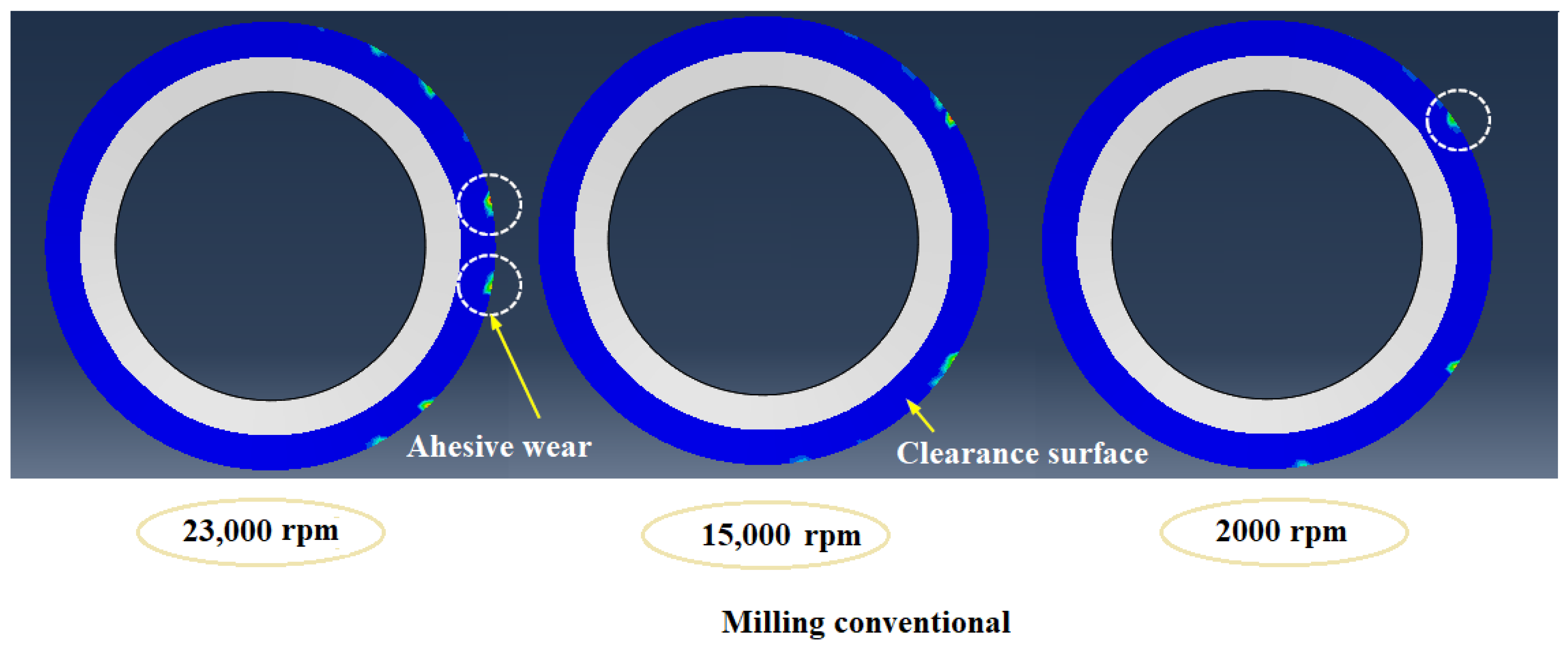
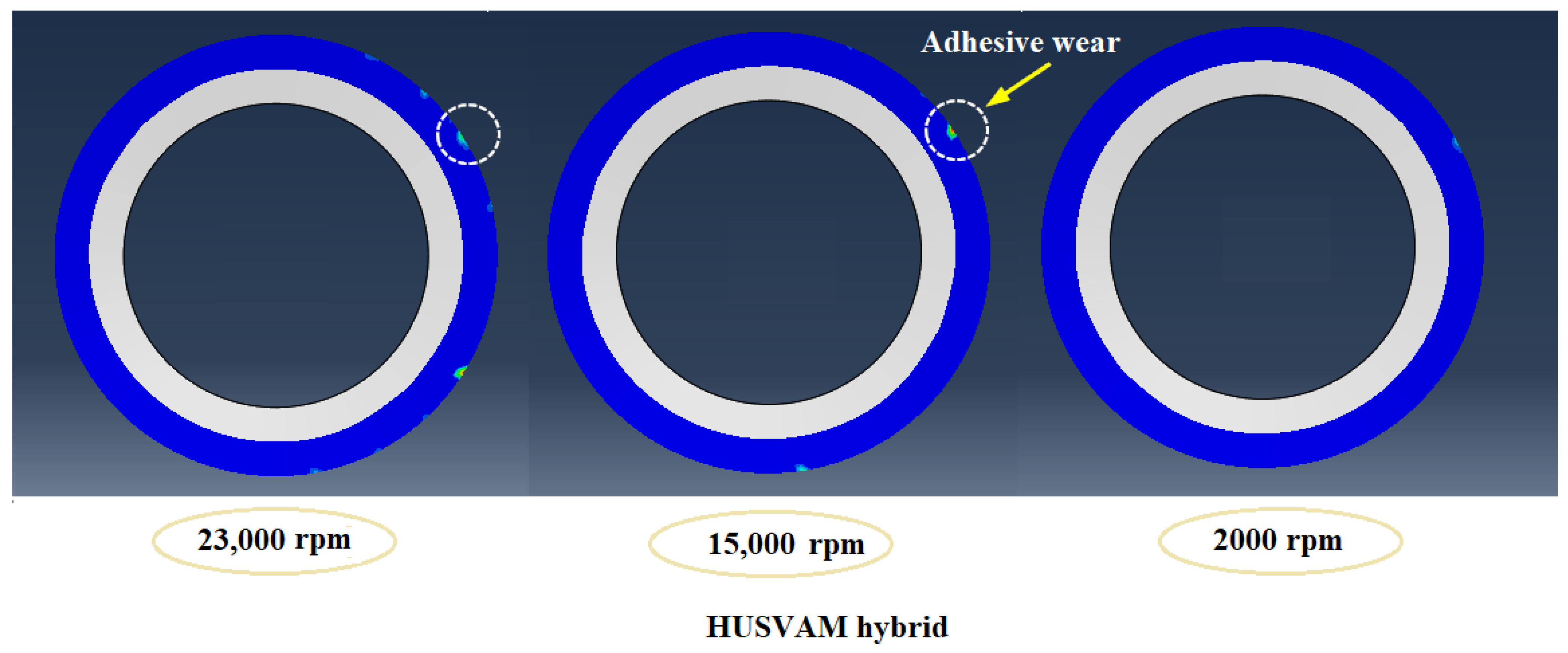
5.4. Study of Wear According to the Sticking of the Circular Knife in Conventional and Hybrid Milling Assisted by Ultrasonic Vibrations, According to the Rotation Speed

The circular knife used for milling is subject to significant mechanical constraints which accelerate its wear, making rigorous optimization of the cutting parameters imperative in order to ensure both the quality of the machining and the durability of the tools. Among the identified wear mechanisms, sticking wear stands out for its multifactorial origin, which is linked to the combination of generated heat and contact pressure exerted between the tool and the part, thus promoting the adhesion of materials on the tool clearance surface. This adhesion compromises cutting efficiency and accelerates tool degradation. Furthermore, when machining Nomex, a composite material made up of short fibers impregnated with phenolic resin, the size and morphology of the chips are highly dependent on the orientation of the fibers, as well as the cutting parameters. Two distinct morphologies were observed: at low rotation speeds associated with high feed, the chips have a large volume, while, at high speeds, they fragment into fine and dusty microchips. This differentiation highlights the crucial impact of cutting conditions on material fragmentation, directly influencing sticking wear and overall milling quality. The present study analyzes the impact of sticking wear by comparing conventional milling with ultrasonic-vibration-assisted hybrid milling, with particular emphasis on the influence of rotational speed, while keeping the feed rate constant at 3000 mm/min in all numerical simulations. Figure 11 and Figure 12 illustrate the wear results obtained for the two processes applied at different rotation speeds (2000, 10,000 and 23,000 rpm). At the maximum speed of 23,000 rpm, corresponding to a high cutting speed, conventional milling generates significant wear, characterized by the appearance of wear points due to sticking, notably materialized by traces of abrasion located in the immediate vicinity of the cutting edge. At speeds below 2000 rpm, although sticking wear is reduced, traces of abrasion persist, indicating the formation of microchips and significant pressure at the tool–material interface. The integration of ultrasonic vibrations into the milling process has a significant influence on reducing this wear. At 23,000 rpm, although some signs of sticking wear remain, their intensity is significantly reduced thanks to the high-frequency vibrations that facilitate material fragmentation. This improvement in the cutting process results in a reduction in mechanical stress and a reduction in the adhesive interaction between the tool and the machined surface, thus limiting the formation of the adhesion layer. Thus, at 23,000 rpm, hybrid milling assisted by ultrasonic vibrations significantly reduces wear due to sticking compared to conventional milling. This improvement comes mainly from the reduction in tool–workpiece contact, limiting tear-out forces and promoting the cleaner breakage of the fibers. By reducing friction and heat generation, high-frequency vibrations optimize cutting quality, improve fiber fragmentation, and preserve the machined surface. This process is particularly beneficial for machining composites, which are highly sensitive to thermal and mechanical wear, thus extending tool life and ensuring greater process stability, essential elements for ensuring reliable and efficient industrial production.

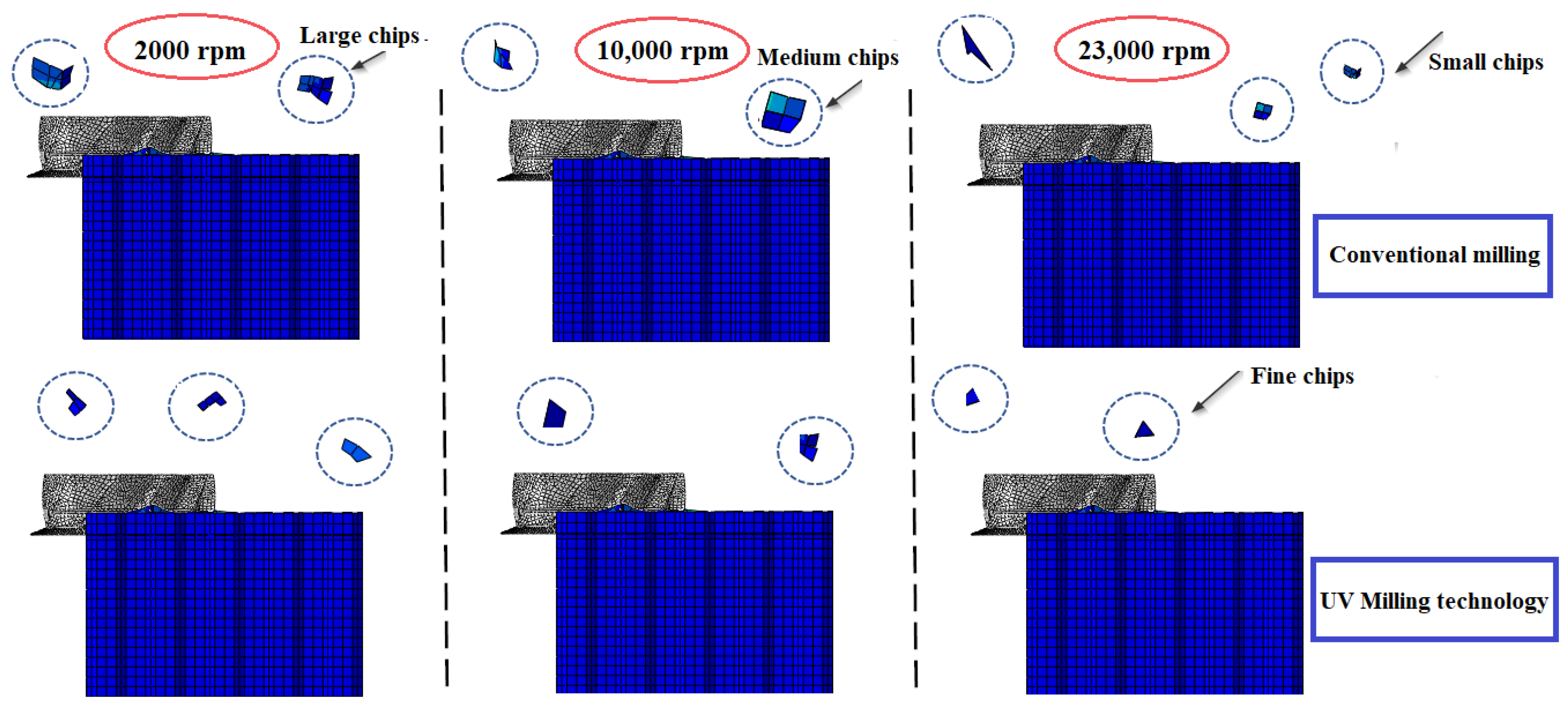
5.5. Study of Chip Formation in Conventional and Hybrid Milling Assisted by Ultrasonic Vibrations, According to Different Rotation Speeds

Mechanical machining relies on complex interactions between the cutting tool and the material to be machined. This process is difficult to observe due to the inaccessibility of interfaces during machining. Thus, 3D finite element modeling allows for a better understanding of these interactions and chip formation. In this section, the chip formation process is examined by comparing two cutting methods: namely, conventional milling and ultrasonic-vibration-assisted milling, using a combined cutting tool consisting of a milling cutter and a smooth cutter. Three rotational speeds were examined: 2000 rpm, 10,000 rpm, and 23,000 rpm, with the other conditions remaining constant for all numerical simulations, namely, a feed rate of Vf = 3000 mm/min. The obtained results are presented in Figure 13.
The CZ10 combination tool is distinguished by a difference in diameter between the circular knife and the milling cutter, which results in multi-stage chip formation. The circular knife is the first part of the tool to come into contact with the walls of the honeycomb. Chip formation begins with the initial cutting of the walls by this knife. Under the effect of rotation and feed, friction is created between the knife and the walls, causing the wall to separate into two parts. The cut portion then continues to slide on the upper surface of the knife until it reaches the body of the cutter, called the chipper, which completes the fragmentation of the chip. Figure 13 illustrates the evolution of chip size generated when milling the Nomex honeycomb at different rotational speeds. The analysis compares the obtained results in conventional and hybrid milling assisted by ultrasonic vibrations, highlighting the impact of these two factors on the size and morphology of the chips. In conventional milling, at a low rotational speed (2000 rpm), the chips generated are large and often take the form of intact walls. These chips are accompanied by tearing and chipping, reflecting a more aggressive interaction between the tool and the material. This situation occurs when the cut is less clean and cutting forces are high, resulting in increased heat generation. The optimized geometry of the CZ10 tool, with its adapted cutting sizes and specific angles, however, allows for a slight reduction in machining defects and an improvement in chip regularity, although cutting efficiency remains limited at this speed. At medium rotation speeds (10,000 rpm), the chips are medium-sized. At this speed, the interaction between the tool and the material becomes more stable, and the cut is more controlled. Thanks to its specific geometry, the CZ10 tool allows for better management of cutting forces, thus reducing wall deformation and producing more regular chips of a more moderate size. At high rotation speeds (23,000 rpm), the chips become very fine, often in the form of dust consisting mainly of aramid fibers and phenolic resin cut into smaller particles. At this speed, the cutting is very precise and the cutting forces are controlled, resulting in finely fractionated chips and improving the quality of the machined surface. The transition to hybrid milling assisted by ultrasonic vibrations allows, at low rotation speed (2000 rpm), the generation of much finer and more regular chips, quickly making the advantages compared to conventional milling visible. High-frequency vibrations reduce tear-out forces and facilitate cleaner fiber breakage, leading to a significant reduction in the formation of large chips often associated with less efficient cutting. In addition, this technology reduces friction and chip adhesion to the cutting surface, improving accuracy and resulting in a cleaner cutting surface. At medium rotation speeds (10,000 rpm), the effect of ultrasonic vibrations becomes even more pronounced. The chips generated are not only finer but also more regular compared to those produced at the same speed in conventional milling. This technology allows for the better management of cutting forces, thus facilitating cleaner chip fracturing and improving the quality of the machined surface. This process reduces the risk of premature tool wear and optimizes cutting performance. Finally, at very high rotation speeds (23,000 rpm), the addition of ultrasonic vibrations produces extremely fine chips, often in the form of dust. This reduction in chip size is particularly noticeable thanks to high-frequency vibrations, which facilitate chip fragmentation and reduce cutting forces. The analysis shows that, although increasing rotational speed in conventional milling improves chip fineness and size, integrating hybrid technology offers a significant enhancement, making the cutting process more precise and efficient even at low speeds. The CZ10 tool, thanks to its specific geometry, optimizes cutting force management and limits wall deformation, especially when combined with ultrasonic vibrations. This combination promotes the production of finer and more uniform chips, reduces tool wear, improves cutting accuracy, and prevents the formation of build-up on the cutting edge, thereby maximizing tool durability. These effects are crucial when machining composite materials such as the Nomex honeycomb structure. Hybrid machining facilitates chip evacuation, reduces clogging, and ensures better process stability, thus guaranteeing the consistent quality of the machined surfaces.

6. Conclusions

This study investigates the application of hybrid machining, combining conventional machining with ultrasonic vibration assistance, to optimize the milling of Nomex honeycomb structures. The primary objective is to reduce cutting defects while minimizing tool wear. To this end, a three-dimensional numerical model was developed using Abaqus/Explicit and validated through rigorous experimental testing. This model enables the precise simulation and analysis of the combined effects of ultrasonic vibrations and machining parameters on several key criteria, including cutting forces, surface quality, and chip management. This approach contributes to optimizing machining processes for complex composite materials by providing a better understanding of the multifactorial interactions between technical parameters. The main results highlight the following points:
  • The hybrid process assisted by HUSVAM ultrasonic vibrations of the Nomex honeycomb structure can significantly reduce the cutting force and its three components, ranging from 12% to 35%, especially for the crushing force Fx, thus improving process efficiency.
  • The hybrid process assisted by ultrasonic vibrations reduces defects typical of conventional milling, such as tearing and wall deformation, while promoting a cleaner and more consistent machined surface, even at low rotational speeds.
  • The ability of ultrasonic vibrations to reduce contact between the tool clearance surface and the material limits sticking wear, especially at lower cutting speeds. This allows for better process control and greater efficiency.
  • At low rotational speeds, ultrasonic-vibration-assisted hybrid milling minimizes sticking wear and reduces cutting forces, resulting in cleaner cutting and improved tool durability, unlike conventional milling, which generates deformations and uncut fibers.
  • By combining HUSVAM technology with the CZ10 combination cutting tool, the overall efficiency of the milling process is significantly optimized, providing a more durable, precise and high-performance solution, which is perfectly suited to the rigorous requirements of the aerospace industry.
  • This study identified the significant impact of rotational speed and tilt angle on the performance of ultrasonic vibration-assisted hybrid milling, particularly in terms of reducing cutting forces and improving surface quality. These results provide a solid basis for guiding future multi-criteria optimization to define optimal cutting parameters suited to industrial requirements.

Author Contributions

O.B.: analysis, methodology, data interpretation and results, and writing—original draft preparation. T.Z.: analysis, data interpretation and results, investigation, and writing—original draft preparation. A.A.: data interpretation and results, and writing—original draft preparation. M.N.: supervision, methodology, investigation, analysis, data interpretation and results, and writing—review and editing. J.-E.S.: data interpretation and results, and writing—original draft preparation. M.A.: data interpretation and results, and writing—original draft preparation. M.B.: data interpretation and results, and writing—original draft preparation. All authors have read and agreed to the published version of the manuscript.

Funding

This research received no external funding.

Data Availability Statement

Data are contained within the article.

Conflicts of Interest

The authors declare no conflicts of interest.

Abbreviation and Nomenclature

HUSVAMHybrid ultrasonic-vibration-assisted machining
FEMFinite element method
FAvgAverage cutting force
FxCutting force in X direction
FyCutting force in Y direction
FzCutting force in Z direction
VcCutting speed
VfFeed rate
nSpindle speed
αInclination angle
εfEquivalent strain at failure
εIncrement of equivalent plastic strain
dDamage coefficient
σStress
τShear stress
fVibration frequency
AVibration amplitude

References

  1. Li, Z.; Ma, J. Experimental Study on Mechanical Properties of the Sandwich Composite Structure Reinforced by Basalt Fiber and Nomex Honeycomb. Materials 2020, 13, 1870. [Google Scholar] [CrossRef] [PubMed]
  2. Zaharia, S.M.; Pop, M.A.; Semenescu, A.; Florea, B.; Chivu, O.R. Mechanical Properties and Fatigue Performances on Sandwich Structures with CFRP Skin and Nomex Honeycomb Core. Mater. Plast. 2017, 54, 67–72. [Google Scholar] [CrossRef]
  3. Qi, C.; Jiang, F.; Yang, S. Advanced honeycomb designs for improving mechanical properties: A review. Compos. Part B Eng. 2021, 227, 109393. [Google Scholar] [CrossRef]
  4. Li, L.; Song, J.; Lei, Z.; Kang, A.; Wang, Z.; Men, R.; Ma, Y. Effects of ambient humidity and thermal aging on properties of Nomex insulation in mining dry-type transformer. High Volt. 2020, 6, 71–81. [Google Scholar] [CrossRef]
  5. Wei, X.; Xiong, J.; Wang, J.; Xu, W. New advances in fiber-reinforced composite honeycomb materials. Sci. China Technol. Sci. 2020, 63, 1348–1370. [Google Scholar] [CrossRef]
  6. Ranga, C.; Kumar, A.; Chandel, R. Influence of electrical and thermal ageing on the mineral insulating oil performance for power transformer applications. Insight-Non-Destr. Test. Cond. Monit. 2020, 62, 222–231. [Google Scholar] [CrossRef]
  7. Klocke, F.; Soo, S.L.; Karpuschewski, B.; Webster, J.A.; Novovic, D.; Elfizy, A.; Axinte, D.A.; Tönissen, S. Abrasive machining of advanced aerospace alloys and composites. CIRP Ann. 2015, 64, 581–604. [Google Scholar] [CrossRef]
  8. Zhou, H.; Xu, P.; Xie, S.; Feng, Z.; Wang, D. Mechanical performance and energy absorption properties of structures combining two Nomex honeycombs. Compos. Struct. 2018, 185, 524–536. [Google Scholar] [CrossRef]
  9. Roy, R.; Park, S.-J.; Kweon, J.-H.; Choi, J.-H. Characterization of Nomex honeycomb core constituent material mechanical properties. Compos. Struct. 2014, 117, 255–266. [Google Scholar] [CrossRef]
  10. Liu, L.; Wang, H.; Guan, Z. Experimental and numerical study on the mechanical response of Nomex honeycomb core under transverse loading. Compos. Struct. 2015, 121, 304–314. [Google Scholar] [CrossRef]
  11. Zarrouk, T.; Salhi, J.-E.; Nouari, M.; Bouali, A. Enhancing the Machining Performance of Nomex Honeycomb Composites Using Rotary Ultrasonic Machining: A Finite Element Analysis Approach. Materials 2024, 17, 2044. [Google Scholar] [CrossRef] [PubMed]
  12. Mughal, K.H.; Qureshi, M.A.M.; Jamil, M.F.; Ahmad, S.; Khalid, F.A.; Qaiser, A.A.; Maqbool, A.; Raza, S.F.; Zhang, J. Investigation of hybrid ultrasonic machining process of Nomex honeycomb composite using a toothed disc cutter. Ultrasonics 2024, 141, 107343. [Google Scholar] [CrossRef] [PubMed]
  13. Zarrouk, T.; Nouari, M.; Salhi, J.-E.; Essaouini, H.; Abbadi, M.; Abbadi, A.; Lahlaouti, M.L. In-Depth Analysis of the Processing of Nomex Honeycomb Composites: Problems, Techniques and Perspectives. Machines 2024, 12, 561. [Google Scholar] [CrossRef]
  14. Liao, Y.; Chen, Y.; Lin, H. Feasibility study of the ultrasonic vibration assisted drilling of Inconel superalloy. Int. J. Mach. Tools Manuf. 2007, 47, 1988–1996. [Google Scholar] [CrossRef]
  15. Razfar, M.R.; Sarvi, P.; Zarchi, M.M.A. Experimental investigation of the surface roughness in ultrasonic-assisted milling. Proc. Inst. Mech. Eng. Part B J. Eng. Manuf. 2011, 225, 1615–1620. [Google Scholar] [CrossRef]
  16. Wang, Q.; Wu, Y.; Gu, J.; Lu, D.; Ji, Y.; Nomura, M. Fundamental Machining Characteristics of the In-base-plane Ultrasonic Elliptical Vibration Assisted Turning of Inconel 718. Procedia CIRP 2016, 42, 858–862. [Google Scholar] [CrossRef]
  17. Zarrouk, T.; Salhi, J.-E.; Atlati, S.; Nouari, M.; Salhi, M.; Salhi, N. Modeling and numerical simulation of the chip formation process when machining Nomex. Environ. Sci. Pollut. Res. 2021, 29, 98–105. [Google Scholar] [CrossRef]
  18. Xiang, D.; Wu, B.; Yao, Y.; Liu, Z.; Feng, H. Ultrasonic longitudinal-torsional vibration-assisted cutting of Nomex® honeycomb-core composites. Int. J. Adv. Manuf. Technol. 2018, 100, 1521–1530. [Google Scholar] [CrossRef]
  19. Kang, D.; Zou, P.; Wu, H.; Duan, J.; Wang, W. Study on ultrasonic vibration–assisted cutting of Nomex honeycomb cores. Int. J. Adv. Manuf. Technol. 2019, 104, 979–992. [Google Scholar] [CrossRef]
  20. Cui, R.; Zhang, J.; Feng, P.; Yu, D.; Wu, Z. A Path Planning Method for V-Shaped Robotic Cutting of Nomex Honeycomb by Straight Blade Tool. IEEE Access 2020, 8, 162763–162774. [Google Scholar] [CrossRef]
  21. Zarrouk, T.; Nouari, M.; Bouali, H. Numerical Modeling and Optimization of Nomex Honeycomb Core Milling: Influence of Longitudinal and Longitudinal–Torsional Ultrasonic Vibrations. Machines 2025, 13, 99. [Google Scholar] [CrossRef]
  22. Ahmad, S.; Zhang, J.; Feng, P.; Yu, D.; Wu, Z. Experimental study on rotary ultrasonic machining (RUM) characteristics of Nomex honeycomb composites (NHCs) by circular knife cutting tools. J. Manuf. Process. 2020, 58, 524–535. [Google Scholar] [CrossRef]
  23. Yu, H.; Hu, X.; Kong, L.; Yu, B. Process path planning based on efficiency model for ultrasonic cutting curved surface of honeycomb composite parts. Adv. Mech. Eng. 2019, 11, 1687814019884176. [Google Scholar] [CrossRef]
  24. Xu, Q.; Bao, Y.; Wang, Y.-Q.; Gao, H. Investigation on damage reduction method by varying cutting angles in the cutting process of rectangular Nomex honeycomb core. J. Manuf. Process. 2021, 68, 1803–1813. [Google Scholar] [CrossRef]
  25. Wang, Y.; Kang, R.; Qin, Y.; Meng, Q.; Dong, Z. Effects of inclination angles of disc cutter on machining quality of Nomex honeycomb core in ultrasonic cutting. Front. Mech. Eng. 2021, 16, 285–297. [Google Scholar] [CrossRef]
  26. Liu, G.; Yang, J.; Zhang, L.; Gao, Q.; Qian, L.; Zhang, R. Surface Quality Experimental Study on Rotary Ultrasonic Machining of Honeycomb Composites with a Circular Knife Cutting Tool. Crystals 2022, 12, 725. [Google Scholar] [CrossRef]
  27. Jaafar, M. Étude Expérimentale et Simulation Numérique de L’usinage des Matériaux en nids D’abeilles: Application au Fraisage des Structures Nomex® et Aluminium. Ph.D. Thesis, Université de Lorraine, Metz, France, 2018. [Google Scholar]
  28. Foo, C.C.; Chai, G.B.; Seah, L.K. Mechanical properties of Nomex material and Nomex honeycomb structure. Compos. Struct. 2007, 80, 588–594. [Google Scholar] [CrossRef]
  29. Jenarthanan, M.; Jeyapaul, R. Optimisation of machining parameters on milling of GFRP composites by desirability function analysis using Taguchi method. Int. J. Eng. Sci. Technol. 2018, 5, 22–36. [Google Scholar] [CrossRef]
Figure 1. Geometry and dimensions of the honeycomb structure: (a) overall view of the structure with its total dimensions; (b) geometrical details and dimensions of an individual hexagonal cell.
Machines 13 00515 g001
Figure 2. (a) Actual CZ10 cutting tool used in the experiment, highlighting its main features. (b) 3D model of the CZ10 tool showing its geometric dimensions.
Machines 13 00515 g002
Figure 3. Mesh representation of the numerical model: (a) Nomex honeycomb structure with thin-wall discretization; (b) mesh of the CZ10 cutting tool highlighting the reference point (RP) used for the cutting process simulation.
Machines 13 00515 g003
Figure 4. Boundary conditions applied to the Nomex honeycomb structure in the numerical model.
Machines 13 00515 g004
Figure 5. (a) Illustration of the hybrid ultrasonic-vibration-assisted milling (HUSVAM) process showing tool movements and longitudinal ultrasonic vibrations; (b) schematic of conventional milling conditions without ultrasonic assistance.
Machines 13 00515 g005
Figure 6. Evolution of machined surface quality obtained by simulations and experiments [27].
Machines 13 00515 g006
Figure 7. Variation in the cutting force components Fx and Fy as a function of rotational speed during conventional and HUSVAM [27].
Machines 13 00515 g007
Figure 8. Variation in the cutting force components Fz and FAvg as a function of rotational speed during conventional and HUSVAM [27].
Machines 13 00515 g008
Figure 9. Effect of tilt angle on forces Fx and Fy, with a comparison between conventional and HUSVAM milling.
Machines 13 00515 g009
Figure 10. Effect of tilt angle on forces Fz and FAvg, with a comparison between conventional and HUSVAM milling.
Machines 13 00515 g010
Figure 11. Wear propagation analysis due to sticking at different rotational speeds in conventional milling.
Machines 13 00515 g011
Figure 12. Wear propagation analysis due to sticking at different rotational speeds in hybrid milling.
Machines 13 00515 g012
Figure 13. Comparison of chip size in conventional milling and hybrid milling with regard to the rotational speed.
Machines 13 00515 g013
Table 1. Mechanical properties of Nomex paper [9,28].
Density [g/cm3]Young’s Modulus [MPa]Poisson’s Ratio
1.434000.3
Disclaimer/Publisher’s Note: The statements, opinions and data contained in all publications are solely those of the individual author(s) and contributor(s) and not of MDPI and/or the editor(s). MDPI and/or the editor(s) disclaim responsibility for any injury to people or property resulting from any ideas, methods, instructions or products referred to in the content.

