Article

Design and Implementation of a Bionic Marine Iguana Robot for Military Micro-Sensor Deployment

1
School of Mechanical Engineering, Zhejiang Sci-Tech University, Hangzhou 310018, China
2
Xiangshan Knitting Research Institute Co., Ltd., Zhejiang Sci-Tech University, Ningbo 315700, China
3
School of Information Science and Engineering, Zhejiang Sci-Tech University, Hangzhou 310018, China
4
School of Mechanical and Automotive Engineering, South China University of Technology, Guangzhou 510640, China
*
Author to whom correspondence should be addressed.
Machines 2025, 13(6), 505; https://doi.org/10.3390/machines13060505
Submission received: 3 May 2025 / Revised: 30 May 2025 / Accepted: 6 June 2025 / Published: 9 June 2025
(This article belongs to the Special Issue Design and Application of Bionic Robots)

Abstract

Underwater sensor deployment in military applications requires high precision, yet existing robotic solutions often lack the maneuverability and adaptability required for complex aquatic environments. To address this gap, this study proposes a bio-inspired underwater robot modeled after the marine iguana, which exhibits effective crawling and swimming capabilities. The research aims to develop a compact, multi-functional robot capable of precise sensor deployment and environmental detection. The methodology integrates a biomimetic mechanical design—featuring leg-based crawling, tail-driven swimming, a deployable head mechanism, and buoyancy control—with a multi-sensor control system for navigation and data acquisition. Gait and trajectory planning are optimized using kinematic modeling for both terrestrial and aquatic locomotion. Experimental results demonstrate the robot’s ability to perform accurate underwater sensor deployment, validating its potential for military applications. This work provides a novel approach to underwater deployment robotics, bridging the gap between biological inspiration and functional engineering.

1. Introduction

In modern military strategy, the ability to control and monitor maritime domains is directly related to national security and interests. With the increasing development of marine resources and maritime military activities, the construction of underwater sensor networks [1,2,3,4] has become a crucial component of military technological advancement. Military underwater sensor networks can monitor the marine environment in real-time [1], track underwater targets [2], perform reconnaissance missions [4], and provide critical intelligence support for underwater operations. Therefore, the deployment of military micro-sensors is essential for building a comprehensive underwater sensor network.
Traditional sensor deployment methods typically rely on large equipment or manual operations, which are often costly, labor-intensive, and prone to exposing targets, significantly increasing the risks of military operations. Therefore, it is necessary to introduce underwater sensor deployment robots to reduce manual labor and the risks associated with such operations.
Among these, bionic robots applied in marine environments have gained widespread use due to their strong mobility and adaptability [5]. For example, Prahacs et al. designed a bio-inspired hexapod robot with excellent adaptability for monitoring in complex aquatic environments with multiple obstacles [6]. However, its inability to precisely place sensors limits its utility in constructing reliable underwater sensor networks—a critical requirement for military surveillance, where misaligned nodes can create blind spots in detection coverage. Chen et al. designed a beaver-like robot with an RL-based control algorithm for offline training, stabilizing pitch within ±0.305 rad and reaching 0.38 m/s in underwater simulations [7]. Similarly, Cao et al. developed an efficient underwater flapping robot with high load capacity [8], but its structural complexity and cost hinder scalable deployment for large-area sensor networks. Gao et al. designed a dual-drive bionic jellyfish robot based on compliant mechanisms [9]. It achieves water-pumping propulsion through bionic finlets based on flexible mechanisms and underwater jet propulsion through tubular origami mechanisms. This effectively improves the motion efficiency, but it has limited load capacity and is sensitive to the water flow environment. Additionally, Fabeem A et al. designed a bionic soft octopus robot with highly responsive and capable tentacles [10]. Chen G et al. developed an underwater robot inspired by the mantis shrimp, driven by ten rigid swimming legs [11], capable of achieving high underwater speeds, making it suitable for underwater exploration tasks. Guo et al. designed a flapping myliobatid-inspired underwater robot [12], capable of performing various maneuvers in water, including rolling, small-radius turns, and barrel rolls, with high flexibility. Overall, bio-inspired robots in marine applications are trending towards diverse designs, high performance, intelligent functionality, and broad applications. However, most of the current sensor networks focus on environmental monitoring and data collection, some focus on flexible mobility, and some lack specialized sensor deployment design. This oversight is consequential: ad hoc sensor placement reduces data fidelity, increases network maintenance costs, and compromises mission-critical operations like mine detection or submarine tracking.
To address these issues, this paper designs a bionic marine iguana robot capable of amphibious operation, visual detection, and remote control. The robot can move flexibly in complex underwater environments and achieve precise micro-sensor deployment through its head structure. This paper focuses on the design and motion control of the bionic marine iguana robot. The main contributions are as follows:
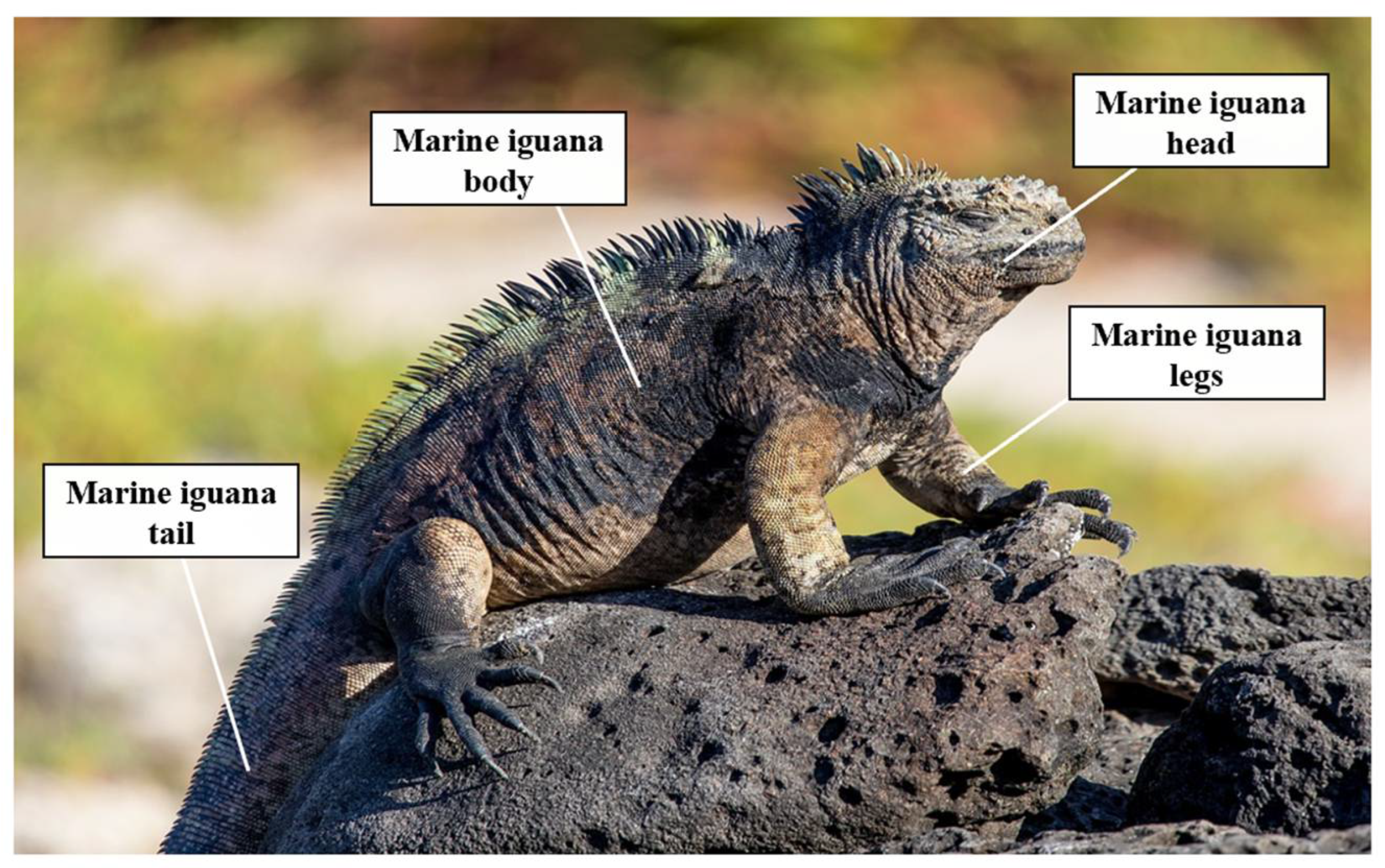
  • Based on the marine iguana’s motion characteristics, a dual-mode underwater sensor deployment robot is designed. The robot is driven by powerful limbs in crawling mode and by a tail swimming structure in swimming mode. It can ascend and descend through a flexible buoyancy adjustment mechanism and deploy underwater sensors using its head deployment structure, enabling flexible movement in complex terrains and overcoming the limitations of traditional equipment in complex waters.
  • The robot’s crawling gait planning, trajectory planning, swimming posture planning, and dynamic analysis are conducted. The Trot gait and segmented composite foot trajectory are selected to enhance the robot’s environmental adaptability and task execution. Experimental results validate the effectiveness and rationality of the trajectory planning, showing that the robot can adapt well to complex terrains such as gravel and mud.
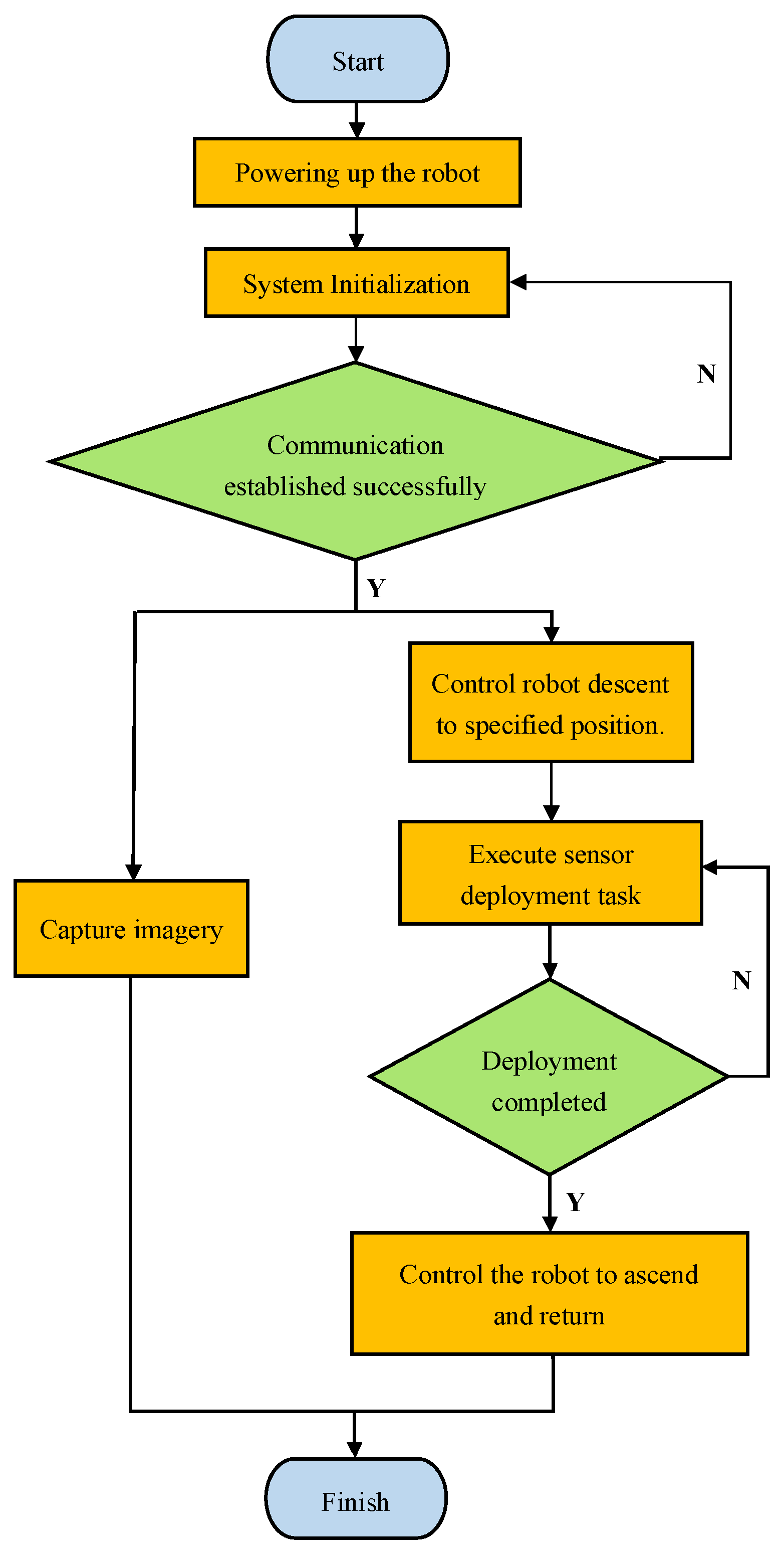
  • The design and construction of the bionic marine iguana robot are completed, and its feasibility is verified through performance testing. The robot demonstrates excellent motion sensitivity and can perform underwater environmental detection and micro-sensor deployment tasks, providing an innovative solution for micro-sensor deployment in marine military applications.
The structure of this paper is as follows: Section 2 introduces the biological structure of the marine iguana and the mechanical structure design of the bionic marine iguana robot; Section 3 presents the control system design of the robot; Section 4 establishes a kinematic model based on the locomotion characteristics of marine iguanas and conducting kinematic analysis for gait planning of a bionic marine iguana robot; Section 5 tests the robot’s performance through underwater crawling, swimming, and sensor deployment experiments, verifying the effectiveness of the control system; Section 6 discusses and summarizes the paper.

2. Mechanical Structure Design of the Bionic Marine Iguana Robot

2.1. Overall Structure Design

The marine iguana is a unique marine reptile, the only lizard adapted to marine life [13]. It can crawl slowly on land and has excellent swimming and diving abilities. Its flat tail and strong limbs are the main sources of propulsion, allowing it to swim flexibly and dive quickly through coordinated body movements.
As shown in Figure 1, the marine iguana consists of a head, body, legs, and tail. Based on the marine iguana’s biological structure, a bionic marine iguana robot is designed. The robot’s structure, shown in Figure 2, includes a head deployment mechanism, underwater crawling mechanism, tail swimming mechanism, and buoyancy adjustment mechanism. The head deployment mechanism is used for precise sensor deployment, the underwater crawling mechanism allows the robot to move on the seabed, and the tail swimming mechanism simulates the marine iguana’s tail movement to provide propulsion. The buoyancy adjustment module consists of a center of gravity adjustment mechanism, which changes the robot’s buoyancy by adjusting its center of gravity. The mechanical structure is designed using SolidWorks 2021 and manufactured using 3D printing; the head-mounted sensor deployment mechanism requires frequent rotation and therefore utilizes a POM material characterized by high rigidity and a low coefficient of friction. The crawling mechanism must support the entire body weight and withstand direct ground contact, thus employing ABS material, known for its high strength, toughness, and wear resistance. For all other components without specific requirements, PLA material was selected for its cost-effectiveness and ease of printing [14], with appearance parameters shown in Figure 2 and Table 1.

2.2. Design of Deployment Mechanism

The robot’s precise sensor deployment is primarily achieved by the head deployment mechanism, assisted by the amphibious crawling mechanism and the body’s buoyancy adjustment mechanism. The head deployment mechanism consists of a servo motor, cross flange, plug cover, and a rotating plug with eight special blades, as shown in Figure 3. Prior to deployment, the plug cover is opened for loading of micro-sensors and then securely closed, with the rotating plug in the initial position tightly fitted to the cover to prevent sensor leakage. After loading, the robot enters the water, swims close to the target area, sinks to land on the seabed, and crawls close to the target using the crawling and buoyancy adjustment mechanisms. Once the optimal deployment position is reached, the head rotating plug is driven by the servo motor through the cross flange, rotating to deploy the micro-sensors through the cover’s lower hole, achieving precise sensor node placement. The robot then moves to other target areas or returns. When all eight chambers’ micro-sensors are deployed, a work cycle is completed. The carousel-type deployment mechanism designed in this study offers advantages including multi-point deployment capability, stable release, and simple structure. However, issues such as its fixed deployment sequence and susceptibility to port clogging still require optimization.

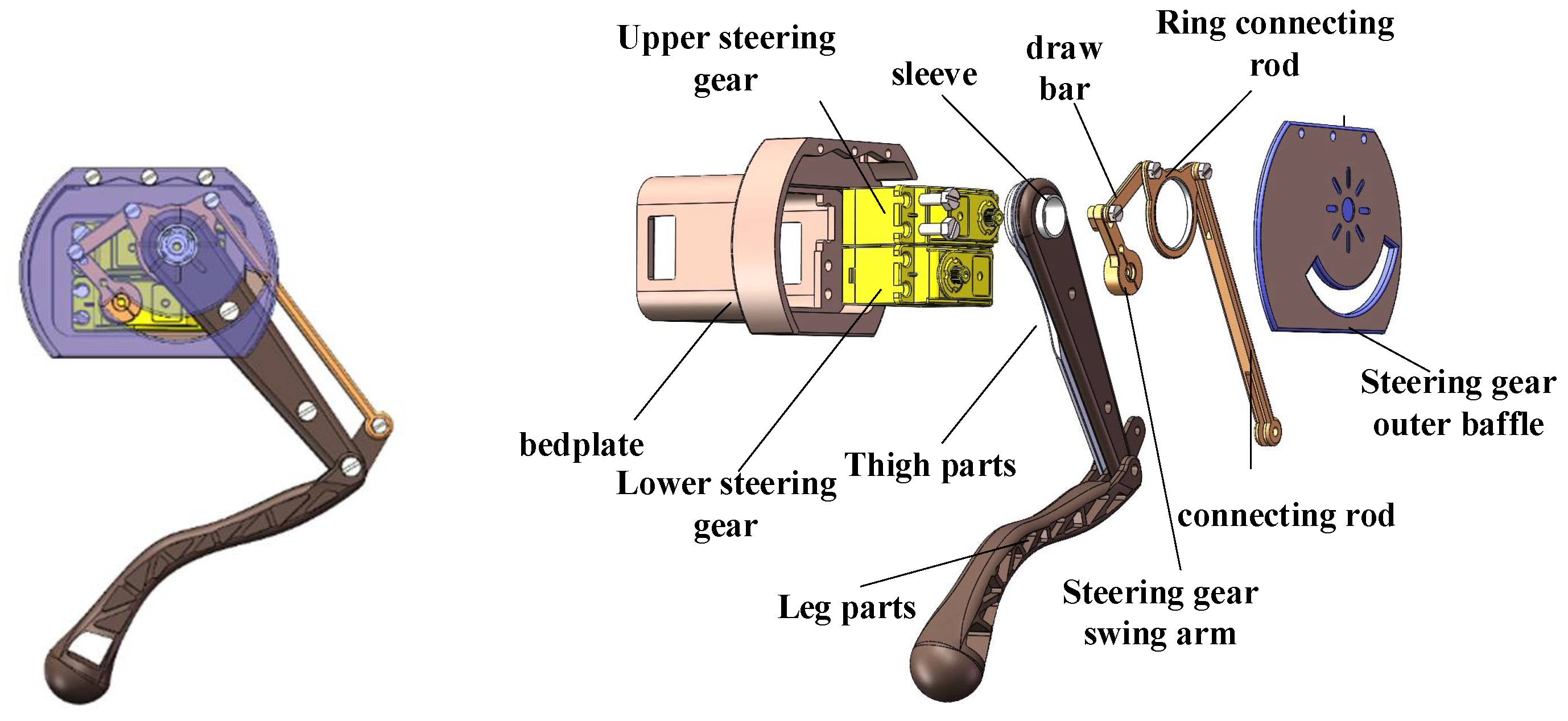
2.3. Design of Crawling Mechanism

The bionic marine iguana robot mimics the marine iguana’s terrestrial walking state using a quadruped mechanism. The four legs are of equal size and consist of servo motors, four-bar linkage mechanisms, thigh components, calf components, and shells. The thigh and calf components form a 2-degree-of-freedom mechanical arm, with the thigh directly driven by the servo motor and the calf indirectly driven through the four-bar linkage. This design reduces the leg’s redundant weight, improving motion efficiency. During swimming, the legs retract to minimize contact with obstacles and reduce swimming resistance. The crawling design effectively addresses the obstacle-crossing challenges faced by amphibious robots on land [15], offering a new solution for amphibious robot obstacle avoidance. The leg mechanism model is shown in Figure 4.

2.4. Design of Swimming Mechanism

The tail propulsion system of the biomimetic marine iguana robot achieves underwater locomotion by simulating the undulatory propulsion mechanism of the marine iguana’s tail. As shown in Figure 5, the system primarily consists of articulated elliptical plates, nylon cords, a spring-based vertebral column, and a servo motor. The spring vertebral column serves as the flexible backbone of the tail, while the series of elliptical plates mimic the segmented structure of the marine iguana’s tail. The bilateral nylon cords connect to a dual-output crank arm driven by the servo motor, forming a cable–spring coupled undulatory transmission system.
When the servo motor drives the crank arm to perform periodic reciprocating rotation, the alternating tension and relaxation of the bilateral nylon cords induce lateral bending deformation in the spring vertebral column. This causes sequential oscillation of the articulated plates, generating sinusoidal undulatory waves that propagate from the tail base to its tip. This undulatory motion generates thrust by altering water momentum: when the tail swings to one side, the hydrodynamic reaction force acting on the plates propels the robot in the opposite direction. By adjusting the servo’s rotational frequency and crank arm amplitude, both the undulation frequency and amplitude of the tail can be controlled, thereby regulating the robot’s swimming speed and turning angle.
This innovative design transforms the servo’s rotary motion into tail undulation through the coupling effect of flexible springs and rigid articulated plates. It not only preserves the propulsion efficiency of the marine iguana’s tail but also reduces mechanical complexity through its modular architecture.

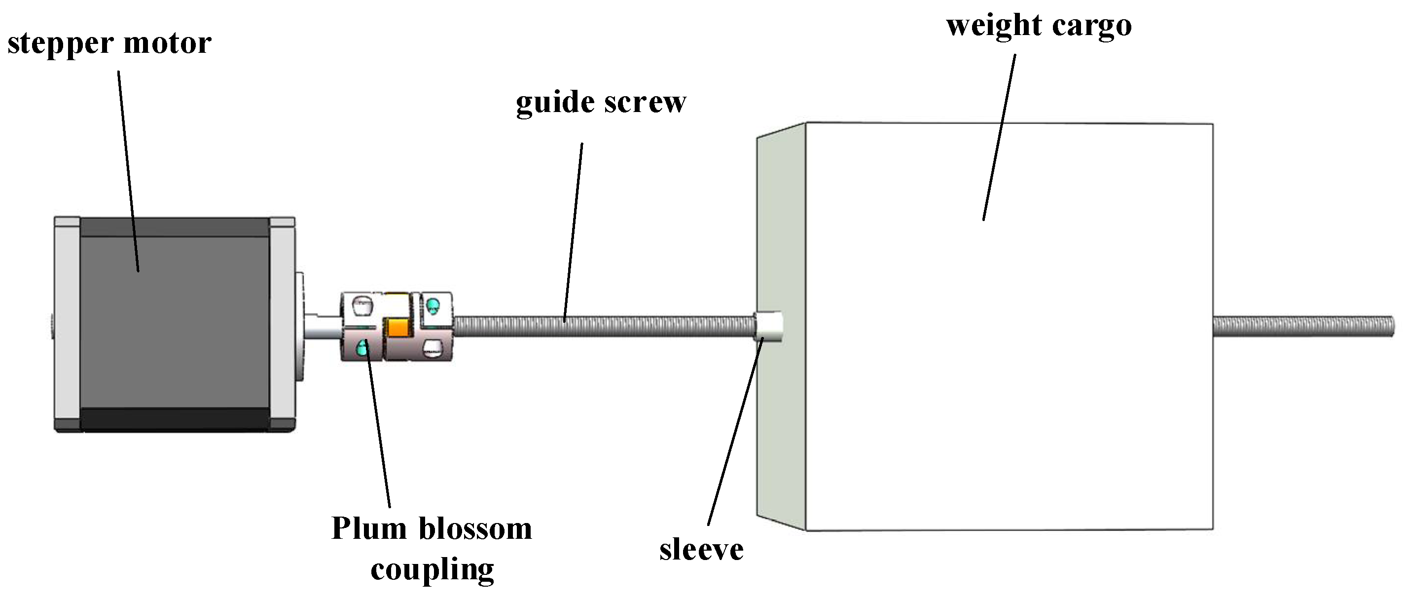
2.5. Design of Buoyancy Adjustment Mechanism

Small submersibles predominantly utilize propeller-based buoyancy control systems. Although compact in size, these systems suffer from high energy consumption and are susceptible to hydrodynamic counter-torque effects generated by thrusters. In contrast, large submersibles typically employ compressed gas variable ballast systems. Such systems enable precise depth regulation through buoyancy adjustment while maintaining superior attitude stability with relatively lower power requirements. However, their operational limitations include significant volumetric footprint and potential resonance excitation during compressor activation [16].
Through observations of the marine iguana’s swimming postures during ascent and descent, it was found that when ascending, the body tilts upward, with tail oscillations providing upward thrust; conversely, during descent, the body tilts downward, with tail movements generating downward-oriented propulsion.
To integrate the advantages of conventional submersible systems while mimicking the marine iguana’s buoyancy control, this design incorporates a buoyancy adjustment unit located in the robot’s abdominal region. This unit operates synergistically with tail motion to achieve depth changes. The mechanism comprises a center-of-gravity adjustment assembly, including components such as a motor, lead screw, and weight cargo (see Figure 6). The specific operational process is as follows: by driving the motor forward, the robot’s weight moves towards its head direction to achieve a downward posture while shifting its center of gravity forward; subsequently, with assistance from tail swing power, the robot dives. Conversely, when the weight shifts towards its tail direction causing the robot’s center of gravity to move backward, its head moves upward. By utilizing tail power again, the robot floats up. Furthermore, real-time feedback on body posture information from an attached gyroscope aids in coordinating control for maintaining proper lifting postures underwater while continuous swimming is achieved through a tail swimming mechanism.

2.6. Motor Selection

As critical actuators for the marine iguana-inspired robot, proper motor selection is crucial for enhancing key performance indicators such as motion stability and energy efficiency. As detailed in the Motor Specification Comparison Table 2, we compared the specific parameters of five candidate motors, including waterproof performance, torque, weight, power, and price. The TD-9420MG servo was selected for quadrupedal joint actuation due to its sufficient torque, excellent waterproofing, moderate cost, and direct PWM control compatibility via the STM32 microcontroller. The 42-series stepper motor was chosen for the head-mounted deployment mechanism, as it offers cost-effectiveness, meets the required control precision, and fulfills the demands for intermittent positioning operations. Consequently, this study employs the TD-9420MG servo motor for limb joints and the 42-series stepper motor for buoyancy adjustment weight positioning.

3. Control System Design of the Bionic Marine Iguana Robot

3.1. Hardware System Design

The control system includes a control drive module, image acquisition module, remote communication module, and buoyancy adjustment module.
The control drive module is responsible for completing the motion control and driving of the robot. It is composed of the core controller STM32, TD-9420MG underwater servos [17], 42 stepper motors [18], etc. The servo drive board is built around the PCA9685 core, featuring 12-bit resolution and capable of outputting multiple PWM pulses to drive the waterproof servos, thereby controlling the leg movements of the bionic marine iguana robot. The motor drive controls the stepper motors to adjust the lead screw position, enabling the robot system to ascend or descend. The image acquisition module consists of a camera module and a data acquisition and processing module, with the OpenMv camera module responsible for capturing image information during the robot’s underwater operations, allowing operators to achieve precise control through real-time transmitted images. The remote communication module employs an RS485 bus-based remote control system [19], primarily responsible for transmitting commands from the external host computer to the robot system [20], enabling remote control and human–machine interaction for the bionic marine iguana robot. The peripheral sensing module encompasses various components such as water level sensors for detecting water depth, underwater ultrasonic sensors for obstacle voidance, temperature sensors, and gyroscopes. Collected data on water depth, accessibility, temperature, and attitude angles are processed by an STM32 master before being transmitted to upper computer software for display purposes. The structural relationship is shown in Figure 7.

3.2. Software System Design

In addition to the aforementioned hardware design, the corresponding software system design is also of paramount importance. The software control process of the bionic marine iguana robot system is shown in Figure 8: First, the robot system undergoes power-on and initialization procedures. Following this, the upper computer control software is initiated, and wireless communication is successfully established. Once connected, the system executes its own module program. The operator then controls the robot to descend to a designated position through the control terminal, carrying out precise sensor delivery tasks before commanding it to resurface at another specified location upon task completion. Throughout this entire process, real-time information such as water level, temperature, attitude angle, and live imagery is transmitted to the control terminal via a communication module, enabling operators to monitor both working conditions and operational status.

4. Gait Planning and Kinematic Analysis of the Bionic Marine Iguana Robot

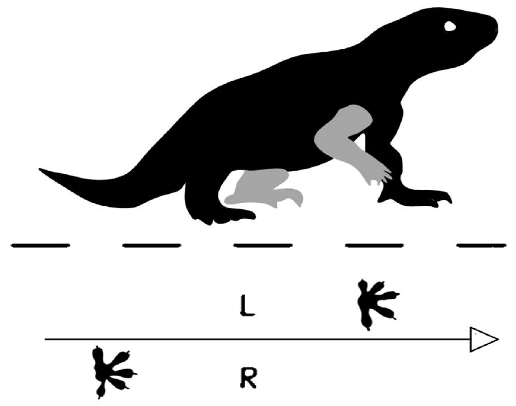
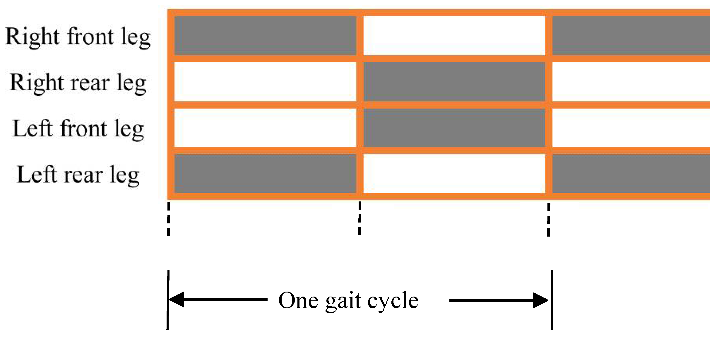
4.1. Crawling Gait Planning

According to the locomotion characteristics of quadrupedal animals, gait planning [20,21,22] is performed for the bionic marine iguana robot. Typically, quadruped robots exhibit five primary gaits: walk gait, trot gait, pace gait, gallop gait, and bound gait.
The walk gait is a static gait in which at least three legs remain in contact with the ground during locomotion, forming the support phase [23]. The robot’s center of mass lies within the convex polygon formed by the supporting legs, ensuring high stability but at the cost of low forward speed. In contrast, the trot gait is a typical dynamic gait, where diagonal leg pairs alternate between support and swing phases. This configuration provides inherent dynamic symmetry, effectively counteracting unbalanced moments on the quadruped robot, thereby achieving high dynamic stability [24]. However, the trot gait is less suitable for rapid turning or speed adjustments. Compared to other gaits, the trot exhibits relatively lower stability and requires more complex control algorithms. Nevertheless, it offers higher locomotion speed and superior environmental adaptability, making it a widely studied gait in recent years. Considering the performance requirements of the iguana-inspired robot in this study, the trot gait was selected as the primary locomotion mode, balancing speed and stability. Figure 9 illustrates the schematic of the trot gait.
The trot gait, also referred to as the diagonal running gait, divides its gait cycle into swing and support phases. For clarity, the duty cycle is introduced to characterize the robot’s gait [25], defined as the ratio of the swing phase duration to the entire gait cycle for each leg. As illustrated in Figure 10, the gray shaded areas indicate the period during which the limbs are in contact with the ground, with a duty cycle of 0.5, the bionic marine iguana robot initiates movement with the right foreleg and left hind leg in the support phase. Subsequently, the right hind leg and left foreleg transition into the support phase, while the right foreleg and left hind leg enter the swing phase, thereby completing one full gait cycle. The schematic diagram of leg state change of trot gait robot is shown in Figure 11, the arrows indicate the direction of motion.

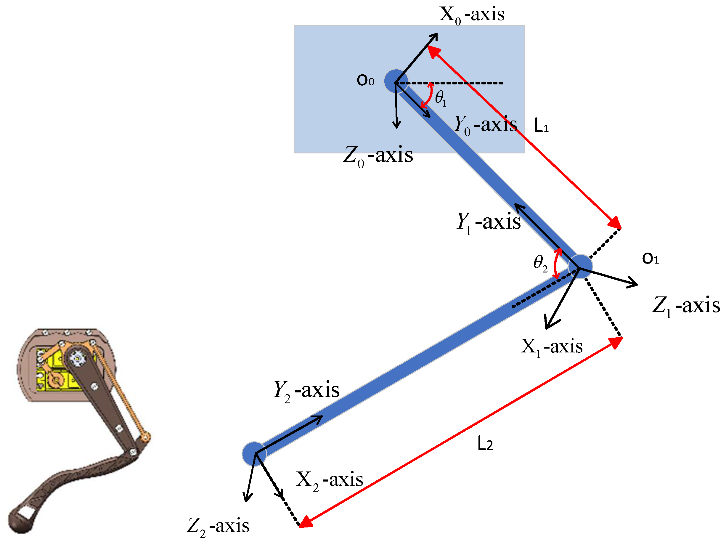
4.2. Leg Kinematic Modeling

The D-H coordinate system for a single leg of the bionic marine iguana robot was established, as shown in Figure 12. The D-H parameters for the robotic leg were designed and are presented in Table 3. The bionic quadruped robot in this study features two degrees of freedom per leg, comprising a hip joint and a knee joint, whose coordinated movement enables basic gait implementation. L1 and L2 are 100 mm and 120 mm, respectively. By substituting the parameters from Table 3 into the general homogeneous transformation matrix formula, the adjacent coordinate system transformation matrices T 0 1 , T 1 2 , and T 2 3 were derived as follows:
T 0 1 = c o s θ 1 s i n θ 1 0 0 s i n θ 1 c o s θ 1 0 0 0 0 1 0 0 0 0 1
T 1 2 = c o s θ 2 s i n θ 2 0 L 2 s i n θ 2 c o s θ 2 0 0 0 0 1 0 0 0 0 1
T 2 3 = 1 0 0 L 2 0 1 0 0 0 0 1 0 0 0 0 1
Multiplying these matrices yields a 4 × 4 homogeneous transformation matrix from the base coordinate system { O 0 } to the foot-end coordinate system { O 3 } for a single robotic leg as follows:
T 0 3 = T 0 1 T 1 2 T 2 3 = c o s ( θ 1 + θ 2 ) s i n ( θ 1 + θ 2 ) 0 L 1 c o s θ 1 + L 2 c o s ( θ 1 + θ 2 ) s i n ( θ 1 + θ 2 ) c o s ( θ 1 + θ 2 ) 0 L 1 s i n θ 1 + L 2 s i n ( θ 1 + θ 2 ) 0 0 1 0 0 0 0 1
From the above equation, the forward kinematic equation of the robot’s single leg can be obtained:
x = L 1 c o s θ 1 + L 2 c o s ( θ 1 + θ 2 ) z = L 1 s i n θ 1 + L 2 s i n ( θ 1 + θ 2 )
The above equation contains few variables. By directly solving it, the inverse kinematics equation of the robot’s single leg can be obtained:
θ 1 = a   t a n 2 x L 1 + L 2 c o s θ 2 + z L 2 s i n θ 2 z L 1 + L 2 c o s θ 2 x L 2 s i n θ 2 θ 2 = 2 a   t a n 2 ( L 1 + L 2 ) 2 ( x 2 + z 2 ) ( x 2 + z 2 ) ( L 1 L 2 ) 2

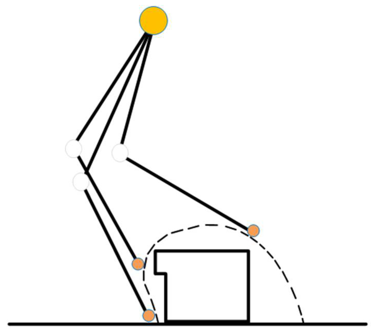
4.3. Crawling Trajectory Planning

When shuttling between aquatic and terrestrial environments, the bionic marine iguana robot inevitably traverses complex terrains, including gravel grounds and muddy seabeds, necessitating trajectory planning for crawling [26,27]. By mimicking the limb retraction behavior of sea iguanas walking through mud, this section proposes a segmented composite foot-end trajectory. As shown in Figure 13,the trajectory divides the foot-end motion into two phases—retraction and stride—to enhance the robot’s mobility on muddy and gravel-covered surfaces. Specifically, the P 2 P 3 segment follows a composite cycloid equation, the P 1 P 2 segment is designed using a fifth-order polynomial equation, and the P 0 P 1 segment represents the reverse motion of the terminal portion of the P 2 P 3 segment.
As shown in Figure 14, the retracted tibia avoids collisions between the foot and gravel when traversing rocky terrain. In Figure 15, when the foot sinks deeply into mud, the tibia retracts along the planned trajectory to disengage from the viscous resistance.
To minimize motion impact and ensure smooth transitions between trajectory segments, the velocity and acceleration must be equal at all connecting points. Additionally, both the liftoff and touchdown instants require zero velocity and acceleration. The following boundary conditions are derived from segmentation and splicing of the composite cycloid trajectory:
x 0 = 10 ,   x ˙ 0 0 = 0 ,   x ¨ 0 0 = 0 z 0 = 0 ,   z ˙ 0 0 = 0 ,   z ¨ 0 0 = 0 x 1 T w 5 = 7.56827 ,   x ˙ 1 T w 5 = 34.5492 ,   x ¨ 1 T w 5 = 298.783 z 1 T w 5 = 5.18237 ,   z ˙ 1 T w 5 = 44.8175 ,   z ¨ 1 T w 5 = 91.4963 x 2 3 T w 10 = 7.43173 ,   x ˙ 2 3 T w 10 = 65.4508 ,   x ¨ 2 3 T w 10 = 298.783 z 2 3 T w 10 = 9.81763 ,   z ˙ 2 3 T w 10 = 44.8175 ,   z ¨ 2 3 T w 10 = 91.4963 x 3 ( T w ) = 50 ,   x ˙ 3 T w = 0 , x ¨ 3 T w = 0 z 3 ( T w ) = 0 ,   z ˙ 3 T w = 0 , z ¨ 3 T w = 0
The piecewise trajectory function is derived from the constraint conditions through computational analysis:
X ( t ) = S 1 t 1 2 π s i n [ 2 ( 1 t ) π ]         0 t < T m 5 7.56 34.55 t 0.2 149.35 t 0.2 2 840.54 ( t 0.2 ) 3 + 127550 ( t 0.2 ) 4 710190 ( t 0.2 ) 5 T m 5 t < 3 T m 10 S [ t 1 2 π s i n ( 2 t π ) ] 3 T m 10 t < T m
Y ( t ) = H 1 2 1 2 c o s [ 2 ( 1 t ) π ]         0 t < T m 5 5.18 + 44.82 t 0.2 + 45.75 t 0.2 2 294.83 ( t 0.2 ) 3 + 152.43 ( t 0.2 ) 4 + 609.70 ( t 0.2 ) 5 T m 5 t < 3 T m 10 H [ 1 2 1 2 c o s ( 2 t π ) ] 3 T m 10 t < T m
We set the foot trajectory step length S to 40 mm and the leg lift height H to 5 mm. The swing phase duration Tm = 1 s, and the complete gait cycle T = 2Tm. The trajectory equations were implemented in MATLAB R2023a, yielding the forward displacement curve, vertical displacement curve, forward velocity curve, and vertical velocity curve as shown in Figure 16, Figure 17, Figure 18 and Figure 19. Both displacement and velocity curves exhibit smooth profiles without abrupt variations. The complete trajectory curve is presented in Figure 20. Figure 16 and Figure 17 display the foot-end displacement characteristics of the robot during a complete gait cycle. The continuity and smoothness of the curves reflect natural spatial transitions in the foot-end trajectory, with no abrupt changes or jumps, demonstrating the system’s effective tracking of gait trajectories. In the forward motion curve (Figure 17), the position coordinate measures 10 mm at T = 0 and 7 mm at T = 0.25, illustrating the robot’s imitation of the marine iguana’s hind leg lifting motion. Figure 18 and Figure 19 present corresponding velocity curves, exhibiting both smoothness and periodicity. Both forward and vertical velocities display continuous and differentiable curve trends. This characteristic corresponds to natural biological movement: biological gaits avoid high-frequency vibrations or sudden accelerations, instead transitioning rhythmically to optimize energy consumption and stability. These curves thus effectively support biomimetic rationality. Figure 20 depicts the robot’s end-effector trajectory during a complete swing phase, forming a clear and controllable curve in two-dimensional space. This trajectory design emulates natural limb movements during toe-off and touchdown in gravel or muddy terrain. Through segmented composite function control, we regulate the foot-end path to incorporate four transitional phases: leg lifting, retracting, propulsion, and touchdown buffering, further enhancing biomimetic consistency.

4.4. Swimming Posture Planning

The swimming posture of the robot in the horizontal plane is planned [28,29,30]. Before swimming begins, the quadruped limbs are retracted to minimize drag. The rotation of the dual-output crank arm on the servo motor alternately tightens or loosens the two nylon cords at the base, causing the tail to swing laterally from the root, thereby generating forward propulsion.
To more clearly illustrate the swimming process, Figure 21 demonstrates the four state changes of the tail during one motion cycle:
In the initial stage, the crank arm is centered with the spring backbone undeformed and joint plates aligned linearly.
During the right-swing stage, the crank arm rotates counterclockwise to tighten the right nylon cord, causing the spring backbone to bend rightward and the joint plates to sequentially swing right, forming a rightward undulatory wave.
The reset stage sees the crank arm return to the neutral position with elastic recovery of the spring backbone to the initial state.
In the left-swing stage, clockwise rotation of the crank arm tightens the left nylon cord, bending the spring backbone leftward and making the joint plates swing left sequentially to form a leftward undulatory wave.

4.5. Swimming Kinematic Analysis

An analysis was conducted on the swimming kinematics of the bionic marine iguana robot’s tail [31], with specific parameters of the tail section shown in Figure 22. There exists a linear relationship between the variation value q of the nylon cord outside the casing and the oscillation amplitude d y of each point on the tail, approximated as d y = k × q . Based on the mechanism’s characteristics, geometric analysis, and algebraic calculations, the formula for the variation of the tail tip’s oscillation amplitude over time was derived as follows:
d y = k × q = k [ D D cos ( ω t ) ] 2 [ D sin ω t + h ] 2
In the equation, the servo rotation angular velocity ω = 2 π / s ; the proportionality coefficient between amplitude and servo rotation angular velocity k = 10 ; the distance from the double-headed rocker arm to the tail root h = 43   m m ; the distance from the center of the double-headed rocker arm to both ends D = 10   m m . The calculated variation function graph of tail oscillation amplitude with time is shown in Figure 23.
The primary mechanism for thrust generation in the bionic marine iguana robot’s tail lies in altering water flow velocity and direction through tail oscillations. The tail’s motion can be characterized as periodic. This paper proposes dividing the robotic tail into n segments, establishing kinematic equations for each segment, and ultimately developing a segmented tail dynamics model through coupled deformation-dynamics iteration.
To simplify calculations, the influence of tail shape is neglected. As illustrated in Figure 22, the dynamic coordinate system is established with the origin X 0 Y 0 Z 0 at the tail base where it connects to the robot body. The tail is uniformly divided into n segments, each of length l n = L n . A local coordinate system is defined for each segment, where system X 1 Y 1 Z 1 coincides with the base frame, and all segment coordinate origins align along the tail’s central axis.
When oscillating laterally in water, the robotic tail experiences hydrodynamic resistance. In our simplified model, this resistance induces tail deformation. The deflection equation describing the angular velocity and deformation angle of the n th tail segment in its local coordinate system is expressed as follows:
ω n = F w n x 2 6 E I ( 3 l x )
θ B n = F w n l 2 3 E I
where F w n is the hydrodynamic resistance acting on the tail, with its direction opposite to the tail’s oscillation direction, expressed as follows:
F w = 1 2 C T ρ v x 2 S = 1 2 C T ρ ( ω 0 · l ) 2 S
Here, C T   is the hydrodynamic coefficient, taken as 1 in this study; ρ is the density of water at 20 °C, set at 998.21   k g / m 3 ; S is the contact area between the section and water.
Calculating the iterative process within one time differential segment d t : since the deformation of the tail root is neglected, the formula for the tail-end swing amplitude variation over time Equation (10) is given by the following:
P t e = h × cos θ 0 t , h × sin θ 0 t
Here, the real-time angle of the tail root end, θ 0 t , can be expressed as follows:
θ 0 t = 0 t ω t d t
Based on the above equations, the deformation deflection and hydrodynamic calculations are sequentially performed for each differential tail segment, and the hydrodynamic forces acting on each segment are computed through coupled iteration as follows:
f n _ n = m n l c n ω n l c n + F w n c o s ( θ n ) 0 F w n s i n ( θ n )
Finally, based on the robot’s internal propulsion equations, the resultant hydrodynamic force acting on the tail end is calculated as follows:
f 0 _ 0 = F x 0 0 F Z 0 = R 1 1 0 f 1 + m 0 l c 0 0 0 × 0 ω 0 l c 0 0 + F w 0 c o s ( θ 0 ) 0 F w 0 s i n ( θ 0 )
During the swimming motion of the bionic marine iguana robot, F x 0   represents the propulsive force exerted on the main body by the entire tail. By substituting the tail design parameters into the calculations, the propulsive force curve of the tail swimming mechanism shown in Figure 24 can be obtained. The results indicate that during the stable motion phase, the maximum propulsive force generated by the bionic marine iguana robot is 3.954   N , while the minimum value is 3.141   N .
To calculate the swimming speed of the bionic marine iguana robot, it is also necessary to compute the total hydrodynamic drag force   F D acting on the robot body, which is expressed as follows:
F D = 1 2 C D ρ S D v 2
Here, C D   is the drag coefficient, taken as 0.6 in this study; S D   represents the frontal area of the bionic marine iguana robot, with a value of 0.026   m 2 .
According to Newton’s Second Law, the robot’s acceleration is determined by the net force acting upon it:
F x 0 F D = m d v d t
Since this equation constitutes a complex nonlinear system, the Euler method is employed here for numerical solution of the differential equation. The update formula of the Euler method is expressed as follows:
v n + 1 = v n + d v d t t
After the update iteration, the velocity curve of the tail swimming mechanism shown in Figure 25 can be obtained. The results indicate that the maximum swimming speed of the bionic marine iguana robot reaches 0.196   m / s .

5. Performance Testing of the Bionic Marine Iguana Robot

5.1. Basic Function Testing

The primary function test section primarily assesses the normal operation of system functions. Before testing, a thorough examination of the robot’s appearance and waterproofing is conducted. At the commencement of the test, the robot is powered on, ensuring proper initiation and termination of operations. Upon startup, the power indicator illuminates, signaling the initiation of system functionality; upon shutdown, the power indicator extinguishes, indicating the cessation of system operations.
Next, an assessment of normal land movements is conducted. The rocker controls are used to facilitate forward and backward motion as well as left and right turns, ensuring that these actions align with expected behaviors. Finally, an evaluation of operational capabilities in aquatic environments is performed. Pressing the corresponding buttons allows for the seamless execution of actions such as floating up, diving down, and head rotation. The bionic marine iguana robot is shown in Figure 26.

5.2. Underwater Crawling Test

The crawling performance test primarily evaluates stability, speed, and response time during locomotion. The robot was controlled to initiate movement, and its motion trajectory was recorded, showing basic agreement with theoretical predictions. Ten separate energy consumption tests were conducted for the crawling state. The measured average underwater crawling speed was 0.14 m/s, average power consumption was 12.4 W, and energy efficiency was 11.3 m/Wh. Environmental factors significantly affected communication quality; however, response times remained within 0.5 s during both laboratory and riverside testing scenarios. The images in Figure 27 show the underwater crawling process.

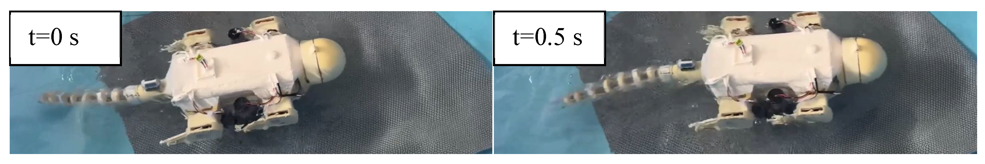
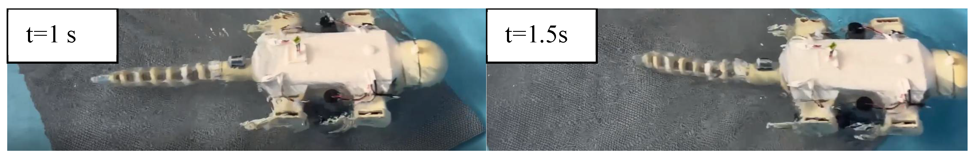
5.3. Underwater Swimming Test

The swimming performance test primarily evaluates stability, speed, and response time during aquatic locomotion. The robot successfully executed multiple controlled ascents and descents, with its swimming gait remaining within theoretically planned parameters. When operating at depths around 20   c m , the system demonstrated reliable performance with no water ingress.
Through repeated measurements in a static water laboratory environment, the robot’s average underwater swimming speed was 0.196 m/s, average power consumption was 10.1 W, and energy efficiency was 19.3 m/Wh. As swimming distance increased, the presence of more obstacles and signal attenuation resulted in marginally longer response times. The images in Figure 28 show the underwater swimming process.

5.4. Sensor Deployment Testing

The head deployment performance test primarily evaluates the robot’s stability, accuracy, and response time during payload release operations. After navigating the robot to the designated underwater position, the deployment sequence is initiated. Upon pressing the release button, the system demonstrates a response time of approximately 0.7   s , indicating satisfactory real-time performance. In a total of 40 deployment experiments, the head-mounted deployment mechanism achieved an average placement error of 3.8 cm, a maximum error of 6.8 cm, and a success rate of 77.5% (error < 5 cm). While the overall performance was satisfactory, jamming of the rotary latch occurred during initial testing. This issue was mitigated by improving machining tolerances and applying lubricant, with no recurrence observed in subsequent trials. These results validate the stability and practicality of the deployment system. The images in Figure 29 show the process of the robot deploying sensors underwater.

5.5. Theoretical and Experimental Data Comparative Analysis

To validate the accuracy of the kinematic and propulsion models proposed in Chapter 3, this section presents a quantitative comparison between theoretical predictions and experimental measurements. The results are summarized in Table 4, which includes key performance metrics such as maximum thrust force, average swimming speed, and undulation frequency, along with their corresponding error analyses.
According to the quantitative comparison in Table 4, the model predicted a maximum thrust of 4.21 N, while experimental results yielded 3.954 N, resulting in an absolute error of 0.256 N (RMSE = 0.18, R2 = 0.92). Similarly, the theoretical prediction for average swimming speed was 0.22 m/s compared to the experimental value of 0.196 m/s, with an absolute error of 0.024 m/s (RMSE = 0.03, R2 = 0.88). The theoretical undulation frequency was 1.5 Hz, whereas the actual measured frequency was 1.2 Hz, leading to an absolute error of 0.3 Hz (RMSE = 0.25, R2 = 0.85).
Through team analysis, the discrepancies between theoretical and experimental results can be attributed to the following factors:
  • Unmodeled Fluid Dynamics
The theoretical framework simplified hydrodynamic interactions, neglecting vortex shedding and turbulence effects around the tail base. These unaccounted fluid dynamic factors resulted in a 6.1% underestimation of thrust (0.256 N error).
  • Mechanical Efficiency Losses
Energy dissipation in the transmission system, including servo motor inefficiency and friction in joint mechanisms, caused a 12% reduction in swimming speed. This explains the 0.024 m/s deviation.
  • Elastic Deformation of Nylon Cords
The theoretical model assumed ideal rigidity in the actuation system, while actual tests revealed elastic stretching in the nylon cords. This introduced phase delays in undulation, resulting in a 20% frequency discrepancy (0.3 Hz error).
The analysis demonstrates that despite minor deviations, the core kinematic and propulsion models provide a reliable foundation for robot design and control optimization. The high correlation coefficients (R2 ≥ 0.85) confirm the model’s effectiveness in capturing the dominant propulsion mechanisms.
Therefore, future improvements should include the following: (1) computational fluid dynamics (CFD) to enhance hydrodynamic predictions; (2) energy loss modeling for transmission components to better address efficiency issues; and (3) incorporation of viscoelastic properties of drive cables in dynamic analysis. These adjustments will improve prediction accuracy while maintaining the model’s computational efficiency for real-time control applications.

6. Conclusions

This paper takes the marine iguana as the bionic object and has developed a prototype system of the marine iguana-inspired robot based on its motion characteristics. During actual missions, its behavior switching logic is driven in real-time by depth sensors and IMU attitude data and automatically enters a “buffer state” before switching to ensure complete shutdown of the current submodule. In sensor deployment tasks, the system will suspend the main locomotion module, preset buoyancy depth, and perform fine posture adjustments, achieving a closed-loop control process of locomotion–deployment–relocomotion. This significantly improves deployment accuracy and limits cumulative errors. The mechanism provides clear behavioral switching procedures and multi-module coordination logic for system-level operations. The prototype uses a buoyancy regulation unit with adjustable weight position to control ascent/descent during swimming. The designed crawling and swimming gait control methods effectively enhance stability during underwater locomotion, while its specialized foot-end trajectory is suitable for micro-sensor deployment in shallow muddy and gravel beach environments. During testing, although issues arose with the head-mounted sensor deployment device, stable operation was achieved after modifications, enabling basic underwater object placement. The system exhibits excellent motion agility for aquatic environment exploration and micro-sensor deployment, offering a novel approach for sensor deployment in marine military applications. However, the robot still has structural and control limitations, including incomplete self-righting capability, uncontrollable deployment sequence, and complex maintenance. Future research will focus on structural lightweighting, adaptive deployment strategies, and rollover resistance to further enhance the system’s intelligence and practicality.

Author Contributions

Conceptualization, G.C. and X.T.; Methodology, G.C., X.T., B.G., G.L., Z.W., W.H., Y.X. and M.L.; Software, B.G. and G.L.; Formal analysis, G.C., B.G., J.L. and Z.L.; Resources, Z.W.; Data curation, G.L. and W.H.; Writing—original draft, G.C. and X.T.; Writing—review & editing, G.C., X.T., B.G., G.L., Z.W., W.H., Y.X., M.L., J.L. and Z.L.; Supervision, G.C.; Funding acquisition, G.C. All authors have read and agreed to the published version of the manuscript.

Funding

This work was financially supported by National Natural Science Foundation of China (No. 52275037), Zhejiang Provincial Natural Science Foundation of China (No. LR24E050002), the Key Research and Development Project of Zhejiang Province (No. 2024C01257), and the Fundamental Research Funds of Zhejiang Sci-Tech University (No. 24242088-Y).

Data Availability Statement

Data are contained within the article.

Conflicts of Interest

Author Gang Chen was employed by the company Xiangshan Knitting Research Institute Co., Ltd. The remaining authors declare that the research was conducted in the absence of any commercial or financial relationships that could be construed as a potential conflict of interest.

References

  1. Lloret, J. Underwater sensor nodes and networks. Sensors 2013, 13, 11782–11796. [Google Scholar] [CrossRef] [PubMed]
  2. Pompili, D.; Melodia, T.; Akyildiz, I.F. Three-dimensional and two-dimensional deployment analysis for underwater acoustic sensor networks. Ad Hoc Netw. 2009, 7, 778–790. [Google Scholar] [CrossRef]
  3. Luo, J.; Yang, Y.; Wang, Z.; Chen, Y. Localization algorithm for underwater sensor network: A review. IEEE Internet Things J. 2021, 8, 13126–13144. [Google Scholar] [CrossRef]
  4. Felemban, E.; Shaikh, F.K.; Qureshi, U.M.; Sheikh, A.A.; Qaisar, S.B. Underwater sensor network applications: A comprehensive survey. Int. J. Distrib. Sens. Netw. 2015, 11, 896832. [Google Scholar] [CrossRef]
  5. Xu, T.; Yu, J.; Vong, C.-I.; Wang, B.; Wu, X.; Zhang, L. Dynamic morphology and swimming properties of rotating miniature swimmers with soft tails. IEEE/ASME Trans. Mechatron. 2019, 24, 924–934. [Google Scholar] [CrossRef]
  6. Prahacs, C.; Saudners, A.; Smith, M.K.; McMordie, D.; Buehler, M. Towards legged amphibious mobile robotics. In Proceedings of the Canadian Engineering Education Association (CEEA), Montreal, QC, USA, 29–30 July 2004. [Google Scholar] [CrossRef]
  7. Chen, G.; Xue, H.; Meng, X.; Zhao, Z.; Liu, Z. Multi-performance index reinforcement learning training of beaver-like robot. Meas. Sci. Technol. 2025, 36, 036204. [Google Scholar] [CrossRef]
  8. Cao, Y.; Cao, Y.H.; Huang, Q.G.; Qu, Y.L.; Pan, G. A review of the underwater bionic flapping wing robots. Digit. Ocean Underw. Warf. 2023, 6, 380–405. [Google Scholar] [CrossRef]
  9. Gao, A.; Yang, E.H.; Zhang, J.N. Design of Dual-drive Bionic Jellyfish Based on Compliant Mechanism. Digit. Ocean Underw. Warefare 2023, 6, 504–510. [Google Scholar] [CrossRef]
  10. Ahmed, F.; Waqas, M.; Shaikh, B.; Khan, U.; Soomro, A.M.; Kumar, S.; Ashraf, H.; Memon, F.H.; Choi, K.H. Multi-material bio-inspired soft octopus robot for underwater synchronous swimming. J. Bionic Eng. 2022, 19, 1229–1241. [Google Scholar] [CrossRef]
  11. Chen, G.; Xu, Y.; Yang, C.; Yang, X.; Hu, H.; Chai, X.; Wang, D. Design and control of a novel bionic mantis shrimp robot. IEEE/ASME Trans. Mechatron. 2023, 28, 3376–3385. [Google Scholar] [CrossRef]
  12. Guo, S.; Ma, J.; Li, Z.; Zhang, J. Design and swimming test of myliobatid-inspired robot. Chin. J. Ship Res. 2022, 17, 139–144. [Google Scholar] [CrossRef]
  13. Berry, K.A.; Muñoz-Pérez, J.P.; Vintimilla-Palacios, C.P.; Clemente, C.J. Morphological and performance modifications in the world’s only marine lizard, the Galápagos marine iguana, Amblyrhynchus cristatus. Biol. J. Linn. Soc. 2021, 133, 68–80. [Google Scholar] [CrossRef]
  14. Chen, G.; Xu, Y.; Wang, Z.; Hu, H.; Wu, C. Motion stability analysis of beaver-like robot. Proc. Inst. Mech. Eng. Part M: J. Eng. Marit. Environ. 2025, 1–14. [Google Scholar] [CrossRef]
  15. Wang, H.; Yin, Q.; Song, Z.; Shang, J.; Luo, Z. Structure design of a novel self-adaptive climbing mechanism for the amphibious bionic robot. In 2020 Chinese Automation Congress (CAC); IEEE: Piscataway, NJ, USA, 2020; pp. 3519–3522. [Google Scholar] [CrossRef]
  16. Wang, C.; Liu, H.; Zhang, X.; Huang, C.; Chen, Q. Design and Simulation Analysis of Semi-Active Lifting and Sinking Compensation System. Acad. J. Sci. Technol. 2023, 5, 78–86. [Google Scholar] [CrossRef]
  17. da Cruz, A.L.; Vilela, B.; Klein, W. Morphological and physiological traits of the respiratory system in Iguana iguana and other non-avian reptiles. Zoology 2023, 157, 126079. [Google Scholar] [CrossRef]
  18. Groenhuis, V.; Rolff, G.; Bosman, K.; Abelmann, L.; Stramigioli, S. Multi-axis electric stepper motor. IEEE Robot. Autom. Lett. 2021, 6, 7201–7208. [Google Scholar] [CrossRef]
  19. Vo, C.D.; Dang, D.A.; Le, P.H. Development of multi-robotic arm system for sorting system using computer vision. J. Robot. Control. (JRC) 2022, 3, 690–698. [Google Scholar] [CrossRef]
  20. Zeng, X.; Zhang, S.; Zhang, H.; Li, X.; Zhou, H.; Fu, Y. Leg trajectory planning for quadruped robots with high-speed trot gait. Appl. Sci. 2019, 9, 1508. [Google Scholar] [CrossRef]
  21. Hao, Q.; Wang, Z.; Wang, J.; Chen, G. Stability-guaranteed and high terrain adaptability static gait for quadruped robots. Sensors 2020, 20, 4911. [Google Scholar] [CrossRef]
  22. Yi, S. Reliable gait planning and control for miniaturized quadruped robot pet. Mechatronics 2010, 20, 485–495. [Google Scholar] [CrossRef]
  23. Sun, P.; Gu, Y.; Mao, H.; Chen, Z.; Li, Y. Research on walking gait planning and simulation of a novel hybrid biped robot. Biomimetics 2023, 8, 258. [Google Scholar] [CrossRef] [PubMed]
  24. Chen, J.P.; San, H.J.; Wu, X.; Xiong, B.Z. Structural design and gait research of a new bionic quadruped robot. Proc. Inst. Mech. Eng. Part B: J. Eng. Manuf. 2022, 236, 1912–1922. [Google Scholar] [CrossRef]
  25. Zhang, G.; Wang, C.; Li, B.; Zheng, H. Motion planning of a dual manipulator system for table tennis. In Proceedings of the 12th International Conference IAS-12: Intelligent Autonomous Systems 12, Jeju Island, Republic of Korea, 26–29 June 2012; Springer: Berlin/Heidelberg, Germany, 2013; Volume 2, pp. 335–344. [Google Scholar] [CrossRef]
  26. Wang, Z.; Peng, W.; Zhang, B. Kinematics Analysis and Gait Study of Bionic Turtle Crawling Mechanism. Biomimetics 2024, 9, 147. [Google Scholar] [CrossRef] [PubMed]
  27. Yuan, S.D.; Zhou, Y.J.; Luo, C. Crawling Gait Planning Based on Foot Trajectory Optimization for Quadruped Robot. In Proceedings of the 2019 IEEE International Conference on Mechatronics and Automation (ICMA), Tianjin, China, 4–7 August 2019. [Google Scholar] [CrossRef]
  28. Yuan, S.; Zhou, Y.; Luo, C. Crawling gait planning based on foot trajectory optimization for quadruped robot. IEEE/ASME Trans. Mechatronics 2016, 21, 1711–1719. [Google Scholar] [CrossRef]
  29. Li, Z.; Chao, X.; Hameed, I.; Li, J.; Zhao, W.; Jing, X. Biomimetic omnidirectional multi-tail underwater robot. Mech. Syst. Signal Process. 2022, 173, 109056. [Google Scholar] [CrossRef]
  30. Chen, G.; Xu, Y.; Yang, C.; Yang, X.; Hu, H.; Dong, F.; Zhang, J.; Shi, J. Dynamic modeling and experimental analysis of a novel bionic mantis shrimp robot. J. Field Robot. 2025, 42, 493–509. [Google Scholar] [CrossRef]
  31. Di Santo, V.; Goerig, E.; Wainwright, D.K.; Akanyeti, O.; Liao, J.C.; Castro-Santos, T.; Lauder, G.V. Convergence of undulatory swimming kinematics across a diversity of fishes. Proc. Natl. Acad. Sci. USA 2021, 118, e2113206118. [Google Scholar] [CrossRef]
Figure 1. Biological diagram of the marine iguana.
Machines 13 00505 g001
Figure 2. Model of the bionic marine iguana robot.
Machines 13 00505 g002
Figure 3. Exploded view and assembly diagram of the head structure of the bionic marine iguana robot.
Machines 13 00505 g003
Figure 4. Leg structure of the bionic marine iguana robot.
Machines 13 00505 g004
Figure 5. Tail structure of the bionic marine iguana robot.
Machines 13 00505 g005
Figure 6. Underwater depth adjustment mechanism of the bionic marine iguana robot.
Machines 13 00505 g006
Figure 7. Hardware system architecture diagram.
Machines 13 00505 g007
Figure 8. Overall software system block diagram.
Machines 13 00505 g008
Figure 9. Schematic diagram of the trot gait.
Machines 13 00505 g009
Figure 10. Schematic diagram of the trot gait cycle variation.
Machines 13 00505 g010
Figure 11. Schematic diagram of leg state transitions in the trot gait for the robotic system.
Machines 13 00505 g011
Figure 12. D-H coordinate system of the single leg in the bionic marine iguana robot.
Machines 13 00505 g012
Figure 13. Foot trajectory during walking.
Machines 13 00505 g013
Figure 14. Schematic of leg traversing irregular obstacles.
Machines 13 00505 g014
Figure 15. Schematic of leg locomotion on muddy seabed.
Machines 13 00505 g015
Figure 16. Forward displacement.
Machines 13 00505 g016
Figure 17. Leg-lifting displacement.
Machines 13 00505 g017
Figure 18. Forward velocity.
Machines 13 00505 g018
Figure 19. Leg-lifting velocity.
Machines 13 00505 g019
Figure 20. Swing-phase foot-end trajectory.
Machines 13 00505 g020
Figure 21. Four characteristic tail postures during swimming locomotion.
Machines 13 00505 g021
Figure 22. Simplified diagram of the tail swimming mechanism.
Machines 13 00505 g022
Figure 23. Tail oscillation amplitude variation diagram.
Machines 13 00505 g023
Figure 24. Propulsive force curve of the tail swimming mechanism.
Machines 13 00505 g024
Figure 25. Velocity curve of the tail swimming mechanism.
Machines 13 00505 g025
Figure 26. Prototype of the bionic marine iguana robot.
Machines 13 00505 g026
Figure 27. Underwater crawling test of the bionic marine iguana robot.
Machines 13 00505 g027
Figure 28. Underwater swimming test of the bionic marine iguana robot.
Machines 13 00505 g028aMachines 13 00505 g028b
Figure 29. Underwater sensor deployment test of the bionic marine iguana robot.
Machines 13 00505 g029
Table 1. Imitation marine iguana appearance parameters.
Marine Iguana Robot
Appearance Parameters
Quality (kg) Volume   ( m 3 ) Maximum Length (m)Maximum Width (m)Maximum Height (m)
3.3100.00310.8300.3200.281
Table 2. Motor selection methodology.
Actuator TypeModelWaterproof RatingTorqueWeight (g)Power
(W)
Unit Price
(USD)
Joint Drive ServoTD-9420MGIP6720 k g · c m 942.4 (6 V)11.2
Alternative Option 1MG996RIP5415 k g · c m 551.8 (6 V)4.2
Alternative Option 2HiwonderIP6830 k g · c m 1803.6 (12 V)21.1
CG Adjustment Motor42-series Stepper MotorIP664 N · m 28010.2 (6 V)7.0
Alternative OptionNEMA 17 Servo MotorIP653 N · m 32014.4 (12 V)16.9
Table 3. D-H modeling parameters of the single leg.
i L i 1 a i 1 d i θ i The Range of Values of Joint Variables
1000 θ 1 0~180
2 L 1 900 θ 2 0~270
3 L 2 000--
Table 4. Theoretical and experimental data comparative analysis.
ParameterTheoreticalExperimentalAbsolute ErrorRMSER2Primary Error Sources
Tail Max Thrust (N)4.213.9540.2560.180.92Unmodeled vortex shedding
Avg. Speed (m/s)0.220.1960.0240.030.8812% mechanical efficiency loss
Undulation Freq. (Hz)1.51.20.30.250.85Elastic deformation of nylon cords
Disclaimer/Publisher’s Note: The statements, opinions and data contained in all publications are solely those of the individual author(s) and contributor(s) and not of MDPI and/or the editor(s). MDPI and/or the editor(s) disclaim responsibility for any injury to people or property resulting from any ideas, methods, instructions or products referred to in the content.

