Article

Contour Error Control for a Hybrid Robot Equipped with Grating Sensors

by
Xianlei Shan
*,
Tianyu Zou
,
Haitao Liu
,
Yu Deng
and
Juliang Xiao
Key Laboratory of Mechanism Theory and Equipment Design of Ministry of Education, Tianjin University, Tianjin 300354, China
*
Author to whom correspondence should be addressed.
Machines 2025, 13(6), 502; https://doi.org/10.3390/machines13060502
Submission received: 14 April 2025 / Revised: 3 June 2025 / Accepted: 5 June 2025 / Published: 9 June 2025
(This article belongs to the Section Robotics, Mechatronics and Intelligent Machines)

Abstract

To mitigate the detrimental effects of joint elasticity and transmission errors on contour accuracy and to improve the multi-axis motion performance of hybrid robots, this study investigates contour error modeling and control by leveraging additional grating sensors for real-time measurements. Accounting for the inherent pose coupling characteristics of hybrid robots, a novel contour error modeling method is proposed that employs six-dimensional exponential coordinates for error description and incorporates an efficient search algorithm for foot point determination. Building upon an existing grating sensor feedback control framework, a proportional contour controller is developed. Experimental validation on the TriMule-200 hybrid robot demonstrates an enhancement in end-effector contour accuracy.

1. Introduction

A hybrid robot is a high-performance industrial robot that consists of a 1T2R (T—translation; R—rotation) parallel mechanism and a two- or three-DOF (degrees-of-freedom) wrist attached to the platform [1,2]. As the core module, it can be equipped with an AGV (Automated Guided Vehicle) or linear guide rails to form diversified machining units for the on-site manufacturing of large parts in the aerospace, aviation, energy, and other fields. The dynamic accuracy of the end-effector is a critical performance metric for evaluating the control quality of machining robots. However, this accuracy is not only determined by the dynamic accuracy of the driven joints but is also strongly influenced by the dynamic characteristics of the electromechanical system and the multi-axis motion performance. Consequently, while ensuring the control accuracy of driven joints [3,4], methodologies aimed at enhancing end-effector dynamic accuracy through the coordinated motion control of multiple joints have garnered significant attention from both academia and industry.
Contour control represents an effective approach for improving the dynamic accuracy of end-effectors in multi-axis motion systems [5,6,7]. This approach entails the formulation of a contour error model and the implementation of a contour control strategy. The contour controller optimally distributes error compensation across each actuated joint, thereby enhancing end-effector dynamic accuracy through coordinated multi-axis motion control. Current research has made significant progress in contour error control for CNC machine tools [8,9,10]. In three-axis CNC machine tools, contour error is defined as the minimum Euclidean distance between the actual tool tip position and the desired toolpath. The projection point on the nominal path corresponding to this minimum distance is termed the foot point. For five-axis CNC machining systems, the error characterization becomes more complex, encompassing not only the tool tip position error but also the orientation error between the actual tool axis vector and its commanded orientation at the foot point. Contour error modeling methodologies are primarily classified into analytical approximation and numerical computation approaches [11,12,13,14,15,16]. The analytical approach involves the geometric approximation of the nominal toolpath using parametric curves (e.g., linear segments, circular arcs, or spline curves), followed by the determination of the foot point through the orthogonal projection of the actual tool position onto the nominal path. The contour error vector is then derived from this orthogonal projection relationship. In contrast, the numerical approach employs discrete path reconstruction through interpolation algorithms combined with nearest-point search techniques to identify the closest interpolated position to the actual tool location, from which the contour error is computed as the spatial deviation between the actual position and the foot point. Current research on contour error modeling predominantly focuses on CNC machine tool applications. For five-axis CNC machine tools comprising an XYZ linear feed system and a two-DOF wrist, the contour error model is typically formulated in Cartesian coordinates for tool tip contour error, while spherical coordinates are employed for orientation contour error [17,18]. Industrial robots exhibit distinct structural differences compared to CNC machine tools. Particularly for hybrid robots incorporating a 1T2R parallel mechanism coupled with a two- or three-DOF wrist, the end-effector’s orientation results from the kinematic coupling between the wrist and the primary feed system. Consequently, contour error modeling methods developed for five-axis CNC machine tools cannot be directly applied to hybrid robots. As hybrid robots represent a specialized category of industrial robots, there currently exists no dedicated research on contour error modeling for such configurations. It is therefore imperative to investigate contour error modeling approaches that account for the unique structural characteristics of hybrid robotic systems.
The implementation of effective contour control necessitates the development of efficient, high-precision contour controllers. The foundational work in this field was established by Koren, who pioneered the Cross-Coupling Controller (CCC) for dual-axis motion systems [19]. This innovative control architecture computes contour error by synthesizing tracking errors from orthogonal axes and employs proportional control to coordinate axis movements. Building upon this seminal work, subsequent research has successfully extended the CCC framework to more complex three-, five-, and even six-axis motion systems [20,21,22,23,24,25,26,27]. Similar to the current research status of contour error modeling, studies on contour error control have also predominantly focused on CNC machine tools. For five-axis CNC machine tools, the contour error control implementation follows the dual-model approach employed in error modeling—separate control schemes are applied for tool tip contour error and orientation contour error. This decoupled control architecture inevitably leads to synchronization challenges between tool tip contour error and orientation contour error compensation. Drawing on the contour control strategies of five-axis CNC machine tools, scholars have conducted research on contour control for six-DOF industrial robots used in milling and grinding [7,28,29,30]. By utilizing measurement data from motor encoders or the predicted output errors of the transmission system, they have constructed contour control controllers, thereby improving the end-effector contour accuracy of the robots. However, due to the lower stiffness of industrial robots compared to CNC machine tools, the elastic deformation of the transmission system significantly impacts the dynamic error at the end-effector. Since motor encoders cannot directly measure the output-side error of the transmission system, and because the parameters of the output-side error prediction model are difficult to calibrate accurately, a considerable discrepancy exists between the predicted error and the true value. As a result, the control accuracy of contour controllers determined solely based on motor encoder data or predicted transmission system errors remains limited. Therefore, considering the structural characteristics of hybrid robots and incorporating measurement data from additional grating sensors to develop contour control strategies warrant in-depth research.
Motivated by diverse industrial applications and building upon prior research advancements, this study presents a novel six-dimensional exponential coordinate-based contour error modeling framework for hybrid robots and an enhanced contour control strategy incorporating real-time feedback from additional grating sensors. This paper is structured as follows: Section 2 details the proposed contour error modeling methodology, while Section 3 elaborates the architecture of the contouring control system. Experimental validation conducted on the TriMule-200 hybrid robotic platform is presented in Section 4, demonstrating the efficacy of the proposed approach. Finally, Section 5 concludes with key findings and their implications.

2. Prediction of Contour Error

Figure 1a illustrates the CAD model of the TriMule hybrid robot (Tianjin University, Tianjin, China), featuring a 1T2R spatial parallel mechanism with an RRR wrist serially mounted on its moving platform. The parallel mechanism consists of the following: (1) a planar parallel mechanism incorporating a moving platform, two RPS kinematic chains, one RP chain, and an integrated rotational bracket, and (2) a spatial UPS limb connecting the moving platform via an S joint at one end and to the base through a U joint at the opposite end. In this notation, R, P, U, and S represent revolute, prismatic, universal, and spherical joints, respectively, where underlined symbols (P, R) indicate actuated joints. To mitigate end-effector (spindle) dynamic errors, high-precision grating sensors have been strategically implemented at (1) the output shafts of wrist reducers and (2) the passive joints of both the RP chain and the rotational bracket. These sensors provide the direct measurements of transmission errors and partial elastic deformation components within the kinematic chain.
The schematic diagram of the hybrid robot is shown in Figure 1b. For convenience, the three actuated UPS limbs are denoted as Limbs 1, 2, and 3, while Limb 4 is formed by the combination of the UP limb with the RRR wrist. The point A 0 , i i = 1 ~ 4 is defined as the attachment location of limb i on the base, P denotes the intersection point of the three orthogonal axes of the wrist joint, and C represents the tool center point (TCP). A reference frame K is placed at point A 0 , 4 , with the x-axis being the rotational bracket axis, and the z-axis being normal to the plane containing A 0 , i i = 1 ~ 4 .

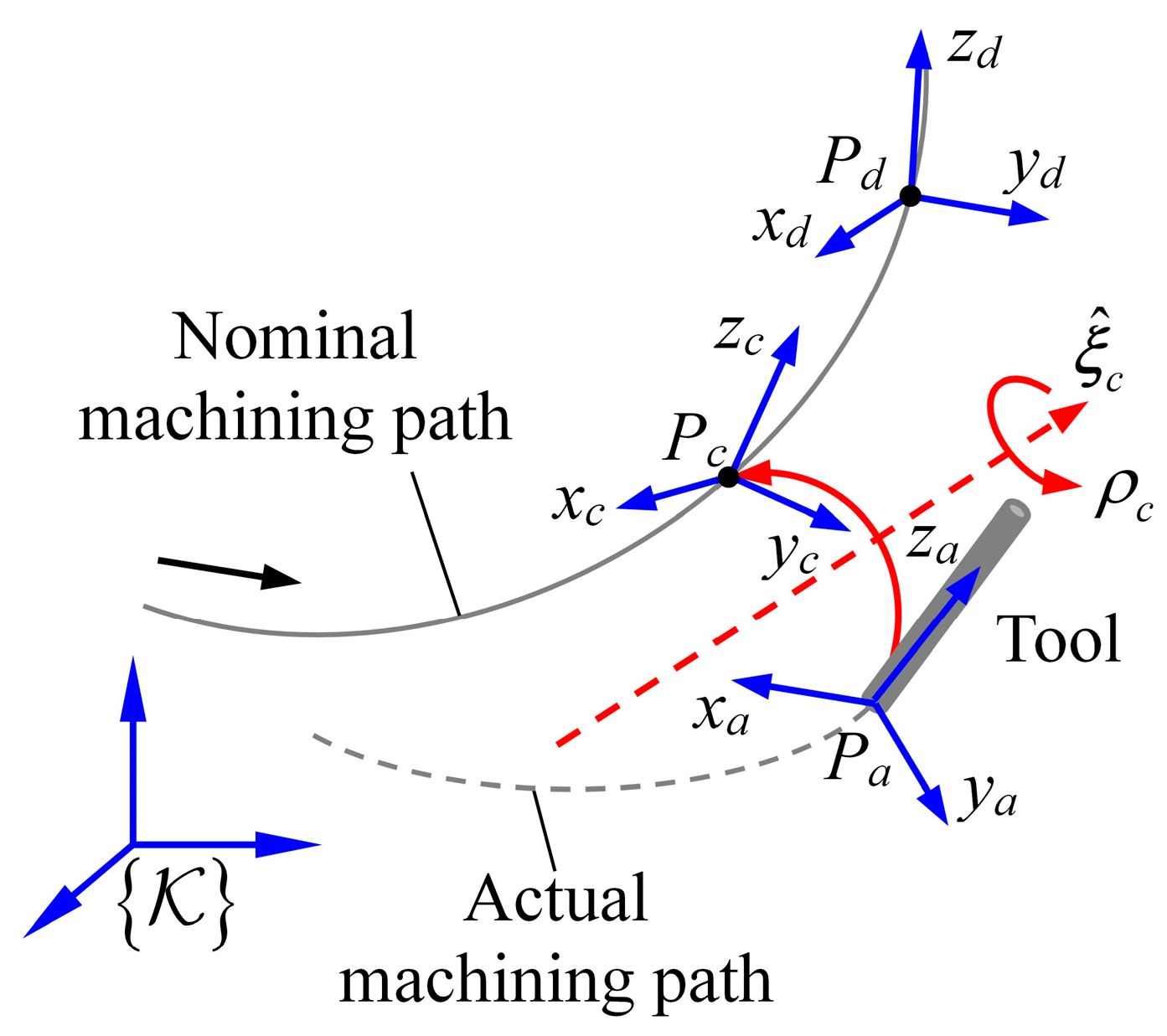
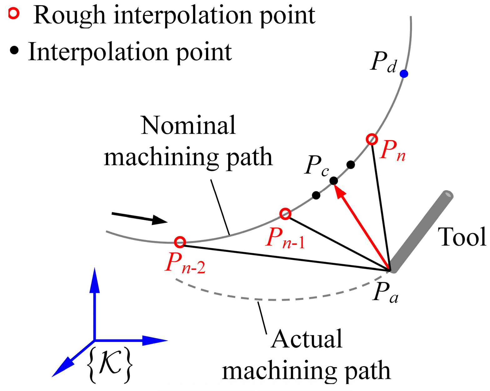
2.1. Definition of Contour Error

The end-effector motion of the TriMule hybrid robot can be kinematically described through the output motion of its R(RP)RRR kinematic chain. Building upon the fundamental principles of rigid-body screw theory [31,32], this study employs six-dimensional exponential coordinates to formulate a comprehensive contour error model for the hybrid robot. This method draws on fundamental concepts from the screw theory in robotic mechanisms. During the error modeling process, both positional and orientation errors are represented within a column vector, resulting in a more concise expression.
To enable the rigorous development of the contour error model for the hybrid robot, the following coordinate frames are systematically established. For a given machining trajectory, P d denotes the nominal tool tip position coordinate at time t , with P d representing its corresponding spatial point. Dynamic disturbances induce deviations between the actual and nominal tool postures. Accordingly, we define P a as the actual tool tip position coordinate and P c as the foot point position coordinate on the desired trajectory corresponding to P a , with P a and P c representing their corresponding spatial points, respectively. Coordinate frames P d , P a , and P c are established with their origins at points P d , P a , and P c , respectively. In each frame, the z-axis is aligned with the tool axis vector at the corresponding point ( P d , P a , or P c ), the x-axis is parallel to the rotation axis of the second joint in the wrist, and the y-axis follows the right-hand rule. Additionally, we define tracking frames K P d and K P c with axes parallel to the reference frame K and origins coincident with P d and P c , respectively. The contour error is then quantified as the SE(3) transformation between P a and P c , as shown in Figure 2, with the error twist ξ c expressed as follows.
ξ c = ρ c ξ ^ c
where
ρ c = arccos 1 2 tr R e 1 ,   ξ ^ c = v c ω c ,   T e = X a 1 X c = R e P e 0 1 ,   v c = G 1 ρ c P e
ω c × = 1 2 sin ρ c R e R e T ,   G 1 ρ c = 1 ρ c 1 1 2 ω c × + 1 ρ c 1 2 cot ρ c 2 ω c × 2
Here, ξ ^ c denotes the unit screw axis relative to P c ; ρ c denotes the magnitude of the contour error; X a and X c denote the homogenous transformation matrices of P a and P c with respect to K ; T e denotes the homogeneous transformation matrix of frame P a with respect to frame P c ; R e represents the corresponding rotation matrix, and p e = P c P a ; t r R e denotes the trace of matrix R e ; ω c × denotes the anti-symmetric matrix of ω c , and performs an isomorphism transformation on it to obtain ω c . In this paper, the above process is represented as ξ c × = log X a 1 X c , and subsequently, an isomorphism transformation of ξ c × yields ξ c . The modeling procedure draws upon the matrix logarithm of rigid-body motions in general rigid-body kinematics. For detailed derivations, please refer to Reference [31].

2.2. Modeling of Contour Error

In the contour error twist formulation of Equation (1), X a is computed through forward kinematics using grating sensor measurements, while X c is derived from the foot point coordinates. A precise foot point coordinate prediction is therefore critical for an accurate contour error estimation. Although iterative point-seeking methods provide advantages including high precision and the elimination of complex geometric computations [33], their computational efficiency is limited by sequential point-wise comparisons. To address this limitation, this paper introduces a hierarchical local search strategy that enhances the computational efficiency of iterative point-seeking methods. The proposed approach incorporates an interpolation technique adapted from numerical control (NC) systems, implementing a dual-phase interpolation process consisting of (a) coarse-to-fine segmentation to localize the foot point position and (b) precise coordinate determination through trajectory segment reconstruction algorithms.
In NC systems, motion commands generated by the rough interpolator are accessible to users, while fine-interpolated trajectories remain unavailable as fine interpolation occurs within the position feedback control loop. This necessitates trajectory reconstruction from rough interpolation segments. The nth rough interpolation segment n 1 t Δ , n t Δ of a continuous path should be considered, where t Δ represents the rough interpolation period. P n 1 and P n denote the segment’s start and end points, with corresponding homogeneous transformation matrices X n 1 and X n relative to frame K . Following the methodology in Reference [33], we reconstruct the tool configuration matrix with respect to K at any time n 1 t Δ + δ t   0 δ t t Δ through interpolation, thereby enabling complete trajectory reconstruction for arbitrary rough interpolation segments.
To account for response delays caused by hysteresis effects in both mechanical and servo control systems, this study implements a backward search strategy for foot point coordinate P c determination. This unidirectional search methodology effectively resolves the multi-solution problem inherent in foot point identification. Building upon the interpolation reconstruction framework, we propose a hierarchical local search algorithm specifically designed for machining trajectories exhibiting gradual curvature variations:
(1) The rough interpolation period t Δ is initialized, and the current rough interpolation segment is cached along with k subsequent segments in a dedicated register.
(2) The algorithm initiates from the terminal point of the relevant rough interpolation segment and performs a reverse sequential comparison of Euclidean distances between point P a and each rough interpolation point. For consecutive interpolation points P n 2 , P n 1 , and P n , when both conditions P a P n 2 P a P n 1 and P a P n P a P n 1 are met, the foot point P c is localized within the interval P n 2 , P n , as illustrated in Figure 3.
(3) Using the interpolation reconstruction method, fine interpolation is executed within the intervals P n 1 , P n and P n 2 , P n 1 . The interpolation density per rough interpolation period is set to n int steps with a time increment of t int = t Δ / n int + 1 . The homogeneous transformation matrices X n 1 , k n 1 and X n , k n with respect to K at interpolated points k n 1 ( 0 < k n 1 n int , with its corresponding time of n 2 t Δ + k n 1 t int ) and k n ( 0 < k n n int , and with its corresponding time of n 1 t Δ + k n t int ) within the (n − 1)th and nth rough interpolation segments, are computed. The nominal position coordinates P n 1 , k n 1 and P n , k n of the tool tip point and the orientation matrices R n 1 , k n 1 and R n , k n of the tool are obtained.
(4) A bisection method is applied to the two interpolation segments to precisely locate foot point P c , satisfying the following geometric constraint:
P a P c = min min t [ n 2 t Δ , n 1 t Δ ] P a P n 1 , k n 1 , min t [ n 1 t Δ , n t Δ ] P a P n , k n
Accordingly, the foot point coordinate P c corresponding to the tool tip point P a and the nominal direction vector of the tool axis at the foot point are obtained.
After the geometric calibration of the hybrid robot, transmission errors (such as those from reducers and ball screw-nut mechanisms) and elastic deformations in both the transmission system and linkages become the primary error sources affecting end-effector dynamic accuracy. Since the end-effector motion can be kinematically equivalent to that of an R(RP)RRR kinematic chain’s terminal, the influence of error sources from other branches on the end-effector accuracy can be similarly and equivalently mapped to the effects of error sources in this R(RP)RRR kinematic chain. Grating sensors installed on the parallel mechanism’s passive limb and wrist enable the real-time measurement of the R(RP)RRR kinematic chain’s motion deviations. δ ρ a , j , 4 represents the joint-angle/displacement error (measured vs. nominal) for the jth joint in Chain 4 ( j = 1 6 ), as shown in Figure 4. At this stage, the desired position of the tool tip point coincides with point P d , while the actual position aligns with point P a . Based on the superposition principle of serial kinematic chains, the tool’s error twist relative to point P d is obtained.
ξ e , C = j = 1 6 δ ρ a , j , 4 ξ ^ t a , j , 4
where ξ ^ t a , j , 4 denotes the unit permitted twist of the jth joint axis ( j = 1 6 ) in Chain 4 with respect to point P d .
Based on the aforementioned definition of contour error, the contour error represents the pose deviation of the robot’s tool at the actual point P a relative to its pose at the foot point P c . The error twist shown in Equation (3) describes the pose deviation of the tool at P a relative to the nominal position P d . Therefore, by utilizing the transformation relationships between coordinate frames, the contour error twist relative to point P c can be derived from Equation (3).
ξ c = Ad g d c ξ e , C
where
T d = R d p d 0 1 ,   T c = R c p c 0 1 ,   R c d = R c T R d ,   p c d = p d p c ,   Ad g d c = R c d R c d p c d × 0 R c d
Here, T d and T c denote the homogeneous transformation matrix of frames P d and P c with respect to K , respectively; p c d × denotes the anti-symmetric matrix of p c d ; Ad g d c denotes the adjoint transformation matrix of P d with respect to P c .

3. Control Strategy of Contour Error
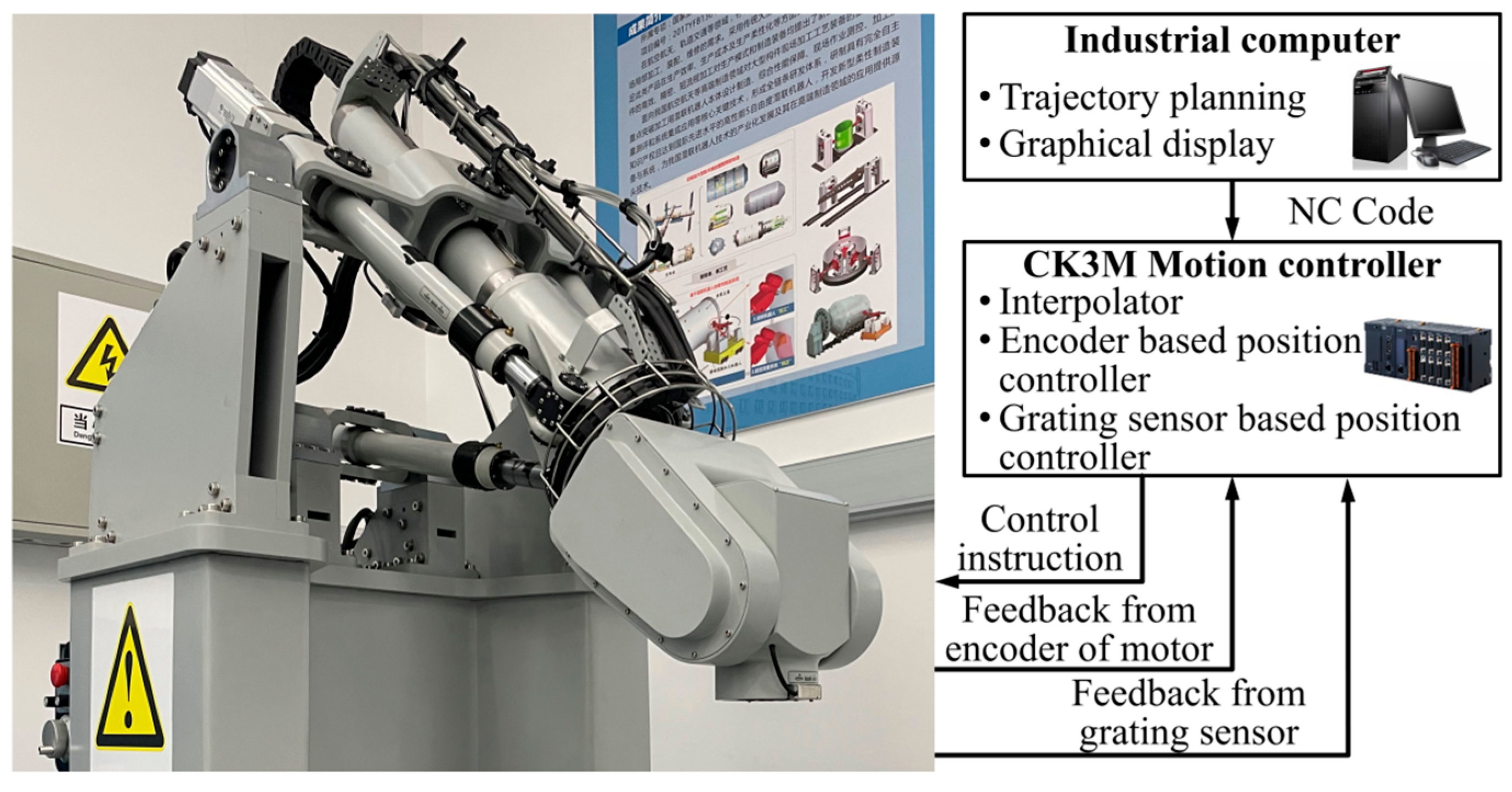
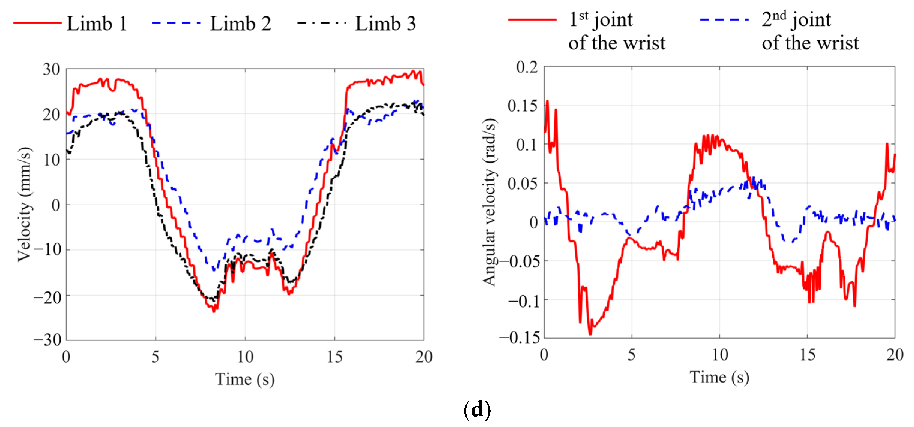
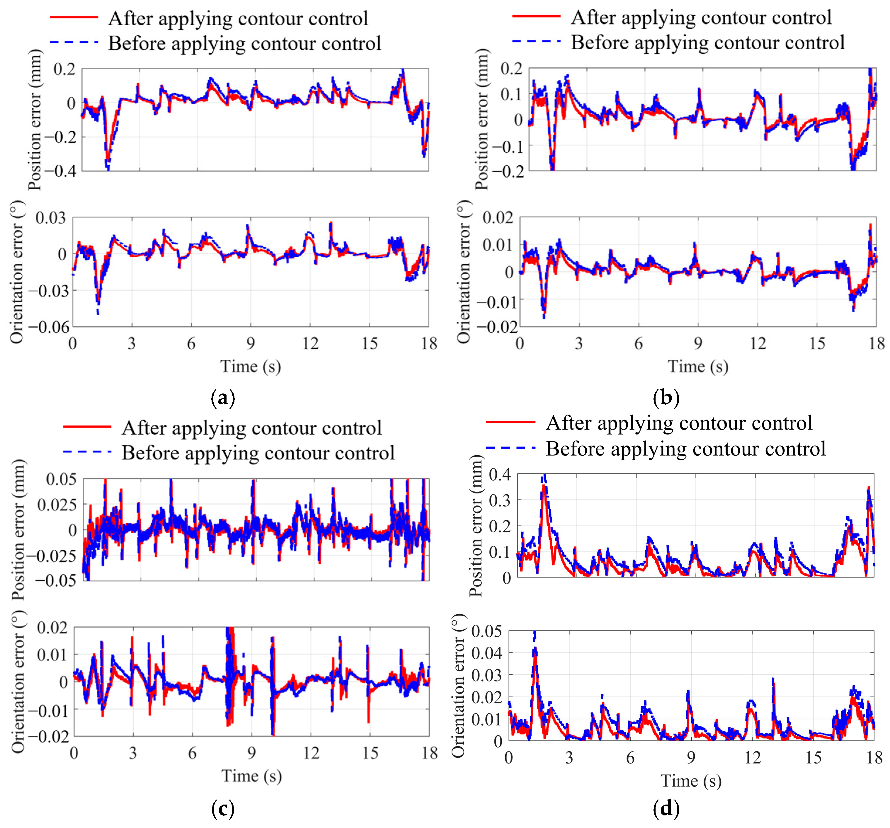
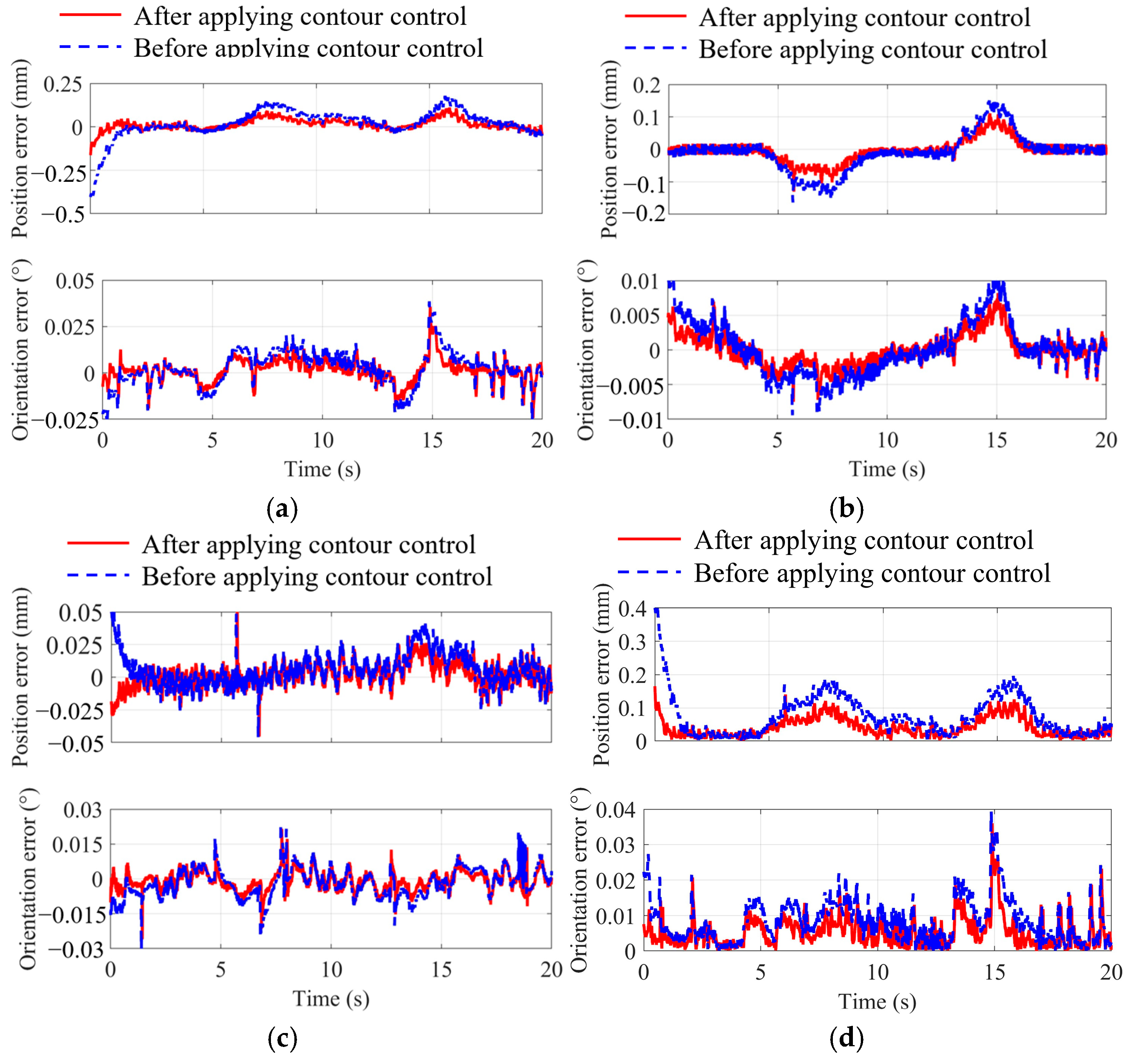
The implementation of the proposed contour error control strategy fundamentally relies on grating sensor-based position feedback control. We developed an innovative dual-position feedback control architecture that integrates grating sensor measurements with motor encoder data, comprising a grating sensor-based position controller and a motor encoder-based position controller in a cascaded configuration [34]. Following cascade control principles, the position controller output provides the reference input for the speed controller, while the grating sensor feedback signal undergoes two essential transformations—the inverse kinematic conversion of the hybrid robotic system and the subsequent integration—before being utilized in the motor encoder-based control loop. This dual-feedback architecture proves particularly effective for system error compensation since grating sensor measurements inherently capture cumulative errors from both driven joints and the complete transmission chain. The implemented control scheme effectively addresses tracking errors originating from transmission system inaccuracies and elastic deformations in critical components including reducers and screw-nut assemblies. As shown in Figure 5, the derived contour error control strategy builds upon this dual-position feedback framework, where the forward kinematics model computes tool position/orientation using Limb 4 joint parameters, while the inverse velocity model determines driven joint velocities in both the parallel mechanism and wrist based on the tool’s velocity twist.
Building upon the PI (P—proportional; I—integral) plus feedforward control architecture, we develop a grating sensor-based position feedback control law, and it is expressed in the form of six-dimensional exponential coordinates as follows:
ξ t , C t = Ad X a 1 X d ξ t , C t + k p p , C ξ e , C t + k p i , C ξ e , C t dt
where k p p , C = diag k p p , C , 1 k p p , C , 6 , and k p i 1 , C = diag k p i , C , 1 k p i , C , 6 . Here, to facilitate the formulation of the control law using the robot tool’s error twist, this paper defines points C and C as the reference points for the nominal and actual configurations of the robot, respectively. A follow-up reference frame K C is established with axes parallel to K and the origin instantaneously coincident with C ; ξ t , C t denotes the tool’s velocity twist relative to C after grating sensor-based position feedback adjustment; ξ t , C t represents the nominal tool velocity twist relative to C; k p p , C , j and k p i , C , j ( j = 1 6 ) are the proportional and integral gains, respectively; Ad X a 1 X d represents the adjoint transformation matrix of X a 1 X d , mapping the feedforward velocity twist ξ t , C t to frame K C , and X d and X a correspond to the nominal and actual tool configurations relative to K ; and the nominal velocity twist ξ t , C t is derived from ξ t , C × = X ˙ d X d 1 .
The contour error control objective ensures precise alignment between the tool’s actual posture and its nominal posture at the foot point, effectively implementing a set-point control following the dual-position feedback scheme. This paper takes the position contour error control as an example to elucidate the design process of a contour controller. After the aforementioned adjustment based on the grating sensor-based position controller, the actual position of the tool’s tip point of the hybrid robot is denoted as C , and the coordinates of the actual position at any given moment are defined as p a , C . The corresponding coordinates of the foot point on the nominal machining trajectory are p c , C . Based on this, the established error equation and error dynamic equation are as follows:
δ c t = p a , C t p c , C t ,   δ ˙ c t = p ˙ a , C t p ˙ c , C t
A position contour error controller is designed using the Lyapunov stability theory, and the Lyapunov function is defined as follows:
V δ = 1 2 δ c T t δ c t
When δ ˙ c t 0 , the condition V δ > 0 is always satisfied. Differentiating the above equation with respect to time yields the following equation:
V ˙ δ = δ c T t δ ˙ c t
When δ ˙ c t 0 , there exist various forms of error dynamic equations that ensure V ˙ δ < 0 . Here, a simple exponential convergence approach is designed, which is expressed as follows:
δ ˙ c t = k p , c δ c t
Where k p , c = diag k p , c , x k p , c , y k p , c , z , and k p , c , x , k p , c , y and k p , c , z all represent proportional gains.
Substituting Equation (9) into Equation (6) yields the following position contour control law:
ξ p t = p ˙ a , C t + k p , c p a , C t p c , C t
Following the above control law design procedure and expressing it in the form of six-dimensional exponential coordinates, a contour control law incorporating proportional control is derived.
ξ c , C t = ξ t , C t + k c , C Ad X a 1 X c ξ c t
where k c , C = diag k c , C , 1 k c , C , 6 ; ξ c , C t represents the adjusted tool velocity twist relative to C after both position feedback and contour error control; k c , C , j ( j = 1 6 ) denotes the proportional gain; Ad X a 1 X c denotes the adjoint transformation matrix of X a 1 X c , expressing the contour error twist ξ c in K C ; and X c represents the nominal tool posture at the foot point relative to K .
The result corresponding to Equation (11) serves as the input for the ‘inverse velocity’ in Figure 5. In the dual-position feedback controller illustrated in Figure 5 (i.e., the grating sensor-based position controller + the motor encoder-based position controller), the grating sensor-based position controller is used to regulate the tracking error of the tool, while the motor encoder-based position controller adjusts the tracking error of the motor rotor. It should be noted that the motor encoder-based position controller is consistent with a traditional semi-closed-loop feedback controller, and proportional control is employed in this scheme.

4. Verification

Experimental verification was conducted using the TriMule-200 hybrid robot (the axial stiffness at the robot end-effector reference point is 0.8 N/μm, while the lateral stiffness is 1.7 N/μm), as illustrated in Figure 6. The robotic system incorporates a distributed control architecture featuring a high-performance motion controller (CK3M-CPU121, OMRON Corporation; specifications: 1 GB RAM, 1 GB built-in flash memory, and dual-core 1 GHz CPU) interconnected with servo drivers through a real-time EtherCAT communication network. The servo drivers are configured to operate in the velocity control mode. The motion control system integrates a dual-loop feedback architecture comprising the following: (1) a primary position feedback controller based on motor encoder measurements, implemented through CK3M’s built-in integration module, and (2) a secondary position feedback loop utilizing grating sensor data, along with a contour error controller, both developed using CK3M’s custom algorithm development platform. This hierarchical control structure leverages the high-resolution grating sensor feedback to augment the conventional encoder-based position control, while the dedicated contour error controller enhances trajectory tracking performance. The implementation fully utilizes the CK3M motion controller’s native functionality for basic control loops and its programmable algorithm features for advanced compensation strategies. The circular and linear grating sensors utilize RESM20USA075 (with an accuracy of ±0.38″) and RTLC20-S (with an accuracy of ±5 μm/m) from Renishaw Corporation, respectively. The geometrical dimensions of the hybrid robot are shown in Table 1. The parameters of the motor encoder-based position controller were tuned using the Ziegler–Nichols (Z-N) method. In contrast, the tuning process for both the grating sensor-based position controller and the contour controller was more complex; therefore, a trial-and-error approach was adopted in this study. The finalized control parameters obtained through tuning are listed in Table 2.
The TriMule-200 hybrid robot has been primarily engineered for metal-cutting applications, with its design optimized to address the specific demands of this field. A key feature of the robot is the addition of a third rotational degree of freedom in its wrist, which significantly enhances the robot’s overall flexibility and maneuverability. This added degree of freedom is particularly crucial as it aids in avoiding singular configurations that might otherwise compromise the precision and efficiency of the robot’s movements. In this context, the position and orientation of the end-effector are determined by selecting two critical reference points: the central point of the output side and the axis of the third reducer of the wrist. This approach ensures that the robot can maintain accurate and smooth movements throughout its operational range. To validate the effectiveness of the proposed contour control strategy, a butterfly-shaped trajectory (with significant curvature variations) and a spatial S-shaped trajectory were selected as test trajectories. The butterfly-shaped trajectory, characterized by high curvature fluctuations, was employed to verify the universality of the contour error modeling and control method. The S-shaped trajectory, a standard test path for five-axis milling equipment, effectively reflects the dynamic accuracy of the robot end-effector. These geometric paths, along with their corresponding feed rate profiles, are depicted in Figure 7. During the experimental setup, the CK3M programmable multi-axis controller was utilized, with rough and fine interpolation periods set to 4 ms and 1 ms, respectively. The contour error of the hybrid robot was calculated using the data obtained from the grating sensors, in accordance with the established contour error model.
A comparative analysis of contour errors before and after applying the contour control is presented in Figure 8 and Figure 9. The results illustrate the following: (1) the position (orientation) contour error components along (around) each axis of the reference frame (Figure 8a–c or Figure 9a–c) and (2) the total magnitude of both position and orientation contour errors (Figure 8d or Figure 9d). The maximum (MAX) and root mean square (RMS) values of the errors are tabulated in Table 3. Notably, the experimental contour errors were derived from grating sensor measurements using the established contour error model.
According to Table 3 and Figure 8 and Figure 9, for the butterfly-shaped trajectory, compared to before applying the contour control, the maximum and root mean square (RMS) values of the position (orientation) contour error decreased by 15.42% (17.06%) and 23.42% (24.51%), respectively, after applying the contour control, thereby improving the contour accuracy for such trajectories with large curvature. By comparing the variation pattern of the contour error curve in Figure 8 with the trajectory velocity and acceleration curves in Figure 7c, it can be observed that high acceleration and high jerk significantly influence the contour error. For the S-curve trajectory, after applying the contour control, the maximum and RMS values of the position (orientation) contour error decreased by 59.42% (8.84%) and 49.95% (34.62%), respectively, enhancing the contour accuracy for such spatially shaped trajectories. For both types of trajectories, overall, the implementation of contour control reduced the magnitude of the contour error and its components along (around) each coordinate axis. The introduction of multi-loop control affects the response speed of the control system. Due to response hysteresis, particularly for the contour error components along (around) each coordinate axis, larger contour errors still occur in regions with high velocity and acceleration. Owing to the relatively low weight (~100 kg) of the TriMule 200 hybrid robot and the high stiffness of its parallel mechanism, the dynamic accuracy of the end-effector during an unloaded operation is significantly affected by joint friction. During experimental validation, the designed contour controller could not account for frictional effects due to both the limited sampling frequency of the grating sensors and filters implemented in the motion controller, thereby compromising its control performance. Furthermore, both the contour control and the grating sensor-based position feedback control for this class of hybrid robots constitute multi-input multi-output (MIMO) systems, rendering controller parameter tuning particularly challenging. In this study, the trial-and-error method was employed to tune the parameters of both the contour controller and the position feedback controller. Consequently, the controller parameters may not be at their optimal values, which could further influence the control performance. From the perspective of the entire machining path, the overall contour accuracy improved to some extent after applying contour control, validating the effectiveness of the proposed contour control strategy. Future work will focus on integrating friction compensation techniques, advanced controller parameter tuning methods, and more sophisticated control strategies (e.g., sliding mode control, robust control, and model predictive control) to enhance the contour accuracy of hybrid parallel robots.

5. Conclusions

This paper presents a contour error modeling method and a contour control strategy for the TriMule hybrid robot using measured information from grating sensors. (1) Given the characteristics of pose coupling in the hybrid robot, we propose a contour error modeling method that employs six-dimensional exponential coordinates to effectively describe the contour error. Meanwhile, an improved iterative point-seeking method is presented, incorporating both rough and fine interpolation within the numerical control system to accurately calculate the foot point coordinate. The proposed contour error modeling method is applicable to robots with any number of degrees of freedom. (2) To mitigate the impact of joint elasticity and transmission error on contour accuracy and to reduce the contour error by improving the multi-axis motion performance, a contour error controller is developed based on a grating sensor and motor encoder-based dual-position feedback control architecture. Experiment verification was carried out on the TriMule-200 hybrid robot, and the effectiveness of the proposed contour control strategy was validated by comparing the experimental results before and after applying the contour control method.

Author Contributions

Methodology, X.S.; Software, T.Z.; Data curation, Y.D.; Writing—review & editing, H.L. and J.X. All authors have read and agreed to the published version of the manuscript.

Funding

This research was funded by the National Natural Science Foundation of China under grants 52475028 and 52325501.

Data Availability Statement

Data will be made available from the corresponding author on reasonable request.

Conflicts of Interest

The authors declare no conflicts of interest.

References

  1. Yue, W.; Liu, H.T.; Huang, T. An approach for predicting stiffness of a 5-dof hybrid robot for friction stir welding. Mech. Mach. Theory 2022, 175, 104941. [Google Scholar] [CrossRef]
  2. Dong, C.L.; Liu, H.T.; Huang, T.; Chetwynd, D.G. A screw theory-based semi-analytical approach for elastodynamics of the tricept robot. J. Mech. Robot. 2019, 11, 031005. [Google Scholar] [CrossRef]
  3. Aydin, M. Real-time sliding mode and moving sliding mode control of 3-dof linear parallel robot. Machines 2025, 13, 190. [Google Scholar] [CrossRef]
  4. Guechi, E.; Bouzoualegh, S.; Zennir, Y.; Blazic, S. MPC control and LQ optimal control of a two-link robot arm: A comparative study. Machines 2018, 6, 37. [Google Scholar] [CrossRef]
  5. Xiao, Q.B.; Wan, M.; Yang, Y.; Zhang, W.H. Pre-compensation of contour errors for five-axis machine tools through constructing a model reference adaptive control. Mech. Mach. Theory 2023, 187, 105258. [Google Scholar] [CrossRef]
  6. Wang, Z.; Hu, C.X.; Zhu, Y.; Zhu, L.M. Prediction-model-based contouring error iterative precompensation scheme for precision multiaxis motion systems. IEEE-ASME Trans. Mechatron. 2021, 26, 2274–2284. [Google Scholar] [CrossRef]
  7. Zhao, H.; Li, X.F.; Ge, K.D.; Ding, H. A contour error definition, estimation approach and control structure for six-dimensional robotic machining tasks. Robot. Comput.-Int. Manuf. 2022, 73, 102235. [Google Scholar] [CrossRef]
  8. Jia, Z.Y.; Ma, J.W.; Song, D.N.; Wang, F.J.; Liu, W. A review of contouring-error reduction method in multi-axis CNC machining. Int. J. Mach. Tools Manuf. 2018, 125, 34–54. [Google Scholar] [CrossRef]
  9. Liu, Y.; Wan, M.; Xiao, Q.B.; Qin, X.B. Combined predictive and feedback contour error control with dynamic contour error estimation for industrial five-axis machine tools. IEEE Trans. Ind. Electron. 2022, 69, 6668–6677. [Google Scholar] [CrossRef]
  10. Li, J.A.; Yue, R.J.; Fei, Y.M. Five-axis contour error control based on numerical control data. Machines 2023, 11, 85. [Google Scholar] [CrossRef]
  11. Kim, S.H.; Min, B.K. Real-time tool path modification for machine tool contour error reduction. Int. J. Adv. Manuf. Technol. 2020, 120, 6969–6981. [Google Scholar] [CrossRef]
  12. Song, D.N.; Zhong, Y.G.; Ma, J.W. Third-order contour-error estimation for arbitrary free-form paths in contour-following tasks. Precis. Eng. 2019, 60, 85–92. [Google Scholar] [CrossRef]
  13. Wang, Z.; Hu, C.X.; Zhu, Y. Double taylor expansion-based real-time contouring error estimation for multiaxis motion systems. IEEE Trans. Ind. Electron. 2019, 66, 9490–9499. [Google Scholar] [CrossRef]
  14. Yang, J.X.; Altintas, Y. A generalized on-line estimation and control of five-axis contouring errors of CNC machine tools. Int. J. Mach. Tools Manuf. 2015, 88, 9–23. [Google Scholar] [CrossRef]
  15. Li, X.F.; Zhao, H.; Zhao, X.; Ding, H. Interpolation-based contour error estimation and component-based contouring control for five-axis CNC machine tools. Sci. China Technol. Sci. 2018, 61, 1666–1678. [Google Scholar] [CrossRef]
  16. Yang, M.; Yang, J.X.; Ding, H. A high accuracy on-line estimation algorithm of five-axis contouring errors based on three-point arc approximation. Int. J. Mach. Tools Manuf. 2018, 130, 73–84. [Google Scholar] [CrossRef]
  17. Sencer, B.; Altintas, Y.; Croft, E. Modeling and control of contouring errors for five-axis machine tools-Part I: Modeling. J. Manuf. Sci. Eng. Trans. ASME 2009, 131, 031006. [Google Scholar] [CrossRef]
  18. Hu, C.X.; Yu, J.C.; Wang, Z.; Zhu, Y. An iterative contouring error compensation scheme for five-axis precision motion systems. Mech. Syst. Signal Process. 2022, 178, 109226. [Google Scholar] [CrossRef]
  19. Koren, Y. Cross-coupled biaxial computer control for manufacturing systems. J. Dyn. Sys. Meas. Control. ASME 1980, 102, 265–271. [Google Scholar] [CrossRef]
  20. Huo, F.; Poo, A.N. Improving contouring accuracy by using generalized cross-coupled control. Int. J. Mach. Tools Manuf. 2012, 63, 49–57. [Google Scholar] [CrossRef]
  21. Ouyang, P.R.; Dam, T.; Pano, V. Cross-coupled PID control in position domain for contour tracking. Robotica 2015, 33, 1351–1374. [Google Scholar] [CrossRef]
  22. Kang, Z.; Lin, W.Y.; Liu, Z.T.; Xu, R.Q. Accurate Contour Error Estimation-based robust contour control for dual-linear-motor-driven gantry stages. Mechatronics 2024, 100, 103174. [Google Scholar] [CrossRef]
  23. Hu, C.X.; Lin, S.Z.; Wang, Z.; Zhu, Y. Task space contouring error estimation and precision iterative control of robotic manipulators. IEEE Robot. Autom. Lett. 2022, 7, 7826–7833. [Google Scholar] [CrossRef]
  24. Chen, S.L.; Hsieh, S.M. Iterative learning contouring control: Theory and application to biaxial systems. Mechatronics 2023, 89, 102932. [Google Scholar] [CrossRef]
  25. Dai, J.; Wan, M.; Qin, X.B.; Zhang, W.H. A time-delay-based sliding mode controlling method for reducing contour errors of machine tools. J. Manuf. Process 2023, 106, 407–421. [Google Scholar] [CrossRef]
  26. Liu, Y.B.; Sun, W.C.; Buccella, C.; Cecati, C. Robust control of dual-linear-motor-driven gantry stage for coordinated contouring tasks based on feed velocity. IEEE Trans. Ind. Electron. 2023, 70, 6229–6238. [Google Scholar] [CrossRef]
  27. Sencer, B.; Altintas, Y. Modeling and control of contouring errors for five-axis machine tools-Part II: Precision contour controller design. J. Manuf. Sci. Eng. Trans. ASME 2009, 131, 031007. [Google Scholar] [CrossRef]
  28. Kornmaneesang, W.; Chen, S.L. MPC-based robust contouring control for a robotic machining system. Asian J. Control 2021, 23, 1212–1224. [Google Scholar] [CrossRef]
  29. Chen, S.L.; Hsieh, S.M.; Ta, T.Q. Iterative learning contouring control for five-axis machine tools and industrial robots. Mechatronics 2023, 94, 103030. [Google Scholar] [CrossRef]
  30. Kim, S.H. Feedforward compensation of contour errors in robotic machining system using compliance model. J. Manuf. Process 2023, 89, 142–149. [Google Scholar] [CrossRef]
  31. Kevin, M.L.; Frank, C.P. Modern Robotics-Mechanics, Planning, and Control; Cambridge University Press: Cambridge, UK, 2017; pp. 59–109. [Google Scholar]
  32. Featherstone, R. Rigid Body Dynamics Algorithms; Springer: Berlin/Heidelberg, Germany, 2008; pp. 7–87. [Google Scholar]
  33. Erkorkmaz, K.; Altintas, Y. High speed contouring control algorithm for CNC machine tools. In Proceedings of the ASME, IMECE98, Anaheim, CA, USA, 15–20 November 1998; pp. 463–469. [Google Scholar]
  34. Liu, H.T.; Yuan, H.; Shan, X.L.; Han, J.L.; Xiao, J.L. A grating sensor feedback-based dynamic accuracy control strategy of hybrid Robot. Aeronaut. Manuf. Technol. 2023, 66, 40–45. [Google Scholar]
Figure 1. TriMule hybrid robot: (a) CAD model and (b) schematic diagram.
Machines 13 00502 g001
Figure 2. Contour error of hybrid robot.
Machines 13 00502 g002
Figure 3. Prediction for foot point coordinate.
Machines 13 00502 g003
Figure 4. Error sources in kinetic chain R(RP)RRR.
Machines 13 00502 g004
Figure 5. Contour error control strategy.
Machines 13 00502 g005
Figure 6. TriMule-200 hybrid robot.
Machines 13 00502 g006
Figure 7. Verification trajectory. (a) Butterfly-shaped trajectory. (b) Spatial S-shaped trajectory. (c) Feed rate profile of driven joint along butterfly-shaped trajectory. (d) Feed rate profile of driven joint along S-shaped trajectory.
Machines 13 00502 g007aMachines 13 00502 g007b
Figure 8. Contour error of butterfly-curve trajectory. (a) Along (around) x-axis. (b) Along (around) y-axis. (c) Along (around) z-axis. (d) Amplitude.
Machines 13 00502 g008
Figure 9. Contour error of spatial S-curve trajectory. (a) Along (around) x-axis. (b) Along (around) y-axis. (c) Along (around) z-axis. (d) Amplitude.
Machines 13 00502 g009
Table 1. Geometrical dimensions of hybrid (mm).
abxbyedwdv
75167294.1283.593.8130
Table 2. Tuned parameters of regulators.
j = 1j = 2j = 3j = 4j = 5j = 6
k p p , C , i 1 × 10−21.5 × 10−21.5 × 10−23 × 10−32 × 10−31 × 10−3
k p i , C , i 1 × 10−31.2 × 10−31.2 × 10−31 × 10−31.1 × 10−30.6 × 10−3
k c , C , i 2 × 10−22 × 10−22 × 10−21 × 10−31 × 10−31 × 10−3
Table 3. Maximum and root mean square (RMS) values of errors.
After Applying Contour ControlBefore Applying Contour Control
Position Contour ErrorOrientation Contour ErrorPosition Contour ErrorOrientation Contour Error
Butterfly-Shaped Trajectory
MAX0.359 mm0.042°0.425 mm0.051°
RMS0.081 mm0.008°0.106 mm0.01°
Spatial S-shaped trajectory
MAX0.166 mm0.036°0.408 mm0.04°
RMS0.05 mm0.007°0.099 mm0.01°
Disclaimer/Publisher’s Note: The statements, opinions and data contained in all publications are solely those of the individual author(s) and contributor(s) and not of MDPI and/or the editor(s). MDPI and/or the editor(s) disclaim responsibility for any injury to people or property resulting from any ideas, methods, instructions or products referred to in the content.

